EP4400295A1 - Procédés de moulage pour la production de pneus - Google Patents
Procédés de moulage pour la production de pneus Download PDFInfo
- Publication number
- EP4400295A1 EP4400295A1 EP24150488.5A EP24150488A EP4400295A1 EP 4400295 A1 EP4400295 A1 EP 4400295A1 EP 24150488 A EP24150488 A EP 24150488A EP 4400295 A1 EP4400295 A1 EP 4400295A1
- Authority
- EP
- European Patent Office
- Prior art keywords
- mold
- tire
- sidewall
- tire mold
- plate
- Prior art date
- Legal status (The legal status is an assumption and is not a legal conclusion. Google has not performed a legal analysis and makes no representation as to the accuracy of the status listed.)
- Granted
Links
Images


Classifications
-
- B—PERFORMING OPERATIONS; TRANSPORTING
- B29—WORKING OF PLASTICS; WORKING OF SUBSTANCES IN A PLASTIC STATE IN GENERAL
- B29D—PRODUCING PARTICULAR ARTICLES FROM PLASTICS OR FROM SUBSTANCES IN A PLASTIC STATE
- B29D30/00—Producing pneumatic or solid tyres or parts thereof
- B29D30/06—Pneumatic tyres or parts thereof (e.g. produced by casting, moulding, compression moulding, injection moulding, centrifugal casting)
- B29D30/0601—Vulcanising tyres; Vulcanising presses for tyres
- B29D30/0606—Vulcanising moulds not integral with vulcanising presses
- B29D30/0629—Vulcanising moulds not integral with vulcanising presses with radially movable sectors
-
- B—PERFORMING OPERATIONS; TRANSPORTING
- B29—WORKING OF PLASTICS; WORKING OF SUBSTANCES IN A PLASTIC STATE IN GENERAL
- B29D—PRODUCING PARTICULAR ARTICLES FROM PLASTICS OR FROM SUBSTANCES IN A PLASTIC STATE
- B29D30/00—Producing pneumatic or solid tyres or parts thereof
- B29D30/06—Pneumatic tyres or parts thereof (e.g. produced by casting, moulding, compression moulding, injection moulding, centrifugal casting)
- B29D30/0601—Vulcanising tyres; Vulcanising presses for tyres
- B29D30/0606—Vulcanising moulds not integral with vulcanising presses
- B29D2030/0607—Constructional features of the moulds
- B29D2030/0617—Venting devices, e.g. vent plugs or inserts
-
- B—PERFORMING OPERATIONS; TRANSPORTING
- B29—WORKING OF PLASTICS; WORKING OF SUBSTANCES IN A PLASTIC STATE IN GENERAL
- B29D—PRODUCING PARTICULAR ARTICLES FROM PLASTICS OR FROM SUBSTANCES IN A PLASTIC STATE
- B29D30/00—Producing pneumatic or solid tyres or parts thereof
- B29D30/06—Pneumatic tyres or parts thereof (e.g. produced by casting, moulding, compression moulding, injection moulding, centrifugal casting)
- B29D30/0601—Vulcanising tyres; Vulcanising presses for tyres
- B29D30/0606—Vulcanising moulds not integral with vulcanising presses
- B29D30/0629—Vulcanising moulds not integral with vulcanising presses with radially movable sectors
- B29D2030/063—Vulcanising moulds not integral with vulcanising presses with radially movable sectors the moulds being split in upper and lower halves
Definitions
- the present invention generally relates to methods for curing/producing an annular rubber structure, in particular to a molding method for tires.
- the present invention more specifically relates to facilitate drawing a vacuum on the mold cavity to produce pneumatic and non-pneumatic tires having an advanced visual appearance.
- segmented tire mold is the segmented tire mold, as opposed to a two-piece tire mold.
- segmented tire molds include US 3,779,677 and US 3,867,504 .
- US 3,779,677 discloses a tire mold in which tread mold segments are moved radially by a coned ring between sidewall plates which bear against the moving segments.
- Link means connecting each segment to the upper plate enable the segments to be retracted into the ring by moving the upper plate.
- the link means provides sufficient relative separation between the upper plate and the segments to prevent friction, wear, and binding therebetween during such retraction.
- the tire mold includes a pair of sidewall mold plates, each of which carries a tire sidewall molding surface.
- a plurality of tread mold segments collectively cooperate with the sidewall molding surfaces to form a closed tire mold cavity.
- the tread mold segments are mounted respectively on a plurality of carrier segments which are movable inwardly and outwardly with respect to the tire mold axis and particularly radially thereof.
- Each of the carrier segments is provided with an inclined surface, as well as guiding surfaces (e.g., a T-slot).
- the respective inclined surfaces cooperate with conjugately inclined surfaces carried by the closing ring and define collectively cones convergent on the mold axis outwardly, i.e., upwardly, of the upper platen. Radial movement of the respective segments inwardly, toward the axis, is effected by axial movement of the ring toward the lower sidewall plate. As the upper platen and ring move downwardly, engagement of the bottom surface of the segment with the flange surface of the lower sidewall plate prevents further axial movement of the segment, thereby converting the relative motion between the ring and the segment to radially inward movement of the segment.
- each mold segment has to be provided with a large number of such venting devices or channels. This is, in particular, the case for winter tires because the tread blocks and their sipes require that all tiny elements of the tread be provided with a corresponding venting passage in the mold segments. It is expensive and time consuming to ensure venting in such a way. Venting devices may also be blocked which may result in quality problems and the need for intensive cleaning or maintenance.
- EP 2 881 230 A1 describes such a tire mold and process.
- This document describes a system for providing a vacuum in a segmented tire mold, the system comprising a vacuum container and a segmented tire mold. The vacuum container seals the tire mold to make it airtight.
- the tire mold has an upper sidewall assembly and a lower sidewall assembly, a plurality of radially moveable tread mold segments operable with the upper sidewall assembly and the lower sidewall assembly to define a tire mold cavity in the closed position of the tire mold, a conical actuating ring assembly surrounding the tread mold segments for providing a radial movement of the tread mold segments into engagement with the upper sidewall assembly and the lower sidewall assembly.
- the vacuum container comprises a top-sealing means between the actuating ring assembly and the upper sidewall assembly, and a bottom sealing means between the actuating ring assembly and the lower sidewall assembly, such that the tire mold is airtight and ready for evacuation or evacuated only when fully closed.
- the top sealing means and the bottom sealing means comprise silicone.
- the tire mold and the vacuum container have no sliding seals.
- US 4,573,894 and US 4,595,553 both describe a method and apparatus in which a tire mold is closed to within approximately one inch of full closure with a green tire in place therein for molding, and the tire mold is then evacuated employing a vacuum conduit before full mold closure whereby air within the mold cavity is evacuated and the necessity for vent holes in the tire mold is eliminated.
- the tire mold can be free of vent holes in the tread, sidewalls, and bead portions of the tire mold and includes, along the parting line, at least one vacuum conduit whereby the mold cavity may be evacuated to not more than 16932 Pa within not more than 60 seconds employing a source of vacuum.
- Seals are provided radially outward of the vacuum conduit along the parting line, and, where necessary, adjacent to any moveable bead ring associated with the tire mold. Seals are, preferably, of a type wherein a differential between pressures experienced by one seal surface and obverse seal surface causes a more effective sealing arrangement.
- US 7,056,109 describes a tire vulcanizing device that includes an upper plate and a lower plate which can be relatively displaced toward and away from each other, and a tire mold for vulcanizing and molding a tire arranged between the upper plate and the lower plate.
- the tire mold includes an upper and a lower side mold members arranged on the upper plate side and the lower plate side, respectively, and a plurality of sector mold members arranged between the upper and the lower side mold members.
- An outer ring for positioning the sector mold members in the radial direction is arranged on the lower plate side.
- An actuator means for opening the sector mold member is arranged on the lower plate, capable of vertical elevation.
- the invention relates to a method in accordance with claim 1 or 14 respectively.
- Dependent claims refer to preferred embodiments of the invention.
- a first preferred aspect of the invention relates to a molding process wherein a tire is molded within a tire mold.
- the tire mold has movable elements that can be moved to bring the tire mold into an open or into a closed position. In the closed position, the tire mold defines a tire mold axis.
- the tire mold includes a first and a second sidewall mold plates and a plurality of tread mold segments cooperating with the sidewall mold plates to form a tire mold cavity.
- the tread mold segments are movable radially inwardly and outwardly with respect to the tire mold axis.
- the process comprises:
- the first and second sidewall mold plates may be in abutment with the uncured tire.
- the mold cavity may be sealed in an airtight manner.
- the axial clearance between the at least one of the first and second sidewall mold plates may be created by moving the at least one of the first and second sidewall mold plates with a pneumatic or hydraulic actuator.
- the tread mold segments may be mounted slidingly to the first sidewall mold plate by respective retainer tees fixed to the tread mold segments and slidingly engaged in radial slots arranged on a first container plate carrying the first sidewall mold plate.
- the retainer tees and the slots may be dimensioned so as to allow for axial offset between the first sidewall plate and the tread mold segments.
- the radial clearance in the first intermediate position of the tire mold may amount to between 3 and 12 mm.
- the axial clearance in the second intermediate position of the tire mold may amount to between 3 and 12 mm.
- the radial clearance in the first intermediate position of the tire mold amounts to between 5 and 10 mm and the axial clearance in the second intermediate position of the tire mold amounts to between 5 and 10 mm.
- the tire mold may comprise first and second heating plates adjacent the first and second sidewall mold plates, respectively.
- the first and second heating plates may be a minimum distance apart from each other when the tire mold is in the closed position.
- the first and second heating plates may be spaced apart from each other further than the minimum distance when the tire mold is in the first and second intermediate positions.
- the axial clearance between the uncured tire and at least one of the first and second sidewall mold plates may be created by axially moving the first sidewall mold plate closer to or into abutment with the first heating plate.
- the axial clearance may be created between the uncured tire and the first sidewall mold plate by axially moving the first sidewall mold plate. Additionally, the creation of the axial clearance may release axial constraint on the uncured tire such that the uncured tire at least partially detaches from the second sidewall mold plate and air (or ambient fluid) is allowed to be drawn from an interstice between the uncured tire and the second sidewall plate.
- the molding process may comprise curing the tire when the mold is in the closed position.
- the invention relates to a method for closing a tire mold for curing rubber-based pneumatic or non-pneumatic tires, the tire mold comprising a first and a second sidewall mold plates and a plurality of tread mold segments cooperating with the sidewall mold plates to form a generally annular tire mold cavity, the tire mold cavity having a tire mold axis, and the tread mold segments being movable radially inwardly and outwardly with respect to the tire mold axis.
- the method may comprise:
- the mold cavity may be sealed in a gastight manner.
- the first and second sidewall mold plates may axially constrain the uncured tire.
- the axial clearance may be created between the uncured tire and the first sidewall mold plate by axially moving the first sidewall mold plate.
- the creation of the axial clearance may release axial constraint on the uncured tire such that the uncured tire may at least partially detach from the second sidewall mold plate and air may be allowed to be drawn from an interstice between the uncured tire and the second sidewall plate, by application of the vacuum.
- the axial clearance between the at least one of the first and second sidewall mold plates may be created by moving the at least one of the first and second sidewall mold plates with a pneumatic or hydraulic actuator.
- the tread mold segments may be mechanically coupled to an actuating ring so that the tread mold segments are constrained to move radially when the actuating ring is moved axially.
- the tire mold may be brought into the closed position by moving the actuating ring in an axial direction causing the tread mold segments to move radially inwardly.
- the tread mold segments may be mounted slidingly to the first sidewall mold plate by respective retainer tees fixed to the tread mold segments and slidingly engaged in radial slots arranged on a first container plate supporting the first sidewall mold plate.
- the retainer tees and the slots may be dimensioned so as to allow for an axial clearance between the first sidewall plate and the tread mold segments sufficient for the tire mold to be brought into the second intermediate position.
- the tire mold may comprise first and second heating plates adjacent the first and second sidewall mold plates, respectively.
- the first and second heating plates may be a minimum distance apart from each other when the tire mold is in the closed position.
- the first and second heating plates may be spaced apart from each other further than the minimum distance when the tire mold is in the first and second intermediate positions.
- the axial clearance between the uncured tire and at least one of the first and second sidewall mold plates may be created by axially moving the first sidewall mold plate closer to or into abutment with the first heating plate.
- the radial clearance in the first intermediate position of the tire mold may amount to 12 mm or less and the axial clearance in the second intermediate position of the tire mold may amount to 12 mm or less.
- azimuthal refers to a direction that is perpendicular to both the radial and axial directions in the location under consideration. Instead of “azimuthal,” the word “angular” may be used.
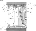
- FIG. 4 shows a partial cross-sectional view of a tire mold 10 in its closed position.
- the tire mold 10 comprises tread mold segments 12 that may be moved radially by a coned actuating ring 14.
- the movement of each tread mold segment 12 is constrained to a radial translation between a first container plate 16 and a second container plate 18, which bear (at least indirectly) against the moving tread mold segments 12.
- the first and second container plates 16, 18 carry first and second annular sidewall mold plates 20, 22, respectively, which extend around the axis of the mold 10 (not shown).
- the first and a second sidewall mold plates 20, 22 and the plurality of tread mold segments 12 cooperate to form a tire mold cavity 24.
- the actuating ring 14 may be pushed into the direction of the second container plate 18 by a first heating plate 26.
- the second container 18 is supported by a second heating plate 28.
- An intermediate ring 30 is fixed on the actuating ring 14 so as to be arranged between and the first container 26 and the actuating ring 14.
- the radially inward end of the intermediate ring 30 comprises a cylindrical flange 32, cooperating with an annular seal 34 on an opposed cylindrical face of the first container plate 16.
- FIG. 4 further schematically shows a green (uncured) tire 36 arranged in the mold cavity 24.
- FIGS. 1 to 4 A process according to a preferred embodiment of the invention is now described with reference to FIGS. 1 to 4 .
- An uncured tire 36 is arranged in the mold cavity 24 of the tire mold 10 when the tire mold 10 is in an open position (not shown).
- the tire mold 10 is then brought from the open position into a first intermediate, partially closed, position, illustrated in FIG. 1 .
- the tread mold segments 12 occupy a substantially final axial position but remain separated radially from the uncured tire 36 by a radial clearance 38 and from the first and second sidewall mold plates 20, 22 by respective cylindrical gaps 39A, 39B.
- the first container plate 16 carrying the first sidewall mold plate 20 is brought into a position parallel to the second container plate 18 carrying the second sidewall mold plate 22.
- the first and second sidewall mold plates 20, 22 thus confine the green tire 36 in axial direction.
- the first heating plate 26 is then put into place and used to push the actuating ring 14 axially into the direction of the second heating plate 28 and thereby move the tread mold segments 12 radially inwardly.
- the first heating plate 26 is not at its minimum distance from the second heating plate 28.
- the tread mold segments 12 are not at their respective radially innermost positions, i.e., the positions they take when the mold 10 is completely closed.
- the tire mold 10 is brought into a second intermediate position, illustrated in FIG. 2 .
- the first container plate 16 and the first sidewall mold plate 20 fixed to it are moved away from the second container plate 18 and the second sidewall mold plate 22, so that an axial clearance 40 is obtained between the uncured tire 36 and the first sidewall mold plate 20.
- the creation of the axial clearance 40 releases axial constraint on the uncured tire 36, which may result in the uncured tire 36 at least partially detaching from the second sidewall mold plate 22.
- the radially inner flange 32 of the intermediate ring 30 continues to cooperate with the seal 34 on the first container plate. The fluid-tight enclosure including the mold cavity 24 is thus preserved.
- the tread mold segments 12 are connected slidingly to the first container plate 16 by respective retainer tees 42 fixed on the tread mold segments 12.
- the first container plate 16 has radial slots, into which the retainer tees 42 are slidingly engaged.
- the retainer tees and the slots are dimensioned so as to allow for an axial offset between the first sidewall plate 20 and the tread mold segments 12 sufficient for the tire mold 10 to be brought into the second intermediate position.
- the length of the stems of the retainer tees 42 and the thickness of the first container plate 16 around the radial slots are selected in such a way that there is a clearance allowing axial movement of the first container plate 16 carrying the first sidewall mold plate 10 relative to the tread mold segments 12.
- the process presented herein may be effective for removal of air from the mold cavity. This may alleviate the need for vent holes in the sidewall plates. In certain configurations, the number of vent holes in the sidewall mold plates my thus be drastically reduced. In preferred configurations, vent holes may be completely eliminated from the sidewall mold plates. Accordingly, the processes disclosed herein are preferably carried out with sidewall mold plates comprising a low areal density of vent holes or no vent holes at all.
- the first container plate 16 and the first sidewall mold plate 20 fixed to it are moved back towards the second container plate 18 and the second sidewall mold plate 22, so that the uncured tire 36 becomes again firmly seized in axial direction ( FIG. 3 ).
- the mold 10 While maintaining the mold cavity under vacuum, the mold 10 is then brought into its closed position ( FIG. 4 ) by moving the first heating plate 26 closer to the second heating plate 28, thereby axially moving the actuating ring 14 and thus pushing the tread mold segments 12 radially inwardly.
- the tire may be cured.
Landscapes
- Engineering & Computer Science (AREA)
- Mechanical Engineering (AREA)
- Moulds For Moulding Plastics Or The Like (AREA)
- Heating, Cooling, Or Curing Plastics Or The Like In General (AREA)
Applications Claiming Priority (1)
| Application Number | Priority Date | Filing Date | Title |
|---|---|---|---|
| US18/152,810 US12290999B2 (en) | 2023-01-11 | 2023-01-11 | Molding method for tire production |
Publications (2)
| Publication Number | Publication Date |
|---|---|
| EP4400295A1 true EP4400295A1 (fr) | 2024-07-17 |
| EP4400295B1 EP4400295B1 (fr) | 2026-02-25 |
Family
ID=89474158
Family Applications (1)
| Application Number | Title | Priority Date | Filing Date |
|---|---|---|---|
| EP24150488.5A Active EP4400295B1 (fr) | 2023-01-11 | 2024-01-05 | Procédés de moulage pour la production de pneus |
Country Status (2)
| Country | Link |
|---|---|
| US (1) | US12290999B2 (fr) |
| EP (1) | EP4400295B1 (fr) |
Citations (9)
| Publication number | Priority date | Publication date | Assignee | Title |
|---|---|---|---|---|
| GB830231A (en) | 1957-02-15 | 1960-03-09 | Cementation Co Ltd | Improvements in apparatus for removing material from shafts sunk into the ground |
| US3779677A (en) | 1971-09-27 | 1973-12-18 | Goodyear Tire & Rubber | Segmented tire mold |
| US3867504A (en) | 1971-09-27 | 1975-02-18 | Goodyear Tire & Rubber | Method of operating a fire mold |
| US4573894A (en) | 1984-11-23 | 1986-03-04 | The B. F. Goodrich Company | Apparatus for ventless tire molding |
| US4595553A (en) | 1984-11-23 | 1986-06-17 | The B. F. Goodrich Company | Method for ventless tire molding |
| US4957656A (en) | 1988-09-14 | 1990-09-18 | Molecular Biosystems, Inc. | Continuous sonication method for preparing protein encapsulated microbubbles |
| US5585064A (en) | 1994-07-20 | 1996-12-17 | The Goodyear Tire & Rubber Company | Ventless segmented tire mold and method therefore |
| EP1495848A1 (fr) * | 2002-02-15 | 2005-01-12 | Bridgestone Corporation | Dispositif de vulcanisation de pneus |
| EP2881230A1 (fr) | 2013-11-27 | 2015-06-10 | The Goodyear Tire & Rubber Company | Moule de pneu segmenté sans orifice |
Family Cites Families (3)
| Publication number | Priority date | Publication date | Assignee | Title |
|---|---|---|---|---|
| US4957676A (en) * | 1989-08-23 | 1990-09-18 | The Goodyear Tire & Rubber Company | Detachment of tires from molds |
| IT1255887B (it) * | 1992-10-19 | 1995-11-17 | Pirelli | Procedimento di stampaggio e relativa apparecchiatura per la realizzazione di manufatti toroidali in materiale elastomerico espansoa bassa densita' e a celle chiuse. |
| JP7234751B2 (ja) * | 2019-04-03 | 2023-03-08 | 住友ゴム工業株式会社 | タイヤ加硫方法及びタイヤ加硫装置 |
-
2023
- 2023-01-11 US US18/152,810 patent/US12290999B2/en active Active
-
2024
- 2024-01-05 EP EP24150488.5A patent/EP4400295B1/fr active Active
Patent Citations (10)
| Publication number | Priority date | Publication date | Assignee | Title |
|---|---|---|---|---|
| GB830231A (en) | 1957-02-15 | 1960-03-09 | Cementation Co Ltd | Improvements in apparatus for removing material from shafts sunk into the ground |
| US3779677A (en) | 1971-09-27 | 1973-12-18 | Goodyear Tire & Rubber | Segmented tire mold |
| US3867504A (en) | 1971-09-27 | 1975-02-18 | Goodyear Tire & Rubber | Method of operating a fire mold |
| US4573894A (en) | 1984-11-23 | 1986-03-04 | The B. F. Goodrich Company | Apparatus for ventless tire molding |
| US4595553A (en) | 1984-11-23 | 1986-06-17 | The B. F. Goodrich Company | Method for ventless tire molding |
| US4957656A (en) | 1988-09-14 | 1990-09-18 | Molecular Biosystems, Inc. | Continuous sonication method for preparing protein encapsulated microbubbles |
| US5585064A (en) | 1994-07-20 | 1996-12-17 | The Goodyear Tire & Rubber Company | Ventless segmented tire mold and method therefore |
| EP1495848A1 (fr) * | 2002-02-15 | 2005-01-12 | Bridgestone Corporation | Dispositif de vulcanisation de pneus |
| US7056109B2 (en) | 2002-02-15 | 2006-06-06 | Bridgestone Corporation | Tire vulcanizing device |
| EP2881230A1 (fr) | 2013-11-27 | 2015-06-10 | The Goodyear Tire & Rubber Company | Moule de pneu segmenté sans orifice |
Also Published As
| Publication number | Publication date |
|---|---|
| EP4400295B1 (fr) | 2026-02-25 |
| US12290999B2 (en) | 2025-05-06 |
| US20240227335A1 (en) | 2024-07-11 |
Similar Documents
| Publication | Publication Date | Title |
|---|---|---|
| EP0701894B2 (fr) | Moule à secteurs sans moyens de dégazage et procédé de vulcanisation de pneus utilisant ce moule | |
| EP2881230B1 (fr) | Moule de pneu segmenté sans orifice | |
| CN101186090B (zh) | 轮胎硫化装置 | |
| KR920008086Y1 (ko) | 주형에서 타이어를 분리하는 장치 | |
| US5653840A (en) | Tire with injection molded white sidewall and method and apparatus for producing the same | |
| JPS59142127A (ja) | タイヤ加硫装置 | |
| CN115551699A (zh) | 热压机以及用于在所述热压机中在真空下硫化车辆轮胎的方法 | |
| JP2000127173A (ja) | タイヤの加硫成形金型および加硫成形方法 | |
| JP3701087B2 (ja) | タイヤ加硫方法および装置 | |
| EP4400295B1 (fr) | Procédés de moulage pour la production de pneus | |
| CN104684717A (zh) | 用于轮胎的具有可径向移动部段的硫化设备 | |
| JP3810585B2 (ja) | タイヤ加硫装置 | |
| US20230150216A1 (en) | Tire mold for ventless tire molding | |
| CN102076472B (zh) | 具有全压式模具打开系统的轮胎模具 | |
| CN208277482U (zh) | 机模一体硫化机 | |
| EP2100708B1 (fr) | Moule divisé en deux parties pour le formage de pneus et processus de fabrication de pneu au moyen de ce moule | |
| CN108481768A (zh) | 机模一体硫化机及其方法 | |
| CN117480041A (zh) | 用于形成轮胎的模具及轮胎生产方法 | |
| EP3922445B1 (fr) | Bague d'actionnement pour ensemble de moule de pneu | |
| JP2000084934A (ja) | タイヤの加硫成形装置および加硫成形方法 | |
| EP4729279A1 (fr) | Moule de pneu pour mise sous vide et dispositif de vulcanisation de pneu comprenant un moule de pneu pour mise sous vide | |
| JP6496178B2 (ja) | タイヤの製造方法 | |
| CN118103198A (zh) | 用于硫化轮胎的设备以及用于操作用于硫化轮胎的设备的方法 | |
| JPH08323762A (ja) | ブラダレスタイヤ加硫機におけるグリーンタイヤ成形方法 | |
| GB2185210A (en) | Moulding annular components |
Legal Events
| Date | Code | Title | Description |
|---|---|---|---|
| PUAI | Public reference made under article 153(3) epc to a published international application that has entered the european phase |
Free format text: ORIGINAL CODE: 0009012 |
|
| STAA | Information on the status of an ep patent application or granted ep patent |
Free format text: STATUS: THE APPLICATION HAS BEEN PUBLISHED |
|
| AK | Designated contracting states |
Kind code of ref document: A1 Designated state(s): AL AT BE BG CH CY CZ DE DK EE ES FI FR GB GR HR HU IE IS IT LI LT LU LV MC ME MK MT NL NO PL PT RO RS SE SI SK SM TR |
|
| STAA | Information on the status of an ep patent application or granted ep patent |
Free format text: STATUS: REQUEST FOR EXAMINATION WAS MADE |
|
| 17P | Request for examination filed |
Effective date: 20250109 |
|
| GRAP | Despatch of communication of intention to grant a patent |
Free format text: ORIGINAL CODE: EPIDOSNIGR1 |
|
| STAA | Information on the status of an ep patent application or granted ep patent |
Free format text: STATUS: GRANT OF PATENT IS INTENDED |
|
| INTG | Intention to grant announced |
Effective date: 20250923 |
|
| GRAS | Grant fee paid |
Free format text: ORIGINAL CODE: EPIDOSNIGR3 |
|
| GRAA | (expected) grant |
Free format text: ORIGINAL CODE: 0009210 |
|
| STAA | Information on the status of an ep patent application or granted ep patent |
Free format text: STATUS: THE PATENT HAS BEEN GRANTED |
|
| AK | Designated contracting states |
Kind code of ref document: B1 Designated state(s): AL AT BE BG CH CY CZ DE DK EE ES FI FR GB GR HR HU IE IS IT LI LT LU LV MC ME MK MT NL NO PL PT RO RS SE SI SK SM TR |
|
| REG | Reference to a national code |
Ref country code: CH Ref legal event code: F10 Free format text: ST27 STATUS EVENT CODE: U-0-0-F10-F00 (AS PROVIDED BY THE NATIONAL OFFICE) Effective date: 20260225 Ref country code: GB Ref legal event code: FG4D |
|
| REG | Reference to a national code |
Ref country code: DE Ref legal event code: R096 Ref document number: 602024002693 Country of ref document: DE |
|
| REG | Reference to a national code |
Ref country code: IE Ref legal event code: FG4D |