EP2296903B1 - Verfahren zum bedrucken eines verkleidungspaneels - Google Patents
Verfahren zum bedrucken eines verkleidungspaneels Download PDFInfo
- Publication number
- EP2296903B1 EP2296903B1 EP09756393A EP09756393A EP2296903B1 EP 2296903 B1 EP2296903 B1 EP 2296903B1 EP 09756393 A EP09756393 A EP 09756393A EP 09756393 A EP09756393 A EP 09756393A EP 2296903 B1 EP2296903 B1 EP 2296903B1
- Authority
- EP
- European Patent Office
- Prior art keywords
- printing
- panel
- printing unit
- coupling means
- visible
- Prior art date
- Legal status (The legal status is an assumption and is not a legal conclusion. Google has not performed a legal analysis and makes no representation as to the accuracy of the status listed.)
- Not-in-force
Links
- 238000007639 printing Methods 0.000 title claims abstract description 112
- 238000000034 method Methods 0.000 title claims abstract description 33
- 230000008878 coupling Effects 0.000 claims abstract description 78
- 238000010168 coupling process Methods 0.000 claims abstract description 78
- 238000005859 coupling reaction Methods 0.000 claims abstract description 78
- 238000005253 cladding Methods 0.000 claims abstract description 8
- 239000000758 substrate Substances 0.000 claims description 4
- 238000007641 inkjet printing Methods 0.000 claims description 3
- 238000009434 installation Methods 0.000 claims 1
- 239000010410 layer Substances 0.000 description 20
- 238000005034 decoration Methods 0.000 description 12
- 239000011162 core material Substances 0.000 description 6
- 239000000123 paper Substances 0.000 description 5
- 239000002023 wood Substances 0.000 description 5
- 239000007799 cork Substances 0.000 description 4
- 229910052500 inorganic mineral Inorganic materials 0.000 description 4
- 239000011707 mineral Substances 0.000 description 4
- 239000004033 plastic Substances 0.000 description 4
- 239000004753 textile Substances 0.000 description 4
- 238000002508 contact lithography Methods 0.000 description 3
- 238000012986 modification Methods 0.000 description 2
- 230000004048 modification Effects 0.000 description 2
- 239000011120 plywood Substances 0.000 description 2
- 230000000284 resting effect Effects 0.000 description 2
- 241001136792 Alle Species 0.000 description 1
- 229920002522 Wood fibre Polymers 0.000 description 1
- 239000011093 chipboard Substances 0.000 description 1
- 239000007822 coupling agent Substances 0.000 description 1
- 230000001419 dependent effect Effects 0.000 description 1
- 238000003801 milling Methods 0.000 description 1
- 239000002245 particle Substances 0.000 description 1
- 239000002356 single layer Substances 0.000 description 1
- 239000007787 solid Substances 0.000 description 1
- 239000004575 stone Substances 0.000 description 1
- 239000002025 wood fiber Substances 0.000 description 1
Images


Classifications
-
- B—PERFORMING OPERATIONS; TRANSPORTING
- B41—PRINTING; LINING MACHINES; TYPEWRITERS; STAMPS
- B41J—TYPEWRITERS; SELECTIVE PRINTING MECHANISMS, i.e. MECHANISMS PRINTING OTHERWISE THAN FROM A FORME; CORRECTION OF TYPOGRAPHICAL ERRORS
- B41J3/00—Typewriters or selective printing or marking mechanisms characterised by the purpose for which they are constructed
- B41J3/407—Typewriters or selective printing or marking mechanisms characterised by the purpose for which they are constructed for marking on special material
- B41J3/4073—Printing on three-dimensional objects not being in sheet or web form, e.g. spherical or cubic objects
-
- B—PERFORMING OPERATIONS; TRANSPORTING
- B41—PRINTING; LINING MACHINES; TYPEWRITERS; STAMPS
- B41J—TYPEWRITERS; SELECTIVE PRINTING MECHANISMS, i.e. MECHANISMS PRINTING OTHERWISE THAN FROM A FORME; CORRECTION OF TYPOGRAPHICAL ERRORS
- B41J11/00—Devices or arrangements of selective printing mechanisms, e.g. ink-jet printers or thermal printers, for supporting or handling copy material in sheet or web form
- B41J11/008—Controlling printhead for accurately positioning print image on printing material, e.g. with the intention to control the width of margins
-
- B—PERFORMING OPERATIONS; TRANSPORTING
- B44—DECORATIVE ARTS
- B44C—PRODUCING DECORATIVE EFFECTS; MOSAICS; TARSIA WORK; PAPERHANGING
- B44C5/00—Processes for producing special ornamental bodies
- B44C5/04—Ornamental plaques, e.g. decorative panels, decorative veneers
- B44C5/0469—Ornamental plaques, e.g. decorative panels, decorative veneers comprising a decorative sheet and a core formed by one or more resin impregnated sheets of paper
-
- E—FIXED CONSTRUCTIONS
- E04—BUILDING
- E04F—FINISHING WORK ON BUILDINGS, e.g. STAIRS, FLOORS
- E04F15/00—Flooring
- E04F15/02—Flooring or floor layers composed of a number of similar elements
-
- E—FIXED CONSTRUCTIONS
- E04—BUILDING
- E04F—FINISHING WORK ON BUILDINGS, e.g. STAIRS, FLOORS
- E04F2201/00—Joining sheets or plates or panels
- E04F2201/01—Joining sheets, plates or panels with edges in abutting relationship
- E04F2201/0153—Joining sheets, plates or panels with edges in abutting relationship by rotating the sheets, plates or panels around an axis which is parallel to the abutting edges, possibly combined with a sliding movement
-
- E—FIXED CONSTRUCTIONS
- E04—BUILDING
- E04F—FINISHING WORK ON BUILDINGS, e.g. STAIRS, FLOORS
- E04F2201/00—Joining sheets or plates or panels
- E04F2201/02—Non-undercut connections, e.g. tongue and groove connections
- E04F2201/026—Non-undercut connections, e.g. tongue and groove connections with rabbets, e.g. being stepped
-
- E—FIXED CONSTRUCTIONS
- E04—BUILDING
- E04F—FINISHING WORK ON BUILDINGS, e.g. STAIRS, FLOORS
- E04F2201/00—Joining sheets or plates or panels
- E04F2201/03—Undercut connections, e.g. using undercut tongues or grooves
- E04F2201/035—Dovetail connections
-
- E—FIXED CONSTRUCTIONS
- E04—BUILDING
- E04F—FINISHING WORK ON BUILDINGS, e.g. STAIRS, FLOORS
- E04F2203/00—Specially structured or shaped covering, lining or flooring elements not otherwise provided for
- E04F2203/06—Specially structured or shaped covering, lining or flooring elements not otherwise provided for comprising two layers fixedly secured to one another, in offset relationship in order to form a rebate
Definitions
- the unobstructed panel presents the view of the observer from the same direction from which this also see the visible surface can, ie those Surface sections whose surface normal has a component which points in the same direction as the surface normal of the visible surface.
- This supplementary information is applied to the coupling means in an operation independent of the application of the first predetermined decoration to the visible surface of the panel, for example after a decorative paper has been pressed with the core material of the panel and the coupling means have been formed by milling.
- the document DE 10 2005 060 753 A1 describes a method for printing on at least one profiled section of a panel.
- the profiled portion of the panel is moved relative to a stationary printhead during printing.
- the printhead is an inkjet printhead.
- the edges of the panel are provided with tongue and groove profiles; a printing of these side profiles or the visible surface of the panel with a predetermined decor are not described.
- non-contact printing methods are basically known from the prior art.
- a non-contact printing unit i. a printing unit, which does not come into contact with the surface to be printed, by means of a plurality of printing elements print medium, for example ink, emits in the direction of the surface to be printed.
- both decors can be printed in one and the same operation on the panel.
- the control unit supplied to the printing unit for its control control signals are created in a bill taking into account the respective distance.
- the printing unit deliver the printing medium for printing the first predetermined decoration and the printing medium for printing the second predetermined decoration with a different timing.
- This different timing control can be specified to the printing unit either from the outside, for example, from a control unit controlling the printing unit (decentralized intelligence), or generated by the printing unit itself (central intelligence).
- the larger the distance of the surface to be printed from the printing unit the sooner does the printing unit have to discharge the printing medium.
- Another parameter that should be taken into account when creating the timing of the printing unit is the feed rate at which the panel passes the printing unit. The larger this feed rate, the sooner the printing unit must deliver the print medium.
- the panel moves past the printing unit in a purely linear motion at a constant feed rate.
- the overall decoration supplied to the printing unit with a counter-distortion of the first predetermined decoration and the second predetermined decoration, which is designed such that it reduces the distortion When printing balances, so that the overall result is the desired overall decor.
- the panel if a fixed counter-distortion is used, the panel must be moved past the printing unit at a feed rate corresponding to this counter-distortion.
- At least one further parameter for example the feed rate with which the panel is moved past the printing unit, can be taken into account when creating the control signals supplied to the printing unit for its control.
- the printing unit maintains a constant relative position to the panel to be printed during the printing process, preferably stationary.
- all coupling means of the panel can be printed with the method according to the invention, ie both those coupling means which are assigned to the side edges leading and trailing in the direction of movement of the panel, and those coupling means which are assigned to the two side edges in the direction of movement of the panel.
- the problem of "shading" at least a portion of the surface of these coupling means may arise due to the side edge trailing in the direction of movement of the panel.
- the printing unit is mounted such that it gives the printing medium leaving a speed component, which in the direction of movement of the panel relative to the printing unit during the printing process.
- the relative velocity between the printing medium and the panel in the direction of movement of the panel can at least be reduced, if not completely nullified, or even overcompensated.
- a portion of the surface of the coupling means associated with this side edge, which is "shaded" from the trailing edge of the panel can be at least reduced, if not completely eliminated.
- the visible surface basically runs essentially in one plane, it can nevertheless be contoured by impressions and / or elevations, for example in order to give the panel a surface structure which visually and / or haptically corresponds to the first predetermined décor , for example, this can be used to model the grain of a predetermined type of wood or the surface structure of tiles including the joints provided between them.
- the panel may comprise a core, which is provided with a decorative layer having the visible surface and a counter-contact layer having the contact surface.
- the core can be formed, for example, from an MDF board and / or an HDF board and / or an OSB board and / or a chipboard or / and a plywood board and / or multiplex board.
- the decorative layer can be formed, for example, by a laminate comprising at least one paper layer and / or a veneer and / or a layer comprising cork and / or at least one textile and / or at least one plastic or / and at least one mineral or / and linoleum or / and be formed of rubber and / or rubber, wherein the visible surface is formed each printable.
- the counteracting layer can likewise be a single-layer or multi-layer, resin-impregnated paper layer and / or a layer comprising a veneer and / or cork and / or at least one textile and / or at least one plastic or / and at least one mineral Linoleum and / or be made of rubber and / or rubber.
- the panels can not only be printed with second predetermined decorations which are independent of the first predetermined decoration, but it is also possible for the first predetermined decoration and the second predetermined decoration to merge into one another to let. In this way, it is for example possible to print on the coupling means a wood structure, so that the panel has the overall appearance of a solid wood panel.
- a trim panel is generally designated 10.
- the panel 10 is rectangular and comprises two mutually parallel side edges 12 and 14 extending in the longitudinal direction L long sides of the panel 10, and two mutually parallel side edges 16 and 18 extending in the transverse direction Q short sides of the panel 10. Both pairs 12/14 and 16/18 of side edges are provided with coupling means 20 and 22 and 24 and 26, respectively.
- FIG. 2 shows a along the line II-II in FIG. 1 taken sectional view of the trim panel 10.
- the coupling means 24 and 26 of the panel 10 may be formed as a so-called "Angling" coupling means, which are connected to each other by pivoting about a respective side edge substantially parallel axis.
- the panel 10 comprises a contact surface 10a intended for bearing against the substrate U and a visible surface 10b facing away from the contact surface 10a.
- the panel 10 comprises a core 30 made, for example, using wood fibers and / or wood shavings and, for example, an MDF board, an HDF board, an OSB board, a plywood board, a multiplex board, a particle board or the like may be formed.
- the core 30 On a surface 30 b assigned to the visible surface 10 b, the core 30 is covered with a decorative layer 32, whose surface 32 a forms the visible surface 10 b of the panel 10.
- the core 30 is coated on a surface 30a associated with the contact surface 10a with a counteracting layer 34 whose surface 34a forms the contact surface 10a of the panel 10.
- the decorative layer 32 may be formed, for example, of a laminate comprising at least one, preferably resin-impregnated, paper layer and / or a veneer and / or a layer comprising cork and / or at least one textile and / or at least one plastic or / and at least one mineral be and / or made of linoleum and / or rubber or / and rubber.
- the Schmidt Kom harsh 34 can also be used as a single or multi-layer, resin-impregnated paper layer and / or as a layer comprising a veneer and / or cork and / or at least one textile and / or at least one plastic or / and at least one mineral and / or made from linoleum and / or from rubber and / or rubber.
- the decorative layer 32 may have contours that make the panel 10 appear haptically and visually more pleasing, for example, by imitating the natural grain of wood or stone. Despite this possible contouring, the decorative layer 32 can be regarded as essentially flat and parallel to the counteracting layer 34. It is thus possible to assign a surface normal N to the essentially flat extension running parallel to the visible surface 10b.
- the panel 10 has on the surfaces of the coupling means 24, 26 at least one viewing section 24a, 26a, which is characterized in that its surface normal n comprises a component n N which points in the same direction as the surface normal N of the visible surface 10b.
- the term "direction” here is a unidirectional direction (in FIG. 2 to the top). It should also be noted that a "viewing section", as defined above, does not necessarily have to be actually visible to a viewer.
- FIGS. 3 and 4 are two further embodiments of cladding panels 10 '( FIG. 3 ) or 10 "( FIG. 4 ) which is connected to another type of coupling means 24 ', 26' ( FIG. 3 ) or 24 ", 26" ( FIG. 4 ) are formed.
- the coupling means 24 ', 26' according to FIG. 3 formed as a "fold-down" coupling means, ie as a coupling means which by simply nesting in a direction to the panel plane substantially orthogonal direction H (see FIG. 1 ) are connectable.
- the coupling means 26 ' has a plurality of viewing portions 26a' according to the concept of the term as defined above, the coupling means 24 'has no such viewing portions.
- the coupling means 24 “, 26” according to FIG. 4 are formed as “snap” coupling means, ie as coupling means, by substantially planar telescoping and latching are connectable. Both coupling means 24 “, 26” have viewing sections 24a “, 26a”, wherein the viewing sections 26a "are not completely visible to the view of the observer.
- coupling means 20, 22 on the long sides 12, 14 of the panel 10 may also be formed as a coupling means of the "Angling" -type, the "fold-down” type or the “snap” type, wherein the coupling means 20, 22 at the long sides 12, 14 and the coupling means 24, 26 on the short sides 16, 18 of the panel 10 need not necessarily be identical to each other.
- panels are known in which both the long sides 12, 14 and the short sides 16, 18 are provided with coupling means of the "Angling" type or the "snap” type.
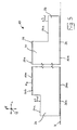
- FIG. 5 shows a view of the panel 10 similar to in FIG. 2
- the coupling means 24, 26 are shown only roughly-schematically, ie with a greatly simplified profile geometry.
- both coupling means 24, 26 each have precisely only one viewing section 24a, 26a whose surface normal n also runs parallel to the surface normal N of the visible surface 10b of the panel 10. It is true, as one can easily see, with the coupling means 24, 26, as they are in the FIG. 5 but also the others FIGS. 6 . 7 and 8th , are shown, no coupling can be effected.
- the simplified representation of these coupling means serves to clarify the problem described above and the inventive solution better. The principle explained below is also with more complex profile geometries, such as in the embodiments of the Figures 2 . 3 and 4 shown, applicable.
- FIG. 6 shows the panel 10 in the simplified representation according to FIG. 5 , as it is guided at a constant speed V P linearly in the longitudinal direction L of the panel 10 under a non-contact printing unit 36, which may be, for example, an inkjet printing unit. It has proven to be advantageous in practice to guide the panel 10 lying flat in the horizontal plane, while the printing unit 36 is disposed above this horizontal plane and usually extending parallel thereto (see. FIG. 8 ).
- the printing unit 36 is immovably mounted on a fixed frame and has a plurality of pressure nozzles (see. FIG. 8 ), of which in FIG. 6 only one pressure nozzle 36a is shown as an example.
- FIG. 6 a timeline t (pointing to the left) is plotted on this timeline, various times T1 to T5 are plotted, to which reference will be made in the course of the following discussion.
- the relative position of the printing unit 36 relative to the panel 10 is entered for two times T2, T4 of the printing process.
- the printing unit 36 first prints the viewing portion 26a of the coupling means 26 with a decoration indicated by a dot-and-dash line, then the visible surface 10b of the panel 10 with a dashed-dotted line indicated Decor and finally the viewing section 24a of the coupling means 24 with a direction indicated by a long stroke short line line decor.
- ink droplets leave the printing nozzles 36a of the printing unit 36 (in a reference frame resting on the printing unit 36) at a constant velocity V T in a direction perpendicular to the horizontal plane in which the panel is linearly guided.
- the ink droplets impinge not orthogonally but at an angle ⁇ on the viewing section 26a or the viewing section 10b or the viewing section 24a, which is smaller than 90 ° ,
- This angle ⁇ depends largely on the ratio between the speed V T of the ink, which is predetermined by the design of the printing unit 36, and the speed V P of the panel 10, which can be optionally adjusted from.
- the printing unit In order to print on the visible portion 26a of the coupling means 26, the printing unit starts the printing operation at a time T1, i. with a time advance ZV1 with respect to the outermost side edge 38 of the coupling means 26, which at time T1 is not yet vertically below the pressure nozzles 36a of the pressure unit 36.
- the size of this time delay ZV1 is dependent on the angle ⁇ and the distance H2 between the viewing section 26a and the pressure nozzle 36a.
- the printing unit 36 terminates the printing process for printing the viewing section 26a at a time T2, wherein the time T2 with respect to edge 40 has the time advance ZV1 already mentioned above.
- the lead time ZV2 for printing the viewing portion 10b which starts at the edge 42, smaller as the lead time ZV1. Consequently, the printing of the viewing section 10b need not be started until the time T3. So it comes to a break. If necessary, this break can also be used to also print the vertical flank between the viewing section 26a and the visible surface 10b.
- the entire visible surface 10b of the panel 10 is then printed, wherein the time T4 with respect to the edge 44, at which the visible surface 10b ends, the above-mentioned time lead ZV2 has.
- the printing unit 36 begins to print on the viewing section 24a of the coupling means 24 and continues this printing process until the edge 46 at which the viewing section 24a ends is reached at a time T5.
- the time advance ZV3, which can be assigned to the viewing section 24a is greater than the time advance ZV2.
- the printing of the viewing section 24a would therefore have to be started at a time at which the printing of the visible surface 10b is not yet completed. Of course this is not possible.
- the trailing coupling agent can therefore with the in FIG. 6 illustrated embodiment, the emergence of a "shadowed" portion S on the viewing portion 24a of the coupling means 24 can not be avoided.
- the size of the shaded portion S depends, in addition to the angle ⁇ , significantly on the difference between the distance H1 (distance between the visible surface 10b and pressure nozzle 36a) and the distance H3 (distance between the viewing section 24a and pressure nozzle 36a).
- the coupling means 24, 26, whose viewing portion 24a, 26a has the smaller distance H3, H2 to the pressure nozzle 36a, as to select the trailing coupling means and the respective other coupling means as the leading coupling means. For this reason (H2> H3) was according to FIG. 6 the coupling means 26 is selected as the leading coupling means and the coupling means 24 as the trailing coupling means.
- the relative speed between the ink and the panel 10 in the direction of movement of the panel 10 can be reduced, completely zeroed or even overcompensated. Overcompensation can be useful if the trailing coupling means has viewing sections that are located in undercuts, but should still be printed.
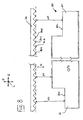
- FIG. 7 an arrangement of the printing unit 36 is shown in which the printing unit 36 is pivoted about the axis A to the extent that when the speed V T of the ink vectorially decomposed into a horizontal velocity component V TH and a vertical velocity component V TV , the amount and the direction of the horizontal velocity component V TH are identical to the magnitude and direction of the velocity V P of the panel.
- the time lapses ZV1, ZV2 and ZV3 are reduced to zero.
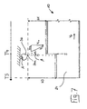
- the printing unit 36 includes a plurality of printing nozzles 36a, 36b, 36c, 36d, etc.
- FIG. 8 is a rough-schematic representation (with of FIG. 5 already known simplified profile geometry), the shows how the panel 10 can be printed on its entire transverse width Q at the same time by the printing nozzles 36a, 36b, 36c, 36d, etc., when it is passed under the printing unit 36.
- the coupling means 20, 22 on the respective side edges 12, 14 of the longitudinal sides L extending in the long sides of the panel 10 are the distances H4 and H5 between the respective viewing sections 22a, 20a of the coupling means 22, 20 and the above these viewing sections 22a 20a located pressure nozzles of the printing unit 36 to be considered.
- the possible coupling means of the panel 10 have a profile geometry, which is generally more complex than those which, for better illustration of the method according to the invention in FIG FIG. 5 has been described.
- the various viewing portions 20a, 22a, 24a, 26a of the coupling means 20, 22, 24, 26 need not all be parallel to the upper visible surface 10b of the panel 10 (see eg Figures 2 . 3, 4 Rather, if the respective viewing portions 20a, 22a, 24a, 26a are planar, they may be oblique or, if the viewing portions 20a, 22a, 24a, 26a are curved, have at least one radius of curvature.
- the respective viewing sections 20a, 22a, 24a, 26a may be viewed in an approximation, advantageously performed by the control unit, as a plurality of smaller viewing sections oriented approximately parallel to the viewing surface 10b of the panel 10, and thus have a well-defined distance to the corresponding printing nozzles of which the section is to be printed.
- the resolution of this subdivision is preferably based on the resolution of the printing unit 36.
- the printing of the viewing sections 20a, 22a, 24a, 26a always has certain limits depending on the geometry. This is especially true for viewing sections 20a, 22a, 24a, 26a, which are partially or entirely undercuts, so that ink from the printing unit 36 can hardly or not reach them (see, for example, the left viewing section 26a of the "angling" profile in FIG FIG. 2 or the viewing portion 26a “of the” snap “profile in FIG FIG. 4 ).
- the coupling means 24, 26 of the trailing or leading side edges 16, 18 of the above-described angle ⁇ , or possibly a pivot angle ⁇ of the printing unit 36 can be used about the axis A, to still print such viewing sections 24a, 26a within certain limits ,
Landscapes
- Engineering & Computer Science (AREA)
- Architecture (AREA)
- Manufacturing & Machinery (AREA)
- Civil Engineering (AREA)
- Structural Engineering (AREA)
- Printing Methods (AREA)
- Ink Jet (AREA)
- Accessory Devices And Overall Control Thereof (AREA)
- Pressure Welding/Diffusion-Bonding (AREA)
- Finishing Walls (AREA)
Priority Applications (2)
| Application Number | Priority Date | Filing Date | Title |
|---|---|---|---|
| SI200930189T SI2296903T1 (sl) | 2008-06-12 | 2009-06-10 | Postopek za tiskanje panela obloge |
| PL09756393T PL2296903T3 (pl) | 2008-06-12 | 2009-06-10 | Sposób zadrukowywania panelu okładzinowego |
Applications Claiming Priority (2)
| Application Number | Priority Date | Filing Date | Title |
|---|---|---|---|
| DE102008028000A DE102008028000A1 (de) | 2008-06-12 | 2008-06-12 | Verfahren zum Bedrucken eines Verkleidungspaneels |
| PCT/EP2009/057209 WO2009150185A1 (de) | 2008-06-12 | 2009-06-10 | Verfahren zum bedrucken eines verkleidungspaneels |
Publications (2)
| Publication Number | Publication Date |
|---|---|
| EP2296903A1 EP2296903A1 (de) | 2011-03-23 |
| EP2296903B1 true EP2296903B1 (de) | 2011-11-30 |
Family
ID=41067025
Family Applications (1)
| Application Number | Title | Priority Date | Filing Date |
|---|---|---|---|
| EP09756393A Not-in-force EP2296903B1 (de) | 2008-06-12 | 2009-06-10 | Verfahren zum bedrucken eines verkleidungspaneels |
Country Status (13)
| Country | Link |
|---|---|
| US (1) | US20100208019A1 (pl) |
| EP (1) | EP2296903B1 (pl) |
| CN (1) | CN101743126B (pl) |
| AT (1) | ATE535381T1 (pl) |
| CA (1) | CA2689077C (pl) |
| DE (1) | DE102008028000A1 (pl) |
| DK (1) | DK2296903T3 (pl) |
| ES (1) | ES2375443T3 (pl) |
| PL (1) | PL2296903T3 (pl) |
| PT (1) | PT2296903E (pl) |
| RU (1) | RU2413620C1 (pl) |
| SI (1) | SI2296903T1 (pl) |
| WO (1) | WO2009150185A1 (pl) |
Families Citing this family (7)
| Publication number | Priority date | Publication date | Assignee | Title |
|---|---|---|---|---|
| WO2013024145A1 (de) * | 2011-08-16 | 2013-02-21 | Dieffenbacher System-Automation Gmbh | Vorrichtung und verfahren zum bedrucken von oberflächen von werkstoffplatten mit einer mehrfarbigen abbildung |
| EP2708675A1 (de) * | 2012-09-17 | 2014-03-19 | Akzenta Paneele + Profile GmbH | Dekorpaneel |
| CA2997577A1 (en) * | 2015-09-17 | 2017-03-23 | Beaulieu International Group Nv | Custom-made covering panels by digital printing of base panels |
| AT520096B1 (de) * | 2017-08-14 | 2019-01-15 | Ifn Holding Ag | Verfahren zur Herstellung eines Fenster- oder Türprofils |
| JP7342564B2 (ja) * | 2019-09-20 | 2023-09-12 | カシオ計算機株式会社 | 印刷装置、印刷システム、印刷方法及びプログラム |
| US12195964B2 (en) | 2020-08-24 | 2025-01-14 | Huber Engineered Woods Llc | Tongue-and-groove panel for improved interpanel fit |
| WO2022251416A1 (en) * | 2021-05-27 | 2022-12-01 | Armstrong World Industries, Inc. | System and device for printing upon textured surfaces of building panels, and methods thereof |
Family Cites Families (13)
| Publication number | Priority date | Publication date | Assignee | Title |
|---|---|---|---|---|
| JPH1058668A (ja) * | 1996-08-15 | 1998-03-03 | Seiko Epson Corp | インクジェットプリンタおよびそのインク吐出タイミング補正方法 |
| JP3023333B2 (ja) * | 1997-06-30 | 2000-03-21 | ニチハ株式会社 | 建築板とその塗装方法 |
| PT1676720E (pt) * | 2000-06-13 | 2011-02-28 | Flooring Ind Ltd | Revestimento de pavimentos |
| US6755518B2 (en) * | 2001-08-30 | 2004-06-29 | L&P Property Management Company | Method and apparatus for ink jet printing on rigid panels |
| US7556690B2 (en) * | 2002-09-27 | 2009-07-07 | Brother Kogyo Kabushiki Kaisha | Nozzle head, nozzle head holder, and droplet jet patterning device |
| DE10323412B4 (de) * | 2003-05-23 | 2007-07-05 | Bauer, Jörg R. | Verfahren und Vorrichtung zum Herstellen eines Bauteils mit einer Oberfläche vorbestimmten Aussehens |
| BRPI0519338A2 (pt) * | 2004-12-16 | 2009-01-20 | Flooring Ind Ltd | painel de piso e mÉtodo para fabricar um painel de piso |
| DE102005001630A1 (de) * | 2005-01-12 | 2006-07-20 | Akzenta Paneele + Profile Gmbh | Fußbodenpaneel |
| KR100677579B1 (ko) * | 2005-04-26 | 2007-02-02 | 삼성전자주식회사 | 잉크젯 화상형성장치 |
| DE102005042658B3 (de) * | 2005-09-08 | 2007-03-01 | Kronotec Ag | Bauplatte, insbesondere Fußbodenpaneel |
| DE102005060753A1 (de) * | 2005-12-16 | 2007-06-21 | Kronotec Ag | Verfahren und Anlage zum Bedrucken von mindestens einem profilierten Abschnitt eines Paneels |
| US7918062B2 (en) * | 2006-06-08 | 2011-04-05 | Mannington Mills, Inc. | Methods and systems for decorating bevel and other surfaces of laminated floorings |
| DE102006034060B4 (de) * | 2006-07-20 | 2009-01-15 | Ball Packaging Europe Gmbh | Verfahren und Vorrichtung zum Dekorieren einer unebenen Fläche an einem formstabilen Objekt |
-
2008
- 2008-06-12 DE DE102008028000A patent/DE102008028000A1/de not_active Withdrawn
-
2009
- 2009-06-10 WO PCT/EP2009/057209 patent/WO2009150185A1/de not_active Ceased
- 2009-06-10 AT AT09756393T patent/ATE535381T1/de active
- 2009-06-10 PT PT09756393T patent/PT2296903E/pt unknown
- 2009-06-10 US US12/602,377 patent/US20100208019A1/en not_active Abandoned
- 2009-06-10 EP EP09756393A patent/EP2296903B1/de not_active Not-in-force
- 2009-06-10 DK DK09756393.6T patent/DK2296903T3/da active
- 2009-06-10 ES ES09756393T patent/ES2375443T3/es active Active
- 2009-06-10 CN CN200980000548.3A patent/CN101743126B/zh not_active Expired - Fee Related
- 2009-06-10 SI SI200930189T patent/SI2296903T1/sl unknown
- 2009-06-10 CA CA2689077A patent/CA2689077C/en not_active Expired - Fee Related
- 2009-06-10 PL PL09756393T patent/PL2296903T3/pl unknown
- 2009-06-10 RU RU2009147445/12A patent/RU2413620C1/ru not_active IP Right Cessation
Also Published As
| Publication number | Publication date |
|---|---|
| PT2296903E (pt) | 2012-01-16 |
| EP2296903A1 (de) | 2011-03-23 |
| ATE535381T1 (de) | 2011-12-15 |
| CA2689077C (en) | 2016-04-26 |
| RU2413620C1 (ru) | 2011-03-10 |
| DE102008028000A1 (de) | 2009-12-17 |
| CN101743126A (zh) | 2010-06-16 |
| ES2375443T3 (es) | 2012-02-29 |
| WO2009150185A1 (de) | 2009-12-17 |
| PL2296903T3 (pl) | 2012-04-30 |
| CA2689077A1 (en) | 2009-12-17 |
| CN101743126B (zh) | 2014-04-09 |
| DK2296903T3 (da) | 2012-03-19 |
| US20100208019A1 (en) | 2010-08-19 |
| SI2296903T1 (sl) | 2012-04-30 |
Similar Documents
| Publication | Publication Date | Title |
|---|---|---|
| EP2296903B1 (de) | Verfahren zum bedrucken eines verkleidungspaneels | |
| EP2593244B1 (de) | Verfahren zum herstellen eines ein dekor und eine dreidimensionale struktur aufweisenden paneels | |
| DE10323412B4 (de) | Verfahren und Vorrichtung zum Herstellen eines Bauteils mit einer Oberfläche vorbestimmten Aussehens | |
| EP2133154B1 (de) | Verfahren, Vorrichtung und System zum Herstellen von Bauteilen mit vorbestimmtem Oberflächenaussehen, insbesondere von Frontplatten von Küchenelementen | |
| DE102009043812B4 (de) | Verfahren zum Herstellen einer bedruckten Oberfläche auf einem flächigen Werkstück | |
| EP1862304B1 (de) | Verfahren zum Erzeugen eines Oberflächendekors auf einem Paneel und Druckmaschine zur Durchführung des Verfahrens | |
| WO2008067933A1 (de) | Verfahren und vorrichtung zum erzeugen individualisierter oberflächen durch bedrucken mit wenigstens einem aus einem urmuster hergeleiteten individuellen einzelmuster | |
| EP3458240B1 (de) | Vorrichtung und verfahren zum anbringen eines kantenprofils sowie möbelteil | |
| EP2955295B1 (de) | Verfahren zum Herstellen eines Paneels | |
| EP2572896B1 (de) | Vorrichtung zum Veredeln eines Paneels | |
| EP2873535A1 (de) | Werkstücke mit oberflächenstrukturierter Dekoroberfläche | |
| DE102007061035A1 (de) | Verkleidungspaneel und daraus gebildete Verkleidung | |
| WO2017198550A1 (de) | Verfahren zum herstellen eines kantenprofils und möbelteil | |
| EP2082898B1 (de) | Druckwalze und Verfahren zum Aufbringen eines Dekors auf ein Plattenelement | |
| EP1973752B1 (de) | Wand-, decken- oder fussbodenpaneele | |
| EP3234280A1 (de) | Paneel und eine mehrzahl derartiger paneele umfassendes paneelgebinde | |
| EP3656566B1 (de) | Verfahren zum bedrucken von länglichen profilleisten und profilleisten | |
| EP1886778B1 (de) | Verfahren und Vorrichtung zur Herstellung von Laminatpaneelen | |
| DE19963084A1 (de) | Zierlaminat | |
| DE102023105733A1 (de) | Akustikelement und Verfahren zum Herstellen eines Akustikelements | |
| EP3433109B1 (de) | Verfahren zur herstellung eines laminats | |
| EP4440804B1 (de) | Verfahren und druckervorrichtung zum herstellen eines presswerkzeugs | |
| AT520096B1 (de) | Verfahren zur Herstellung eines Fenster- oder Türprofils | |
| EP2532804B1 (de) | Verfahren zur Herstellung eines Paneels für einen Boden-, Wand- und/oder Deckenbelag | |
| EP4461547A1 (de) | Verfahren zum bedrucken eines beschichtungsmaterials sowie system |
Legal Events
| Date | Code | Title | Description |
|---|---|---|---|
| PUAI | Public reference made under article 153(3) epc to a published international application that has entered the european phase |
Free format text: ORIGINAL CODE: 0009012 |
|
| 17P | Request for examination filed |
Effective date: 20091207 |
|
| AK | Designated contracting states |
Kind code of ref document: A1 Designated state(s): AT BE BG CH CY CZ DE DK EE ES FI FR GB GR HR HU IE IS IT LI LT LU LV MC MK MT NL NO PL PT RO SE SI SK TR |
|
| AX | Request for extension of the european patent |
Extension state: AL BA RS |
|
| GRAP | Despatch of communication of intention to grant a patent |
Free format text: ORIGINAL CODE: EPIDOSNIGR1 |
|
| DAX | Request for extension of the european patent (deleted) | ||
| GRAS | Grant fee paid |
Free format text: ORIGINAL CODE: EPIDOSNIGR3 |
|
| GRAA | (expected) grant |
Free format text: ORIGINAL CODE: 0009210 |
|
| RIN1 | Information on inventor provided before grant (corrected) |
Inventor name: SCHNIEP, JOCHEN |
|
| AK | Designated contracting states |
Kind code of ref document: B1 Designated state(s): AT BE BG CH CY CZ DE DK EE ES FI FR GB GR HR HU IE IS IT LI LT LU LV MC MK MT NL NO PL PT RO SE SI SK TR |
|
| REG | Reference to a national code |
Ref country code: CH Ref legal event code: NV Representative=s name: BOHEST AG Ref country code: CH Ref legal event code: EP Ref country code: GB Ref legal event code: FG4D Free format text: NOT ENGLISH |
|
| RIN1 | Information on inventor provided before grant (corrected) |
Inventor name: SCHNIEPP, JOCHEN |
|
| REG | Reference to a national code |
Ref country code: IE Ref legal event code: FG4D Free format text: LANGUAGE OF EP DOCUMENT: GERMAN |
|
| REG | Reference to a national code |
Ref country code: PT Ref legal event code: SC4A Free format text: AVAILABILITY OF NATIONAL TRANSLATION Effective date: 20120103 |
|
| REG | Reference to a national code |
Ref country code: DE Ref legal event code: R096 Ref document number: 502009002082 Country of ref document: DE Effective date: 20120209 |
|
| REG | Reference to a national code |
Ref country code: RO Ref legal event code: EPE |
|
| REG | Reference to a national code |
Ref country code: NL Ref legal event code: T3 Ref country code: ES Ref legal event code: FG2A Ref document number: 2375443 Country of ref document: ES Kind code of ref document: T3 Effective date: 20120229 |
|
| REG | Reference to a national code |
Ref country code: DK Ref legal event code: T3 |
|
| LTIE | Lt: invalidation of european patent or patent extension |
Effective date: 20111130 |
|
| PG25 | Lapsed in a contracting state [announced via postgrant information from national office to epo] |
Ref country code: LT Free format text: LAPSE BECAUSE OF FAILURE TO SUBMIT A TRANSLATION OF THE DESCRIPTION OR TO PAY THE FEE WITHIN THE PRESCRIBED TIME-LIMIT Effective date: 20111130 Ref country code: NO Free format text: LAPSE BECAUSE OF FAILURE TO SUBMIT A TRANSLATION OF THE DESCRIPTION OR TO PAY THE FEE WITHIN THE PRESCRIBED TIME-LIMIT Effective date: 20120229 Ref country code: IS Free format text: LAPSE BECAUSE OF FAILURE TO SUBMIT A TRANSLATION OF THE DESCRIPTION OR TO PAY THE FEE WITHIN THE PRESCRIBED TIME-LIMIT Effective date: 20120330 |
|
| REG | Reference to a national code |
Ref country code: PL Ref legal event code: T3 |
|
| REG | Reference to a national code |
Ref country code: SK Ref legal event code: T3 Ref document number: E 11187 Country of ref document: SK |
|
| PG25 | Lapsed in a contracting state [announced via postgrant information from national office to epo] |
Ref country code: SE Free format text: LAPSE BECAUSE OF FAILURE TO SUBMIT A TRANSLATION OF THE DESCRIPTION OR TO PAY THE FEE WITHIN THE PRESCRIBED TIME-LIMIT Effective date: 20111130 Ref country code: LV Free format text: LAPSE BECAUSE OF FAILURE TO SUBMIT A TRANSLATION OF THE DESCRIPTION OR TO PAY THE FEE WITHIN THE PRESCRIBED TIME-LIMIT Effective date: 20111130 Ref country code: GR Free format text: LAPSE BECAUSE OF FAILURE TO SUBMIT A TRANSLATION OF THE DESCRIPTION OR TO PAY THE FEE WITHIN THE PRESCRIBED TIME-LIMIT Effective date: 20120301 Ref country code: HR Free format text: LAPSE BECAUSE OF FAILURE TO SUBMIT A TRANSLATION OF THE DESCRIPTION OR TO PAY THE FEE WITHIN THE PRESCRIBED TIME-LIMIT Effective date: 20111130 |
|
| REG | Reference to a national code |
Ref country code: IE Ref legal event code: FD4D |
|
| PG25 | Lapsed in a contracting state [announced via postgrant information from national office to epo] |
Ref country code: CY Free format text: LAPSE BECAUSE OF FAILURE TO SUBMIT A TRANSLATION OF THE DESCRIPTION OR TO PAY THE FEE WITHIN THE PRESCRIBED TIME-LIMIT Effective date: 20111130 |
|
| PG25 | Lapsed in a contracting state [announced via postgrant information from national office to epo] |
Ref country code: BG Free format text: LAPSE BECAUSE OF FAILURE TO SUBMIT A TRANSLATION OF THE DESCRIPTION OR TO PAY THE FEE WITHIN THE PRESCRIBED TIME-LIMIT Effective date: 20120229 Ref country code: IE Free format text: LAPSE BECAUSE OF FAILURE TO SUBMIT A TRANSLATION OF THE DESCRIPTION OR TO PAY THE FEE WITHIN THE PRESCRIBED TIME-LIMIT Effective date: 20111130 Ref country code: EE Free format text: LAPSE BECAUSE OF FAILURE TO SUBMIT A TRANSLATION OF THE DESCRIPTION OR TO PAY THE FEE WITHIN THE PRESCRIBED TIME-LIMIT Effective date: 20111130 |
|
| PLBE | No opposition filed within time limit |
Free format text: ORIGINAL CODE: 0009261 |
|
| STAA | Information on the status of an ep patent application or granted ep patent |
Free format text: STATUS: NO OPPOSITION FILED WITHIN TIME LIMIT |
|
| 26N | No opposition filed |
Effective date: 20120831 |
|
| REG | Reference to a national code |
Ref country code: HU Ref legal event code: AG4A Ref document number: E014546 Country of ref document: HU |
|
| REG | Reference to a national code |
Ref country code: DE Ref legal event code: R097 Ref document number: 502009002082 Country of ref document: DE Effective date: 20120831 |
|
| PG25 | Lapsed in a contracting state [announced via postgrant information from national office to epo] |
Ref country code: MC Free format text: LAPSE BECAUSE OF NON-PAYMENT OF DUE FEES Effective date: 20120630 |
|
| PG25 | Lapsed in a contracting state [announced via postgrant information from national office to epo] |
Ref country code: MK Free format text: LAPSE BECAUSE OF FAILURE TO SUBMIT A TRANSLATION OF THE DESCRIPTION OR TO PAY THE FEE WITHIN THE PRESCRIBED TIME-LIMIT Effective date: 20111130 |
|
| PG25 | Lapsed in a contracting state [announced via postgrant information from national office to epo] |
Ref country code: FI Free format text: LAPSE BECAUSE OF FAILURE TO SUBMIT A TRANSLATION OF THE DESCRIPTION OR TO PAY THE FEE WITHIN THE PRESCRIBED TIME-LIMIT Effective date: 20111130 |
|
| PG25 | Lapsed in a contracting state [announced via postgrant information from national office to epo] |
Ref country code: MT Free format text: LAPSE BECAUSE OF FAILURE TO SUBMIT A TRANSLATION OF THE DESCRIPTION OR TO PAY THE FEE WITHIN THE PRESCRIBED TIME-LIMIT Effective date: 20111130 |
|
| PGFP | Annual fee paid to national office [announced via postgrant information from national office to epo] |
Ref country code: DK Payment date: 20131010 Year of fee payment: 5 |
|
| PGFP | Annual fee paid to national office [announced via postgrant information from national office to epo] |
Ref country code: HU Payment date: 20131004 Year of fee payment: 5 |
|
| REG | Reference to a national code |
Ref country code: CH Ref legal event code: PCAR Free format text: NEW ADDRESS: HOLBEINSTRASSE 36-38, 4051 BASEL (CH) |
|
| REG | Reference to a national code |
Ref country code: DK Ref legal event code: EBP Effective date: 20140630 |
|
| PG25 | Lapsed in a contracting state [announced via postgrant information from national office to epo] |
Ref country code: HU Free format text: LAPSE BECAUSE OF NON-PAYMENT OF DUE FEES Effective date: 20140611 |
|
| PG25 | Lapsed in a contracting state [announced via postgrant information from national office to epo] |
Ref country code: DK Free format text: LAPSE BECAUSE OF NON-PAYMENT OF DUE FEES Effective date: 20140630 |
|
| REG | Reference to a national code |
Ref country code: FR Ref legal event code: PLFP Year of fee payment: 8 |
|
| REG | Reference to a national code |
Ref country code: FR Ref legal event code: PLFP Year of fee payment: 9 |
|
| REG | Reference to a national code |
Ref country code: FR Ref legal event code: PLFP Year of fee payment: 10 |
|
| PGFP | Annual fee paid to national office [announced via postgrant information from national office to epo] |
Ref country code: DE Payment date: 20190415 Year of fee payment: 11 Ref country code: IT Payment date: 20190624 Year of fee payment: 11 Ref country code: PT Payment date: 20190604 Year of fee payment: 11 Ref country code: PL Payment date: 20190529 Year of fee payment: 11 Ref country code: NL Payment date: 20190619 Year of fee payment: 11 Ref country code: LU Payment date: 20190619 Year of fee payment: 11 Ref country code: CZ Payment date: 20190610 Year of fee payment: 11 |
|
| PGFP | Annual fee paid to national office [announced via postgrant information from national office to epo] |
Ref country code: BE Payment date: 20190619 Year of fee payment: 11 Ref country code: SI Payment date: 20190521 Year of fee payment: 11 Ref country code: TR Payment date: 20190528 Year of fee payment: 11 |
|
| PGFP | Annual fee paid to national office [announced via postgrant information from national office to epo] |
Ref country code: SK Payment date: 20190528 Year of fee payment: 11 Ref country code: CH Payment date: 20190619 Year of fee payment: 11 |
|
| PGFP | Annual fee paid to national office [announced via postgrant information from national office to epo] |
Ref country code: AT Payment date: 20190621 Year of fee payment: 11 Ref country code: ES Payment date: 20190719 Year of fee payment: 11 Ref country code: GB Payment date: 20190619 Year of fee payment: 11 |
|
| REG | Reference to a national code |
Ref country code: DE Ref legal event code: R231 Ref document number: 502009002082 Country of ref document: DE |
|
| PG25 | Lapsed in a contracting state [announced via postgrant information from national office to epo] |
Ref country code: DE Free format text: LAPSE BECAUSE OF THE APPLICANT RENOUNCES Effective date: 20200505 |
|
| PGFP | Annual fee paid to national office [announced via postgrant information from national office to epo] |
Ref country code: RO Payment date: 20200421 Year of fee payment: 12 |
|
| PG25 | Lapsed in a contracting state [announced via postgrant information from national office to epo] |
Ref country code: PT Free format text: LAPSE BECAUSE OF NON-PAYMENT OF DUE FEES Effective date: 20201210 Ref country code: CZ Free format text: LAPSE BECAUSE OF NON-PAYMENT OF DUE FEES Effective date: 20200610 |
|
| REG | Reference to a national code |
Ref country code: CH Ref legal event code: PL |
|
| REG | Reference to a national code |
Ref country code: NL Ref legal event code: MM Effective date: 20200701 |
|
| REG | Reference to a national code |
Ref country code: SK Ref legal event code: MM4A Ref document number: E 11187 Country of ref document: SK Effective date: 20200610 |
|
| REG | Reference to a national code |
Ref country code: AT Ref legal event code: MM01 Ref document number: 535381 Country of ref document: AT Kind code of ref document: T Effective date: 20200610 |
|
| GBPC | Gb: european patent ceased through non-payment of renewal fee |
Effective date: 20200610 |
|
| PG25 | Lapsed in a contracting state [announced via postgrant information from national office to epo] |
Ref country code: LU Free format text: LAPSE BECAUSE OF NON-PAYMENT OF DUE FEES Effective date: 20200610 |
|
| REG | Reference to a national code |
Ref country code: BE Ref legal event code: MM Effective date: 20200630 |
|
| PG25 | Lapsed in a contracting state [announced via postgrant information from national office to epo] |
Ref country code: PT Free format text: LAPSE BECAUSE OF NON-PAYMENT OF DUE FEES Effective date: 20210114 Ref country code: NL Free format text: LAPSE BECAUSE OF NON-PAYMENT OF DUE FEES Effective date: 20200701 Ref country code: GB Free format text: LAPSE BECAUSE OF NON-PAYMENT OF DUE FEES Effective date: 20200610 Ref country code: FR Free format text: LAPSE BECAUSE OF NON-PAYMENT OF DUE FEES Effective date: 20200630 Ref country code: LI Free format text: LAPSE BECAUSE OF NON-PAYMENT OF DUE FEES Effective date: 20200630 Ref country code: CH Free format text: LAPSE BECAUSE OF NON-PAYMENT OF DUE FEES Effective date: 20200630 |
|
| REG | Reference to a national code |
Ref country code: SI Ref legal event code: KO00 Effective date: 20210317 |
|
| PG25 | Lapsed in a contracting state [announced via postgrant information from national office to epo] |
Ref country code: BE Free format text: LAPSE BECAUSE OF NON-PAYMENT OF DUE FEES Effective date: 20200630 Ref country code: AT Free format text: LAPSE BECAUSE OF NON-PAYMENT OF DUE FEES Effective date: 20200610 Ref country code: SI Free format text: LAPSE BECAUSE OF NON-PAYMENT OF DUE FEES Effective date: 20200611 |
|
| PG25 | Lapsed in a contracting state [announced via postgrant information from national office to epo] |
Ref country code: SK Free format text: LAPSE BECAUSE OF NON-PAYMENT OF DUE FEES Effective date: 20200610 |
|
| PG25 | Lapsed in a contracting state [announced via postgrant information from national office to epo] |
Ref country code: IT Free format text: LAPSE BECAUSE OF NON-PAYMENT OF DUE FEES Effective date: 20200610 |
|
| PG25 | Lapsed in a contracting state [announced via postgrant information from national office to epo] |
Ref country code: RO Free format text: LAPSE BECAUSE OF NON-PAYMENT OF DUE FEES Effective date: 20210610 Ref country code: ES Free format text: LAPSE BECAUSE OF NON-PAYMENT OF DUE FEES Effective date: 20200611 |
|
| PG25 | Lapsed in a contracting state [announced via postgrant information from national office to epo] |
Ref country code: TR Free format text: LAPSE BECAUSE OF NON-PAYMENT OF DUE FEES Effective date: 20200610 |
|
| PG25 | Lapsed in a contracting state [announced via postgrant information from national office to epo] |
Ref country code: PL Free format text: LAPSE BECAUSE OF NON-PAYMENT OF DUE FEES Effective date: 20200610 |