EP2297540B1 - Dispositif capacitif et procédé de transport électrostatique de fluides diélectriques et ferroélectriques - Google Patents
Dispositif capacitif et procédé de transport électrostatique de fluides diélectriques et ferroélectriques Download PDFInfo
- Publication number
- EP2297540B1 EP2297540B1 EP09779702.1A EP09779702A EP2297540B1 EP 2297540 B1 EP2297540 B1 EP 2297540B1 EP 09779702 A EP09779702 A EP 09779702A EP 2297540 B1 EP2297540 B1 EP 2297540B1
- Authority
- EP
- European Patent Office
- Prior art keywords
- fluid
- electrodes
- electrode
- permittivity
- advancing
- Prior art date
- Legal status (The legal status is an assumption and is not a legal conclusion. Google has not performed a legal analysis and makes no representation as to the accuracy of the status listed.)
- Active
Links
Images








Classifications
-
- F—MECHANICAL ENGINEERING; LIGHTING; HEATING; WEAPONS; BLASTING
- F28—HEAT EXCHANGE IN GENERAL
- F28F—DETAILS OF HEAT-EXCHANGE AND HEAT-TRANSFER APPARATUS, OF GENERAL APPLICATION
- F28F13/00—Arrangements for modifying heat-transfer, e.g. increasing, decreasing
- F28F13/16—Arrangements for modifying heat-transfer, e.g. increasing, decreasing by applying an electrostatic field to the body of the heat-exchange medium
-
- F—MECHANICAL ENGINEERING; LIGHTING; HEATING; WEAPONS; BLASTING
- F04—POSITIVE - DISPLACEMENT MACHINES FOR LIQUIDS; PUMPS FOR LIQUIDS OR ELASTIC FLUIDS
- F04B—POSITIVE-DISPLACEMENT MACHINES FOR LIQUIDS; PUMPS
- F04B19/00—Machines or pumps having pertinent characteristics not provided for in, or of interest apart from, groups F04B1/00 - F04B17/00
- F04B19/006—Micropumps
-
- F—MECHANICAL ENGINEERING; LIGHTING; HEATING; WEAPONS; BLASTING
- F28—HEAT EXCHANGE IN GENERAL
- F28D—HEAT-EXCHANGE APPARATUS, NOT PROVIDED FOR IN ANOTHER SUBCLASS, IN WHICH THE HEAT-EXCHANGE MEDIA DO NOT COME INTO DIRECT CONTACT
- F28D15/00—Heat-exchange apparatus with the intermediate heat-transfer medium in closed tubes passing into or through the conduit walls ; Heat-exchange apparatus employing intermediate heat-transfer medium or bodies
Definitions
- the invention relates to a device and a method for conveying fluid media.
- the driven by pumps or blowers (forced) coolant circulation requires compared to the passive heat transfer by thermal diffusion increased design effort.
- electrical or mechanical drive power is absorbed and thus increases the total power loss.
- Cooling of power electronic components such as output stage transistors and voltage transformers and highly integrated microcomputers and other digital circuits (ASICs) is widely used in operation at high clock rates by circulation of air or water by means of positive displacement or turbopumps (blowers), especially in the case of high local power dissipation densities and thermally unfavorable operating environments , Be beside water or air
- turbopumps blowwers
- the passive fluid circulation according to the principle of self-sustaining convection, especially the widespread in the field of computer electronics "heat pipe". It is a hermetic system for heat transfer by means of evaporative cooling and self-sustaining coolant convection.
- the boiling temperature of the fluid used is in the thermal operating range of the heat source to be cooled.
- the liquid phase wets the inner wall of a thin tube, the gas phase can flow driven by the vapor pressure inside the tube to the heat sink and transfer the heat of vaporization there by condensation on a heat exchanger.
- the thickness of the liquid layer wetting the inner tube wall is limited by the capillary effect, which allows only relatively small tube diameter and thus limits the heat flow cross section of the heat pipe.
- thermoelectric Peltier elements based on the thermoelectric Peltier effect
- Such elements consist of two interconnected semiconductors whose conduction band lower edges are at different energy levels. If an electrical voltage is present across the boundary layer between the semiconductors, so that an electric current flows from the semiconductor with the energetically higher conduction band edge (heat source) to the semiconductor with the energetically lower conduction band edge (heat sink), a heat flow from the heat source also comes with the electrical conduction current sinking. The electrons that pass from the heat source into the heat sink transmit a part of their in the. By relaxation to the lower conduction band lower edge Heat source absorbed thermal excitation energy on the crystal lattice of the heat sink.
- thermoelectrically induced heat flow counteracts the heat diffusion, in addition, unavoidable ohmic losses heat the semiconducting materials.
- the thermal efficiency of Peltier elements is therefore low in relation to other known cooling mechanisms. In addition, they may take up more space than the electronic components to be cooled themselves. Peltier elements are also relatively expensive and are therefore generally not suitable for widespread use.
- the publication US 4,396,055 A relates to an apparatus according to the preamble of claim 10 for conveying a dielectric fluid in a heat pipe along a flow path.
- an apparatus for conveying at least one heat exchange medium having at least a first fluid having a first permittivity and at least a second fluid having a second permittivity different from the permittivity of the first fluid wherein the first fluid in the liquid phase does not mix with the second fluid in the liquid phase, whereby at least one dielectric interface is established between the first and second fluids.
- the at least two fluids of different permittivity thus form a layered dielectric and may consist of homogeneous substances or substance mixtures or be composed of inhomogeneous mixtures such as emulsions or suspensions.
- the device according to the invention comprises a capacitive arrangement which has at least two adjacent electrodes, in whose interspaces at least one flow channel extends, in which the at least one heat exchange medium flows.
- each electrode is provided with exactly one electrical voltage source of a voltage control device or with exactly one electric charge source of a charge control device each electrode can be charged and discharged independently of the other electrodes.
- the excitation of at least one electric field is provided by means of the electrode arrangement according to the invention in at least one flow channel, wherein the field is excited in the heat exchange medium in particular in the environments of dielectric interfaces of at least two fluids of different permittivity.
- the electric field induces feed forces in the environments of the dielectric interfaces which act in the direction of increasing the capacitance of the field-exciting electrodes.
- the fluid portions of higher permittivity seek into the field-filled interstices of the electrodes and displace the fluid portions of lower permittivity whereby the heat exchange medium advances in the direction of advancing forces due to cohesive forces in the fluids as a whole.
- This effect is achieved both with the voltage and charge of the field-conducting electrodes being fixed and is independent of the local orientation of the electric field vector, since the molecular dipole moments of dielectric fluids and ferroelectric colloids are preferably parallel to the local electric field apart from thermal fluctuations (orientation polarization) ).
- a method for determining the capacitance of field-exciting electrodes (capacitance matrix) and furthermore for determining the position of dielectric interfaces between fluids of different permittivity is provided.
- a capacitive measuring device is connected, such as a capacitive measuring bridge.
- the movement of a dielectric interface due to the electric feed field changes the capacitance of those field-exciting electrodes, in the influence of which the dielectric interface lies.
- the voltage control device the voltages applied to the field-exciting electrodes are varied. If this changes the capacitance of the electrodes, then there is a dielectric interface in the electrode gap.
- the capacity (capacitance matrix) of the field-exciting electrodes with a homogeneous and layered dielectric can be found empirically or by numerical methods, in the case of a simple or symmetrical electrode geometry as in the case of a plate capacitor or circular cylindrical capacitor also be known analytically.
- the method by means of progressive, voltage or charge controlled charging and discharging of the electrode assembly according to the invention causes a propagating in the advancing direction excitation of an electric field in at least one flow channel of the at least one heat exchange medium, in particular in areas of dielectric interfaces between the at least two Fluids of different permittivity contained in the heat exchange medium.
- the electrode assembly maintains an electrical field excitation leading the dielectric interfaces in the advancing direction until the advancing forces have decayed and the capacitance of the field-exciting electrodes no longer increases.
- the charges are now transferred with the voltage or charge control device to the adjacent electrodes in the feed direction, which may be connected in parallel to increase their capacity, and carried out the next feed step.
- the feed method by means of a voltage or charge control device progressively charges only those electrodes in whose interstices dielectric interfaces are found with the above-described method for determining the capacitance.
- the electrical field excitation is energetically favorable limited to the environments of the interfaces, since only there act feed forces on the heat exchange medium.
- the electric feed field is locally energized and maintained until the capacitance of the field-exciting electrodes no longer increases and the affected dielectric interface no longer progresses, thus ending the feed step.
- the feed steps with temporarily held voltages to the Electrode terminals or temporarily held charges carried on the electrodes.
- the voltage or charge control device superimposed on the progressively excited electric feed field a static electric field, which counteracts the escape of the dielectric fluids contained in the heat exchange medium from the device according to the invention, if the permittivity of the medium surrounding the device according to the invention is less than the permittivity the fluids in the heat exchange medium.
- At least one of the fluids of the heat exchange medium consists of a homogeneous ferroelectric substance, in particular a ferroelectric liquid crystal, or of a suspension or emulsion containing ferroelectric colloids.
- the heat exchange medium has at least one first fluid section, which consists of the liquid phase of a dielectric fluid, and at least one further fluid section, which consists of the vapor phase of this first fluid.
- the boiling temperature of at least one of the fluids contained in the heat exchange medium is in the thermal operating range of the at least one heat source to be cooled or the at least one heat sink to be heated.
- a method for determining the flow velocity of at least one dielectric interface between fluid sections of different permittivity, wherein the temporal change of the capacitance of field-exciting electrodes, in the interspace of which is a flowing with the heat exchange medium dielectric interface is determined.
- a method which by means of temporal correlation of the capacitance variation of different electrodes, in whose interspaces dielectric interfaces between fluid sections of different permittivity have penetrated, the length of homogeneous fluid sections is determined.
- a method for determining the fluid density and fluid temperature is provided.
- those field-exciting electrodes are found whose interspace fills a homogeneous fluid section of the heat exchange medium.
- the measured capacitance depends only on the temperature-dependent dielectric orientation polarization of the fluid.
- the relationship between temperature and polarization in fluids with permanent molecular dipole moment, such as water, is known by the Debye equation, for those with induced dipole moment by the Clausius-Mossotti equation.
- the functional relationship between the measured capacitance of the electrodes and the dielectric polarization and temperature of the dielectric fluid is shown as a numerical algorithm in the program of a microcomputer.
- the numerical algorithm in the program sequence of this computer determines the heat flow through the field-generating electrode arrangement from the measured capacitance and the temperature of the homogeneous fluid section enclosed by the electrodes together with the flow velocity determined according to the invention and the known specific heat capacity of the fluid.
- the embodiments of the device according to the invention are particularly suitable for electrostatic convection drive dielectric and ferroelectric fluids and are advantageous for use in convection circuits for cooling or heating of electrical, electronic or micromechanical assemblies in engine and transmission control units of Motor vehicles and machinery that must meet high standards of robustness, maintenance and durability.
- the embodiments of the device according to the invention are suitable for use in mobile, electronic terminals such as laptops, PDAs, etc., whose batteries have low charge capacity and do not allow a power-consuming, electrically drivenméungskonvetation using pumps or blowers.
- the invention is suitable as an additional drive for circulating the liquid phase of the heat exchange medium in a heat pipe (heat pipe) with self-sustaining convection.
- the electrodes and flow channels of the device according to the invention are suitable in miniaturized form for embedding in multilayer electronic printed circuit boards or ceramic substrates; the electrodes may be interconnected with the electronic assemblies and used as capacitors of variable capacitance in the microelectronic or mechanical assemblies to be cooled or heated.
- Embodiments of the invention with a one-piece outer electrode which is designed as a closed outer wall of the flow channel, are completely shielded electromagnetically.
- the signal integrity of electronic components and interconnects is not affected, there is no electromagnetic interference at the electrodes during the transient excitation of the electric feed field.
- Figures 1 to 23 each show sections of embodiments of the device according to the invention in longitudinal section along the feed direction of the heat exchange medium again.
- illustration 1 shows a first embodiment 1 of the device according to the invention for conveying a heat exchange medium 2, the first dielectric fluid portion 3 'with a first permittivity ⁇ 1 , a second dielectric fluid portion 4' with a second permittivity ⁇ 2 and a third dielectric fluid portion 5 'with a third Permittivity ⁇ 3 , wherein the second permittivity ⁇ 2 of the third and first permittivity ⁇ 3 , ⁇ 1 is different.
- the non-mixing fluids 3, 4 and 5 form dielectric interfaces 16 and thus in the flow direction of the heat exchange medium second layered dielectric.
- a one-piece, closed outer electrode 12 is provided, which is formed as an outer wall 12 'of a flow channel 6 and individual, separate inner electrodes 7, 8, 9 and 10 encloses, which are arranged along the feed direction and form a multi-part designed inner electrode 11.
- the outer electrode 12 and the inner electrode 11 are galvanically separated from each other.
- the outer electrode 12 and the inner electrodes 7, 8, 9, 10 of an electrode assembly 14 have gaps forming the flow channel 6 in which the heat exchange medium 2 flows.
- a first plate-shaped outer electrode 12 and a second plate-shaped, separated from the outer electrode 12 outer electrode 13 are provided. Furthermore, the internal electrodes 7, 8, 9, 10 are plate-shaped and separated from the external electrodes 12 and 13.
- the outer electrodes 12 and 13 are designed as outer walls 12 ', 13' of the flow channel 6, which receives the heat exchange medium 2. The other outer walls of the flow channel 6 parallel to the paper plane are in the sectional view illustration 1 not shown.
- Figure 2 shows the first embodiment 1, wherein it is associated with an electronic voltage control device 17, which has independently controlled electrical voltage sources U 0 , U 1 , U 2 , U 3 and U 4 .
- Each of these voltage sources U 0 , U 1 , U 2 , U 3 and U 4 is electrically connected via a single line 21 with exactly one of the internal electrodes 7, 8, 9, 10.
- the electrodes 7, 8, 9, 10 can be charged and discharged independently of each other.
- the outer electrodes 12 and 13 are electrically connected to a ground potential 18.
- each of the internal electrodes 7, 8, 9, 10 is connected via separate individual lines 21 to exactly one of the charge sources of an electronic charge control device 20.
- the electrode assembly 14 may be interconnected by means of the voltage control device 17 or the charge control device 20 to a capacitive capacitive network (capacitance matrix).
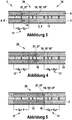
- FIGS 3 to 8 show successive advancing steps 24, 25, 26 of a first embodiment of the method according to the invention in the first embodiment 1 of the device with the local excitation of an electric feed field 19 by means of voltage or charge controlled charging and discharging of the field exciting electrode assembly 14.
- the local electrical field excitation 19 "remains at a fixed electrode voltages or electrode charges until a feed force 27 'has subsided on the interface 16.
- a local electric field 19 ' which is ahead of the interface 16 in the feed direction 27 and the force acting on the interface 16 feed force 27' causes.
- the fluid portion 4 'with the higher permittivity t ⁇ 2> ⁇ 1 aims in the field-filled space of the electrode assembly 14 and displaces fluid 3 with the lower permittivity ⁇ 1, whereby the heat exchange medium 2 'continues to flow due to the cohesive forces in the fluids 3, 4 in total through the flow channel 6 in the direction of the feed force 27 ,
- the feed step 24, 25, 26 is completed; the next step is initiated by the field excitation by means of the voltage control device 17 or the charge control device 20 on in the feed direction 27 adjacent electrodes of the assembly 14 passes.
- FIGS 3 to 5 show the advance of the heat exchange medium 2 in the first embodiment 1 at temporarily held, connected to the voltage control device 17 electrode voltages.
- the inner electrode 8 and the outer electrode 12 excite a local electric field 19 'in their space by the voltage control device 17 applying a voltage U c between the inner electrode 8 and the outer electrode 12.
- the feed field 19 draws the dielectric interface 16 into the interspace of the inner electrode 8 and the outer electrode 12.
- the voltage control device 17 lowers in the conveying step 26 Figure 5 the voltage applied between the electrodes 8 and 12 to zero, the electric feed field 19 'is limited to the gap of the inner electrode 9 and outer electrode 12, where it exerts a feed force 27' on the heat exchange medium 2 in the vicinity of the advanced dielectric interface 16.
- the electrode arrangement is cylindrical in sections, that is to say that the cross section and capacitance in this section remain constant along the direction of flow, the capacitance coating k and therefore the force F D are independent of the position of the dielectric interface 16.
- FIGS 6 to 8 show advancing steps of the heat exchange medium 2 under progress of the electric field excitation 19 "in the first embodiment 1 with temporarily held electrode charges applied and removed with the charge control device 20.
- the charge control device 20 applies the charge Qc from a charge source to the inner electrode 8, the outer electrode 12 is at ground potential 18.
- the electrodes 8 and 12 excite a local electric field 19 'in their space into which the interface 16 pushes.
- the charge control device 20 follows in the conveying step 25 Figure 7 on the inner electrode 9, the charge -Qc on. This results in the charge difference 2 * Qc on the internal electrodes 8 and 9 and the electric field 19 'draws the dielectric interface 16 into the interspace of the electrodes 8 and 9.
- the charge control device 20 follows in the conveying step 26 Figure 8 the charge Qc from the inner electrode 8 from.
- the electric feed field 19 is thus limited to the interspace of the inner electrode 9 and outer electrode 12, where it exerts a feed force 27 'on the heat exchange medium 2 in the region of the advanced dielectric interface 16.
- the force F D decreases with increasing penetration depth h and capacity C (h).
- Figure 9 shows a second embodiment 31 of the device according to the invention, which comprises a one-piece, in the flow direction 30 of the heat exchange medium 2 continuous inner electrode 11 and a one-piece, closed outer wall 40, which consists of an electrically insulating material.
- Arranged along the flow direction 30 are isolated outer electrodes 32 which are electrically separated from one another and which are embedded in or attached to the outer wall 40.
- the outer electrodes 32 and the inner electrode 11 are electrically separated from each other.
- the space between the inner electrode 11 and the flow wall 40 'formed by the outer wall 40 and the outer electrodes 32 forms the flow channel 6 of the heat exchange medium 2.
- the outer walls 40 and an outer wall 41 are plate-shaped made of electrically insulating material, the inner electrode 11 and outer electrodes 32 are also of plate-like shape.
- the other lateral outer walls of the flow channel 6 are in Figure 9 not played.
- the outer walls 40 and 41, the inner electrode 11 and the outer electrodes 32 may be of circular or rectangular cross-section.
- Figure 10 3 shows a third embodiment 33 of the device according to the invention, which is evident from the second embodiment 31 in that the first embodiment 1 replaces the inner electrode 11 of the second embodiment 31.
- the continuous, closed outer electrodes 12 and 13 of the embedded In Embodiment 1 in the embodiment 33, inner electrodes are opposed to the separated, separated outer electrodes 32.
- an outer flow channel 60 in which another, the fluid sections 37 'and 38' having heat exchange medium 66 is driven independently and separately from the first heat exchange medium 2.
- a first electric feed field 19 is excited in the inner flow channel 6 and a second electric feed field 19, which is independent of the first field 19, is excited in the outer flow channel 60.
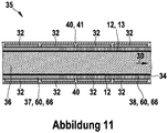
- FIG 11 shows a fourth embodiment 35 of the device according to the invention, which is apparent from the third embodiment 33 in that the internal electrodes 7, 8, 9 and 10 of the embedded first embodiment 1 omitted.
- a gas phase 36 vapor phase
- a heat pipe 34 heat pipe
- Non-mixing liquid phases 37 and 38 of the heat exchange medium 66 flow as in the third embodiment 33 through the outer flow channel 60 opposite to the flow direction 30 of the gas phase 36.
- FIG 12 shows a fifth embodiment 39 of the device according to the invention, wherein the inner electrode 11 as in the first embodiment 1 and the outer electrodes 32 and the outer walls 40 and 41 as in the second embodiment 31 are made in several parts and separated.
- the electrodes 11 and 32 are aligned flush at their ends in the flow direction 30 and may be designed in sections as a closed tube or plate-shaped.
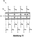
- each of the electrodes 11 and 32 is electrically connected to exactly one independently controllable voltage source U A1 -U A4 , U B1 -U B4 , U E1 -U E4 of the voltage control device 17 or exactly one independently controllable charge source of the charge control device 20.
- Figure 13 shows a sixth embodiment 43 of the device according to the invention, which is apparent from the fifth embodiment 39 in that the ends of the outer electrodes 32 and inner electrodes 11 are arranged offset in the flow direction 30.
- Figure 14 shows a seventh embodiment 44 of the device according to the invention, which is apparent from the sixth embodiment 43 in that the internal electrodes 11 omitted together with the connected voltage control device 17 or charge control device 20.
- Figure 15 shows an eighth embodiment 47 of the device according to the invention, which emerges from the seventh embodiment 44 in that the ends of the outer wall 40 embedded in the outer electrodes 32 opposite to the ends of the embedded outer wall in the outer wall 41 outer electrodes 32 are arranged offset in the flow direction 30 against each other.
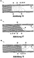
- Figures 16 to 19 show a second implementation of the method according to the invention in the eighth embodiment 44 of the device with an electrode-spanning and advancing in the direction 27 advancing field excitation 19 "by three electrodes 32.
- the electric field lines deform the dielectric boundary layer 16 obliquely to the feed direction 27. Die Representation gives the field lines only qualitatively correct, surface tensions and capillary forces are disregarded.
- Figures 20 to 23 show a third implementation of the method according to the invention in the eighth embodiment 44 of the device with progressive field excitation 19 "by means of a pair transverse to the feed direction 27 of oppositely disposed electrodes 32.
- the electric field lines distort the dielectric interface 16 qualitatively similar shown in Figures 16 to 19.
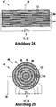
- FIGS. 24 and 25 show a ninth embodiment 47 and a tenth embodiment 48 of the device according to the invention, each in cross section, the paper plane of the illustration being orthogonal to the flow direction 30 or feed direction 27.
- a high capacitance covering and thus a high feed force 27 ' are achieved in that the thin internal electrodes 49 are arranged in a layered or wound manner.
- an electrolytic carrier film as used in electrolytic capacitors or a plastic dielectric, which occurs in film capacitors, a permeable in the feed direction 27 support film 50 is provided.
- Figure 24 shows a layer arrangement of plate-shaped, individual electrodes 49, which are enclosed by a closed, electrically conductive flow wall 12 of rectangular cross section, which is at ground potential 18.
- the electrodes 49 and the flow wall 12 are arranged separately from each other. Furthermore, the electrical connection of the internal electrodes 49 with an electric voltage source of the voltage control device 17 or a charge source of the charge control device 20 is provided.
- Figure 25 shows a radial layer arrangement of circular, individual electrodes 49, which are enclosed by a closed, electrically conductive flow wall 12 of rectangular cross-section, which is at ground potential 18.
- the electrodes 49 and the flow wall 12 are arranged separately from each other. Furthermore, the electrical connection of the internal electrodes 49 with an electric voltage source of the voltage control device 17 or a charge source of the charge control device 20 is provided.
Landscapes
- Engineering & Computer Science (AREA)
- Mechanical Engineering (AREA)
- General Engineering & Computer Science (AREA)
- Physics & Mathematics (AREA)
- Thermal Sciences (AREA)
- Physical Or Chemical Processes And Apparatus (AREA)
- Structures Of Non-Positive Displacement Pumps (AREA)
Claims (16)
- Procédé de transport d'au moins un milieu d'échange de chaleur (2, 66), lequel possède au moins un premier fluide (3, 4, 5) qui présente une première permittivité et au moins un deuxième fluide (3, 4, 5) qui ne se mélange pas avec le premier fluide (3, 4, 5), lequel présente une deuxième permittivité qui est différente de la première permittivité, au moins une surface de délimitation (16) diélectrique étant formée entre le premier et le deuxième fluide (3, 4, 5), laquelle est exposée à un champ d'avancement (19) électrique excité progressivement, lequel exerce une force d'avancement (27') sur l'au moins une surface de délimitation (16) diélectrique, et le champ d'avancement (19) électrique étant progressivement excité par un arrangement d'électrodes (14) qui se compose d'au moins deux électrodes (7, 8, 9, 10, 11, 12, 13, 32, 49) voisines, notamment dans le sens de l'avancement (27), un dispositif de commande de tension (17) avec des sources de tension commandées indépendamment ou un dispositif de commande de charge (20) avec des sources de charge commandées indépendamment étant associé à chaque électrode (7, 8, 9, 10, 11, 12, 13, 32, 49) de l'arrangement d'électrodes (14).
- Procédé selon la revendication 1, caractérisé en ce que le premier fluide (3, 4, 5) utilisé est un premier liquide et le deuxième fluide (3, 4, 5) utilisé est un deuxième liquide dont la permittivité est différente de la permittivité du premier liquide.
- Procédé selon l'une des revendications précédentes, caractérisé en ce que le premier fluide (3, 4, 5) utilisé est un liquide et le deuxième fluide (3, 4, 5) utilisé est un gaz, notamment en ce que le gaz est la phase gazeuse (36) du premier fluide (3, 4, 5) .
- Procédé selon l'une des revendications précédentes, caractérisé en ce que les forces d'avancement (27') sur le milieu d'échange de chaleur (2, 66) à transporter sont générées avec un champ électrique (19'), lequel est notamment excité avec un arrangement d'électrodes (14) dans les zones des surfaces de délimitation (16) diélectriques entre les fluides (3, 4, 5) de permittivité différente.
- Procédé selon l'une des revendications précédentes, caractérisé en ce que le milieu d'échange de chaleur (2, 66) est maintenu en cohésion ou maintenu concentré au moyen d'un champ électrique statique qui est superposé au champ d'avancement (19) électrique excité progressivement.
- Procédé selon l'une des revendications précédentes, caractérisé en ce que le champ d'avancement (19) électrique est excité progressivement par déplacement de la charge électrique sur d'autres électrodes (7, 8, 9, 10, 11, 12, 13, 32, 49) de l'arrangement d'électrodes (14) dans le sens de l'avancement (27).
- Procédé selon l'une des revendications précédentes, caractérisé en ce que la position d'au moins une surface de délimitation (16) diélectrique dans le milieu d'échange de chaleur (2, 66) est déterminée au moyen de la mesure de la capacité de l'arrangement d'électrodes (14) d'excitation du champ et la vitesse d'écoulement d'au moins une portion de fluide (3', 4', 5') est déterminée à partir de la variation dans le temps de la position d'au moins une surface de délimitation (16) diélectrique.
- Procédé selon l'une des revendications précédentes, caractérisé en ce que la température d'au moins une portion de fluide (3', 4', 5') contenue dans le milieu d'échange de chaleur (2, 66) est déterminée au moyen de la capacité mesurée et d'au moins un paramètre supplémentaire, notamment de la dépendance à la température de la permittivité du fluide (3, 4, 5).
- Procédé selon l'une des revendications précédentes, caractérisé en ce qu'un flux thermique est déterminé au moyen de la température, de la vitesse d'écoulement et de la capacité calorifique spécifique d'au moins une portion de fluide (3', 4', 5') contenue dans le milieu d'échange de chaleur (2, 66).
- Dispositif pour transporter au moins un milieu d'échange de chaleur (2, 66), lequel possède au moins un premier fluide (3, 4, 5) qui présente une première permittivité et au moins un deuxième fluide (3, 4, 5) qui ne se mélange pas avec le premier fluide (3, 4, 5), lequel présente une deuxième permittivité qui est différente de la première permittivité, au moins une surface de délimitation (16) diélectrique étant formée entre le premier et le deuxième fluide (3, 4, 5), caractérisé par un arrangement d'électrodes (14) capacitif qui se compose, notamment dans le sens d'avancement (27), d'au moins deux électrodes (7, 8, 9, 10, 11, 12, 13, 32, 49) voisines, un dispositif de commande de tension (17) avec des sources de tension commandées indépendamment ou un dispositif de commande de charge (20) avec des sources de charge commandées indépendamment étant associé à chaque électrode (7, 8, 9, 10, 11, 12, 13, 32, 49) de l'arrangement d'électrodes (14'), le dispositif de commande de tension (17) étant configuré pour faire varier les tensions électriques appliquées aux électrodes (7, 8, 9, 10, 11, 12, 13, 32, 49) de l'arrangement d'électrodes (14) de telle sorte qu'un champ d'avancement (19) électrique est excité progressivement par l'arrangement d'électrodes (14) de telle sorte que l'au moins une surface de délimitation (16) diélectrique est exposée au champ d'avancement (19) électrique excité progressivement de telle sorte que le champ d'avancement (19) exerce une force d'avancement (27') sur l'au moins une surface de délimitation (16) diélectrique, la force d'avancement (27') agissant dans la direction de la capacité croissante de l'arrangement d'électrodes (14) qui excite le champ d'avancement (19) .
- Dispositif selon la revendication 10, caractérisé en ce que le transport du milieu d'échange de chaleur (2, 66) s'effectue dans un canal d'écoulement (6, 60) qui s'étend dans les espaces intermédiaires de l'arrangement d'électrodes (14) associé.
- Dispositif selon l'une des revendications précédentes 10 à 11, caractérisé en ce que les électrodes extérieures (12, 13, 32) sont réalisées sous la forme de la paroi extérieure fermée (12', 13', 40, 41) du canal d'écoulement (6, 60).
- Dispositif selon la revendication 12, caractérisé en ce que les autres électrodes (7, 8, 9, 10, 11, 49) sont entièrement entourées par les électrodes extérieures (12, 13, 32), les électrodes extérieures (12, 13, 32) et les autres électrodes (7, 8, 9, 10, 11, 49) étant séparées les unes des autres.
- Dispositif selon l'une des revendications précédentes 10 à 11, caractérisé en ce qu'au moins deux des électrodes (7, 8, 9, 10) sont réalisées sous la forme d'électrodes extérieures (12, 13, 32) séparées les unes des autres, les électrodes extérieures (12, 13, 32) étant isolées électriquement les unes des autres et étant enrobées dans une paroi extérieure (40, 41) électriquement isolée ou fixées sur le côté intérieur de la paroi extérieure (40, 41).
- Dispositif selon la revendication 14, caractérisé en ce qu'une autre électrode intérieure (7, 8, 9, 10, 11, 49) est disposée à l'intérieur du canal d'écoulement (6, 60).
- Dispositif selon l'une des revendications précédentes 10 à 15, caractérisé en ce que l'arrangement d'électrodes (14) possède un dispositif servant à mesurer au moins une capacité.
Applications Claiming Priority (2)
| Application Number | Priority Date | Filing Date | Title |
|---|---|---|---|
| DE102008040225A DE102008040225A1 (de) | 2008-07-07 | 2008-07-07 | Kapazitive Vorrichtung und Verfahren zum elektrostatischen Transport dielektrischer und ferroelektrischer Fluide |
| PCT/EP2009/057159 WO2010003752A1 (fr) | 2008-07-07 | 2009-06-10 | Dispositif capacitif et procédé de transport électrostatique de fluides diélectriques et ferroélectriques |
Publications (2)
| Publication Number | Publication Date |
|---|---|
| EP2297540A1 EP2297540A1 (fr) | 2011-03-23 |
| EP2297540B1 true EP2297540B1 (fr) | 2018-02-14 |
Family
ID=41055325
Family Applications (1)
| Application Number | Title | Priority Date | Filing Date |
|---|---|---|---|
| EP09779702.1A Active EP2297540B1 (fr) | 2008-07-07 | 2009-06-10 | Dispositif capacitif et procédé de transport électrostatique de fluides diélectriques et ferroélectriques |
Country Status (8)
| Country | Link |
|---|---|
| US (1) | US8764410B2 (fr) |
| EP (1) | EP2297540B1 (fr) |
| JP (1) | JP5274658B2 (fr) |
| KR (1) | KR101579762B1 (fr) |
| CN (1) | CN102089613B (fr) |
| BR (1) | BRPI0912104B1 (fr) |
| DE (1) | DE102008040225A1 (fr) |
| WO (1) | WO2010003752A1 (fr) |
Families Citing this family (7)
| Publication number | Priority date | Publication date | Assignee | Title |
|---|---|---|---|---|
| US9027342B2 (en) | 2011-04-21 | 2015-05-12 | Nicholas Frederick Foy | Supplementary intercooler for internal combustion engines |
| US10537830B2 (en) * | 2018-02-05 | 2020-01-21 | Saudi Arabian Oil Company | Method and apparatus for promoting droplets coalescence in oil continuous emulsions |
| DE102018204852A1 (de) * | 2018-03-29 | 2019-10-02 | Robert Bosch Gmbh | Schmiereinheit, Führung und Verfahren für eine Führung |
| US11041576B2 (en) * | 2018-10-25 | 2021-06-22 | Toyota Motor Engineering & Manufacturing North America, Inc. | Actuator with static activated position |
| CN109307444B (zh) * | 2018-11-16 | 2024-04-02 | 上海海事大学 | 一种免维护多级组合电射流泵 |
| CN114812874B (zh) * | 2022-05-10 | 2022-11-29 | 广州航海学院 | 微纳力源装置、控制方法、微纳力测量设备及存储介质 |
| US12577945B2 (en) * | 2023-05-23 | 2026-03-17 | Blue Origin Manufacturing, LLC | Pump for two-phase magnetic fluids |
Family Cites Families (19)
| Publication number | Priority date | Publication date | Assignee | Title |
|---|---|---|---|---|
| US2691303A (en) * | 1950-06-19 | 1954-10-12 | Phillips Petroleum Co | Magnetic type flowmeter |
| DE1601184C3 (de) | 1967-12-23 | 1974-07-04 | Deutsche Forschungs- U. Versuchsanstalt Fuer Luft- Und Raumfahrt E.V., 5050 Porz-Wahn | Zwischenwärmeträger-Umlaufsystem |
| US3906415A (en) * | 1974-06-14 | 1975-09-16 | Massachusetts Inst Technology | Apparatus wherein a segmented fluid stream performs electrical switching functions and the like |
| US4220195A (en) * | 1979-05-24 | 1980-09-02 | The United States Of America As Represented By The Secretary Of The Navy | Ion drag pumped heat pipe |
| US4396055A (en) * | 1981-01-19 | 1983-08-02 | The United States Of America As Represented By The Secretary Of The Navy | Electrohydrodynamic inductively pumped heat pipe |
| US4774453A (en) * | 1984-10-09 | 1988-09-27 | Auburn International, Inc. | Measuring flow of insulating fluids |
| DE4012268A1 (de) * | 1990-04-17 | 1991-10-24 | Joerg Fricke | Pumpe zur foerderung elektroviskoser fluessigkeiten |
| US6409975B1 (en) * | 1999-05-21 | 2002-06-25 | The Texas A&M University System | Electrohydrodynamic induction pumping thermal energy transfer system and method |
| AU2001280627A1 (en) * | 2000-07-18 | 2002-01-30 | Illinois Institute Of Technology | Electrohydrodynamic conduction pump |
| US6443704B1 (en) | 2001-03-02 | 2002-09-03 | Jafar Darabi | Electrohydrodynamicly enhanced micro cooling system for integrated circuits |
| US6856037B2 (en) | 2001-11-26 | 2005-02-15 | Sony Corporation | Method and apparatus for converting dissipated heat to work energy |
| US7004238B2 (en) * | 2001-12-18 | 2006-02-28 | Illinois Institute Of Technology | Electrode design for electrohydrodynamic induction pumping thermal energy transfer system |
| WO2004001944A1 (fr) * | 2002-06-21 | 2003-12-31 | Illinois Institute Of Technology | Structure d'electrode utile pour le pompage par conduction electrohydrodynamique |
| WO2006079111A2 (fr) * | 2005-01-24 | 2006-07-27 | Thorrn Micro Technologies, Inc. | Systeme de refroidissement a flux de gaz electro-hydrodynamique |
| US7133786B1 (en) | 2005-06-08 | 2006-11-07 | Roxar Flow Management As | Method and apparatus for measuring nonhomogeneous flow phase velocities |
| US7503227B2 (en) | 2005-07-13 | 2009-03-17 | Cidra Corporate Services, Inc | Method and apparatus for measuring parameters of a fluid flow using an array of sensors |
| DE102005039290A1 (de) * | 2005-08-19 | 2007-02-22 | Robert Bosch Gmbh | Vorrichtung zur triboelektrischen Massenstrommessung in fluiden Medien |
| WO2007072914A1 (fr) * | 2005-12-21 | 2007-06-28 | Kyocera Corporation | Pompe à écoulement électro-osmotique, système de pompage, puce microchimique et pile à combustible |
| DE102007018752B4 (de) | 2007-04-20 | 2011-09-22 | Fraunhofer-Gesellschaft zur Förderung der angewandten Forschung e.V. | Vorrichtung und Verfahren zum geregelten Transport mikrofluidischer Proben |
-
2008
- 2008-07-07 DE DE102008040225A patent/DE102008040225A1/de not_active Withdrawn
-
2009
- 2009-06-10 BR BRPI0912104-8A patent/BRPI0912104B1/pt active IP Right Grant
- 2009-06-10 EP EP09779702.1A patent/EP2297540B1/fr active Active
- 2009-06-10 JP JP2011517054A patent/JP5274658B2/ja active Active
- 2009-06-10 WO PCT/EP2009/057159 patent/WO2010003752A1/fr not_active Ceased
- 2009-06-10 CN CN200980126651.2A patent/CN102089613B/zh active Active
- 2009-06-10 KR KR1020117000447A patent/KR101579762B1/ko active Active
- 2009-06-10 US US12/737,379 patent/US8764410B2/en active Active
Also Published As
| Publication number | Publication date |
|---|---|
| KR101579762B1 (ko) | 2015-12-23 |
| WO2010003752A1 (fr) | 2010-01-14 |
| CN102089613B (zh) | 2014-03-05 |
| JP2011527175A (ja) | 2011-10-20 |
| US20110220330A1 (en) | 2011-09-15 |
| BRPI0912104A2 (pt) | 2015-10-13 |
| KR20110038025A (ko) | 2011-04-13 |
| EP2297540A1 (fr) | 2011-03-23 |
| BRPI0912104B1 (pt) | 2019-09-10 |
| US8764410B2 (en) | 2014-07-01 |
| JP5274658B2 (ja) | 2013-08-28 |
| DE102008040225A1 (de) | 2010-01-14 |
| CN102089613A (zh) | 2011-06-08 |
Similar Documents
| Publication | Publication Date | Title |
|---|---|---|
| WO2010003752A1 (fr) | Dispositif capacitif et procédé de transport électrostatique de fluides diélectriques et ferroélectriques | |
| EP2361441B1 (fr) | Module pour générateur thermoélectrique et générateur thermoélectrique | |
| WO2013050450A1 (fr) | Dispositif de transfert thermique, plaque de thermorégulation et dispositif d'accumulation d'énergie | |
| EP2917555B1 (fr) | Dispositif de préchauffage destiné à un système d'injection de carburant | |
| WO2012101145A1 (fr) | Module thermoélectrique muni d'une couche thermoconductrice | |
| DE10315039B4 (de) | Gassensor mit einem mehrschichtigen Gaserfassungselement | |
| DE102018215398A1 (de) | Elektrische Heizeinrichtung | |
| EP2212688B1 (fr) | Procédé pour déterminer la teneur en carburant d'une huile moteur d'un véhicule automobile | |
| DE102013112911A1 (de) | Thermoelektrische Generatorvorrichtung und Verfahren zur Herstellung einer thermoelektrischen Generatorvorrichtung | |
| EP2002252A1 (fr) | Élement de detection pour determiner une proportion de gaz avec proprietes thermiques ameliorees | |
| AT518304A1 (de) | Vorrichtung zum Temperieren einer Messprobe | |
| DE102007044634B4 (de) | Hochtemperatur-Polymer-Elektrolyt-Membran-Brennstoffzelle (HT-PEMFC) einschließlich Vorrichtungen zu deren Kühlung | |
| DE102006022772A1 (de) | Antriebsanordnung für eine Vakuumpumpe | |
| EP1642335A1 (fr) | Ensemble circuit integre a refroidissement et procede de fabrication dudit ensemble | |
| DE102018117059B4 (de) | Batteriemodul für eine Traktionsbatterie eines elektrisch antreibbaren Kraftfahrzeugs | |
| DE102019005453A1 (de) | Verfahren zur Ermittlung eines Wärmeübergangs | |
| DE102010013467A1 (de) | Temperierelement und Temperiervorrichtung für ein Fahrzeug | |
| EP3821190A1 (fr) | Échangeur de chaleur et procédé de fabrication d'un échangeur de chaleur | |
| DE29515932U1 (de) | Durchlauferwärmungsvorrichtung | |
| EP3714138B1 (fr) | Dispositif de chauffage et son procédé de fabrication | |
| AT524204A4 (de) | Temperiervorrichtung für ein gasförmiges Medium | |
| EP3651123A1 (fr) | Procédé de détermination de la consommation pendant la durée de vie d'un appareil technique traversé par un fluide | |
| DE102012025632B3 (de) | Wärmetauscher, Abgasanlage und Brennkraftmaschine | |
| DE102016102893A1 (de) | Wärmetauschersystem | |
| DE2620052B2 (de) | Verfahren und Vorrichtung zum Feststellen eines knapp bevorstehenden Phasenwechsels |
Legal Events
| Date | Code | Title | Description |
|---|---|---|---|
| PUAI | Public reference made under article 153(3) epc to a published international application that has entered the european phase |
Free format text: ORIGINAL CODE: 0009012 |
|
| 17P | Request for examination filed |
Effective date: 20110207 |
|
| AK | Designated contracting states |
Kind code of ref document: A1 Designated state(s): AT BE BG CH CY CZ DE DK EE ES FI FR GB GR HR HU IE IS IT LI LT LU LV MC MK MT NL NO PL PT RO SE SI SK TR |
|
| AX | Request for extension of the european patent |
Extension state: AL BA RS |
|
| DAX | Request for extension of the european patent (deleted) | ||
| 17Q | First examination report despatched |
Effective date: 20151208 |
|
| REG | Reference to a national code |
Ref country code: DE Ref legal event code: R079 Ref document number: 502009014729 Country of ref document: DE Free format text: PREVIOUS MAIN CLASS: F28F0013160000 Ipc: F04B0019000000 |
|
| RIC1 | Information provided on ipc code assigned before grant |
Ipc: F28F 13/16 20060101ALI20170802BHEP Ipc: F28D 15/00 20060101ALI20170802BHEP Ipc: F04B 19/00 20060101AFI20170802BHEP |
|
| GRAP | Despatch of communication of intention to grant a patent |
Free format text: ORIGINAL CODE: EPIDOSNIGR1 |
|
| INTG | Intention to grant announced |
Effective date: 20170914 |
|
| GRAS | Grant fee paid |
Free format text: ORIGINAL CODE: EPIDOSNIGR3 |
|
| GRAA | (expected) grant |
Free format text: ORIGINAL CODE: 0009210 |
|
| AK | Designated contracting states |
Kind code of ref document: B1 Designated state(s): AT BE BG CH CY CZ DE DK EE ES FI FR GB GR HR HU IE IS IT LI LT LU LV MC MK MT NL NO PL PT RO SE SI SK TR |
|
| REG | Reference to a national code |
Ref country code: GB Ref legal event code: FG4D Free format text: NOT ENGLISH |
|
| REG | Reference to a national code |
Ref country code: CH Ref legal event code: EP |
|
| REG | Reference to a national code |
Ref country code: IE Ref legal event code: FG4D Free format text: LANGUAGE OF EP DOCUMENT: GERMAN |
|
| REG | Reference to a national code |
Ref country code: DE Ref legal event code: R096 Ref document number: 502009014729 Country of ref document: DE Ref country code: AT Ref legal event code: REF Ref document number: 970017 Country of ref document: AT Kind code of ref document: T Effective date: 20180315 |
|
| REG | Reference to a national code |
Ref country code: NL Ref legal event code: MP Effective date: 20180214 |
|
| REG | Reference to a national code |
Ref country code: FR Ref legal event code: PLFP Year of fee payment: 10 |
|
| PG25 | Lapsed in a contracting state [announced via postgrant information from national office to epo] |
Ref country code: HR Free format text: LAPSE BECAUSE OF FAILURE TO SUBMIT A TRANSLATION OF THE DESCRIPTION OR TO PAY THE FEE WITHIN THE PRESCRIBED TIME-LIMIT Effective date: 20180214 Ref country code: CY Free format text: LAPSE BECAUSE OF FAILURE TO SUBMIT A TRANSLATION OF THE DESCRIPTION OR TO PAY THE FEE WITHIN THE PRESCRIBED TIME-LIMIT Effective date: 20180214 Ref country code: LT Free format text: LAPSE BECAUSE OF FAILURE TO SUBMIT A TRANSLATION OF THE DESCRIPTION OR TO PAY THE FEE WITHIN THE PRESCRIBED TIME-LIMIT Effective date: 20180214 Ref country code: FI Free format text: LAPSE BECAUSE OF FAILURE TO SUBMIT A TRANSLATION OF THE DESCRIPTION OR TO PAY THE FEE WITHIN THE PRESCRIBED TIME-LIMIT Effective date: 20180214 Ref country code: NO Free format text: LAPSE BECAUSE OF FAILURE TO SUBMIT A TRANSLATION OF THE DESCRIPTION OR TO PAY THE FEE WITHIN THE PRESCRIBED TIME-LIMIT Effective date: 20180514 Ref country code: ES Free format text: LAPSE BECAUSE OF FAILURE TO SUBMIT A TRANSLATION OF THE DESCRIPTION OR TO PAY THE FEE WITHIN THE PRESCRIBED TIME-LIMIT Effective date: 20180214 Ref country code: NL Free format text: LAPSE BECAUSE OF FAILURE TO SUBMIT A TRANSLATION OF THE DESCRIPTION OR TO PAY THE FEE WITHIN THE PRESCRIBED TIME-LIMIT Effective date: 20180214 |
|
| PG25 | Lapsed in a contracting state [announced via postgrant information from national office to epo] |
Ref country code: GR Free format text: LAPSE BECAUSE OF FAILURE TO SUBMIT A TRANSLATION OF THE DESCRIPTION OR TO PAY THE FEE WITHIN THE PRESCRIBED TIME-LIMIT Effective date: 20180515 Ref country code: LV Free format text: LAPSE BECAUSE OF FAILURE TO SUBMIT A TRANSLATION OF THE DESCRIPTION OR TO PAY THE FEE WITHIN THE PRESCRIBED TIME-LIMIT Effective date: 20180214 Ref country code: SE Free format text: LAPSE BECAUSE OF FAILURE TO SUBMIT A TRANSLATION OF THE DESCRIPTION OR TO PAY THE FEE WITHIN THE PRESCRIBED TIME-LIMIT Effective date: 20180214 Ref country code: BG Free format text: LAPSE BECAUSE OF FAILURE TO SUBMIT A TRANSLATION OF THE DESCRIPTION OR TO PAY THE FEE WITHIN THE PRESCRIBED TIME-LIMIT Effective date: 20180514 |
|
| PG25 | Lapsed in a contracting state [announced via postgrant information from national office to epo] |
Ref country code: MT Free format text: LAPSE BECAUSE OF FAILURE TO SUBMIT A TRANSLATION OF THE DESCRIPTION OR TO PAY THE FEE WITHIN THE PRESCRIBED TIME-LIMIT Effective date: 20180214 |
|
| PG25 | Lapsed in a contracting state [announced via postgrant information from national office to epo] |
Ref country code: EE Free format text: LAPSE BECAUSE OF FAILURE TO SUBMIT A TRANSLATION OF THE DESCRIPTION OR TO PAY THE FEE WITHIN THE PRESCRIBED TIME-LIMIT Effective date: 20180214 Ref country code: RO Free format text: LAPSE BECAUSE OF FAILURE TO SUBMIT A TRANSLATION OF THE DESCRIPTION OR TO PAY THE FEE WITHIN THE PRESCRIBED TIME-LIMIT Effective date: 20180214 Ref country code: PL Free format text: LAPSE BECAUSE OF FAILURE TO SUBMIT A TRANSLATION OF THE DESCRIPTION OR TO PAY THE FEE WITHIN THE PRESCRIBED TIME-LIMIT Effective date: 20180214 |
|
| REG | Reference to a national code |
Ref country code: DE Ref legal event code: R097 Ref document number: 502009014729 Country of ref document: DE |
|
| PG25 | Lapsed in a contracting state [announced via postgrant information from national office to epo] |
Ref country code: SK Free format text: LAPSE BECAUSE OF FAILURE TO SUBMIT A TRANSLATION OF THE DESCRIPTION OR TO PAY THE FEE WITHIN THE PRESCRIBED TIME-LIMIT Effective date: 20180214 Ref country code: CZ Free format text: LAPSE BECAUSE OF FAILURE TO SUBMIT A TRANSLATION OF THE DESCRIPTION OR TO PAY THE FEE WITHIN THE PRESCRIBED TIME-LIMIT Effective date: 20180214 Ref country code: DK Free format text: LAPSE BECAUSE OF FAILURE TO SUBMIT A TRANSLATION OF THE DESCRIPTION OR TO PAY THE FEE WITHIN THE PRESCRIBED TIME-LIMIT Effective date: 20180214 |
|
| PLBE | No opposition filed within time limit |
Free format text: ORIGINAL CODE: 0009261 |
|
| STAA | Information on the status of an ep patent application or granted ep patent |
Free format text: STATUS: NO OPPOSITION FILED WITHIN TIME LIMIT |
|
| 26N | No opposition filed |
Effective date: 20181115 |
|
| REG | Reference to a national code |
Ref country code: CH Ref legal event code: PL |
|
| GBPC | Gb: european patent ceased through non-payment of renewal fee |
Effective date: 20180610 |
|
| PG25 | Lapsed in a contracting state [announced via postgrant information from national office to epo] |
Ref country code: SI Free format text: LAPSE BECAUSE OF FAILURE TO SUBMIT A TRANSLATION OF THE DESCRIPTION OR TO PAY THE FEE WITHIN THE PRESCRIBED TIME-LIMIT Effective date: 20180214 |
|
| REG | Reference to a national code |
Ref country code: BE Ref legal event code: MM Effective date: 20180630 |
|
| REG | Reference to a national code |
Ref country code: IE Ref legal event code: MM4A |
|
| PG25 | Lapsed in a contracting state [announced via postgrant information from national office to epo] |
Ref country code: MC Free format text: LAPSE BECAUSE OF FAILURE TO SUBMIT A TRANSLATION OF THE DESCRIPTION OR TO PAY THE FEE WITHIN THE PRESCRIBED TIME-LIMIT Effective date: 20180214 Ref country code: LU Free format text: LAPSE BECAUSE OF NON-PAYMENT OF DUE FEES Effective date: 20180610 |
|
| PG25 | Lapsed in a contracting state [announced via postgrant information from national office to epo] |
Ref country code: CH Free format text: LAPSE BECAUSE OF NON-PAYMENT OF DUE FEES Effective date: 20180630 Ref country code: LI Free format text: LAPSE BECAUSE OF NON-PAYMENT OF DUE FEES Effective date: 20180630 Ref country code: GB Free format text: LAPSE BECAUSE OF NON-PAYMENT OF DUE FEES Effective date: 20180610 Ref country code: IE Free format text: LAPSE BECAUSE OF NON-PAYMENT OF DUE FEES Effective date: 20180610 |
|
| PG25 | Lapsed in a contracting state [announced via postgrant information from national office to epo] |
Ref country code: BE Free format text: LAPSE BECAUSE OF NON-PAYMENT OF DUE FEES Effective date: 20180630 |
|
| REG | Reference to a national code |
Ref country code: AT Ref legal event code: MM01 Ref document number: 970017 Country of ref document: AT Kind code of ref document: T Effective date: 20180610 |
|
| PG25 | Lapsed in a contracting state [announced via postgrant information from national office to epo] |
Ref country code: AT Free format text: LAPSE BECAUSE OF NON-PAYMENT OF DUE FEES Effective date: 20180610 |
|
| PG25 | Lapsed in a contracting state [announced via postgrant information from national office to epo] |
Ref country code: TR Free format text: LAPSE BECAUSE OF FAILURE TO SUBMIT A TRANSLATION OF THE DESCRIPTION OR TO PAY THE FEE WITHIN THE PRESCRIBED TIME-LIMIT Effective date: 20180214 |
|
| PG25 | Lapsed in a contracting state [announced via postgrant information from national office to epo] |
Ref country code: HU Free format text: LAPSE BECAUSE OF FAILURE TO SUBMIT A TRANSLATION OF THE DESCRIPTION OR TO PAY THE FEE WITHIN THE PRESCRIBED TIME-LIMIT; INVALID AB INITIO Effective date: 20090610 Ref country code: PT Free format text: LAPSE BECAUSE OF FAILURE TO SUBMIT A TRANSLATION OF THE DESCRIPTION OR TO PAY THE FEE WITHIN THE PRESCRIBED TIME-LIMIT Effective date: 20180214 |
|
| PG25 | Lapsed in a contracting state [announced via postgrant information from national office to epo] |
Ref country code: MK Free format text: LAPSE BECAUSE OF NON-PAYMENT OF DUE FEES Effective date: 20180214 |
|
| PG25 | Lapsed in a contracting state [announced via postgrant information from national office to epo] |
Ref country code: IS Free format text: LAPSE BECAUSE OF FAILURE TO SUBMIT A TRANSLATION OF THE DESCRIPTION OR TO PAY THE FEE WITHIN THE PRESCRIBED TIME-LIMIT Effective date: 20180614 |
|
| P01 | Opt-out of the competence of the unified patent court (upc) registered |
Effective date: 20230509 |
|
| PGFP | Annual fee paid to national office [announced via postgrant information from national office to epo] |
Ref country code: DE Payment date: 20250814 Year of fee payment: 17 |
|
| PGFP | Annual fee paid to national office [announced via postgrant information from national office to epo] |
Ref country code: IT Payment date: 20250630 Year of fee payment: 17 |
|
| PGFP | Annual fee paid to national office [announced via postgrant information from national office to epo] |
Ref country code: FR Payment date: 20260622 Year of fee payment: 18 |