EP2297563B1 - Balancing device, balancing system, and balancing method - Google Patents
Balancing device, balancing system, and balancing method Download PDFInfo
- Publication number
- EP2297563B1 EP2297563B1 EP09768943.4A EP09768943A EP2297563B1 EP 2297563 B1 EP2297563 B1 EP 2297563B1 EP 09768943 A EP09768943 A EP 09768943A EP 2297563 B1 EP2297563 B1 EP 2297563B1
- Authority
- EP
- European Patent Office
- Prior art keywords
- balancing
- unit
- mass
- accordance
- rotational position
- Prior art date
- Legal status (The legal status is an assumption and is not a legal conclusion. Google has not performed a legal analysis and makes no representation as to the accuracy of the status listed.)
- Active
Links
Images

Classifications
-
- G—PHYSICS
- G01—MEASURING; TESTING
- G01M—TESTING STATIC OR DYNAMIC BALANCE OF MACHINES OR STRUCTURES; TESTING OF STRUCTURES OR APPARATUS, NOT OTHERWISE PROVIDED FOR
- G01M1/00—Testing static or dynamic balance of machines or structures
- G01M1/30—Compensating imbalance
- G01M1/36—Compensating imbalance by adjusting position of masses built-in the body to be tested
Definitions
- the invention relates to a balancing device, in particular a balancing head or a balancing ring, for an electromechanical balancing system for rotating units, in particular for spindles of machine tools, with at least one balancing mass, which is adjustable to compensate for an imbalance of the unit, and a drive unit, in particular an electric motor. for adjusting the balancing mass.
- balancing devices are in the documents EP1580543 . WO01 / 98745 and US2006 / 0005623 disclosed.
- balancing heads which have adjustable weights.
- the weights are adjusted, and the behavior of the overall system during this adjustment process is observed with regard to the magnitude and the phase or angular position of the balance compensating the respective imbalance resulting from the weights.
- a disadvantage of these systems is in particular the long time required for the balancing process.
- the object of the invention is to provide a way of balancing rotating units, which guarantees high reliability, requires as little time as possible and is automatically feasible.
- the invention makes it possible to calculate a desired position for the balancing mass from the measured imbalance and then to move the balancing mass directly into this desired position.
- the setpoint position is characterized by the fact that the balancing mass located in the setpoint position just compensates the measured imbalance.
- the advantage of the balancing device according to the invention is, in particular, that it allows a fast and targeted automatic balancing due to the targeted positioning of the balancing mass.
- an electromechanical balancing system for rotating units in particular for spindles of machine tools, with at least one integrated in a rotating unit, attached to a rotating unit and / or mounted around a rotating unit around balancing device of the type specified here, and with a measuring device for determining an imbalance of the rotating unit.
- the object is achieved by a method according to claim 14 for, in particular automatic, balancing of rotating units by means of at least one balancing device of the type specified here, in which an imbalance of the unit is measured from the measured imbalance, a desired position for the balancing mass is calculated in which the balancing mass compensates the imbalance, and the balancing mass is adjusted to the desired position.
- the balancing device can be integrated into the rotating unit, can be mounted on the rotating unit and / or mounted around the rotating unit.
- Integratable and / or attachable balancing devices are also referred to as balancing heads.
- the invention can be implemented in conjunction with any desired designed electromechanical balancing devices.
- a further improvement of the balancing device is achieved in that, according to the invention, the absolute position of the balancing mass in each case is predetermined or determinable by the positions in a fixed coordinate system with respect to the balancing device.
- the absolute position of the balancing mass in each case is predetermined or determinable by the positions in a fixed coordinate system with respect to the balancing device.
- the positioning device comprises a device for measuring rotational positions.
- fundamentally known rotary position measuring devices can be used in an advantageous manner in order to ensure the positionability of the balancing mass.
- a permanent magnet is rotatably arranged relative to a suitably formed sensor, wherein the sensor is capable of measuring the rotational position of the permanent magnet with a resolution of well below 1 °.
- the positions are coded and readable by means of a code reader.
- One possibility for position coding according to a further embodiment of the invention is to encode the positions according to the Gray code principle.
- Graycodes and the associated advantages in particular in the transmission of information are basically known, which is why it need not be discussed in detail.
- Particularly advantageous with regard to the use for the positioning of balancing masses is the particular robustness or error-susceptibility of the information transmission.
- the coding of the positions according to the invention can be carried out according to the single-track Graycode principle.
- a circumferentially magnetized ring strip can serve as the code carrier, wherein a correspondingly formed ring strip serves as the code reader, which has a plurality of circumferentially distributed, responsive to the type of magnetization sensors, for example in the form of Hall probes are provided.
- an adjustment movement of the balancing mass is associated with a movement of a code carrier relative to a code reader, this movement resulting in a change of the readable position code.
- the code carrier and the balancing mass For example, they may be mechanically positively coupled, so that only a joint movement of balancing mass and code carrier is possible.
- the code carrier comprises at least one, in particular exactly one, annular code track.
- each balancing mass may be associated with an example annular code track.
- the balancing device may comprise a plurality of balancing masses, wherein in particular exactly two balancing masses are provided.
- the balancing masses are independently adjustable. If at least two balancing masses are provided, according to the invention the required balancing vector can be adjusted very quickly both in terms of magnitude and phase or direction.
- the individual balancing masses of the balancing device can be arranged offset from one another in the axial direction. Alternatively, an arrangement of the balancing masses with the same axial position is possible, which has the advantage that no axially spaced balancing planes exist and consequently no moment unbalance arises.
- the balancing device according to the invention is suitable for carrying out a multi-level balancing, wherein the balancing device has at least two arrangements of at least one balancing mass arranged at locations spaced from each other along an axis of the balancing device.
- a multi-level balancing which is often required in practice, has hitherto been difficult to handle, due to the unavoidable feedback between the two balancing points, ie a change in the balancing vector made at the one balancing point has a change in the ratios at the balancing point another balancing point result, and vice versa.
- a process device is integrated into the balancing device, which is designed at least to carry out at least part of the balancing process involving the balancing device as a function of a measured imbalance-related signals and / or data.
- the balancing device is in a position to carry out at least part of the required balancing process with regard to the processes required for this purpose.
- the process device is in particular additionally designed to acquire, process and / or store data and / or signals and / or execute processes which do not relate to the balancing process.
- an infrastructure that is required anyway for the balancing process can be used for other purposes.
- an external control device for controlling a balancing process of the balancing device and / or for communication with a process device integrated in the balancing device.
- This external control device can also be used to power the Balancing device and / or serve for communication with a higher-level machine control.
- a non-contact transmission device for supplying power to the balancing device and / or for communication between an external control device and a processing device integrated in the balancing device.
- a contactless transmission is known per se, so that need not be discussed further hereon.
- the balancing system may comprise a plurality of balancing means adapted to be arranged at locations spaced apart along the axis of rotation of the unit for performing multi-level balancing.
- important multi-level balancing may therefore be provided a plurality of balancing devices, and it is - as already mentioned - also possible to provide for this purpose a single balancing device comprising a plurality of balancing mass arrangements which are axially spaced.
- the balancing method provision is made in particular for the method, including the adjustment of the balancing mass, to be carried out while the unit is rotating.
- the balancing is carried out at rotating at operating or rated speed unit.
- the invention also relates to a rotating unit during operation, in particular a spindle of a machine tool, with at least one balancing device of the type specified here or with a balancing system of the type specified here.
- the invention relates to a machine tool with at least one balancing device of the type specified here or with a balancing system of the type specified here.
- Fig. 1 shows schematically in a plane perpendicular to the axis of rotation 45, a spindle 11 of a machine tool.
- the balancing system according to the invention can in principle be used in conjunction with any rotating units which it is necessary to balance.
- the unit to be balanced is referred to below as the spindle 11, in practice the overall system is generally relevant, which in addition to the spindle comprises the tool fastened to the spindle, for example a grinding wheel, the spindle bearing and one or more receiving flanges. So if in the following of the spindle 11 as a unit to be balanced is mentioned, then this is to be understood in each case relevant in practice, to be balanced overall arrangement.
- the spindle 11 is part of a machine tool, which is assigned to a higher-level machine control 29.
- the machine controller 29 communicates in the illustrated embodiment with an external control device 25, which is part of a balancing system according to the invention.
- the scope of the tasks that are taken over by the external control device 25 may vary within the scope of the invention. For example, it may be provided that required calculations are carried out by the external control device 25 for the positioning of the balancing masses, as will be explained in greater detail below. Nevertheless, it is possible that such calculations and other tasks are performed by a process device 21 which is integrated into the balancing device and rotates during operation.
- the control device 25 is an "external" component in that the control device 25 is not part of the rotating system, but is assigned to the stationary side.
- the balancing system according to the invention further comprises a balancing device, which is integrated into the spindle in the exemplary embodiment shown here and is also referred to below as a balancing head.
- a balancing device which is integrated into the spindle in the exemplary embodiment shown here and is also referred to below as a balancing head.
- the invention also includes balancing devices cooperating with the respective rotating unit in other ways, for example attachable balancing devices or balancing rings which enclose the respective rotating unit or a component thereof in the middle.
- Such balancing rings need not be in the form of a closed ring. In principle, it is possible to use such balancing devices in the form of ring segments, for example, have an approximately C-shaped structure to provide.
- a bidirectional communication with the balancing device integrated in the spindle 11 is possible. This opens up a variety of applications that have not yet been realized in connection with balancing devices.
- the balancing device integrated here into the spindle 11 comprises the already mentioned integrated process device 21 as well as two balancing masses 13, each movable on a circular path about the rotation axis 45, to each of which an electric motor 15 is assigned as a drive unit with a corresponding gear 47.
- the representation of the arrangement of these components in Fig. 1 is to be understood purely schematically.
- the balancing masses 13 may be spaced apart in the axial direction or have the same axial position at different radial positions.
- the balancing device comprises a positioning device 17, of which a code carrier 19 designed as a closed annular strip is shown here.
- the positioning device 17 will be described below in connection with Fig. 2 discussed in more detail.
- the code ring 19 shown here is assigned to one of the balancing masses 13 and can be rotated together with this balancing mass 13 about the axis of rotation 45.
- An adjusting movement of the balancing mass 13 by means of the associated electric motor 15 consequently results in a movement of the code ring 19, relative to a code reader 37 (cf. Fig. 2 ), resulting in a change of the readable position code.
- the other balancing mass 13 is also associated with a corresponding, not shown Codering, which is movable together with this balancing mass 13.
- the two balancing masses 13 and thus the two code rings 19 are movable independently of each other, i. the electric motors 15 are independently controllable, so that the two balancing masses 13 can be adjusted independently of each other in a respective predetermined position.
- the balancing system according to the invention further comprises a measuring device 23, for example a vibration sensor, which serves to determine an existing unbalance U.
- a measuring device 23 for example a vibration sensor, which serves to determine an existing unbalance U.
- the manner of embodiment of the measuring device 23 is basically arbitrary.
- the balancing system comprises a rotary signal generator which provides a value representing the rotational speed of the rotating spindle.
- Fig. 1 also shows a measuring device 35, for example a temperature sensor, which is not a mandatory component of the balancing system according to the invention.
- This sensor 35 illustrates a peculiarity of the balancing device according to the invention, which consists in that the integrated process device 21 not only performs tasks relating to the balancing process, but is additionally capable of performing balancing functions. This will be discussed in more detail below.
- the vibration sensor 23, the rotary signal transmitter 49 and the sensor 35 can, as indicated by dashed lines, communicate with the external control device 25, which provides the necessary data acquisition, signal processing and signal processing to at least the substantial part of the balancing process on the basis of this information Taxes.
- the mentioned components are connected directly to the processing device 21 integrated in the balancing device, so that a transmission of the information to the external control device 25 is not necessary.
- the integrated processing device 21 is provided with a detection and processing device, with which the incoming signals and / or data can be detected and processed.
- the integrated here in the spindle 11 balancing device is itself due to their integrated process device 21 in a position to procure the necessary as a basis for the control of the balancing process information or generate.
- the balancing device is an "intelligent" balancing device which does not receive only externally generated control signals for the electric motors 15 of the balancing masses 13.
- the process device 21 integrated in the balancing device in this exemplary embodiment is provided with a memory device 33 Mistake.
- the process device 21 can basically store any desired data, although this data may relate to the balancing process, but this is not absolutely necessary.
- the data to be stored can relate, for example, to the operation and / or the state of the spindle 11 or of the tool connected to the spindle 11, also with regard to aspects which are outside the balance.
- the process device 21 and thus the integrated here in the spindle 11 balancing device serve as a "tachograph” or "data logger” for basically any information.
- the data memory 33 it is also possible to store in the data memory 33, for example, the reliability or intended use of the respective tool relating to data.
- grinding wheels have an allowable maximum speed approaching the grinding wheel due to their operational wear during operation, since the effective peripheral speed of the grinding wheel on the workpiece should remain as constant as possible.
- this information can be automatically taken into account during operation.
- This monitoring can then, as soon as the condition in question is fulfilled trigger a predetermined response, for example, generate a warning signal.
- the positions at which the balancing masses 13 are located both when the system is switched on and during the adjustment process are clearly identifiable on account of the positioning device 17. From these uniquely identifiable actual positions of the balancing masses 13 and the previously calculated desired positions, the required adjustment paths for the balancing masses 13 can be calculated.
- Fig. 2 shows an annular code carrier 19 having circumferentially magnetized segments.
- the binary code realized thereby can be read by means of a code reader 37, which is ring-shaped according to the code carrier 19 and comprises a plurality of Hall probes 51 arranged distributed in the circumferential direction.
- the code carrier 19 is rotated relative to the code reader 37, which are arranged in the mounted state coaxially with each other and with a small axial distance from each other.
- the essential feature of this positioning device is that due to the use of this single-track Graycode principle adjacent, ie with a rotation of the code reader 19 relative to the code reader 37 consecutive codes only to differ one bit from each other.
- the spatial resolution of the positioning device is determined by the number of magnetization regions of the code carrier 19 and the sensors 51 of the code reader 37.
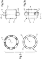
- Fig. 3a and 3b show two possible variants for performing a multi-level balancing a rotating unit 11, for example, a relatively wide grinding wheel.
- two separate balancing devices 39 are used, which are spaced apart in the axial direction and, for example, each attached to the rotating unit 11.
- a single balancing device 39 may be provided, which has two axially spaced balancing areas 41, wherein at each balancing area 41 at least one balancing mass is arranged. Also in this way can be balanced with a single balancing device 39 at two axially spaced balancing planes 43.
Landscapes
- Physics & Mathematics (AREA)
- General Physics & Mathematics (AREA)
- Testing Of Balance (AREA)
- Constituent Portions Of Griding Lathes, Driving, Sensing And Control (AREA)
Description
Die Erfindung betrifft eine Wuchteinrichtung, insbesondere einen Wuchtkopf oder einen Wuchtring, für ein elektromechanisches Auswuchtsystem für rotierende Einheiten, insbesondere für Spindeln von Werkzeugmaschinen, mit zumindest einer Wuchtmasse, die zur Kompensation einer Unwucht der Einheit verstellbar ist, und einer Antriebseinheit, insbesondere einem Elektromotor, zum Verstellen der Wuchtmasse. Solche Wuchteinrichtungen sind in den Dokumenten
Bei derartigen Wuchteinrichtungen besteht das Problem, dass ein zielgerichtetes automatisches Auswuchten nicht möglich ist. Es sind Wuchtköpfe bekannt, die verstellbare Gewichte aufweisen. Bei diesen bekannten Systemen kann aber nur nach dem so genannten "Trial and Error"-Prinzip gearbeitet werden, d.h. die Gewichte werden verstellt, und es wird das Verhalten des Gesamtsystems während dieses Verstellvorgangs hinsichtlich des Betrags und der Phase bzw. Winkelstellung des die jeweilige Unwucht kompensierenden, sich durch die Gewichte ergebenden Wuchtvektors beobachtet. Nachteilig an diesen Systemen ist insbesondere auch die lange Zeitdauer, die für den Auswuchtvorgang benötigt wird.In such balancing devices, the problem is that a targeted automatic balancing is not possible. There are balancing heads are known which have adjustable weights. In these known systems, however, can only be worked on the so-called "trial and error" principle, i. the weights are adjusted, and the behavior of the overall system during this adjustment process is observed with regard to the magnitude and the phase or angular position of the balance compensating the respective imbalance resulting from the weights. A disadvantage of these systems is in particular the long time required for the balancing process.
Ebenfalls bekannt sind "händische" Auswuchtverfahren, bei denen die Gewichte per Hand an geeignete Positionen gesetzt werden. Ein erfahrener Bediener kann auf diese Weise in Abhängigkeit von der jeweils gemessenen Reaktion des Gesamtsystems auf die momentan gewählte Lage der Gewichte eine zufrieden stellende Auswuchtung vornehmen. Für viele Anwendungen ist ein derartiges manuelles Verfahren allerdings vor allem aufgrund des damit verbundenen Zeitaufwands nicht akzeptabel.Also known are "manual" balancing methods in which the weights are manually set to appropriate positions. An experienced operator can thus make a satisfactory balance depending on the respective measured reaction of the entire system to the currently selected position of the weights. For many applications, however, such a manual method is not acceptable, above all because of the associated time expenditure.
Aufgabe der Erfindung ist es, eine Möglichkeit zum Auswuchten von rotierenden Einheiten zu schaffen, die eine hohe Zuverlässigkeit garantiert, möglichst wenig Zeit benötigt und automatisch durchführbar ist.The object of the invention is to provide a way of balancing rotating units, which guarantees high reliability, requires as little time as possible and is automatically feasible.
Die Lösung dieser Aufgabe erfolgt durch die Merkmale der Ansprüche 1 und 9.The solution of this object is achieved by the features of claims 1 and 9.
Durch die Vorgabe einer Mehrzahl von Positionen für die Wuchtmasse ist es möglich, die Wuchtmasse gezielt in eine für den jeweiligen Auswuchtvorgang benötigte Position zu verstellen. Es ist nicht erforderlich, zumindest einen wesentlichen Teil des insgesamt möglichen Verstellweges für die Wuchtmasse deshalb zu durchfahren, um durch Beobachten der Reaktion des rotierenden Gesamtsystems die jeweils optimale Auswuchtposition der Wuchtmasse erst zu ermitteln. Ein solches "Probieren" ist aufgrund der Erfindung nicht mehr nötig. Folglich ermöglicht es die Erfindung, aus der gemessenen Unwucht eine Sollposition für die Wuchtmasse zu berechnen und anschließend die Wuchtmasse direkt in diese Sollposition zu verfahren. Die Sollposition zeichnet sich dadurch aus, dass die in der Sollposition befindliche Wuchtmasse die gemessene Unwucht gerade kompensiert.By specifying a plurality of positions for the balancing mass, it is possible to selectively adjust the balancing mass in a position required for the respective balancing operation. It is therefore not necessary to drive through at least a substantial part of the total possible adjustment path for the balancing mass in order to first determine the respectively optimum balancing position of the balancing mass by observing the reaction of the rotating overall system. Such "tasting" is no longer necessary due to the invention. Consequently, the invention makes it possible to calculate a desired position for the balancing mass from the measured imbalance and then to move the balancing mass directly into this desired position. The setpoint position is characterized by the fact that the balancing mass located in the setpoint position just compensates the measured imbalance.
Der Vorteil der erfindungsgemäßen Wuchteinrichtung besteht insbesondere darin, dass sie aufgrund der gezielten Positionierbarkeit der Wuchtmasse ein schnelles und zielgerichtetes automatisches Auswuchten ermöglicht.The advantage of the balancing device according to the invention is, in particular, that it allows a fast and targeted automatic balancing due to the targeted positioning of the balancing mass.
Die Lösung der Aufgabe erfolgt außerdem durch ein elektromechanisches Auswuchtsystem für rotierende Einheiten, insbesondere für Spindeln von Werkzeugmaschinen, mit wenigstens einer in eine rotierende Einheit integrierte, an eine rotierende Einheit angebaute und/oder um eine rotierende Einheit herum montierte Wuchteinrichtung der hier angegebenen Art, und mit einer Messeinrichtung zum Bestimmen einer Unwucht der rotierenden Einheit.The object is also achieved by an electromechanical balancing system for rotating units, in particular for spindles of machine tools, with at least one integrated in a rotating unit, attached to a rotating unit and / or mounted around a rotating unit around balancing device of the type specified here, and with a measuring device for determining an imbalance of the rotating unit.
Des Weiteren wird die Aufgabe gelöst durch ein Verfahren nach Anspruch 14 zum, insbesondere automatischen, Auswuchten von rotierenden Einheiten mittels wenigstens einer Wuchteinrichtung der hier angegebenen Art, bei dem eine Unwucht der Einheit gemessen wird, aus der gemessenen Unwucht eine Sollposition für die Wuchtmasse berechnet wird, in der die Wuchtmasse die Unwucht kompensiert, und die Wuchtmasse in die Sollposition verstellt wird.Furthermore, the object is achieved by a method according to claim 14 for, in particular automatic, balancing of rotating units by means of at least one balancing device of the type specified here, in which an imbalance of the unit is measured from the measured imbalance, a desired position for the balancing mass is calculated in which the balancing mass compensates the imbalance, and the balancing mass is adjusted to the desired position.
Bevorzugte Weiterbildungen der Wuchteinrichtung, des Auswuchtsystems sowie des Auswuchtverfahrens sind in den abhängigen Ansprüchen, der Beschreibung sowie der Zeichnung angegeben.Preferred developments of the balancing device, the balancing system and the balancing method are specified in the dependent claims, the description and the drawings.
Bevorzugt ist die Wuchteinrichtung in die rotierende Einheit integrierbar, an die rotierende Einheit anbaubar und/oder um die rotierende Einheit herum montierbar. Integrierbare und/oder anbaubare Wuchteinrichtungen werden auch als Wuchtköpfe bezeichnet. Generell kann die Erfindung in Verbindung mit beliebig ausgestalteten elektromechanischen Wuchteinrichtungen realisiert werden.Preferably, the balancing device can be integrated into the rotating unit, can be mounted on the rotating unit and / or mounted around the rotating unit. Integratable and / or attachable balancing devices are also referred to as balancing heads. In general, the invention can be implemented in conjunction with any desired designed electromechanical balancing devices.
In einer weiteren Ausgestaltung der Erfindung kann vorgesehen sein, dass für die Positionen jeweils die Auswuchtwirkung der in der betreffenden Position befindlichen Wuchtmasse und/oder für jede Änderung der Position der Wuchtmasse die daraus resultierende Änderung der Auswuchtwirkung der Wuchtmasse bekannt oder bestimmbar ist. Die hierdurch gegebene Kenntnis des Verhaltens der Wuchteinrichtung in Bezug auf Verstellbewegungen der Wuchtmasse ermöglicht ein sehr schnelles Reagieren auf gemessene Unwuchten, indem die Wuchtmasse in der jeweils erforderlichen Weise verstellt wird.In a further embodiment of the invention it can be provided that for each of the positions the balancing effect of the balancing mass located in the relevant position and / or for each change of position the balancing mass is known or determinable the resulting change in the balancing effect of the balancing mass. The thus given knowledge of the behavior of the balancing device with respect to adjusting movements of the balancing mass allows a very rapid reaction to measured imbalances by the balancing mass is adjusted in the respectively required manner.
Eine weitere Verbesserung der Wuchteinrichtung wird dadurch erreicht, dass gemäß der Erfindung durch die Positionen jeweils die absolute Position der Wuchtmasse in einem bezüglich der Wuchteinrichtung festen Koordinatensystem vorgegeben oder bestimmbar ist. Ein derartiges absolutes System hat Vorteile gegenüber einem lediglich inkremental arbeitenden Positionierungssystem.A further improvement of the balancing device is achieved in that, according to the invention, the absolute position of the balancing mass in each case is predetermined or determinable by the positions in a fixed coordinate system with respect to the balancing device. Such an absolute system has advantages over a purely incremental positioning system.
Es ist deshalb möglich, die absolut(en) Position(en) der Wuchtmasse(n) zu bestimmen. Ein Vorteil hiervon ist, dass die Positionierungsbestimmung keine eigene Bewegung der Wuchtmasse(n) und/oder einer wie auch immer ausgebildeten Messeinrichtung oder Teilen davon erfordert, d.h. irgendwelche Relativbewegungen von Komponenten werden nicht benötigt.It is therefore possible to determine the absolute position (s) of the balancing mass (s). An advantage of this is that the positioning determination does not require its own movement of the balancing mass (s) and / or whatever the measuring device or parts thereof, i. any relative movements of components are not needed.
In der erfindungsgemäßen Wuchteinrichtung nach Anspruch 9 umfasst die Positioniereinrichtung eine Einrichtung zum Messen von Drehstellungen. Hierbei können in vorteilhafter Weise grundsätzlich bekannte Drehstellungsmesseinrichtungen verwendet werden, um für die Positionierbarkeit der Wuchtmasse zu sorgen. In der Einrichtung nach Anspruch 9 wird ein Permanentmagnet relativ zu einem in geeigneter Weise ausgebildeten Sensor drehbar angeordnet, wobei der Sensor in der Lage ist, die Drehstellung des Permanentmagneten mit einer Auflösung von deutlich unter 1° zu messen. Je nach konkreter Ausgestaltung der Wuchteinrichtung ist es möglich, derartige bekannte, insbesondere kostengünstig frei erhältliche Messeinrichtungen zur Positionsbestimmung bzw. Positionierung der Wuchtmasse einzusetzen.In the balancing device according to the invention according to claim 9, the positioning device comprises a device for measuring rotational positions. In this case, fundamentally known rotary position measuring devices can be used in an advantageous manner in order to ensure the positionability of the balancing mass. In the device according to claim 9, a permanent magnet is rotatably arranged relative to a suitably formed sensor, wherein the sensor is capable of measuring the rotational position of the permanent magnet with a resolution of well below 1 °. Depending on the specific embodiment of the balancing device, it is possible to use such known, in particular to use cost-freely available measuring devices for determining the position or positioning of the balancing mass.
In einem bevorzugten Ausführungsbeispiel der Erfindung sind die Positionen codiert und mittels eines Codelesers lesbar.In a preferred embodiment of the invention, the positions are coded and readable by means of a code reader.
Eine Möglichkeit zur Positionscodierung besteht nach einem weiteren Ausführungsbeispiel der Erfindung darin, die Positionen nach dem Gray-code-Prinzip zu codieren. Die Verwendung von Graycodes und die damit verbundenen Vorteile insbesondere bei der Übertragung von Informationen sind grundsätzlich bekannt, weshalb hierauf nicht näher eingegangen zu werden braucht. Besonders vorteilhaft im Hinblick auf die Verwendung zur Positionierung von Wuchtmassen ist die besondere Robustheit bzw. Fehlerunanfälligkeit der Informationsübertragung. Insbesondere kann erfindungsgemäß die Codierung der Positionen nach dem Single-Track-Graycode-Prinzip erfolgen.One possibility for position coding according to a further embodiment of the invention is to encode the positions according to the Gray code principle. The use of Graycodes and the associated advantages in particular in the transmission of information are basically known, which is why it need not be discussed in detail. Particularly advantageous with regard to the use for the positioning of balancing masses is the particular robustness or error-susceptibility of the information transmission. In particular, the coding of the positions according to the invention can be carried out according to the single-track Graycode principle.
Die praktische Umsetzung einer derartigen Codierung kann in grundsätzlich beliebiger Art und Weise erfolgen. Lediglich beispielhaft sei erwähnt, dass als Codeträger ein in Umfangsrichtung magnetisierter Ringstreifen dienen kann, wobei als Codeleser ein entsprechend ausgebildeter Ringstreifen dient, der eine Mehrzahl von in Umfangsrichtung verteilt angeordneten, auf die Art und Weise der Magnetisierung ansprechenden Sensoren aufweist, die beispielsweise in Form von Hall-Sonden vorgesehen sind.The practical implementation of such coding can be done in basically any way. Merely by way of example, it should be mentioned that a circumferentially magnetized ring strip can serve as the code carrier, wherein a correspondingly formed ring strip serves as the code reader, which has a plurality of circumferentially distributed, responsive to the type of magnetization sensors, for example in the form of Hall probes are provided.
Des Weiteren kann erfindungsgemäß vorgesehen sein, dass einer Verstellbewegung der Wuchtmasse eine Bewegung eines Codeträgers relativ zu einem Codeleser zugeordnet ist, wobei diese Bewegung eine Änderung des lesbaren Positionscodes zur Folge hat. Der Codeträger und die Wuchtmasse können beispielsweise mechanisch zwangsgekoppelt sein, so dass nur eine gemeinsame Bewegung von Wuchtmasse und Codeträger möglich ist.Furthermore, it can be provided according to the invention that an adjustment movement of the balancing mass is associated with a movement of a code carrier relative to a code reader, this movement resulting in a change of the readable position code. The code carrier and the balancing mass For example, they may be mechanically positively coupled, so that only a joint movement of balancing mass and code carrier is possible.
Eine besonders einfache und gleichzeitig zuverlässige mögliche Ausgestaltung sieht vor, dass der Codeträger wenigstens eine, insbesondere genau eine, ringförmige Codespur umfasst. Im Falle mehrerer Wuchtmassen kann jeder Wuchtmasse eine beispielsweise ringförmige Codespur zugeordnet sein.A particularly simple and at the same time reliable possible embodiment provides that the code carrier comprises at least one, in particular exactly one, annular code track. In the case of several balancing masses each balancing mass may be associated with an example annular code track.
Die Wuchteinrichtung kann eine Mehrzahl von Wuchtmassen umfassen, wobei insbesondere genau zwei Wuchtmassen vorgesehen sind. Vorzugsweise sind die Wuchtmassen unabhängig voneinander verstellbar. Wenn wenigstens zwei Wuchtmassen vorgesehen sind, kann erfindungsgemäß der erforderliche Wuchtvektor sehr schnell sowohl hinsichtlich Betrag und Phase bzw. Richtung eingestellt werden. Die einzelnen Wuchtmassen der Wuchteinrichtung können in axialer Richtung zueinander versetzt angeordnet sein. Alternativ ist eine Anordnung der Wuchtmassen mit gleicher axialer Lage möglich, was den Vorteil hat, dass keine axial beabstandeten Ausgleichsebenen existieren und folglich keine Momentenunwucht entsteht.The balancing device may comprise a plurality of balancing masses, wherein in particular exactly two balancing masses are provided. Preferably, the balancing masses are independently adjustable. If at least two balancing masses are provided, according to the invention the required balancing vector can be adjusted very quickly both in terms of magnitude and phase or direction. The individual balancing masses of the balancing device can be arranged offset from one another in the axial direction. Alternatively, an arrangement of the balancing masses with the same axial position is possible, which has the advantage that no axially spaced balancing planes exist and consequently no moment unbalance arises.
Bevorzugt ist die erfindungsgemäße Wuchteinrichtung zur Ausführung eines Mehr-Ebenen-Auswuchtens geeignet, wobei die Wuchteinrichtung wenigstens zwei an längs einer Achse der Wuchteinrichtung voneinander beabstandeten Stellen angeordnete Anordnungen von jeweils wenigstens einer Wuchtmasse aufweist. Ein Mehr-Ebenen-Auswuchten, das in der Praxis häufig erforderlich ist, war bislang schwer handhabbar, und zwar aufgrund der unvermeidbaren Rückkopplung zwischen den beiden Auswuchtstellen, d.h. eine an der einen Auswuchtstelle vorgenommene Veränderung des Wuchtvektors hat eine Veränderung der Verhältnisse an der anderen Auswuchtstelle zur Folge, und umgekehrt. Aufgrund der durch die erfindungsgemäße Positionierbarkeit der Wuchtmasse gegebenen Vorhersagbarkeit des Verhaltens des Systems bei einem Verstellen der Wuchtmasse kann man selbst derartige komplexe Auswuchtsituationen in den Griff bekommen und den insgesamt erforderlichen Wuchtvektor schnell und automatisch zielgerichtet einstellen.Preferably, the balancing device according to the invention is suitable for carrying out a multi-level balancing, wherein the balancing device has at least two arrangements of at least one balancing mass arranged at locations spaced from each other along an axis of the balancing device. A multi-level balancing, which is often required in practice, has hitherto been difficult to handle, due to the unavoidable feedback between the two balancing points, ie a change in the balancing vector made at the one balancing point has a change in the ratios at the balancing point another balancing point result, and vice versa. Due to the predictability of the behavior of the system given an adjustment of the balancing mass by the positionability of the balancing mass according to the invention, even such complex balancing situations can be controlled and the target balancing vector can be set quickly and automatically in a targeted manner.
In einer weiteren bevorzugten Ausgestaltung der Erfindung ist in die Wuchteinrichtung eine Prozesseinrichtung integriert, die zumindest dazu ausgebildet ist, in Abhängigkeit von eine gemessene Unwucht betreffenden Signalen und/oder Daten zumindest einen Teil des die Wuchteinrichtung mit einbeziehenden Auswuchtprozesses durchzuführen. Hierdurch ist die Wuchteinrichtung im Hinblick auf die hierfür erforderlichen Prozesse selbst dazu in der Lage, zumindest einen Teil des erforderlichen Auswuchtprozesses durchzuführen. Dieser Aspekt des Auswuchtens ist Gegenstand einer anderen Patentanmeldung der Anmelderin, so dass hierauf nicht näher eingegangen wird.In a further preferred embodiment of the invention, a process device is integrated into the balancing device, which is designed at least to carry out at least part of the balancing process involving the balancing device as a function of a measured imbalance-related signals and / or data. As a result, the balancing device is in a position to carry out at least part of the required balancing process with regard to the processes required for this purpose. This aspect of balancing is the subject of another patent application of the Applicant, so that will not be discussed in detail.
Die Prozesseinrichtung ist insbesondere zusätzlich dazu ausgebildet, Daten und/oder Signale zu erfassen, zu verarbeiten und/oder zu speichern und/oder Prozesse auszuführen, die nicht den Auswuchtprozess betreffen. Hierdurch kann eine ohnehin für den Auswuchtprozess benötigte Infrastruktur für andere Zwecke genutzt werden.The process device is in particular additionally designed to acquire, process and / or store data and / or signals and / or execute processes which do not relate to the balancing process. As a result, an infrastructure that is required anyway for the balancing process can be used for other purposes.
Bei dem erfindungsgemäßen Auswuchtsystem kann vorgesehen sein, dass zur Steuerung eines Auswuchtprozesses der Wuchteinrichtung und/oder zur Kommunikation mit einer in die Wuchteinrichtung integrierten Prozesseinrichtung eine externe Steuereinrichtung vorgesehen ist. Diese externe Steuereinrichtung kann außerdem zur Energieversorgung der Wuchteinrichtung und/oder zur Kommunikation mit einer übergeordneten Maschinensteuerung dienen.In the balancing system according to the invention it can be provided that an external control device is provided for controlling a balancing process of the balancing device and / or for communication with a process device integrated in the balancing device. This external control device can also be used to power the Balancing device and / or serve for communication with a higher-level machine control.
Bevorzugt ist zur Energieversorgung der Wuchteinrichtung und/oder zur Kommunikation zwischen einer externen Steuereinrichtung und einer in die Wuchteinrichtung integrierten Prozesseinrichtung eine berührungslos arbeitende Übertragungseinrichtung vorgesehen. Eine derartige kontaktfreie Übertragung ist an sich bekannt, so dass hierauf nicht näher eingegangen zu werden braucht.Preferably, a non-contact transmission device is provided for supplying power to the balancing device and / or for communication between an external control device and a processing device integrated in the balancing device. Such a contactless transmission is known per se, so that need not be discussed further hereon.
Das Auswuchtsystem kann zur Ausführung eines Mehr-Ebenen-Auswuchtens eine Mehrzahl von Wuchteinrichtungen umfassen, die dazu ausgebildet sind, an längs der Drehachse der Einheit voneinander beabstandeten Stellen angeordnet zu werden. Für das in der Praxis wichtige Mehr-Ebenen-Auswuchten kann also eine Mehrzahl von Wuchteinrichtungen vorgesehen sein, wobei es - wie vorstehend bereits erwähnt - auch möglich ist, hierfür eine einzige Wuchteinrichtung vorzusehen, die mehrere Wuchtmassenanordnungen umfasst, die axial beabstandet sind.The balancing system may comprise a plurality of balancing means adapted to be arranged at locations spaced apart along the axis of rotation of the unit for performing multi-level balancing. For the important in practice important multi-level balancing may therefore be provided a plurality of balancing devices, and it is - as already mentioned - also possible to provide for this purpose a single balancing device comprising a plurality of balancing mass arrangements which are axially spaced.
Bei dem erfindungsgemäßen Auswuchtverfahren ist insbesondere vorgesehen, dass das Verfahren einschließlich des Verstellens der Wuchtmasse bei rotierender Einheit durchgeführt wird. Vorzugsweise erfolgt das Auswuchten bei mit Betriebs- oder Nenndrehzahl rotierender Einheit.In the balancing method according to the invention, provision is made in particular for the method, including the adjustment of the balancing mass, to be carried out while the unit is rotating. Preferably, the balancing is carried out at rotating at operating or rated speed unit.
Die Erfindung betrifft außerdem eine während des Betriebs rotierende Einheit, insbesondere eine Spindel einer Werkzeugmaschine, mit wenigstens einer Wuchteinrichtung der hier angegebenen Art oder mit einem Auswuchtsystem der hier angegebenen Art.The invention also relates to a rotating unit during operation, in particular a spindle of a machine tool, with at least one balancing device of the type specified here or with a balancing system of the type specified here.
Ferner betrifft die Erfindung eine Werkzeugmaschine mit wenigstens einer Wuchteinrichtung der hier angegebenen Art oder mit einem Auswuchtsystem der hier angegebenen Art.Furthermore, the invention relates to a machine tool with at least one balancing device of the type specified here or with a balancing system of the type specified here.
Die Erfindung wird im Folgenden beispielhaft unter Bezugnahme auf die Zeichnung beschrieben. Es zeigen:
- Fig. 1
- schematisch eine Ausführungsform eines erfindungsgemäßen Auswuchtsystems an einer während des Betriebs rotierenden Einheit,
- Fig. 2
- schematisch eine Ausführungsform eines Teils einer Positioniereinrichtung gemäß der Erfindung, und
- Fig. 3a und 3b
- schematisch zwei Möglichkeiten zur Durchführung eines Mehr-Ebenen-Auswuchtens.
- Fig. 1
- 1 schematically shows an embodiment of a balancing system according to the invention on a unit rotating during operation,
- Fig. 2
- schematically an embodiment of a part of a positioning device according to the invention, and
- Fig. 3a and 3b
- schematically two ways to perform a multi-level balancing.
In der Praxis ist die Spindel 11 Bestandteil einer Werkzeugmaschine, die einer übergeordneten Maschinensteuerung 29 zugeordnet ist. Die Maschinensteuerung 29 kommuniziert in dem dargestellten Ausführungsbeispiel mit einer externen Steuereinrichtung 25, die Bestandteil eines erfindungsgemäßen Auswuchtsystems ist. Der Umfang der Aufgaben, die von der externen Steuereinrichtung 25 übernommen werden, kann im Rahmen der Erfindung variieren. So kann beispielsweise vorgesehen sein, dass für die Positionierung der Wuchtmassen, worauf nachstehend näher eingegangen wird, erforderliche Berechnungen von der externen Steuereinrichtung 25 vorgenommen werden. Gleichwohl ist es möglich, dass derartige Berechnungen und weitere Aufgaben von einer in die Wuchteinrichtung integrierten, während des Betriebs rotierenden Prozesseinrichtung 21 durchgeführt werden.In practice, the
Bei der Steuereinrichtung 25 handelt es sich um eine "externe" Komponente insofern, als die Steuereinrichtung 25 nicht Bestandteil des rotierenden Systems ist, sondern der stationären Seite zugeordnet ist.The
Das erfindungsgemäße Auswuchtsystem umfasst des Weiteren eine Wuchteinrichtung, die in dem hier dargestellten Ausführungsbeispiel in die Spindel integriert ist und im Folgenden auch als Wuchtkopf bezeichnet wird. Wie eingangs bereits erwähnt, ist eine derartige Ausgestaltung der Wuchteinrichtung nicht zwingend, sondern die Erfindung umfasst auch auf andere Art und Weise mit der jeweiligen rotierenden Einheit zusammenwirkende Wuchteinrichtungen, beispielsweise anbaubare Wuchteinrichtungen oder Wuchtringe, die die jeweilige rotierende Einheit oder einen Bestandteil davon mittenfrei umschließen. Derartige Wuchtringe müssen nicht in Form eines geschlossenen Ringes vorliegen. Grundsätzlich ist es möglich, derartige Wuchteinrichtungen in Form von Ringsegmenten, die beispielsweise eine etwa C-förmige Struktur aufweisen, vorzusehen.The balancing system according to the invention further comprises a balancing device, which is integrated into the spindle in the exemplary embodiment shown here and is also referred to below as a balancing head. As already mentioned, such a design of the balancing device is not mandatory, but the invention also includes balancing devices cooperating with the respective rotating unit in other ways, for example attachable balancing devices or balancing rings which enclose the respective rotating unit or a component thereof in the middle. Such balancing rings need not be in the form of a closed ring. In principle, it is possible to use such balancing devices in the form of ring segments, for example, have an approximately C-shaped structure to provide.
Die Energieversorgung der hier in die Spindel 11 integrierten Wuchteinrichtung sowie die Kommunikation zwischen der externen Steuereinrichtung 25 und der Wuchteinrichtung, insbesondere der in die Wuchteinrichtung integrierten Prozesseinrichtung 21, erfolgt durch eine berührungslos arbeitende Übertragungseinrichtung 27. Wie durch die beiden, mit entgegengesetzt gerichteten Pfeilsymbolen versehenen Linien angedeutet, ist mittels der Übertragungseinrichtung 27 eine bidirektionale Kommunikation mit der in die Spindel 11 integrierten Wuchteinrichtung möglich. Dies eröffnet mannigfaltige, bislang nicht in Verbindung mit Wuchteinrichtungen realisierbare Anwendungsmöglichkeiten.The power supply of the integrated here in the
Die hier in die Spindel 11 integrierte Wuchteinrichtung umfasst die bereits erwähnte integrierte Prozesseinrichtung 21 sowie zwei jeweils auf einer Kreisbahn um die Drehachse 45 bewegbare Wuchtmassen 13, denen jeweils ein Elektromotor 15 als Antriebseinheit mit einem entsprechenden Getriebe 47 zugeordnet ist. Die Darstellung der Anordnung dieser Komponenten in
Der Vollständigkeit halber sei erwähnt, dass prinzipiell auch lediglich eine einzige verstellbare Wuchtmasse vorgesehen sein kann, die insbesondere nicht nur in Umfangsrichtung, sondern auch in radialer Richtung verstellbar ist, um den jeweils benötigten Wuchtvektor sowohl hinsichtlich Richtung als auch Betrag einstellen zu können.For the sake of completeness, it should be mentioned that, in principle, only a single adjustable balancing mass can be provided, which is adjustable not only in the circumferential direction but also in the radial direction, in order to be able to set the respectively required balancing vector both in terms of direction and magnitude.
Des Weiteren umfasst die Wuchteinrichtung eine Positioniereinrichtung 17, von der hier ein als geschlossener Ringstreifen ausgebildeter Codeträger 19 dargestellt ist. Auf die Positioniereinrichtung 17 wird nachstehend in Verbindung mit
Der hier dargestellte Codering 19 ist einer der Wuchtmassen 13 zugeordnet und gemeinsam mit dieser Wuchtmasse 13 um die Drehachse 45 verdrehbar. Eine Verstellbewegung der Wuchtmasse 13 mittels des zugeordneten Elektromotors 15 hat folglich eine Bewegung des Coderings 19 zur Folge, und zwar relativ zu einem Codeleser 37 (vgl.
Der anderen Wuchtmasse 13 ist ebenfalls ein entsprechender, nicht dargestellter Codering zugeordnet, der gemeinsam mit dieser Wuchtmasse 13 bewegbar ist. Die beiden Wuchtmassen 13 und somit die beiden Coderinge 19 sind unabhängig voneinander bewegbar, d.h. die Elektromotoren 15 sind unabhängig voneinander ansteuerbar, so dass die beiden Wuchtmassen 13 unabhängig voneinander in eine jeweils vorgegebene Position verstellt werden können.The other balancing
Das erfindungsgemäße Auswuchtsystem umfasst des Weiteren eine Messeinrichtung 23, beispielsweise einen Schwingungsaufnehmer, der dazu dient, eine vorhandene Unwucht U zu bestimmen. Die Art und Weise der Ausgestaltung der Messeinrichtung 23 ist grundsätzlich beliebig.The balancing system according to the invention further comprises a measuring
Des Weiteren umfasst das Auswuchtsystem einen Drehsignalgeber, der einen die Drehzahl der rotierenden Spindel repräsentierenden Wert bereitstellt.Furthermore, the balancing system comprises a rotary signal generator which provides a value representing the rotational speed of the rotating spindle.
Der Schwingungsaufnehmer 23, der Drehsignalgeber 49 und der Sensor 35 können, wie durch gestrichelte Linien angedeutet, mit der externen Steuereinrichtung 25 kommunizieren, die für die nötige Datenerfassung, Signalaufbereitung und Signalverarbeitung sorgt, um auf der Basis dieser Informationen zumindest den wesentlichen Teil des Auswuchtprozesses zu steuern. Alternativ kann vorgesehen sein, dass die erwähnten Komponenten direkt mit der in die Wuchteinrichtung integrierten Prozesseinrichtung 21 verbunden sind, so dass eine Übertragung der Informationen an die externe Steuereinrichtung 25 nicht erforderlich ist. Insbesondere für diesen Fall ist die integrierte Prozesseinrichtung 21 mit einer Erfassungs- und Verarbeitungseinrichtung versehen, mit der die eingehenden Signale und/oder Daten erfasst und verarbeitet werden können. Auf diese Weise ist die hier in die Spindel 11 integrierte Wuchteinrichtung aufgrund ihrer integrierten Prozesseinrichtung 21 selbst in der Lage, die als Basis für die Steuerung des Auswuchtprozesses nötigen Informationen zu beschaffen bzw. zu generieren. Insofern handelt es sich bei der Wuchteinrichtung um eine "intelligente" Wuchteinrichtung, die nicht lediglich extern generierte Steuersignale für die Elektromotoren 15 der Wuchtmassen 13 empfängt.The
Des Weiteren ist die in die Wuchteinrichtung integrierte Prozesseinrichtung 21 in diesem Ausführungsbeispiel mit einer Speichereinrichtung 33 versehen. Hierdurch kann die Prozesseinrichtung 21 grundsätzlich beliebige Daten speichern, wobei diese Daten den Auswuchtprozess betreffen können, dies aber nicht zwingend erforderlich ist. Die zu speichernden Daten können beispielsweise den Betrieb und/oder den Zustand der Spindel 11 oder des mit der Spindel 11 verbundenen Werkzeugs auch im Hinblick auf auswuchtfremde Aspekte betreffen. Die Prozesseinrichtung 21 und somit die hier in die Spindel 11 integrierte Wuchteinrichtung dienen dadurch als "Fahrtenschreiber" oder "Datenlogger" für grundsätzlich beliebige Informationen.Furthermore, the
Es ist auch möglich, in dem Datenspeicher 33 beispielsweise die Betriebssicherheit oder eine bestimmungsgemäße Verwendung des jeweiligen Werkzeugs betreffende Daten abzulegen. So weisen beispielsweise Schleifscheiben eine zulässige Maximaldrehzahl auf, der sich die Schleifscheibe aufgrund ihrer betriebsbedingten Abnutzung im Laufe der Betriebszeit nähert, da die wirksame Umfangsgeschwindigkeit der Schleifscheibe am Werkstück möglichst konstant bleiben soll. Indem dem Gesamtsystem derartige sicherheits- bzw. betriebsrelevante Daten mittels der Speichereinrichtung 33 der Prozesseinrichtung 21 zur Kenntnis gebracht werden, können diese Informationen automatisch während des Betriebs berücksichtigt werden. Diese Überwachung kann dann, sobald die betreffende Bedingung erfüllt ist, eine vorgegebene Reaktion auslösen, beispielsweise ein Warnsignal erzeugen.It is also possible to store in the
Zur Durchführung des Auswuchtprozesses wird in dem hier beschriebenen Ausführungsbeispiel zunächst die vorhandene Unwucht U der Spindel 11 bzw. des die Spindel 11 und insbesondere das jeweilige Werkzeug umfassenden rotierenden Gesamtsystems bestimmt. Entweder mittels der externen Steuereinrichtung 25 oder der in die Wuchteinrichtung integrierten Prozesseinrichtung 21 werden aus der gemessenen Unwucht U Sollsignale für die beiden Wuchtmassen 13 berechnet. Für jede Position der erfindungsgemäßen Wuchteinrichtung ist die Auswuchtwirkung W der an dieser Position befindlichen Wuchtmasse 13 bekannt. Für jede Positionierung der beiden Wuchtmassen 13 ist folglich bekannt, wie sich die beiden Teil-Wuchtvektoren W zu einem resultierenden Wuchtvektor B addieren, so dass ausgehend von der durch die Messung hinsichtlich Richtung und Betrag bekannten Unwucht U diejenigen Sollpositionen für die beiden Massen berechnet werden können, die den gewünschten, die Unwucht U kompensierenden resultierenden Wuchtvektor W zur Folge haben.To carry out the balancing process, in the exemplary embodiment described here, first of all the existing imbalance U of the
Die Positionen, an denen sich die Wuchtmassen 13 sowohl bei einem Einschalten des Systems als auch während des Verstellvorgangs befinden, sind aufgrund der Positioniereinrichtung 17 eindeutig identifizierbar. Aus diesen eindeutig identifizierbaren Ist-Positionen der Wuchtmassen 13 und den zuvor berechneten Sollpositionen können die erforderlichen Verstellwege für die Wuchtmassen 13 berechnet werden.The positions at which the
Bei einer Verstellbewegung der betreffenden Wuchtmasse 13 (vgl.
In der Praxis können problemlos Ortsauflösungen mit mehreren Tausend Drehstellungen über einen Winkel von 360° erreicht werden.In practice, spatial resolutions with several thousand rotational positions over an angle of 360 ° can be achieved without problems.
Es sei an dieser Stelle erwähnt, dass das Zusammenwirken von magnetisierten Segmenten eines Kreisrings mit einer entsprechenden Anordnung von Hall-Sonden nur ein Beispiel für die Nutzung des Graycode-Prinzips darstellt. Es sind diesbezüglich grundsätzlich beliebige Ausgestaltungen der Positioniereinrichtung möglich. Auch die Nutzung des Gray-Code-Prinzips selbst ist nicht zwingend.It should be noted at this point that the interaction of magnetized segments of a circular ring with a corresponding arrangement of Hall probes is only one example of the use of the Graycode principle. In this regard, basically any desired configurations of the positioning device are possible. The use of the Gray code principle itself is not mandatory.
Die
Um an in axialer Richtung beabstandeten Ausgleichsebenen 43 auswuchten zu können, können gemäß
Alternativ kann gemäß
Die Wahl zwischen diesen beiden Varianten gemäß
- 1111
- rotierende Einheitrotating unit
- 1313
- Wuchtmassebalancing mass
- 1515
- Antriebseinheit, ElektromotorDrive unit, electric motor
- 1717
- Positioniereinrichtungpositioning
- 1919
- Codeträgercode carrier
- 2121
- Prozesseinrichtungprocess means
- 2323
- Messeinrichtung, SchwingungsaufnehmerMeasuring device, vibration sensor
- 2525
- externe Steuereinrichtungexternal control device
- 2727
- Übertragungseinrichtungtransmission equipment
- 2929
- Maschinensteuerungmachine control
- 3131
- Erfassungs- und VerarbeitungseinrichtungDetection and processing device
- 3333
- Speichereinrichtungmemory device
- 3535
- Messeinrichtung, SensorMeasuring device, sensor
- 3737
- Codelesercode reader
- 3939
- Wuchteinrichtungbalancer
- 4141
- Wuchtbereichimpact area
- 4343
- Ausgleichsebenebalancing plane
- 4545
- Bezugsachse/DrehachseReference axis / rotational axis
- 4747
- Getriebetransmission
- 4949
- DrehsignalgeberRotation signal generator
- 5151
- Hall-Sonden/SensorenHall probes / sensors
- UU
- Unwuchtunbalance
- WW
- Auswuchtwirkungbalancing effect
- BB
- resultierender Wuchtvektorresulting balance vector
Claims (15)
- A balancing device, in particular a balancing head or a balancing ring, for an electromechanical balancing system for rotating units (11), in particular for spindles of machine tools, comprising at least one balancing mass (13) which is adjustable for compensation of an imbalance (U) of the unit (11);
a drive unit (15), in particular an electric motor, for adjusting the balancing mass (13); and
a positioning device (17) by which a plurality of rotational positions are predefined into which the balancing mass (13) can be adjusted, wherein the positioning device (17) comprises a device (19, 37), rotating with the unit (11) during operation, for measuring the rotational positions by which the respective absolute rotational position of the balancing mass (13) in a coordinate system fixed with respect to the balancing device is predefined or can be determined,
characterized in that
the rotating device (19, 37) comprises two components (19, 37) rotatable relative to one another,
with a rotational movement of the one component (19) relative to the other component (37) being associated with an adjustment movement of the balancing mass (13), and
with the absolute rotational position of the balancing mass (13) being predefined or able to be determined by the relative position of the two components (19, 37). - A balancing device in accordance with claim 1,
characterized in that
the balancing device can be integrated into the unit (11), can be attached to the unit (11) and/or can be mounted about the unit (11). - A balancing device in accordance with claim 1 or claim 2,
characterized in that
the respective balancing effect (W) of the balancing mass (13) located in the respective rotational position is known or can be determined for the rotational positions and/or the change of the balancing effect (W) of the balancing mass (13) resulting from each change of the rotational position of the balancing mass (13) is known or can be determined for each such change. - A balancing device in accordance with any one of the preceding claims,
characterized in that
the rotational positions are encoded and can be read by means of a code reader (37); and/or
in that the rotational positions are encoded according to the Gray code principle, in particular according to the single-track Gray code principle. - A balancing device in accordance with claim 4,
characterized in that
a movement of a code carrier (19) relative to a code reader (37) which has the consequence of a change of the legible rotational position code is associated with an adjustment movement of the balancing mass (13), with the code carrier (19) in particular comprising at least one, in particular exactly one, annular code track. - A balancing device in accordance with any one of the preceding claims,
characterized in that
the balancing device comprises a plurality of balancing masses (13), in particular exactly two balancing masses (13), with the balancing masses (13) being adjustable independently of one another. - A balancing device in accordance with any one of the preceding claims,
characterized in that,
for carrying out a multi-planar balancing, the balancing device comprises at least two arrangements of respectively at least one balancing mass (13) arranged at points spaced apart from one another along an axis of the balancing device. - A balancing device in accordance with any one of the preceding claims,
characterized in that
a process device (21) is provided which is integrated into the balancing device and which is at least configured to carry out at least a part of a balancing process including the balancing device in dependence on signals and/or data relating to a measured imbalance (U), with in particular the process device (21) additionally being configured to detect, to process and/or to store data and/or signals and/or to carry out processes which do not relate to the balancing process. - A balancing device, in particular a balancing head or a balancing ring, for an electromechanical balancing system for rotating units (11), in particular for spindles of machine tools, comprising at least one balancing mass (13) which is adjustable for compensation of an imbalance (U) of the unit (11);
a drive unit (15), in particular an electric motor, for adjusting the balancing mass (13); and
a positioning device (17) by which a plurality of rotational positions are predefined into which the balancing mass (13) can be adjusted, wherein the positioning device (17) comprises a device (19, 37), rotating with the unit (11) during operation, for measuring the rotational positions by which the respective absolute rotational position of the balancing mass (13) in a coordinate system fixed with respect to the balancing device is predefined or can be determined, characterized in that
a device for measuring the rotational positions comprises a permanent magnet and a sensor, with the permanent magnet being arranged rotatable relative to the sensor, and with the sensor being able to measure the rotational position of the permanent magnet, in particular with a resolution of considerably less than 1°,
with a rotational movement of the permanent magnet relative to the sensor being associated with an adjustment movement of the balancing mass (13), and with the absolute rotational position of the balancing mass (13) being predefined or able to be determined by the relative position of the permanent magnet with respect to the sensor. - An electromechanical balancing system for rotating units (11), in particular for spindles of machine tools, comprising at least one balancing device in accordance with any one of the preceding claims integrated into a unit (11), attached to a unit (11) and/or mounted about a unit (11); and
a measuring device (23) for determining an imbalance of the unit (11),
with an external control device (25) in particular being provided for controlling a balancing process of the balancing device and/or for communicating with a process device (21) integrated into the balancing device. - A balancing system in accordance with claim 10,
characterized in that
a contactlessly working transfer device (27) is provided for the energy supply of the balancing device and/or for the communication between an external control device (25) and a process device (21) integrated into the balancing device; and/or
in that an external control device (25) and/or a process device (21) integrated into the balancing device is/are configured to calculate, in particular automatically, a desired rotational position for the balancing mass (13), in which the balancing mass (13) compensates the imbalance (U), from a measured imbalance (U) of the unit (11) and to adjust the balancing mass (13) into the desired rotational position. - A balancing system in accordance with claim 10 or claim 11,
characterized in that
a plurality of balancing devices are provided for carrying out a multi-planar balancing and are configured to be arranged at points spaced apart from one another along the axis of rotation of the unit (11). - A unit (11) rotating during operation, in particular a spindle of a machine tool, comprising at least one balancing device in accordance with any one of the claims 1 to 9 or a balancing system in accordance with any one of the claims 10 to 12; and/or
a machine tool comprising at least one balancing device in accordance with any one of the claims 1 to 9 or a balancing system in accordance with any one of the claims 10 to 12. - A method for the balancing, in particular for the automatic balancing, of rotating units (11), in particular spindles of machine tools, by means of at least one balancing device in accordance with any one of the claims 1 to 9 integrated into the unit (11), attached to the unit (11) and/or mounted about the unit (11), in which an imbalance (U) of the unit (11) is measured;
a desired rotational position for the balancing mass (13) in which the balancing mass (13) compensates the imbalance (U) is calculated from the measured imbalance (U);
the balancing mass (13) is adjusted into the desired rotational position; and
wherein the respective absolute rotational position of the balancing mass (13) in a coordinate system fixed with respect to the balancing device is predefined or determined. - A method in accordance with claim 14,
characterized in that
the method, including the adjustment of the balancing mass (13), is carried out with a rotating unit (11), in particular a unit rotating at the operating speed; and/or
in that, for carrying out a multi-planar balancing, the method is carried out by means of at least two balancing devices arranged at points spaced apart from one another along the axis of rotation of the unit (11) or by means of arrangements of respectively at least one balancing mass (13) integrated into a balancing device.
Applications Claiming Priority (2)
| Application Number | Priority Date | Filing Date | Title |
|---|---|---|---|
| DE200810028892 DE102008028892A1 (en) | 2008-06-18 | 2008-06-18 | Balancing device, balancing system and balancing method |
| PCT/EP2009/004398 WO2009156094A1 (en) | 2008-06-18 | 2009-06-18 | Balancing device, balancing system, and balancing method |
Publications (2)
| Publication Number | Publication Date |
|---|---|
| EP2297563A1 EP2297563A1 (en) | 2011-03-23 |
| EP2297563B1 true EP2297563B1 (en) | 2018-09-26 |
Family
ID=41057315
Family Applications (1)
| Application Number | Title | Priority Date | Filing Date |
|---|---|---|---|
| EP09768943.4A Active EP2297563B1 (en) | 2008-06-18 | 2009-06-18 | Balancing device, balancing system, and balancing method |
Country Status (4)
| Country | Link |
|---|---|
| EP (1) | EP2297563B1 (en) |
| DE (1) | DE102008028892A1 (en) |
| ES (1) | ES2703275T3 (en) |
| WO (1) | WO2009156094A1 (en) |
Families Citing this family (6)
| Publication number | Priority date | Publication date | Assignee | Title |
|---|---|---|---|---|
| WO2011140016A1 (en) * | 2010-05-03 | 2011-11-10 | Lord Corporation | Computer system and program product for balancing rotating machines |
| EP2717032B1 (en) * | 2012-10-02 | 2020-03-04 | Balance Systems S.r.L. | Balancing Process and Device for a Rotating Body |
| CN103115724B (en) * | 2013-01-29 | 2015-05-20 | 深圳大学 | Online dynamic balance compensation device and method for high-speed motorized spindles |
| DE102015223061A1 (en) | 2015-11-23 | 2017-05-24 | Dr. Johannes Heidenhain Gesellschaft Mit Beschränkter Haftung | Angle measuring device and method for operating an angle measuring device |
| DE102017117059B4 (en) * | 2017-07-26 | 2026-05-07 | Franz Haimer Maschinenbau Kg | MACHINE TOOL SYSTEM WITH AUTOMATIC BALANCING PROTOCOL ANALYSIS |
| JP7525629B2 (en) * | 2020-09-30 | 2024-07-30 | ファナック株式会社 | Machine Tools |
Citations (4)
| Publication number | Priority date | Publication date | Assignee | Title |
|---|---|---|---|---|
| DE2345664A1 (en) | 1973-09-11 | 1975-07-24 | Szerszamgepipari Muevek | BALANCING DEVICE WITH TWO OR MORE BALANCING LEVELS FOR DYNAMIC BALANCING OF MACHINE PARTS, IN PARTICULAR WIDE GRINDING BODIES DURING THEIR CIRCULATION |
| EP0409050A2 (en) | 1989-07-20 | 1991-01-23 | BALANCE SYSTEMS S.r.l. | Rotating mass dynamic balancing device in particular for grinding wheels |
| WO1996017294A1 (en) | 1994-11-29 | 1996-06-06 | Balance Dynamics Corporation | Electromagnetically actuated rotating machine unbalance compensator |
| EP1870198A1 (en) | 2006-06-23 | 2007-12-26 | Marposs Societa' Per Azioni | Control system and balancing device for a machine tool with rotating tools |
Family Cites Families (16)
| Publication number | Priority date | Publication date | Assignee | Title |
|---|---|---|---|---|
| DE3720746A1 (en) * | 1987-06-23 | 1989-01-05 | Dittel Walter Gmbh | BALANCING DEVICE FOR OBJECTS CARRIED BY A ROTATING SHAFT |
| DE3742149A1 (en) * | 1987-12-09 | 1989-06-22 | Studio S Ges Fuer Elektronik D | Method and device for compensating the imbalance of rotating bodies (solids of revolution) |
| DE4215723A1 (en) * | 1992-05-13 | 1993-11-18 | Dittel Walter Gmbh | Method for controlling a grinding machine |
| DE4222535A1 (en) * | 1992-07-09 | 1994-01-13 | Hofmann Werkstatt Technik | Device for balancing a grinding wheel rotatable about an axis of rotation |
| IT1258192B (en) * | 1992-08-03 | 1996-02-21 | Marposs Spa | DYNAMIC BALANCING DEVICE OF A ROTATING BODY |
| GB9218068D0 (en) * | 1992-08-25 | 1992-10-14 | Euroflex Transmissions Ltd | Automatic balancing system |
| IT1263065B (en) * | 1993-03-22 | 1996-07-24 | Marposs Spa | EQUIPMENT FOR DYNAMIC BALANCING OF A ROTATING BODY. |
| US6606922B2 (en) * | 2000-04-28 | 2003-08-19 | Schmitt Measurement Systems, Inc. | Rotational imbalance compensator |
| AU2000255480A1 (en) * | 2000-06-19 | 2002-03-21 | Ultra Electronics Limited | Adaptive balancing arrangement for a rotating mass |
| CN100498262C (en) * | 2001-11-14 | 2009-06-10 | 洛德公司 | Balancing device for a rotating member and associated methods |
| DE10244857A1 (en) * | 2002-09-26 | 2004-04-08 | GFE-Gesellschaft für Fertigungstechnik und Entwicklung Schmalkalden/Chemnitz mbH | Mechatronic balancing module for balancing of rotating machine tools, which is integrated in the working spindle of the tool and telemetrically linked to control elements |
| DE10304719B4 (en) * | 2003-02-06 | 2005-12-01 | Ifa-Technologies Gmbh | Balancing device for a cavity having high-cylindrical motor vehicle drive shaft and method for operating the same |
| DE102004004299B4 (en) * | 2004-01-28 | 2012-04-05 | Siemens Ag | Imaging tomography device with balancing device |
| DE102004014992A1 (en) * | 2004-03-26 | 2005-10-13 | Hofmann Mess- Und Auswuchttechnik Gmbh & Co. Kg | Balancing device for compensating the imbalance of rotors of wind turbines |
| US7717013B2 (en) * | 2004-07-12 | 2010-05-18 | Lord Corporation | Rotating machine active balancer and method of dynamically balancing a rotating machine shaft with torsional vibrations |
| DE102005018369A1 (en) * | 2005-03-30 | 2006-10-05 | Hofmann Mess- Und Auswuchttechnik Gmbh & Co. Kg | Rotating anode X-ray tube |
-
2008
- 2008-06-18 DE DE200810028892 patent/DE102008028892A1/en not_active Ceased
-
2009
- 2009-06-18 EP EP09768943.4A patent/EP2297563B1/en active Active
- 2009-06-18 ES ES09768943T patent/ES2703275T3/en active Active
- 2009-06-18 WO PCT/EP2009/004398 patent/WO2009156094A1/en not_active Ceased
Patent Citations (4)
| Publication number | Priority date | Publication date | Assignee | Title |
|---|---|---|---|---|
| DE2345664A1 (en) | 1973-09-11 | 1975-07-24 | Szerszamgepipari Muevek | BALANCING DEVICE WITH TWO OR MORE BALANCING LEVELS FOR DYNAMIC BALANCING OF MACHINE PARTS, IN PARTICULAR WIDE GRINDING BODIES DURING THEIR CIRCULATION |
| EP0409050A2 (en) | 1989-07-20 | 1991-01-23 | BALANCE SYSTEMS S.r.l. | Rotating mass dynamic balancing device in particular for grinding wheels |
| WO1996017294A1 (en) | 1994-11-29 | 1996-06-06 | Balance Dynamics Corporation | Electromagnetically actuated rotating machine unbalance compensator |
| EP1870198A1 (en) | 2006-06-23 | 2007-12-26 | Marposs Societa' Per Azioni | Control system and balancing device for a machine tool with rotating tools |
Non-Patent Citations (3)
| Title |
|---|
| "Gray Code", WIKIPEDIA, 12 June 2008 (2008-06-12), pages 1 - 10, XP055618275 |
| ANONYMOUS: "Hall effect sensor", WIKIPEDIA, 19 May 2008 (2008-05-19), pages 1 - 2, XP055618286 |
| ANONYMOUS: "Rotary Encoder", WIKIPEDIA, 13 June 2008 (2008-06-13), XP055618288 |
Also Published As
| Publication number | Publication date |
|---|---|
| ES2703275T3 (en) | 2019-03-07 |
| DE102008028892A1 (en) | 2009-12-31 |
| EP2297563A1 (en) | 2011-03-23 |
| WO2009156094A1 (en) | 2009-12-30 |
Similar Documents
| Publication | Publication Date | Title |
|---|---|---|
| DE102006035164B4 (en) | Machine tool with improved concentricity | |
| EP1955796B1 (en) | Machine spindle mit clamping device | |
| WO2009156094A1 (en) | Balancing device, balancing system, and balancing method | |
| DE102008000489B3 (en) | Method for machining of upper surface of slip ring, which is attached in equipment, involves attaching tool support at equipment with tool, in which slip ring is turned in relation to tool support | |
| EP3584559A1 (en) | Wear forecast method and maintenance method for a ground working machine | |
| DE2758275C2 (en) | Process or device for external cylindrical and face grinding | |
| DE10013277A1 (en) | Die processing apparatus for e.g. molding operation, has static pressure magnetism compound bearing which supports main shaft of spindle apparatus which rotates tool | |
| WO2008015069A1 (en) | Rotary table mounting and drive device | |
| DE102015103670B4 (en) | Method and device for compensating an imbalance of a rotor | |
| DE10351347A1 (en) | A method for accurately tightening a tool or workpiece to a rotating machine spindle has a ring of contact surfaces associated with pressure sensors to indicate uniformity | |
| EP4252962B1 (en) | Device and method for detecting the approach of a tool against a workpiece | |
| EP2925649A2 (en) | Device for receiving a workpiece for a workpiece carrier circulation system of a production machine | |
| WO2019020164A1 (en) | ELECTRICAL TOOL AND METHOD FOR RECOGNIZING A KICKBACK EVENT OF AN ELECTRICAL TOOL | |
| DE102005016346B3 (en) | Device for measuring wear in disc cutters, especially on tunnel drilling machines, has a magnet in the wearing layer at the circumference of the disc and a sensor for measuring the magnetic field strength | |
| EP2894448B1 (en) | Device for detecting the status of a machine element | |
| EP2098929A1 (en) | Method of operating a machine powered by an electric drive with status recognition by means of frequency analysis | |
| WO2009156095A1 (en) | Balancing device, balancing system, and balancing method | |
| DE2113690C3 (en) | Device for the transmission of measured values from or of control pulses in machines or devices with parts rotating relative to one another | |
| DE102008030227A1 (en) | Bearing prestress monitoring device for cylinder of printing machine, has evaluation unit providing bearing stress signal by processing position signal and current signal, where stress signal represents current delivered to motor | |
| EP2019291B1 (en) | Body with angle scaling and its use | |
| EP3589459A1 (en) | Articulated-arm robot and method for machining a workpiece by means of the articulated-arm robot | |
| DE10153915A1 (en) | Method and device for detecting the actual position of a wheel to be steered in an industrial truck with electrical steering | |
| AT523205B1 (en) | Robot processing head and method for processing a workpiece with a processing head | |
| EP3876402B1 (en) | Wheel hub drive with high resolution sensor | |
| DE19606145B4 (en) | Device for expanding a honing tool |
Legal Events
| Date | Code | Title | Description |
|---|---|---|---|
| PUAI | Public reference made under article 153(3) epc to a published international application that has entered the european phase |
Free format text: ORIGINAL CODE: 0009012 |
|
| 17P | Request for examination filed |
Effective date: 20110117 |
|
| AK | Designated contracting states |
Kind code of ref document: A1 Designated state(s): AT BE BG CH CY CZ DE DK EE ES FI FR GB GR HR HU IE IS IT LI LT LU LV MC MK MT NL NO PL PT RO SE SI SK TR |
|
| AX | Request for extension of the european patent |
Extension state: AL BA RS |
|
| DAX | Request for extension of the european patent (deleted) | ||
| STAA | Information on the status of an ep patent application or granted ep patent |
Free format text: STATUS: EXAMINATION IS IN PROGRESS |
|
| 17Q | First examination report despatched |
Effective date: 20170220 |
|
| GRAP | Despatch of communication of intention to grant a patent |
Free format text: ORIGINAL CODE: EPIDOSNIGR1 |
|
| STAA | Information on the status of an ep patent application or granted ep patent |
Free format text: STATUS: GRANT OF PATENT IS INTENDED |
|
| INTG | Intention to grant announced |
Effective date: 20180212 |
|
| GRAJ | Information related to disapproval of communication of intention to grant by the applicant or resumption of examination proceedings by the epo deleted |
Free format text: ORIGINAL CODE: EPIDOSDIGR1 |
|
| STAA | Information on the status of an ep patent application or granted ep patent |
Free format text: STATUS: EXAMINATION IS IN PROGRESS |
|
| GRAJ | Information related to disapproval of communication of intention to grant by the applicant or resumption of examination proceedings by the epo deleted |
Free format text: ORIGINAL CODE: EPIDOSDIGR1 |
|
| GRAP | Despatch of communication of intention to grant a patent |
Free format text: ORIGINAL CODE: EPIDOSNIGR1 |
|
| GRAP | Despatch of communication of intention to grant a patent |
Free format text: ORIGINAL CODE: EPIDOSNIGR1 |
|
| INTC | Intention to grant announced (deleted) | ||
| STAA | Information on the status of an ep patent application or granted ep patent |
Free format text: STATUS: GRANT OF PATENT IS INTENDED |
|
| INTG | Intention to grant announced |
Effective date: 20180517 |
|
| GRAS | Grant fee paid |
Free format text: ORIGINAL CODE: EPIDOSNIGR3 |
|
| GRAA | (expected) grant |
Free format text: ORIGINAL CODE: 0009210 |
|
| STAA | Information on the status of an ep patent application or granted ep patent |
Free format text: STATUS: THE PATENT HAS BEEN GRANTED |
|
| AK | Designated contracting states |
Kind code of ref document: B1 Designated state(s): AT BE BG CH CY CZ DE DK EE ES FI FR GB GR HR HU IE IS IT LI LT LU LV MC MK MT NL NO PL PT RO SE SI SK TR |
|
| REG | Reference to a national code |
Ref country code: GB Ref legal event code: FG4D Free format text: NOT ENGLISH |
|
| REG | Reference to a national code |
Ref country code: CH Ref legal event code: EP |
|
| REG | Reference to a national code |
Ref country code: CH Ref legal event code: NV Representative=s name: INTELLECTUAL PROPERTY SERVICES GMBH, CH Ref country code: AT Ref legal event code: REF Ref document number: 1046584 Country of ref document: AT Kind code of ref document: T Effective date: 20181015 |
|
| REG | Reference to a national code |
Ref country code: IE Ref legal event code: FG4D Free format text: LANGUAGE OF EP DOCUMENT: GERMAN |
|
| REG | Reference to a national code |
Ref country code: DE Ref legal event code: R096 Ref document number: 502009015322 Country of ref document: DE |
|
| REG | Reference to a national code |
Ref country code: SE Ref legal event code: TRGR |
|
| REG | Reference to a national code |
Ref country code: NL Ref legal event code: MP Effective date: 20180926 |
|
| PG25 | Lapsed in a contracting state [announced via postgrant information from national office to epo] |
Ref country code: BG Free format text: LAPSE BECAUSE OF FAILURE TO SUBMIT A TRANSLATION OF THE DESCRIPTION OR TO PAY THE FEE WITHIN THE PRESCRIBED TIME-LIMIT Effective date: 20181226 Ref country code: LT Free format text: LAPSE BECAUSE OF FAILURE TO SUBMIT A TRANSLATION OF THE DESCRIPTION OR TO PAY THE FEE WITHIN THE PRESCRIBED TIME-LIMIT Effective date: 20180926 Ref country code: NO Free format text: LAPSE BECAUSE OF FAILURE TO SUBMIT A TRANSLATION OF THE DESCRIPTION OR TO PAY THE FEE WITHIN THE PRESCRIBED TIME-LIMIT Effective date: 20181226 Ref country code: GR Free format text: LAPSE BECAUSE OF FAILURE TO SUBMIT A TRANSLATION OF THE DESCRIPTION OR TO PAY THE FEE WITHIN THE PRESCRIBED TIME-LIMIT Effective date: 20181227 Ref country code: FI Free format text: LAPSE BECAUSE OF FAILURE TO SUBMIT A TRANSLATION OF THE DESCRIPTION OR TO PAY THE FEE WITHIN THE PRESCRIBED TIME-LIMIT Effective date: 20180926 |
|
| REG | Reference to a national code |
Ref country code: LT Ref legal event code: MG4D |
|
| PG25 | Lapsed in a contracting state [announced via postgrant information from national office to epo] |
Ref country code: HR Free format text: LAPSE BECAUSE OF FAILURE TO SUBMIT A TRANSLATION OF THE DESCRIPTION OR TO PAY THE FEE WITHIN THE PRESCRIBED TIME-LIMIT Effective date: 20180926 Ref country code: LV Free format text: LAPSE BECAUSE OF FAILURE TO SUBMIT A TRANSLATION OF THE DESCRIPTION OR TO PAY THE FEE WITHIN THE PRESCRIBED TIME-LIMIT Effective date: 20180926 |
|
| REG | Reference to a national code |
Ref country code: ES Ref legal event code: FG2A Ref document number: 2703275 Country of ref document: ES Kind code of ref document: T3 Effective date: 20190307 |
|
| PG25 | Lapsed in a contracting state [announced via postgrant information from national office to epo] |
Ref country code: RO Free format text: LAPSE BECAUSE OF FAILURE TO SUBMIT A TRANSLATION OF THE DESCRIPTION OR TO PAY THE FEE WITHIN THE PRESCRIBED TIME-LIMIT Effective date: 20180926 Ref country code: EE Free format text: LAPSE BECAUSE OF FAILURE TO SUBMIT A TRANSLATION OF THE DESCRIPTION OR TO PAY THE FEE WITHIN THE PRESCRIBED TIME-LIMIT Effective date: 20180926 Ref country code: IS Free format text: LAPSE BECAUSE OF FAILURE TO SUBMIT A TRANSLATION OF THE DESCRIPTION OR TO PAY THE FEE WITHIN THE PRESCRIBED TIME-LIMIT Effective date: 20190126 Ref country code: NL Free format text: LAPSE BECAUSE OF FAILURE TO SUBMIT A TRANSLATION OF THE DESCRIPTION OR TO PAY THE FEE WITHIN THE PRESCRIBED TIME-LIMIT Effective date: 20180926 Ref country code: PL Free format text: LAPSE BECAUSE OF FAILURE TO SUBMIT A TRANSLATION OF THE DESCRIPTION OR TO PAY THE FEE WITHIN THE PRESCRIBED TIME-LIMIT Effective date: 20180926 |
|
| PG25 | Lapsed in a contracting state [announced via postgrant information from national office to epo] |
Ref country code: PT Free format text: LAPSE BECAUSE OF FAILURE TO SUBMIT A TRANSLATION OF THE DESCRIPTION OR TO PAY THE FEE WITHIN THE PRESCRIBED TIME-LIMIT Effective date: 20190126 Ref country code: SK Free format text: LAPSE BECAUSE OF FAILURE TO SUBMIT A TRANSLATION OF THE DESCRIPTION OR TO PAY THE FEE WITHIN THE PRESCRIBED TIME-LIMIT Effective date: 20180926 |
|
| REG | Reference to a national code |
Ref country code: DE Ref legal event code: R026 Ref document number: 502009015322 Country of ref document: DE |
|
| PLAZ | Examination of admissibility of opposition: despatch of communication + time limit |
Free format text: ORIGINAL CODE: EPIDOSNOPE2 |
|
| PLBI | Opposition filed |
Free format text: ORIGINAL CODE: 0009260 |
|
| PLBA | Examination of admissibility of opposition: reply received |
Free format text: ORIGINAL CODE: EPIDOSNOPE4 |
|
| 26 | Opposition filed |
Opponent name: BALANCE SYSTEMS S.R.L. Effective date: 20190625 |
|
| PG25 | Lapsed in a contracting state [announced via postgrant information from national office to epo] |
Ref country code: DK Free format text: LAPSE BECAUSE OF FAILURE TO SUBMIT A TRANSLATION OF THE DESCRIPTION OR TO PAY THE FEE WITHIN THE PRESCRIBED TIME-LIMIT Effective date: 20180926 |
|
| PLAX | Notice of opposition and request to file observation + time limit sent |
Free format text: ORIGINAL CODE: EPIDOSNOBS2 |
|
| PG25 | Lapsed in a contracting state [announced via postgrant information from national office to epo] |
Ref country code: SI Free format text: LAPSE BECAUSE OF FAILURE TO SUBMIT A TRANSLATION OF THE DESCRIPTION OR TO PAY THE FEE WITHIN THE PRESCRIBED TIME-LIMIT Effective date: 20180926 |
|
| PLBB | Reply of patent proprietor to notice(s) of opposition received |
Free format text: ORIGINAL CODE: EPIDOSNOBS3 |
|
| PG25 | Lapsed in a contracting state [announced via postgrant information from national office to epo] |
Ref country code: MC Free format text: LAPSE BECAUSE OF FAILURE TO SUBMIT A TRANSLATION OF THE DESCRIPTION OR TO PAY THE FEE WITHIN THE PRESCRIBED TIME-LIMIT Effective date: 20180926 |
|
| REG | Reference to a national code |
Ref country code: BE Ref legal event code: MM Effective date: 20190630 |
|
| PG25 | Lapsed in a contracting state [announced via postgrant information from national office to epo] |
Ref country code: TR Free format text: LAPSE BECAUSE OF FAILURE TO SUBMIT A TRANSLATION OF THE DESCRIPTION OR TO PAY THE FEE WITHIN THE PRESCRIBED TIME-LIMIT Effective date: 20180926 |
|
| PG25 | Lapsed in a contracting state [announced via postgrant information from national office to epo] |
Ref country code: IE Free format text: LAPSE BECAUSE OF NON-PAYMENT OF DUE FEES Effective date: 20190618 |
|
| PG25 | Lapsed in a contracting state [announced via postgrant information from national office to epo] |
Ref country code: BE Free format text: LAPSE BECAUSE OF NON-PAYMENT OF DUE FEES Effective date: 20190630 Ref country code: LU Free format text: LAPSE BECAUSE OF NON-PAYMENT OF DUE FEES Effective date: 20190618 |
|
| PG25 | Lapsed in a contracting state [announced via postgrant information from national office to epo] |
Ref country code: CY Free format text: LAPSE BECAUSE OF FAILURE TO SUBMIT A TRANSLATION OF THE DESCRIPTION OR TO PAY THE FEE WITHIN THE PRESCRIBED TIME-LIMIT Effective date: 20180926 |
|
| PG25 | Lapsed in a contracting state [announced via postgrant information from national office to epo] |
Ref country code: MT Free format text: LAPSE BECAUSE OF FAILURE TO SUBMIT A TRANSLATION OF THE DESCRIPTION OR TO PAY THE FEE WITHIN THE PRESCRIBED TIME-LIMIT Effective date: 20180926 Ref country code: HU Free format text: LAPSE BECAUSE OF FAILURE TO SUBMIT A TRANSLATION OF THE DESCRIPTION OR TO PAY THE FEE WITHIN THE PRESCRIBED TIME-LIMIT; INVALID AB INITIO Effective date: 20090618 |
|
| PLCK | Communication despatched that opposition was rejected |
Free format text: ORIGINAL CODE: EPIDOSNREJ1 |
|
| APAH | Appeal reference modified |
Free format text: ORIGINAL CODE: EPIDOSCREFNO |
|
| APBM | Appeal reference recorded |
Free format text: ORIGINAL CODE: EPIDOSNREFNO |
|
| APBP | Date of receipt of notice of appeal recorded |
Free format text: ORIGINAL CODE: EPIDOSNNOA2O |
|
| APBQ | Date of receipt of statement of grounds of appeal recorded |
Free format text: ORIGINAL CODE: EPIDOSNNOA3O |
|
| PG25 | Lapsed in a contracting state [announced via postgrant information from national office to epo] |
Ref country code: MK Free format text: LAPSE BECAUSE OF FAILURE TO SUBMIT A TRANSLATION OF THE DESCRIPTION OR TO PAY THE FEE WITHIN THE PRESCRIBED TIME-LIMIT Effective date: 20180926 |
|
| P01 | Opt-out of the competence of the unified patent court (upc) registered |
Effective date: 20230601 |
|
| REG | Reference to a national code |
Ref country code: DE Ref legal event code: R100 Ref document number: 502009015322 Country of ref document: DE |
|
| APBU | Appeal procedure closed |
Free format text: ORIGINAL CODE: EPIDOSNNOA9O |
|
| PLBN | Opposition rejected |
Free format text: ORIGINAL CODE: 0009273 |
|
| STAA | Information on the status of an ep patent application or granted ep patent |
Free format text: STATUS: OPPOSITION REJECTED |
|
| PGFP | Annual fee paid to national office [announced via postgrant information from national office to epo] |
Ref country code: AT Payment date: 20240620 Year of fee payment: 16 |
|
| PGFP | Annual fee paid to national office [announced via postgrant information from national office to epo] |
Ref country code: FR Payment date: 20240628 Year of fee payment: 16 |
|
| 27O | Opposition rejected |
Effective date: 20240626 |
|
| PGFP | Annual fee paid to national office [announced via postgrant information from national office to epo] |
Ref country code: SE Payment date: 20240619 Year of fee payment: 16 |
|
| PGFP | Annual fee paid to national office [announced via postgrant information from national office to epo] |
Ref country code: GB Payment date: 20250627 Year of fee payment: 17 |
|
| PGFP | Annual fee paid to national office [announced via postgrant information from national office to epo] |
Ref country code: CZ Payment date: 20250626 Year of fee payment: 17 |
|
| PGFP | Annual fee paid to national office [announced via postgrant information from national office to epo] |
Ref country code: ES Payment date: 20250728 Year of fee payment: 17 |
|
| PGFP | Annual fee paid to national office [announced via postgrant information from national office to epo] |
Ref country code: DE Payment date: 20250827 Year of fee payment: 17 |
|
| PGFP | Annual fee paid to national office [announced via postgrant information from national office to epo] |
Ref country code: IT Payment date: 20250627 Year of fee payment: 17 |
|
| PGFP | Annual fee paid to national office [announced via postgrant information from national office to epo] |
Ref country code: CH Payment date: 20250707 Year of fee payment: 17 |
|
| REG | Reference to a national code |
Ref country code: SE Ref legal event code: EUG |
|
| REG | Reference to a national code |
Ref country code: AT Ref legal event code: MM01 Ref document number: 1046584 Country of ref document: AT Kind code of ref document: T Effective date: 20250618 |
|
| PG25 | Lapsed in a contracting state [announced via postgrant information from national office to epo] |
Ref country code: AT Free format text: LAPSE BECAUSE OF NON-PAYMENT OF DUE FEES Effective date: 20250618 |
|
| PG25 | Lapsed in a contracting state [announced via postgrant information from national office to epo] |
Ref country code: FR Free format text: LAPSE BECAUSE OF NON-PAYMENT OF DUE FEES Effective date: 20250630 |