EP2297563B1 - Dispositif d'équilibrage, système d'équilibrage et procédé d'équilibrage - Google Patents
Dispositif d'équilibrage, système d'équilibrage et procédé d'équilibrage Download PDFInfo
- Publication number
- EP2297563B1 EP2297563B1 EP09768943.4A EP09768943A EP2297563B1 EP 2297563 B1 EP2297563 B1 EP 2297563B1 EP 09768943 A EP09768943 A EP 09768943A EP 2297563 B1 EP2297563 B1 EP 2297563B1
- Authority
- EP
- European Patent Office
- Prior art keywords
- balancing
- unit
- mass
- accordance
- rotational position
- Prior art date
- Legal status (The legal status is an assumption and is not a legal conclusion. Google has not performed a legal analysis and makes no representation as to the accuracy of the status listed.)
- Active
Links
Images

Classifications
-
- G—PHYSICS
- G01—MEASURING; TESTING
- G01M—TESTING STATIC OR DYNAMIC BALANCE OF MACHINES OR STRUCTURES; TESTING OF STRUCTURES OR APPARATUS, NOT OTHERWISE PROVIDED FOR
- G01M1/00—Testing static or dynamic balance of machines or structures
- G01M1/30—Compensating imbalance
- G01M1/36—Compensating imbalance by adjusting position of masses built-in the body to be tested
Definitions
- the invention relates to a balancing device, in particular a balancing head or a balancing ring, for an electromechanical balancing system for rotating units, in particular for spindles of machine tools, with at least one balancing mass, which is adjustable to compensate for an imbalance of the unit, and a drive unit, in particular an electric motor. for adjusting the balancing mass.
- balancing devices are in the documents EP1580543 . WO01 / 98745 and US2006 / 0005623 disclosed.
- balancing heads which have adjustable weights.
- the weights are adjusted, and the behavior of the overall system during this adjustment process is observed with regard to the magnitude and the phase or angular position of the balance compensating the respective imbalance resulting from the weights.
- a disadvantage of these systems is in particular the long time required for the balancing process.
- the object of the invention is to provide a way of balancing rotating units, which guarantees high reliability, requires as little time as possible and is automatically feasible.
- the invention makes it possible to calculate a desired position for the balancing mass from the measured imbalance and then to move the balancing mass directly into this desired position.
- the setpoint position is characterized by the fact that the balancing mass located in the setpoint position just compensates the measured imbalance.
- the advantage of the balancing device according to the invention is, in particular, that it allows a fast and targeted automatic balancing due to the targeted positioning of the balancing mass.
- an electromechanical balancing system for rotating units in particular for spindles of machine tools, with at least one integrated in a rotating unit, attached to a rotating unit and / or mounted around a rotating unit around balancing device of the type specified here, and with a measuring device for determining an imbalance of the rotating unit.
- the object is achieved by a method according to claim 14 for, in particular automatic, balancing of rotating units by means of at least one balancing device of the type specified here, in which an imbalance of the unit is measured from the measured imbalance, a desired position for the balancing mass is calculated in which the balancing mass compensates the imbalance, and the balancing mass is adjusted to the desired position.
- the balancing device can be integrated into the rotating unit, can be mounted on the rotating unit and / or mounted around the rotating unit.
- Integratable and / or attachable balancing devices are also referred to as balancing heads.
- the invention can be implemented in conjunction with any desired designed electromechanical balancing devices.
- a further improvement of the balancing device is achieved in that, according to the invention, the absolute position of the balancing mass in each case is predetermined or determinable by the positions in a fixed coordinate system with respect to the balancing device.
- the absolute position of the balancing mass in each case is predetermined or determinable by the positions in a fixed coordinate system with respect to the balancing device.
- the positioning device comprises a device for measuring rotational positions.
- fundamentally known rotary position measuring devices can be used in an advantageous manner in order to ensure the positionability of the balancing mass.
- a permanent magnet is rotatably arranged relative to a suitably formed sensor, wherein the sensor is capable of measuring the rotational position of the permanent magnet with a resolution of well below 1 °.
- the positions are coded and readable by means of a code reader.
- One possibility for position coding according to a further embodiment of the invention is to encode the positions according to the Gray code principle.
- Graycodes and the associated advantages in particular in the transmission of information are basically known, which is why it need not be discussed in detail.
- Particularly advantageous with regard to the use for the positioning of balancing masses is the particular robustness or error-susceptibility of the information transmission.
- the coding of the positions according to the invention can be carried out according to the single-track Graycode principle.
- a circumferentially magnetized ring strip can serve as the code carrier, wherein a correspondingly formed ring strip serves as the code reader, which has a plurality of circumferentially distributed, responsive to the type of magnetization sensors, for example in the form of Hall probes are provided.
- an adjustment movement of the balancing mass is associated with a movement of a code carrier relative to a code reader, this movement resulting in a change of the readable position code.
- the code carrier and the balancing mass For example, they may be mechanically positively coupled, so that only a joint movement of balancing mass and code carrier is possible.
- the code carrier comprises at least one, in particular exactly one, annular code track.
- each balancing mass may be associated with an example annular code track.
- the balancing device may comprise a plurality of balancing masses, wherein in particular exactly two balancing masses are provided.
- the balancing masses are independently adjustable. If at least two balancing masses are provided, according to the invention the required balancing vector can be adjusted very quickly both in terms of magnitude and phase or direction.
- the individual balancing masses of the balancing device can be arranged offset from one another in the axial direction. Alternatively, an arrangement of the balancing masses with the same axial position is possible, which has the advantage that no axially spaced balancing planes exist and consequently no moment unbalance arises.
- the balancing device according to the invention is suitable for carrying out a multi-level balancing, wherein the balancing device has at least two arrangements of at least one balancing mass arranged at locations spaced from each other along an axis of the balancing device.
- a multi-level balancing which is often required in practice, has hitherto been difficult to handle, due to the unavoidable feedback between the two balancing points, ie a change in the balancing vector made at the one balancing point has a change in the ratios at the balancing point another balancing point result, and vice versa.
- a process device is integrated into the balancing device, which is designed at least to carry out at least part of the balancing process involving the balancing device as a function of a measured imbalance-related signals and / or data.
- the balancing device is in a position to carry out at least part of the required balancing process with regard to the processes required for this purpose.
- the process device is in particular additionally designed to acquire, process and / or store data and / or signals and / or execute processes which do not relate to the balancing process.
- an infrastructure that is required anyway for the balancing process can be used for other purposes.
- an external control device for controlling a balancing process of the balancing device and / or for communication with a process device integrated in the balancing device.
- This external control device can also be used to power the Balancing device and / or serve for communication with a higher-level machine control.
- a non-contact transmission device for supplying power to the balancing device and / or for communication between an external control device and a processing device integrated in the balancing device.
- a contactless transmission is known per se, so that need not be discussed further hereon.
- the balancing system may comprise a plurality of balancing means adapted to be arranged at locations spaced apart along the axis of rotation of the unit for performing multi-level balancing.
- important multi-level balancing may therefore be provided a plurality of balancing devices, and it is - as already mentioned - also possible to provide for this purpose a single balancing device comprising a plurality of balancing mass arrangements which are axially spaced.
- the balancing method provision is made in particular for the method, including the adjustment of the balancing mass, to be carried out while the unit is rotating.
- the balancing is carried out at rotating at operating or rated speed unit.
- the invention also relates to a rotating unit during operation, in particular a spindle of a machine tool, with at least one balancing device of the type specified here or with a balancing system of the type specified here.
- the invention relates to a machine tool with at least one balancing device of the type specified here or with a balancing system of the type specified here.
- Fig. 1 shows schematically in a plane perpendicular to the axis of rotation 45, a spindle 11 of a machine tool.
- the balancing system according to the invention can in principle be used in conjunction with any rotating units which it is necessary to balance.
- the unit to be balanced is referred to below as the spindle 11, in practice the overall system is generally relevant, which in addition to the spindle comprises the tool fastened to the spindle, for example a grinding wheel, the spindle bearing and one or more receiving flanges. So if in the following of the spindle 11 as a unit to be balanced is mentioned, then this is to be understood in each case relevant in practice, to be balanced overall arrangement.
- the spindle 11 is part of a machine tool, which is assigned to a higher-level machine control 29.
- the machine controller 29 communicates in the illustrated embodiment with an external control device 25, which is part of a balancing system according to the invention.
- the scope of the tasks that are taken over by the external control device 25 may vary within the scope of the invention. For example, it may be provided that required calculations are carried out by the external control device 25 for the positioning of the balancing masses, as will be explained in greater detail below. Nevertheless, it is possible that such calculations and other tasks are performed by a process device 21 which is integrated into the balancing device and rotates during operation.
- the control device 25 is an "external" component in that the control device 25 is not part of the rotating system, but is assigned to the stationary side.
- the balancing system according to the invention further comprises a balancing device, which is integrated into the spindle in the exemplary embodiment shown here and is also referred to below as a balancing head.
- a balancing device which is integrated into the spindle in the exemplary embodiment shown here and is also referred to below as a balancing head.
- the invention also includes balancing devices cooperating with the respective rotating unit in other ways, for example attachable balancing devices or balancing rings which enclose the respective rotating unit or a component thereof in the middle.
- Such balancing rings need not be in the form of a closed ring. In principle, it is possible to use such balancing devices in the form of ring segments, for example, have an approximately C-shaped structure to provide.
- a bidirectional communication with the balancing device integrated in the spindle 11 is possible. This opens up a variety of applications that have not yet been realized in connection with balancing devices.
- the balancing device integrated here into the spindle 11 comprises the already mentioned integrated process device 21 as well as two balancing masses 13, each movable on a circular path about the rotation axis 45, to each of which an electric motor 15 is assigned as a drive unit with a corresponding gear 47.
- the representation of the arrangement of these components in Fig. 1 is to be understood purely schematically.
- the balancing masses 13 may be spaced apart in the axial direction or have the same axial position at different radial positions.
- the balancing device comprises a positioning device 17, of which a code carrier 19 designed as a closed annular strip is shown here.
- the positioning device 17 will be described below in connection with Fig. 2 discussed in more detail.
- the code ring 19 shown here is assigned to one of the balancing masses 13 and can be rotated together with this balancing mass 13 about the axis of rotation 45.
- An adjusting movement of the balancing mass 13 by means of the associated electric motor 15 consequently results in a movement of the code ring 19, relative to a code reader 37 (cf. Fig. 2 ), resulting in a change of the readable position code.
- the other balancing mass 13 is also associated with a corresponding, not shown Codering, which is movable together with this balancing mass 13.
- the two balancing masses 13 and thus the two code rings 19 are movable independently of each other, i. the electric motors 15 are independently controllable, so that the two balancing masses 13 can be adjusted independently of each other in a respective predetermined position.
- the balancing system according to the invention further comprises a measuring device 23, for example a vibration sensor, which serves to determine an existing unbalance U.
- a measuring device 23 for example a vibration sensor, which serves to determine an existing unbalance U.
- the manner of embodiment of the measuring device 23 is basically arbitrary.
- the balancing system comprises a rotary signal generator which provides a value representing the rotational speed of the rotating spindle.
- Fig. 1 also shows a measuring device 35, for example a temperature sensor, which is not a mandatory component of the balancing system according to the invention.
- This sensor 35 illustrates a peculiarity of the balancing device according to the invention, which consists in that the integrated process device 21 not only performs tasks relating to the balancing process, but is additionally capable of performing balancing functions. This will be discussed in more detail below.
- the vibration sensor 23, the rotary signal transmitter 49 and the sensor 35 can, as indicated by dashed lines, communicate with the external control device 25, which provides the necessary data acquisition, signal processing and signal processing to at least the substantial part of the balancing process on the basis of this information Taxes.
- the mentioned components are connected directly to the processing device 21 integrated in the balancing device, so that a transmission of the information to the external control device 25 is not necessary.
- the integrated processing device 21 is provided with a detection and processing device, with which the incoming signals and / or data can be detected and processed.
- the integrated here in the spindle 11 balancing device is itself due to their integrated process device 21 in a position to procure the necessary as a basis for the control of the balancing process information or generate.
- the balancing device is an "intelligent" balancing device which does not receive only externally generated control signals for the electric motors 15 of the balancing masses 13.
- the process device 21 integrated in the balancing device in this exemplary embodiment is provided with a memory device 33 Mistake.
- the process device 21 can basically store any desired data, although this data may relate to the balancing process, but this is not absolutely necessary.
- the data to be stored can relate, for example, to the operation and / or the state of the spindle 11 or of the tool connected to the spindle 11, also with regard to aspects which are outside the balance.
- the process device 21 and thus the integrated here in the spindle 11 balancing device serve as a "tachograph” or "data logger” for basically any information.
- the data memory 33 it is also possible to store in the data memory 33, for example, the reliability or intended use of the respective tool relating to data.
- grinding wheels have an allowable maximum speed approaching the grinding wheel due to their operational wear during operation, since the effective peripheral speed of the grinding wheel on the workpiece should remain as constant as possible.
- this information can be automatically taken into account during operation.
- This monitoring can then, as soon as the condition in question is fulfilled trigger a predetermined response, for example, generate a warning signal.
- the positions at which the balancing masses 13 are located both when the system is switched on and during the adjustment process are clearly identifiable on account of the positioning device 17. From these uniquely identifiable actual positions of the balancing masses 13 and the previously calculated desired positions, the required adjustment paths for the balancing masses 13 can be calculated.
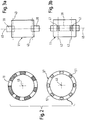
- Fig. 2 shows an annular code carrier 19 having circumferentially magnetized segments.
- the binary code realized thereby can be read by means of a code reader 37, which is ring-shaped according to the code carrier 19 and comprises a plurality of Hall probes 51 arranged distributed in the circumferential direction.
- the code carrier 19 is rotated relative to the code reader 37, which are arranged in the mounted state coaxially with each other and with a small axial distance from each other.
- the essential feature of this positioning device is that due to the use of this single-track Graycode principle adjacent, ie with a rotation of the code reader 19 relative to the code reader 37 consecutive codes only to differ one bit from each other.
- the spatial resolution of the positioning device is determined by the number of magnetization regions of the code carrier 19 and the sensors 51 of the code reader 37.
- Fig. 3a and 3b show two possible variants for performing a multi-level balancing a rotating unit 11, for example, a relatively wide grinding wheel.
- two separate balancing devices 39 are used, which are spaced apart in the axial direction and, for example, each attached to the rotating unit 11.
- a single balancing device 39 may be provided, which has two axially spaced balancing areas 41, wherein at each balancing area 41 at least one balancing mass is arranged. Also in this way can be balanced with a single balancing device 39 at two axially spaced balancing planes 43.
Landscapes
- Physics & Mathematics (AREA)
- General Physics & Mathematics (AREA)
- Testing Of Balance (AREA)
- Constituent Portions Of Griding Lathes, Driving, Sensing And Control (AREA)
Claims (15)
- Dispositif d'équilibrage, en particulier tête d'équilibrage ou anneau d'équilibrage, pour un système d'équilibrage électromécanique pour des unités tournantes (11), en particulier pour des broches de machines-outils, comportant
au moins une masselotte d'équilibrage (13) qui est réglable pour la compensation d'un balourd (U) de l'unité (11),
une unité d'entraînement (15), en particulier un moteur électrique, pour régler la masselotte d'équilibrage (13), et
un moyen de positionnement (17) définissant une pluralité de positions de rotation jusque dans lesquelles la masselotte d'équilibrage (13) est réglable, le moyen de positionnement (17) comprenant un moyen tournant (19, 37) de mesure des positions de rotation, qui tourne avec l'unité (11) pendant le fonctionnement et qui définit ou permet de déterminer la position de rotation absolue de la masselotte d'équilibrage (13) dans un système de coordonnées fixe par rapport au dispositif d'équilibrage,
caractérisé en ce que
le moyen tournant (19, 37) comprend deux composants (19, 37) mobiles en rotation l'un par rapport à l'autre,
un mouvement de rotation de l'un des composants (19) par rapport à l'autre composant (37) est associé à un mouvement de réglage de la masselotte d'équilibrage (13), et
la position de rotation absolue de la masselotte d'équilibrage (13) définit ou permet de déterminer la position relative des deux composants (19, 37). - Dispositif d'équilibrage selon la revendication 1,
caractérisé en ce que
le dispositif d'équilibrage est intégrable dans l'unité (11), est susceptible d'être rapporté sur l'unité (11) et/ou d'être monté autour de l'unité (11). - Dispositif d'équilibrage selon la revendication 1 ou 2,
caractérisé en ce que
pour les positions de rotation, l'effet d'équilibrage (W) respectif de la masselotte d'équilibrage (13) située dans la position de rotation correspondante, et/ou pour chaque modification de la position de rotation de la masselotte d'équilibrage (13), la modification de l'effet d'équilibrage (W) de la masselotte d'équilibrage (13) qui en résulte est connu(e) ou peut être déterminé(e). - Dispositif d'équilibrage selon l'une des revendications précédentes,
caractérisé en ce que
les positions de rotation sont codées et sont lisibles à l'aide d'un lecteur de code (37), et/ou
les positions de rotation sont codées selon le principe du code de Gray, en particulier selon le principe du code de Gray dit Single-Track. - Dispositif d'équilibrage selon la revendication 4,
caractérisé en ce que
un mouvement d'un support de code (19) par rapport à un lecteur de code (37) est associé à un mouvement de réglage de la masselotte d'équilibrage (13), qui a pour conséquence une modification du code lisible de la position de rotation, et en particulier le support de code (19) présente au moins une, de préférence précisément une piste de code annulaire. - Dispositif d'équilibrage selon l'une des revendications précédentes,
caractérisé en ce que
le dispositif d'équilibrage comprend une pluralité de masselottes d'équilibrage (13), en particulier précisément deux masselottes d'équilibrage (13), les masselottes d'équilibrage (13) étant réglables indépendamment l'une de l'autre. - Dispositif d'équilibrage selon l'une des revendications précédentes,
caractérisé en ce que
pour réaliser un équilibrage sur plusieurs plans, le dispositif d'équilibrage comprend au moins deux ensembles d'au moins une masselotte d'équilibrage respective (13) agencés à des emplacements espacés l'un de l'autre le long d'un axe du dispositif d'équilibrage. - Dispositif d'équilibrage selon l'une des revendications précédentes,
caractérisé en ce que
il est prévu un moyen de processus (21) intégré dans le dispositif d'équilibrage et réalisé au moins pour exécuter une partie au moins d'un processus d'équilibrage ayant recours au dispositif d'équilibrage, en fonction de signaux et/ou de données concernant un balourd mesuré (U), et en particulier le moyen de processus (21) est en supplément réalisé pour acquérir des données et/ou des signaux, pour les traiter et/ou pour les mémoriser et/ou pour exécuter des processus qui ne concernent pas le processus d'équilibrage. - Dispositif d'équilibrage, en particulier tête d'équilibrage ou anneau d'équilibrage, pour un système d'équilibrage électromécanique pour des unités tournantes (11), en particulier pour des broches de machines-outils, comportant
au moins une masselotte d'équilibrage (13) qui est réglable pour la compensation d'un balourd (U) de l'unité (11),
une unité d'entraînement (15), en particulier un moteur électrique, pour régler la masselotte d'équilibrage (13), et
un moyen de positionnement (17) définissant une pluralité de positions de rotation jusque dans lesquelles la masselotte d'équilibrage (13) est réglable, le moyen de positionnement (17) comprenant un moyen (19, 37) de mesure des positions de rotation, qui tourne avec l'unité (11) pendant le fonctionnement et qui définit ou permet de déterminer la position de rotation absolue de la masselotte d'équilibrage (13) dans un système de coordonnées fixe par rapport au dispositif d'équilibrage,
caractérisé en ce que
le moyen de mesure des positions de rotation comprend un aimant permanant et un capteur, l'aimant permanent étant agencé de façon mobile en rotation par rapport au capteur et le capteur étant apte à mesurer la position de rotation de l'aiment permanant, en particulier avec une résolution nettement inférieure à 1°,
un mouvement de rotation de l'aimant permanent par rapport au capteur est associé à un mouvement de réglage de la masselotte d'équilibrage (13), et la position de rotation absolue de la masselotte d'équilibrage (13) est définie ou peut être déterminée par la position relative de l'aimant permanent par rapport au capteur. - Système d'équilibrage électromécanique pour des unités tournantes (11), en particulier pour des broches de machines-outils, comportant un dispositif d'équilibrage, intégrable dans une unité (11), rapporté sur une unité (11) et/ou monté autour d'une unité (11), selon l'une des revendications précédentes, et
un moyen de mesure (23) pour déterminer un balourd de l'unité (11), et pour commander un processus d'équilibrage du dispositif d'équilibrage et/ou pour communiquer avec un moyen de processus (21) intégré dans le dispositif d'équilibrage, il est prévu un moyen de commande externe (25). - Système d'équilibrage selon la revendication 10,
caractérisé en ce que
pour alimenter en énergie le dispositif d'équilibrage et/ou pour communiquer entre un moyen de commande externe (25) et un moyen de processus (21) intégré dans le dispositif d'équilibrage, il est prévu un moyen de transmission (27) fonctionnant sans contact physique, et/ou en ce qu'un moyen de commande externe (25) et/ou un moyen de processus (21) intégré dans le dispositif d'équilibrage est réalisé pour calculer automatiquement une position de rotation de consigne pour la masselotte d'équilibrage (13) à partir d'un balourd mesuré (U) de l'unité (11), position dans laquelle la masselotte d'équilibrage (13) compense le balourd (U), et pour régler la masselotte d'équilibrage (13) jusque dans la position de rotation de consigne. - Système d'équilibrage selon la revendication 10 ou 11,
caractérisé en ce que
pour réaliser un équilibrage sur plusieurs plans, il est prévu une pluralité de dispositifs d'équilibrage qui sont réalisés pour être agencés à des emplacements espacés les uns des autres le long de l'axe de rotation de l'unité (11). - Unité (1) tournant pendant le fonctionnement, en particulier broche d'une machine-outil, comportant au moins un dispositif d'équilibrage selon l'une des revendications 1 à 9 ou comportant un système d'équilibrage selon l'une des revendications 10 à 12, et/ou
machine-outil comportant au moins un dispositif d'équilibrage selon l'une des revendications 1 à 9 ou comportant un système d'équilibrage selon l'une des revendications 10 à 12. - Procédé d'équilibrage en particulier automatique d'unités tournantes (11), en particulier de broches de machines-outils, à l'aide d'au moins un dispositif d'équilibrage intégrable dans l'unité (11), rapporté sur l'unité (11) et/ou monté autour de l'unité (11), selon l'une des revendications 1 à 9, dans lequel
un balourd (U) de l'unité (11) est mesuré,
à partir du balourd mesuré (U), une position de rotation de consigne pour la masselotte d'équilibrage (13) est calculée, dans laquelle la masselotte d'équilibrage (13) compense le balourd (U),
la masselotte d'équilibrage (13) est réglée jusque dans la position de rotation de consigne, et
la position de rotation absolue respective de la masselotte d'équilibrage (13) est définie ou peut être déterminée dans un système de coordonnées fixe par rapport au dispositif d'équilibrage. - Procédé selon la revendication 14,
caractérisé en ce que
le procédé, y compris le réglage de la masselotte d'équilibrage (13), est mis en oeuvre lorsque l'unité (11) tourne en particulier à une vitesse de rotation de fonctionnement, et/ou
pour réaliser un équilibrage sur plusieurs plans, le procédé est mis en oeuvre à l'aide d'au moins deux dispositifs d'équilibrage agencés à des emplacements espacés l'un de l'autre le long de l'axe de rotation de l'unité (11) ou à l'aide d'ensembles d'au moins une masselotte d'équilibrage respective (13) intégrés dans un dispositif d'équilibrage.
Applications Claiming Priority (2)
| Application Number | Priority Date | Filing Date | Title |
|---|---|---|---|
| DE200810028892 DE102008028892A1 (de) | 2008-06-18 | 2008-06-18 | Wuchteinrichtung, Auswuchtsystem und Auswuchtverfahren |
| PCT/EP2009/004398 WO2009156094A1 (fr) | 2008-06-18 | 2009-06-18 | Dispositif d'équilibrage, système d'équilibrage et procédé d'équilibrage |
Publications (2)
| Publication Number | Publication Date |
|---|---|
| EP2297563A1 EP2297563A1 (fr) | 2011-03-23 |
| EP2297563B1 true EP2297563B1 (fr) | 2018-09-26 |
Family
ID=41057315
Family Applications (1)
| Application Number | Title | Priority Date | Filing Date |
|---|---|---|---|
| EP09768943.4A Active EP2297563B1 (fr) | 2008-06-18 | 2009-06-18 | Dispositif d'équilibrage, système d'équilibrage et procédé d'équilibrage |
Country Status (4)
| Country | Link |
|---|---|
| EP (1) | EP2297563B1 (fr) |
| DE (1) | DE102008028892A1 (fr) |
| ES (1) | ES2703275T3 (fr) |
| WO (1) | WO2009156094A1 (fr) |
Families Citing this family (6)
| Publication number | Priority date | Publication date | Assignee | Title |
|---|---|---|---|---|
| WO2011140016A1 (fr) * | 2010-05-03 | 2011-11-10 | Lord Corporation | Système d'ordinateur et produit programme d'ordinateur pour équilibrer des machines tournantes |
| ES2798101T3 (es) * | 2012-10-02 | 2020-12-09 | Balance Systems Srl | Procedimiento y dispositivo de balanceo para un cuerpo rotatorio |
| CN103115724B (zh) * | 2013-01-29 | 2015-05-20 | 深圳大学 | 一种高速电主轴的在线动平衡补偿装置及其补偿方法 |
| DE102015223061A1 (de) | 2015-11-23 | 2017-05-24 | Dr. Johannes Heidenhain Gesellschaft Mit Beschränkter Haftung | Winkelmesseinrichtung und Verfahren zum Betreiben einer Winkelmesseinrichtung |
| DE102017117059B4 (de) * | 2017-07-26 | 2026-05-07 | Franz Haimer Maschinenbau Kg | Werkzeugmaschinensystem mit automatischer wuchtprotokollverwertung |
| JP7525629B2 (ja) * | 2020-09-30 | 2024-07-30 | ファナック株式会社 | 工作機械 |
Citations (4)
| Publication number | Priority date | Publication date | Assignee | Title |
|---|---|---|---|---|
| DE2345664A1 (de) | 1973-09-11 | 1975-07-24 | Szerszamgepipari Muevek | Auswuchtvorrichtung mit zwei oder mehreren auswuchtebenen zum dynamischen auswuchten von maschinenteilen, insbesondere breiten schleifkoerpern waehrend ihres umlaufes |
| EP0409050A2 (fr) | 1989-07-20 | 1991-01-23 | BALANCE SYSTEMS S.r.l. | Dispositif d'équilibrage dynamique d'une masse en rotation, en particulier pour meules de rectification |
| WO1996017294A1 (fr) | 1994-11-29 | 1996-06-06 | Balance Dynamics Corporation | Compensateur rotatif de desequilibre de machine a commande electromagnetique |
| EP1870198A1 (fr) | 2006-06-23 | 2007-12-26 | Marposs Societa' Per Azioni | Système de commande et dispositif d'équilibrage d'une machine-outil avec outils rotatifs |
Family Cites Families (16)
| Publication number | Priority date | Publication date | Assignee | Title |
|---|---|---|---|---|
| DE3720746A1 (de) * | 1987-06-23 | 1989-01-05 | Dittel Walter Gmbh | Auswuchtvorrichtung fuer von einer umlaufenden welle getragene gegenstaende |
| DE3742149A1 (de) * | 1987-12-09 | 1989-06-22 | Studio S Ges Fuer Elektronik D | Verfahren und vorrichtung zum ausgleich der unwucht von rotationskoerpern |
| DE4215723A1 (de) * | 1992-05-13 | 1993-11-18 | Dittel Walter Gmbh | Verfahren zum Steuern einer Schleifmaschine |
| DE4222535A1 (de) * | 1992-07-09 | 1994-01-13 | Hofmann Werkstatt Technik | Vorrichtung zum Umwuchtausgleich einer um eine Rotationsachse drehbaren Schleifscheibe |
| IT1258192B (it) * | 1992-08-03 | 1996-02-21 | Marposs Spa | Dispositivo di equilibratura dinamica di un corpo rotante |
| GB9218068D0 (en) * | 1992-08-25 | 1992-10-14 | Euroflex Transmissions Ltd | Automatic balancing system |
| IT1263065B (it) * | 1993-03-22 | 1996-07-24 | Marposs Spa | Apparecchio per l'equilibratura dinamica di un corpo rotante. |
| US6606922B2 (en) * | 2000-04-28 | 2003-08-19 | Schmitt Measurement Systems, Inc. | Rotational imbalance compensator |
| WO2001098745A1 (fr) * | 2000-06-19 | 2001-12-27 | Ultra Electronics Limited | Dispositif d'equilibrage adaptatif pour masse tournante |
| US7267029B2 (en) * | 2001-11-14 | 2007-09-11 | Lord Corporation | Balancing device for a rotating member and associated methods |
| DE10244857A1 (de) * | 2002-09-26 | 2004-04-08 | GFE-Gesellschaft für Fertigungstechnik und Entwicklung Schmalkalden/Chemnitz mbH | Mechatronisches Wuchtmodul für rotierende Werkzeuge |
| DE10304719B4 (de) * | 2003-02-06 | 2005-12-01 | Ifa-Technologies Gmbh | Auswuchteinrichtung für eine einen Hohlraum aufweisende hochzylindrische Kraftfahrzeugantriebswelle und Verfahren zum Betreiben derselben |
| DE102004004299B4 (de) * | 2004-01-28 | 2012-04-05 | Siemens Ag | Bildgebendes Tomographie-Gerät mit Auswuchtvorrichtung |
| DE102004014992A1 (de) * | 2004-03-26 | 2005-10-13 | Hofmann Mess- Und Auswuchttechnik Gmbh & Co. Kg | Auswuchtvorrichtung zur Kompensation der Unwucht von Rotoren von Windkraftanlagen |
| WO2006017201A1 (fr) * | 2004-07-12 | 2006-02-16 | Lord Corporation | Machine tournante à compensateur actif et procédé d’équilibrage dynamique d’un arbre de machine tournante avec vibrations de torsion |
| DE102005018369A1 (de) * | 2005-03-30 | 2006-10-05 | Hofmann Mess- Und Auswuchttechnik Gmbh & Co. Kg | Drehanoden-Röntgenröhre |
-
2008
- 2008-06-18 DE DE200810028892 patent/DE102008028892A1/de not_active Ceased
-
2009
- 2009-06-18 WO PCT/EP2009/004398 patent/WO2009156094A1/fr not_active Ceased
- 2009-06-18 EP EP09768943.4A patent/EP2297563B1/fr active Active
- 2009-06-18 ES ES09768943T patent/ES2703275T3/es active Active
Patent Citations (4)
| Publication number | Priority date | Publication date | Assignee | Title |
|---|---|---|---|---|
| DE2345664A1 (de) | 1973-09-11 | 1975-07-24 | Szerszamgepipari Muevek | Auswuchtvorrichtung mit zwei oder mehreren auswuchtebenen zum dynamischen auswuchten von maschinenteilen, insbesondere breiten schleifkoerpern waehrend ihres umlaufes |
| EP0409050A2 (fr) | 1989-07-20 | 1991-01-23 | BALANCE SYSTEMS S.r.l. | Dispositif d'équilibrage dynamique d'une masse en rotation, en particulier pour meules de rectification |
| WO1996017294A1 (fr) | 1994-11-29 | 1996-06-06 | Balance Dynamics Corporation | Compensateur rotatif de desequilibre de machine a commande electromagnetique |
| EP1870198A1 (fr) | 2006-06-23 | 2007-12-26 | Marposs Societa' Per Azioni | Système de commande et dispositif d'équilibrage d'une machine-outil avec outils rotatifs |
Non-Patent Citations (3)
| Title |
|---|
| "Gray Code", WIKIPEDIA, 12 June 2008 (2008-06-12), pages 1 - 10, XP055618275 |
| ANONYMOUS: "Hall effect sensor", WIKIPEDIA, 19 May 2008 (2008-05-19), pages 1 - 2, XP055618286 |
| ANONYMOUS: "Rotary Encoder", WIKIPEDIA, 13 June 2008 (2008-06-13), XP055618288 |
Also Published As
| Publication number | Publication date |
|---|---|
| WO2009156094A1 (fr) | 2009-12-30 |
| DE102008028892A1 (de) | 2009-12-31 |
| EP2297563A1 (fr) | 2011-03-23 |
| ES2703275T3 (es) | 2019-03-07 |
Similar Documents
| Publication | Publication Date | Title |
|---|---|---|
| EP2297563B1 (fr) | Dispositif d'équilibrage, système d'équilibrage et procédé d'équilibrage | |
| DE102006035164B4 (de) | Werkzeugmaschine mit verbessertem Rundlauf | |
| EP3766646A1 (fr) | Train d'engrenage de type roue cycloïdale pourvu de dispositif de détection de couple | |
| EP1955796B1 (fr) | Broche de machine comprenant un dispositif de serrage | |
| DE102008000489B3 (de) | Verfahren und Vorrichtung zur Reparatur eines Schleifringes im eingebauten Zustand | |
| EP3584559A1 (fr) | Procédé de pronostic d'usure et de maintenance pour une machine de travail de sols | |
| DE102019100211B4 (de) | Parallelglied-Roboter | |
| DE2758275C2 (de) | Verfahren bzw. Einrichtung zum Außenrund- und Planschleifen | |
| DE10013277A1 (de) | Spindelvorrichtung und Werkzeugmaschine zur Verwendung einer solchen | |
| EP0252164A1 (fr) | Méthode et dispositif pour déterminer la position radiale d'un profil neuf obtenu par fraisage | |
| DE102015103670B4 (de) | Verfahren und Vorrichtung zum Ausgleich einer Unwucht eines Rotors | |
| DE10351347A1 (de) | Meß- und Überwachungseinrichtung für Bearbeitungsmaschinen | |
| DE102006036051A1 (de) | Rundtischlagerungs- und Antriebsvorrichtung | |
| EP4252962B1 (fr) | Dispositif et procédé de détection de l'approche d'un outil sur une pièce | |
| WO2014082634A2 (fr) | Dispositif de réception d'une pièce pour un système rotatif de porte-pièce appartenant à une machine de production | |
| WO2019020164A1 (fr) | Outil électrique et procédé pour repérer un événement de rebond d'un outil électrique | |
| DE102005016346B3 (de) | Diskenmeißel-Verschleißmessvorrichtung und Verfahren zur Messung eines Diskenmeißelverschleißes | |
| EP2098929B1 (fr) | Procédé de fonctionnement pour une machine entraînée à l'aide d'un entraînement électrique dotée d'une reconnaissance d'état par l'intermédiaire de l'analyse de fréquence | |
| EP2894448B1 (fr) | Dispositif de détection de l'état d'un élément de machine | |
| WO2009156095A1 (fr) | Dispositif d'équilibrage, système d'équilibrage et procédé d'équilibrage | |
| DE2113690C3 (de) | Vorrichtung zur Übertragung von Meßwerten aus oder von Steuerimpulsen in Maschinen bzw. Einrichtungen mit relativ zueinander rotierenden Teilen | |
| EP2019291B1 (fr) | Corps doté d'une mise à l'échelle d'angle et son utilisation | |
| WO2018157184A1 (fr) | Robot à bras articulé et procédé d'usinage par enlèvement de copeaux d'une pièce au moyen du robot à bras articulé | |
| DE10153915A1 (de) | Verfahren und Vorrichtung zur Fassung der Ist-Stellung eines zu lenkenden Rades bei einem Flurförderzeug mit einer elektrischen Lenkung | |
| AT523205B1 (de) | Roboter-Bearbeitungskopf sowie Verfahren zur Bearbeitung eines Werkstücks mit einem Bearbeitungskopf |
Legal Events
| Date | Code | Title | Description |
|---|---|---|---|
| PUAI | Public reference made under article 153(3) epc to a published international application that has entered the european phase |
Free format text: ORIGINAL CODE: 0009012 |
|
| 17P | Request for examination filed |
Effective date: 20110117 |
|
| AK | Designated contracting states |
Kind code of ref document: A1 Designated state(s): AT BE BG CH CY CZ DE DK EE ES FI FR GB GR HR HU IE IS IT LI LT LU LV MC MK MT NL NO PL PT RO SE SI SK TR |
|
| AX | Request for extension of the european patent |
Extension state: AL BA RS |
|
| DAX | Request for extension of the european patent (deleted) | ||
| STAA | Information on the status of an ep patent application or granted ep patent |
Free format text: STATUS: EXAMINATION IS IN PROGRESS |
|
| 17Q | First examination report despatched |
Effective date: 20170220 |
|
| GRAP | Despatch of communication of intention to grant a patent |
Free format text: ORIGINAL CODE: EPIDOSNIGR1 |
|
| STAA | Information on the status of an ep patent application or granted ep patent |
Free format text: STATUS: GRANT OF PATENT IS INTENDED |
|
| INTG | Intention to grant announced |
Effective date: 20180212 |
|
| GRAJ | Information related to disapproval of communication of intention to grant by the applicant or resumption of examination proceedings by the epo deleted |
Free format text: ORIGINAL CODE: EPIDOSDIGR1 |
|
| STAA | Information on the status of an ep patent application or granted ep patent |
Free format text: STATUS: EXAMINATION IS IN PROGRESS |
|
| GRAJ | Information related to disapproval of communication of intention to grant by the applicant or resumption of examination proceedings by the epo deleted |
Free format text: ORIGINAL CODE: EPIDOSDIGR1 |
|
| GRAP | Despatch of communication of intention to grant a patent |
Free format text: ORIGINAL CODE: EPIDOSNIGR1 |
|
| GRAP | Despatch of communication of intention to grant a patent |
Free format text: ORIGINAL CODE: EPIDOSNIGR1 |
|
| INTC | Intention to grant announced (deleted) | ||
| STAA | Information on the status of an ep patent application or granted ep patent |
Free format text: STATUS: GRANT OF PATENT IS INTENDED |
|
| INTG | Intention to grant announced |
Effective date: 20180517 |
|
| GRAS | Grant fee paid |
Free format text: ORIGINAL CODE: EPIDOSNIGR3 |
|
| GRAA | (expected) grant |
Free format text: ORIGINAL CODE: 0009210 |
|
| STAA | Information on the status of an ep patent application or granted ep patent |
Free format text: STATUS: THE PATENT HAS BEEN GRANTED |
|
| AK | Designated contracting states |
Kind code of ref document: B1 Designated state(s): AT BE BG CH CY CZ DE DK EE ES FI FR GB GR HR HU IE IS IT LI LT LU LV MC MK MT NL NO PL PT RO SE SI SK TR |
|
| REG | Reference to a national code |
Ref country code: GB Ref legal event code: FG4D Free format text: NOT ENGLISH |
|
| REG | Reference to a national code |
Ref country code: CH Ref legal event code: EP |
|
| REG | Reference to a national code |
Ref country code: CH Ref legal event code: NV Representative=s name: INTELLECTUAL PROPERTY SERVICES GMBH, CH Ref country code: AT Ref legal event code: REF Ref document number: 1046584 Country of ref document: AT Kind code of ref document: T Effective date: 20181015 |
|
| REG | Reference to a national code |
Ref country code: IE Ref legal event code: FG4D Free format text: LANGUAGE OF EP DOCUMENT: GERMAN |
|
| REG | Reference to a national code |
Ref country code: DE Ref legal event code: R096 Ref document number: 502009015322 Country of ref document: DE |
|
| REG | Reference to a national code |
Ref country code: SE Ref legal event code: TRGR |
|
| REG | Reference to a national code |
Ref country code: NL Ref legal event code: MP Effective date: 20180926 |
|
| PG25 | Lapsed in a contracting state [announced via postgrant information from national office to epo] |
Ref country code: BG Free format text: LAPSE BECAUSE OF FAILURE TO SUBMIT A TRANSLATION OF THE DESCRIPTION OR TO PAY THE FEE WITHIN THE PRESCRIBED TIME-LIMIT Effective date: 20181226 Ref country code: LT Free format text: LAPSE BECAUSE OF FAILURE TO SUBMIT A TRANSLATION OF THE DESCRIPTION OR TO PAY THE FEE WITHIN THE PRESCRIBED TIME-LIMIT Effective date: 20180926 Ref country code: NO Free format text: LAPSE BECAUSE OF FAILURE TO SUBMIT A TRANSLATION OF THE DESCRIPTION OR TO PAY THE FEE WITHIN THE PRESCRIBED TIME-LIMIT Effective date: 20181226 Ref country code: GR Free format text: LAPSE BECAUSE OF FAILURE TO SUBMIT A TRANSLATION OF THE DESCRIPTION OR TO PAY THE FEE WITHIN THE PRESCRIBED TIME-LIMIT Effective date: 20181227 Ref country code: FI Free format text: LAPSE BECAUSE OF FAILURE TO SUBMIT A TRANSLATION OF THE DESCRIPTION OR TO PAY THE FEE WITHIN THE PRESCRIBED TIME-LIMIT Effective date: 20180926 |
|
| REG | Reference to a national code |
Ref country code: LT Ref legal event code: MG4D |
|
| PG25 | Lapsed in a contracting state [announced via postgrant information from national office to epo] |
Ref country code: HR Free format text: LAPSE BECAUSE OF FAILURE TO SUBMIT A TRANSLATION OF THE DESCRIPTION OR TO PAY THE FEE WITHIN THE PRESCRIBED TIME-LIMIT Effective date: 20180926 Ref country code: LV Free format text: LAPSE BECAUSE OF FAILURE TO SUBMIT A TRANSLATION OF THE DESCRIPTION OR TO PAY THE FEE WITHIN THE PRESCRIBED TIME-LIMIT Effective date: 20180926 |
|
| REG | Reference to a national code |
Ref country code: ES Ref legal event code: FG2A Ref document number: 2703275 Country of ref document: ES Kind code of ref document: T3 Effective date: 20190307 |
|
| PG25 | Lapsed in a contracting state [announced via postgrant information from national office to epo] |
Ref country code: RO Free format text: LAPSE BECAUSE OF FAILURE TO SUBMIT A TRANSLATION OF THE DESCRIPTION OR TO PAY THE FEE WITHIN THE PRESCRIBED TIME-LIMIT Effective date: 20180926 Ref country code: EE Free format text: LAPSE BECAUSE OF FAILURE TO SUBMIT A TRANSLATION OF THE DESCRIPTION OR TO PAY THE FEE WITHIN THE PRESCRIBED TIME-LIMIT Effective date: 20180926 Ref country code: IS Free format text: LAPSE BECAUSE OF FAILURE TO SUBMIT A TRANSLATION OF THE DESCRIPTION OR TO PAY THE FEE WITHIN THE PRESCRIBED TIME-LIMIT Effective date: 20190126 Ref country code: NL Free format text: LAPSE BECAUSE OF FAILURE TO SUBMIT A TRANSLATION OF THE DESCRIPTION OR TO PAY THE FEE WITHIN THE PRESCRIBED TIME-LIMIT Effective date: 20180926 Ref country code: PL Free format text: LAPSE BECAUSE OF FAILURE TO SUBMIT A TRANSLATION OF THE DESCRIPTION OR TO PAY THE FEE WITHIN THE PRESCRIBED TIME-LIMIT Effective date: 20180926 |
|
| PG25 | Lapsed in a contracting state [announced via postgrant information from national office to epo] |
Ref country code: PT Free format text: LAPSE BECAUSE OF FAILURE TO SUBMIT A TRANSLATION OF THE DESCRIPTION OR TO PAY THE FEE WITHIN THE PRESCRIBED TIME-LIMIT Effective date: 20190126 Ref country code: SK Free format text: LAPSE BECAUSE OF FAILURE TO SUBMIT A TRANSLATION OF THE DESCRIPTION OR TO PAY THE FEE WITHIN THE PRESCRIBED TIME-LIMIT Effective date: 20180926 |
|
| REG | Reference to a national code |
Ref country code: DE Ref legal event code: R026 Ref document number: 502009015322 Country of ref document: DE |
|
| PLAZ | Examination of admissibility of opposition: despatch of communication + time limit |
Free format text: ORIGINAL CODE: EPIDOSNOPE2 |
|
| PLBI | Opposition filed |
Free format text: ORIGINAL CODE: 0009260 |
|
| PLBA | Examination of admissibility of opposition: reply received |
Free format text: ORIGINAL CODE: EPIDOSNOPE4 |
|
| 26 | Opposition filed |
Opponent name: BALANCE SYSTEMS S.R.L. Effective date: 20190625 |
|
| PG25 | Lapsed in a contracting state [announced via postgrant information from national office to epo] |
Ref country code: DK Free format text: LAPSE BECAUSE OF FAILURE TO SUBMIT A TRANSLATION OF THE DESCRIPTION OR TO PAY THE FEE WITHIN THE PRESCRIBED TIME-LIMIT Effective date: 20180926 |
|
| PLAX | Notice of opposition and request to file observation + time limit sent |
Free format text: ORIGINAL CODE: EPIDOSNOBS2 |
|
| PG25 | Lapsed in a contracting state [announced via postgrant information from national office to epo] |
Ref country code: SI Free format text: LAPSE BECAUSE OF FAILURE TO SUBMIT A TRANSLATION OF THE DESCRIPTION OR TO PAY THE FEE WITHIN THE PRESCRIBED TIME-LIMIT Effective date: 20180926 |
|
| PLBB | Reply of patent proprietor to notice(s) of opposition received |
Free format text: ORIGINAL CODE: EPIDOSNOBS3 |
|
| PG25 | Lapsed in a contracting state [announced via postgrant information from national office to epo] |
Ref country code: MC Free format text: LAPSE BECAUSE OF FAILURE TO SUBMIT A TRANSLATION OF THE DESCRIPTION OR TO PAY THE FEE WITHIN THE PRESCRIBED TIME-LIMIT Effective date: 20180926 |
|
| REG | Reference to a national code |
Ref country code: BE Ref legal event code: MM Effective date: 20190630 |
|
| PG25 | Lapsed in a contracting state [announced via postgrant information from national office to epo] |
Ref country code: TR Free format text: LAPSE BECAUSE OF FAILURE TO SUBMIT A TRANSLATION OF THE DESCRIPTION OR TO PAY THE FEE WITHIN THE PRESCRIBED TIME-LIMIT Effective date: 20180926 |
|
| PG25 | Lapsed in a contracting state [announced via postgrant information from national office to epo] |
Ref country code: IE Free format text: LAPSE BECAUSE OF NON-PAYMENT OF DUE FEES Effective date: 20190618 |
|
| PG25 | Lapsed in a contracting state [announced via postgrant information from national office to epo] |
Ref country code: BE Free format text: LAPSE BECAUSE OF NON-PAYMENT OF DUE FEES Effective date: 20190630 Ref country code: LU Free format text: LAPSE BECAUSE OF NON-PAYMENT OF DUE FEES Effective date: 20190618 |
|
| PG25 | Lapsed in a contracting state [announced via postgrant information from national office to epo] |
Ref country code: CY Free format text: LAPSE BECAUSE OF FAILURE TO SUBMIT A TRANSLATION OF THE DESCRIPTION OR TO PAY THE FEE WITHIN THE PRESCRIBED TIME-LIMIT Effective date: 20180926 |
|
| PG25 | Lapsed in a contracting state [announced via postgrant information from national office to epo] |
Ref country code: MT Free format text: LAPSE BECAUSE OF FAILURE TO SUBMIT A TRANSLATION OF THE DESCRIPTION OR TO PAY THE FEE WITHIN THE PRESCRIBED TIME-LIMIT Effective date: 20180926 Ref country code: HU Free format text: LAPSE BECAUSE OF FAILURE TO SUBMIT A TRANSLATION OF THE DESCRIPTION OR TO PAY THE FEE WITHIN THE PRESCRIBED TIME-LIMIT; INVALID AB INITIO Effective date: 20090618 |
|
| PLCK | Communication despatched that opposition was rejected |
Free format text: ORIGINAL CODE: EPIDOSNREJ1 |
|
| APAH | Appeal reference modified |
Free format text: ORIGINAL CODE: EPIDOSCREFNO |
|
| APBM | Appeal reference recorded |
Free format text: ORIGINAL CODE: EPIDOSNREFNO |
|
| APBP | Date of receipt of notice of appeal recorded |
Free format text: ORIGINAL CODE: EPIDOSNNOA2O |
|
| APBQ | Date of receipt of statement of grounds of appeal recorded |
Free format text: ORIGINAL CODE: EPIDOSNNOA3O |
|
| PG25 | Lapsed in a contracting state [announced via postgrant information from national office to epo] |
Ref country code: MK Free format text: LAPSE BECAUSE OF FAILURE TO SUBMIT A TRANSLATION OF THE DESCRIPTION OR TO PAY THE FEE WITHIN THE PRESCRIBED TIME-LIMIT Effective date: 20180926 |
|
| P01 | Opt-out of the competence of the unified patent court (upc) registered |
Effective date: 20230601 |
|
| REG | Reference to a national code |
Ref country code: DE Ref legal event code: R100 Ref document number: 502009015322 Country of ref document: DE |
|
| APBU | Appeal procedure closed |
Free format text: ORIGINAL CODE: EPIDOSNNOA9O |
|
| PLBN | Opposition rejected |
Free format text: ORIGINAL CODE: 0009273 |
|
| STAA | Information on the status of an ep patent application or granted ep patent |
Free format text: STATUS: OPPOSITION REJECTED |
|
| PGFP | Annual fee paid to national office [announced via postgrant information from national office to epo] |
Ref country code: AT Payment date: 20240620 Year of fee payment: 16 |
|
| PGFP | Annual fee paid to national office [announced via postgrant information from national office to epo] |
Ref country code: FR Payment date: 20240628 Year of fee payment: 16 |
|
| 27O | Opposition rejected |
Effective date: 20240626 |
|
| PGFP | Annual fee paid to national office [announced via postgrant information from national office to epo] |
Ref country code: SE Payment date: 20240619 Year of fee payment: 16 |
|
| PGFP | Annual fee paid to national office [announced via postgrant information from national office to epo] |
Ref country code: GB Payment date: 20250627 Year of fee payment: 17 |
|
| PGFP | Annual fee paid to national office [announced via postgrant information from national office to epo] |
Ref country code: CZ Payment date: 20250626 Year of fee payment: 17 |
|
| PGFP | Annual fee paid to national office [announced via postgrant information from national office to epo] |
Ref country code: ES Payment date: 20250728 Year of fee payment: 17 |
|
| PGFP | Annual fee paid to national office [announced via postgrant information from national office to epo] |
Ref country code: DE Payment date: 20250827 Year of fee payment: 17 |
|
| PGFP | Annual fee paid to national office [announced via postgrant information from national office to epo] |
Ref country code: IT Payment date: 20250627 Year of fee payment: 17 |
|
| PGFP | Annual fee paid to national office [announced via postgrant information from national office to epo] |
Ref country code: CH Payment date: 20250707 Year of fee payment: 17 |
|
| REG | Reference to a national code |
Ref country code: SE Ref legal event code: EUG |
|
| REG | Reference to a national code |
Ref country code: AT Ref legal event code: MM01 Ref document number: 1046584 Country of ref document: AT Kind code of ref document: T Effective date: 20250618 |
|
| PG25 | Lapsed in a contracting state [announced via postgrant information from national office to epo] |
Ref country code: AT Free format text: LAPSE BECAUSE OF NON-PAYMENT OF DUE FEES Effective date: 20250618 |
|
| PG25 | Lapsed in a contracting state [announced via postgrant information from national office to epo] |
Ref country code: FR Free format text: LAPSE BECAUSE OF NON-PAYMENT OF DUE FEES Effective date: 20250630 |