EP2297820B1 - Dispositif métallique de connexion d un conducteur de protection - Google Patents
Dispositif métallique de connexion d un conducteur de protection Download PDFInfo
- Publication number
- EP2297820B1 EP2297820B1 EP09769111.7A EP09769111A EP2297820B1 EP 2297820 B1 EP2297820 B1 EP 2297820B1 EP 09769111 A EP09769111 A EP 09769111A EP 2297820 B1 EP2297820 B1 EP 2297820B1
- Authority
- EP
- European Patent Office
- Prior art keywords
- spring
- contact
- connection device
- segment
- conductor connection
- Prior art date
- Legal status (The legal status is an assumption and is not a legal conclusion. Google has not performed a legal analysis and makes no representation as to the accuracy of the status listed.)
- Not-in-force
Links
Images


Classifications
-
- H—ELECTRICITY
- H01—ELECTRIC ELEMENTS
- H01R—ELECTRICALLY-CONDUCTIVE CONNECTIONS; STRUCTURAL ASSOCIATIONS OF A PLURALITY OF MUTUALLY-INSULATED ELECTRICAL CONNECTING ELEMENTS; COUPLING DEVICES; CURRENT COLLECTORS
- H01R9/00—Structural associations of a plurality of mutually-insulated electrical connecting elements, e.g. terminal strips or terminal blocks; Terminals or binding posts mounted upon a base or in a case; Bases therefor
- H01R9/22—Bases, e.g. strip, block, panel
- H01R9/24—Terminal blocks
- H01R9/26—Clip-on terminal blocks for side-by-side rail- or strip-mounting
- H01R9/2691—Clip-on terminal blocks for side-by-side rail- or strip-mounting with ground wire connection to the rail
-
- H—ELECTRICITY
- H01—ELECTRIC ELEMENTS
- H01R—ELECTRICALLY-CONDUCTIVE CONNECTIONS; STRUCTURAL ASSOCIATIONS OF A PLURALITY OF MUTUALLY-INSULATED ELECTRICAL CONNECTING ELEMENTS; COUPLING DEVICES; CURRENT COLLECTORS
- H01R9/00—Structural associations of a plurality of mutually-insulated electrical connecting elements, e.g. terminal strips or terminal blocks; Terminals or binding posts mounted upon a base or in a case; Bases therefor
- H01R9/22—Bases, e.g. strip, block, panel
- H01R9/24—Terminal blocks
- H01R9/26—Clip-on terminal blocks for side-by-side rail- or strip-mounting
- H01R9/2608—Fastening means for mounting on support rail or strip
Definitions
- the invention relates to a protective conductor connection device according to the preamble of claim 1.
- Such protective conductor connection devices are used in different designs, in particular in terminal blocks which can be snapped onto mounting rails or in electronics housings of a different type, for example in control cabinets of machines, in order to produce a connection to the mounting rail.
- the contact resistance should be as low as possible to the support rail and a high current transition can be ensured in case of failure.
- the object of the present invention is to provide an improved protective conductor connection device.
- Another mechanical advantage is that on the one hand there is a higher strength through the U-shaped cross section and on the other hand more material is available for wear.
- the main body is formed in a simple manner producible as a stamped and bent part.
- the contact portion may be part of a contact tab, which is punched out of the material of the body and bent over.
- a still further advantage results from the fact that the contact tab is held positively between sections of the leg portions, whereby the strength of the U-shaped base body is increased.
- the spring is held biased between the leg portions and parts of the base portion of the body, the necessary holding portions are simultaneously produced during punching bending process.
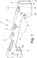
- Fig. 1 shows a perspective view of an embodiment of a protective conductor terminal device 1 according to the invention.
- the protective conductor connection device 1 is preferably a component of an otherwise not shown here terminal block or an electronics housing (functional electronics). It has a conductive base body 2, which has a U-shaped cross-section with a base portion 4, on whose longitudinal sides in each case a first leg 5 and a second leg 6 are bent by 90 °. The legs 5 and 6 have a specific contour, which has a (catch) receptacle 9 or a mounting foot for a mounting rail 16 (see, for example, FIG. Fig. 3 ).
- a spring 11 arranged biased.
- One end portion of the spring is held on a holding portion 7 of the base portion 4 of the main body 2, and another end portion is held as a spring support portion 13 on a support portion 8 of the base portion 4 of the main body 2.
- the spring 11 will be explained in more detail below.
- an opening between two leg portions of the base body 2 is closed by a contact tab 3 having a contact portion 10.
- the main body 2 is formed as a stamped and bent part, wherein the support portion 8 and the contact tab 3 are formed from the base portion 4 of the base body 2 by punching, molding and bending.
- the contact tab 3 is shaped such that it has recesses which coincide with projections of the leg portions in Engage, whereby a strength of the stamped and bent body 2 increases.
- the contact tab 3 is formed from the base portion 4, its contact portion 10 preferably has at least the width of the base portion 4. This enables a line contact portion having a high current transfer capability in cooperation with a support rail 16, as will be shown below.
- Fig. 2 illustrates a side view of the protective conductor terminal device 1 according to the invention Fig. 1
- the spring 11 has an elongated spring end 15, which is held by the holding portion 7 and a folded edge thereof as a stop. In the further course to the right, the spring 11 bends down and merges into a substantially semicircular spring belly 14.
- the spring belly 14 terminates in the spring support portion 13, which is curved opposite to the radius of the spring belly 14 and is supported on the correspondingly shaped support portion 8 of the main body 2. In this case, the spring 11 is arranged taut, wherein its spring contact portion 12 protrudes into the receptacle 9.
- a support rail 16 with a first and second rail legs 17, 18 can be used.
- this is a so-called DIN rail.
- the first rail leg 17 presses against the spring force of the spring contact section 12.
- the second rail leg 18 is pressed against the contact section 10.
- the spring 11 thus produces a Kunststoffanpresskraft.
- Fig. 4 Illustrates the side view Fig. 3 in a partial sectional view, wherein it can be seen that the spring contact portion 12 is in line contact with the width of the spring with an edge of the first rail leg 17.
- the second rail leg 18 is in line contact with the contact portion 10 of the contact tab 3 on. In this case, a contact on the entire rectangular surface of the contact portion 10 with the rectangular surface of the second rail leg 18 is present, which results in a high power transmission cross-section.
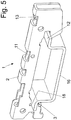
- FIG. 5 a perspective view Fig. 1 respectively.
- the mounting rail can also have a different profile.
- the contact portion 10 is made wider than the base portion 4.
- the spring 11 may be arranged and tensioned in another form.
- Fig. 6 discloses that a conductor connection 19 is formed on the main body (cage) 2.
- a conductor connection plane is formed in a simple manner, which can be formed eg directly on the main body (cage) 2 aöls punching bending contour or in another way, as a soldering, riveting, embossing or welding connection.
- the conductor connection is designed as a busbar 19, which is conductively arranged on the base body 2 or integrally connected thereto.
Landscapes
- Connections Arranged To Contact A Plurality Of Conductors (AREA)
- Coupling Device And Connection With Printed Circuit (AREA)
- Multi-Conductor Connections (AREA)
- Installation Of Bus-Bars (AREA)
Claims (3)
- Composant de connexion (1) pour conducteur de protection fait d'un métal conducteur, en particulier pour une borne série ou un boîtier électronique, avec :un corps (2) qui présente au moins un logement (9) pour recevoir un rail porteur (16) ; etun ressort (11) relié de façon conductrice électrique au corps (2) pour produire une force d'appui en contact,le corps (2) présentant une section en forme de U,caractérisé en ce quele corps (2) présente sur sa longueur la section en forme de U avec la partie de base (4) et les deux parties formant les bras (5, 6),en ce que le corps (2) présente une partie de contact (10) avec une zone de contact linéaire avec le rail porteur, qui est plus large que l'épaisseur du matériau conducteur et/ou qui présente au moins la largeur de la partie de base (4),en ce que le corps (2) est conformé comme une pièce découpée et pliée,en ce que la partie de contact (10) fait partie d'une patte de contact (3) qui est découpée dans le matériau du corps (2) et recourbée et qui est retenue en correspondance de forme entre des parties des parties formant des bras (5, 6), et le ressort (11) est précontraint en tension entre les parties formant les bras (5, 6) et des parties de la partie de base (4) du corps (2).
- Composant de connexion pour conducteur de protection selon la revendication 1, caractérisé en ce qu'une connexion de conducteur (19) est formée sur le corps de base (2).
- Composant de connexion pour conducteur de protection selon la revendication 2, caractérisé en ce que la connexion de conducteur (19) est conformée comme une barre collectrice (19) qui est disposée de façon conductrice sur le corps de base (2) ou qui est reliée d'une pièce à celui-ci.
Priority Applications (1)
| Application Number | Priority Date | Filing Date | Title |
|---|---|---|---|
| SI200931774T SI2297820T1 (en) | 2008-06-27 | 2009-06-08 | Metal connection device of the protective conductor |
Applications Claiming Priority (2)
| Application Number | Priority Date | Filing Date | Title |
|---|---|---|---|
| DE202008008656U DE202008008656U1 (de) | 2008-06-27 | 2008-06-27 | Schutzleiteranschlußvorrichtung aus Metall |
| PCT/EP2009/057018 WO2009156262A1 (fr) | 2008-06-27 | 2009-06-08 | Dispositif métallique de connexion d’un conducteur de protection |
Publications (2)
| Publication Number | Publication Date |
|---|---|
| EP2297820A1 EP2297820A1 (fr) | 2011-03-23 |
| EP2297820B1 true EP2297820B1 (fr) | 2017-10-18 |
Family
ID=40972843
Family Applications (1)
| Application Number | Title | Priority Date | Filing Date |
|---|---|---|---|
| EP09769111.7A Not-in-force EP2297820B1 (fr) | 2008-06-27 | 2009-06-08 | Dispositif métallique de connexion d un conducteur de protection |
Country Status (8)
| Country | Link |
|---|---|
| US (1) | US8231391B2 (fr) |
| EP (1) | EP2297820B1 (fr) |
| CN (1) | CN102077420B (fr) |
| BR (1) | BRPI0914535B1 (fr) |
| DE (1) | DE202008008656U1 (fr) |
| ES (1) | ES2655889T3 (fr) |
| SI (1) | SI2297820T1 (fr) |
| WO (1) | WO2009156262A1 (fr) |
Families Citing this family (6)
| Publication number | Priority date | Publication date | Assignee | Title |
|---|---|---|---|---|
| CN103919615B (zh) * | 2014-04-30 | 2017-01-25 | 迈柯唯医疗设备(苏州)有限公司 | 医用吊塔箱体及用于该医用吊塔箱体的立柱 |
| EP3054531B1 (fr) * | 2015-02-05 | 2018-05-16 | Morsettitalia S.p.A. | Élément conducteur de connexion à terre pour block terminal de tableau electrique et le correspondant block terminal pour câbles de mis à terre |
| EP3391471B1 (fr) * | 2015-12-17 | 2023-03-22 | TE Connectivity Germany GmbH | Prise de rail à transmission de courant améliorée |
| DE102016113809A1 (de) * | 2016-07-27 | 2018-02-01 | DEHN + SÖHNE GmbH + Co. KG. | Befestigungsvorrichtung für ein in einem Gehäuse befindliches elektrisches Bauteil |
| DE202018105269U1 (de) * | 2018-09-14 | 2019-12-17 | Weidmüller Interface GmbH & Co. KG | Stromschiene für einen elektrischen Leiter und Baugruppe mit der Stromschiene |
| TWI717908B (zh) * | 2019-11-20 | 2021-02-01 | 進聯工業股份有限公司 | 用於軌道型端子裝置之導電組件結構 |
Citations (1)
| Publication number | Priority date | Publication date | Assignee | Title |
|---|---|---|---|---|
| DE1880354U (de) * | 1963-01-10 | 1963-10-10 | Busch Jaeger Duerener Metall | Befestigung eines elektrischen installationsgeraetes auf einer tragschiene. |
Family Cites Families (14)
| Publication number | Priority date | Publication date | Assignee | Title |
|---|---|---|---|---|
| DE2352432B2 (de) * | 1973-10-19 | 1979-06-21 | Fa. Georg Schlegel, 7941 Duermentingen | Schaltanlagen-Reihenklemme für Schutzleiter |
| DE2914182C2 (de) | 1979-04-07 | 1982-08-26 | F. Wieland, Elektrische Industrie GmbH, 8600 Bamberg | Mehrfach-Reihenklemme für elektrische Leitungen |
| DE3339365C2 (de) * | 1983-10-29 | 1985-09-05 | F. Wieland, Elektrische Industrie GmbH, 8600 Bamberg | Schutzleiter-Verbindungsklemme für hutförmige Tragschienen |
| DE3526494A1 (de) * | 1985-07-24 | 1987-01-29 | Siemens Ag | Schutzleiteranschlussklemme |
| DE3835600A1 (de) * | 1988-10-19 | 1990-05-03 | Wieland Elektrische Industrie | Universal-montagefuss fuer hut- und g-schienen |
| DE4409206C1 (de) * | 1994-03-17 | 1995-05-11 | Phoenix Contact Gmbh & Co | Fuß für eine elektrische Schutzleiterklemme sowie Schutzleiterklemme |
| DE19504762C2 (de) * | 1995-02-04 | 2002-08-29 | Wago Verwaltungs Gmbh | Entriegelungsvorrichtung für eine Rastbefestigung eines elektr. oder elektronischen Bauelements auf einer Tragschiene |
| DE19631436C1 (de) * | 1996-08-03 | 1997-10-09 | Weidmueller Interface | Schutzleiteranschluß insbesondere für Reihenklemmen |
| DE19708912C1 (de) * | 1997-03-05 | 1998-06-10 | Weidmueller Interface | Schutzleiteranschlußklemme, insbesondere in einem Reihenklemmengehäuse |
| US5934916A (en) * | 1998-02-24 | 1999-08-10 | Illinois Tool Works Inc. | Printed circuit board mounting rail member and ground clip assembly |
| DE19818704C1 (de) | 1998-04-19 | 1999-11-04 | Wago Verwaltungs Gmbh | Montagefuß mit Schutzleiterfunktion für elektr. Klemmen |
| FR2798813B1 (fr) | 1999-09-16 | 2001-10-12 | Entrelec Sa | Dispositif de connexion electrique comportant un pied de fixation sur un rail support |
| US6454614B1 (en) * | 1999-09-16 | 2002-09-24 | Entrelec S.A. | Electrical connection device comprising a catch for fastening to a support rail |
| DE10041279C2 (de) | 2000-08-22 | 2002-11-21 | Phoenix Contact Gmbh & Co | Elektrische Reihenklemme |
-
2008
- 2008-06-27 DE DE202008008656U patent/DE202008008656U1/de not_active Expired - Lifetime
-
2009
- 2009-06-08 US US12/995,443 patent/US8231391B2/en not_active Expired - Fee Related
- 2009-06-08 WO PCT/EP2009/057018 patent/WO2009156262A1/fr not_active Ceased
- 2009-06-08 SI SI200931774T patent/SI2297820T1/en unknown
- 2009-06-08 ES ES09769111.7T patent/ES2655889T3/es active Active
- 2009-06-08 BR BRPI0914535 patent/BRPI0914535B1/pt not_active IP Right Cessation
- 2009-06-08 EP EP09769111.7A patent/EP2297820B1/fr not_active Not-in-force
- 2009-06-08 CN CN200980124474.4A patent/CN102077420B/zh not_active Expired - Fee Related
Patent Citations (1)
| Publication number | Priority date | Publication date | Assignee | Title |
|---|---|---|---|---|
| DE1880354U (de) * | 1963-01-10 | 1963-10-10 | Busch Jaeger Duerener Metall | Befestigung eines elektrischen installationsgeraetes auf einer tragschiene. |
Also Published As
| Publication number | Publication date |
|---|---|
| BRPI0914535A2 (pt) | 2015-12-15 |
| BRPI0914535B1 (pt) | 2019-11-26 |
| SI2297820T1 (en) | 2018-01-31 |
| ES2655889T3 (es) | 2018-02-22 |
| CN102077420B (zh) | 2014-06-11 |
| US20110070755A1 (en) | 2011-03-24 |
| WO2009156262A1 (fr) | 2009-12-30 |
| DE202008008656U1 (de) | 2009-11-19 |
| EP2297820A1 (fr) | 2011-03-23 |
| US8231391B2 (en) | 2012-07-31 |
| CN102077420A (zh) | 2011-05-25 |
Similar Documents
| Publication | Publication Date | Title |
|---|---|---|
| EP1403968B1 (fr) | Borne de raccordement | |
| EP1999820B1 (fr) | Borne de connexion pour cartes de circuit imprimé | |
| DE102014006360B4 (de) | Elektrische Schaltung | |
| EP0891010A2 (fr) | Borne de raccordement avec mise à la terre | |
| EP2297820B1 (fr) | Dispositif métallique de connexion d un conducteur de protection | |
| DE10253858B4 (de) | Anschlußklemmelement und damit gebildete Anschlußklemme | |
| EP2242327B2 (fr) | Dispositif de chauffage électrique | |
| EP1755201B1 (fr) | Dispositif de connexion électrique | |
| DE102008039219B4 (de) | Elektrische Anschlussvorrichtung | |
| EP3261185B1 (fr) | Insert de contact d'une borne de raccordement à ressort de connexion et borne de raccordement à ressort de connexion | |
| WO2019081151A1 (fr) | Contact à pression pour courants forts | |
| DE102017108444B4 (de) | Elektrisches Kontaktelement für eine Leiterplatte und damit ausgestattete Stromschnittstelle | |
| EP1916741B1 (fr) | Dispositif d' interruption et borne de serrage associée | |
| DE102010008354A1 (de) | Elektrische Anschlussklemme | |
| EP3353860B1 (fr) | Boîtier de connexion pourvu d'un dispositif de connexion pour conducteurs | |
| DE102015113512B3 (de) | Klemmanordnung und Federkraftklemme | |
| EP1182735B1 (fr) | Réglette d'interconnexion électrique | |
| EP2551963B1 (fr) | Elément de raccordement électrique | |
| EP1763109B1 (fr) | Support d'agraffe de contact pour le montage sur une barre électrique et dispositif du support sur celle-ci | |
| DE202008001918U1 (de) | In einem Gehäuse angeordneter Druckfederkontakt | |
| DE19539958B4 (de) | Kontakt | |
| EP4115475B1 (fr) | Appareil de connexion, et ensemble et dispositif électronique | |
| EP3758151B1 (fr) | Agencement de borne de raccordement permettant de raccorder au moins un conducteur électrique | |
| EP1974417A1 (fr) | Dispositif pour raccorder un élément de liaison | |
| EP0404755B1 (fr) | Systèmes de barres omnibus pour boîtes de distribution |
Legal Events
| Date | Code | Title | Description |
|---|---|---|---|
| PUAI | Public reference made under article 153(3) epc to a published international application that has entered the european phase |
Free format text: ORIGINAL CODE: 0009012 |
|
| 17P | Request for examination filed |
Effective date: 20110119 |
|
| AK | Designated contracting states |
Kind code of ref document: A1 Designated state(s): AT BE BG CH CY CZ DE DK EE ES FI FR GB GR HR HU IE IS IT LI LT LU LV MC MK MT NL NO PL PT RO SE SI SK TR |
|
| AX | Request for extension of the european patent |
Extension state: AL BA RS |
|
| DAX | Request for extension of the european patent (deleted) | ||
| 17Q | First examination report despatched |
Effective date: 20160215 |
|
| GRAP | Despatch of communication of intention to grant a patent |
Free format text: ORIGINAL CODE: EPIDOSNIGR1 |
|
| INTG | Intention to grant announced |
Effective date: 20170522 |
|
| GRAS | Grant fee paid |
Free format text: ORIGINAL CODE: EPIDOSNIGR3 |
|
| GRAA | (expected) grant |
Free format text: ORIGINAL CODE: 0009210 |
|
| AK | Designated contracting states |
Kind code of ref document: B1 Designated state(s): AT BE BG CH CY CZ DE DK EE ES FI FR GB GR HR HU IE IS IT LI LT LU LV MC MK MT NL NO PL PT RO SE SI SK TR |
|
| REG | Reference to a national code |
Ref country code: GB Ref legal event code: FG4D Free format text: NOT ENGLISH |
|
| REG | Reference to a national code |
Ref country code: CH Ref legal event code: EP |
|
| REG | Reference to a national code |
Ref country code: AT Ref legal event code: REF Ref document number: 938702 Country of ref document: AT Kind code of ref document: T Effective date: 20171115 Ref country code: IE Ref legal event code: FG4D Free format text: LANGUAGE OF EP DOCUMENT: GERMAN |
|
| REG | Reference to a national code |
Ref country code: DE Ref legal event code: R096 Ref document number: 502009014456 Country of ref document: DE |
|
| REG | Reference to a national code |
Ref country code: NL Ref legal event code: MP Effective date: 20171018 |
|
| REG | Reference to a national code |
Ref country code: ES Ref legal event code: FG2A Ref document number: 2655889 Country of ref document: ES Kind code of ref document: T3 Effective date: 20180222 |
|
| REG | Reference to a national code |
Ref country code: LT Ref legal event code: MG4D |
|
| PG25 | Lapsed in a contracting state [announced via postgrant information from national office to epo] |
Ref country code: NL Free format text: LAPSE BECAUSE OF FAILURE TO SUBMIT A TRANSLATION OF THE DESCRIPTION OR TO PAY THE FEE WITHIN THE PRESCRIBED TIME-LIMIT Effective date: 20171018 |
|
| PG25 | Lapsed in a contracting state [announced via postgrant information from national office to epo] |
Ref country code: NO Free format text: LAPSE BECAUSE OF FAILURE TO SUBMIT A TRANSLATION OF THE DESCRIPTION OR TO PAY THE FEE WITHIN THE PRESCRIBED TIME-LIMIT Effective date: 20180118 Ref country code: FI Free format text: LAPSE BECAUSE OF FAILURE TO SUBMIT A TRANSLATION OF THE DESCRIPTION OR TO PAY THE FEE WITHIN THE PRESCRIBED TIME-LIMIT Effective date: 20171018 Ref country code: SE Free format text: LAPSE BECAUSE OF FAILURE TO SUBMIT A TRANSLATION OF THE DESCRIPTION OR TO PAY THE FEE WITHIN THE PRESCRIBED TIME-LIMIT Effective date: 20171018 Ref country code: LT Free format text: LAPSE BECAUSE OF FAILURE TO SUBMIT A TRANSLATION OF THE DESCRIPTION OR TO PAY THE FEE WITHIN THE PRESCRIBED TIME-LIMIT Effective date: 20171018 |
|
| PG25 | Lapsed in a contracting state [announced via postgrant information from national office to epo] |
Ref country code: IS Free format text: LAPSE BECAUSE OF FAILURE TO SUBMIT A TRANSLATION OF THE DESCRIPTION OR TO PAY THE FEE WITHIN THE PRESCRIBED TIME-LIMIT Effective date: 20180218 Ref country code: HR Free format text: LAPSE BECAUSE OF FAILURE TO SUBMIT A TRANSLATION OF THE DESCRIPTION OR TO PAY THE FEE WITHIN THE PRESCRIBED TIME-LIMIT Effective date: 20171018 Ref country code: LV Free format text: LAPSE BECAUSE OF FAILURE TO SUBMIT A TRANSLATION OF THE DESCRIPTION OR TO PAY THE FEE WITHIN THE PRESCRIBED TIME-LIMIT Effective date: 20171018 Ref country code: BG Free format text: LAPSE BECAUSE OF FAILURE TO SUBMIT A TRANSLATION OF THE DESCRIPTION OR TO PAY THE FEE WITHIN THE PRESCRIBED TIME-LIMIT Effective date: 20180118 Ref country code: GR Free format text: LAPSE BECAUSE OF FAILURE TO SUBMIT A TRANSLATION OF THE DESCRIPTION OR TO PAY THE FEE WITHIN THE PRESCRIBED TIME-LIMIT Effective date: 20180119 |
|
| REG | Reference to a national code |
Ref country code: FR Ref legal event code: PLFP Year of fee payment: 10 |
|
| REG | Reference to a national code |
Ref country code: DE Ref legal event code: R097 Ref document number: 502009014456 Country of ref document: DE |
|
| PG25 | Lapsed in a contracting state [announced via postgrant information from national office to epo] |
Ref country code: DK Free format text: LAPSE BECAUSE OF FAILURE TO SUBMIT A TRANSLATION OF THE DESCRIPTION OR TO PAY THE FEE WITHIN THE PRESCRIBED TIME-LIMIT Effective date: 20171018 Ref country code: SK Free format text: LAPSE BECAUSE OF FAILURE TO SUBMIT A TRANSLATION OF THE DESCRIPTION OR TO PAY THE FEE WITHIN THE PRESCRIBED TIME-LIMIT Effective date: 20171018 Ref country code: EE Free format text: LAPSE BECAUSE OF FAILURE TO SUBMIT A TRANSLATION OF THE DESCRIPTION OR TO PAY THE FEE WITHIN THE PRESCRIBED TIME-LIMIT Effective date: 20171018 |
|
| PLBE | No opposition filed within time limit |
Free format text: ORIGINAL CODE: 0009261 |
|
| STAA | Information on the status of an ep patent application or granted ep patent |
Free format text: STATUS: NO OPPOSITION FILED WITHIN TIME LIMIT |
|
| PG25 | Lapsed in a contracting state [announced via postgrant information from national office to epo] |
Ref country code: PL Free format text: LAPSE BECAUSE OF FAILURE TO SUBMIT A TRANSLATION OF THE DESCRIPTION OR TO PAY THE FEE WITHIN THE PRESCRIBED TIME-LIMIT Effective date: 20171018 Ref country code: RO Free format text: LAPSE BECAUSE OF FAILURE TO SUBMIT A TRANSLATION OF THE DESCRIPTION OR TO PAY THE FEE WITHIN THE PRESCRIBED TIME-LIMIT Effective date: 20171018 Ref country code: IT Free format text: LAPSE BECAUSE OF FAILURE TO SUBMIT A TRANSLATION OF THE DESCRIPTION OR TO PAY THE FEE WITHIN THE PRESCRIBED TIME-LIMIT Effective date: 20171018 |
|
| 26N | No opposition filed |
Effective date: 20180719 |
|
| PG25 | Lapsed in a contracting state [announced via postgrant information from national office to epo] |
Ref country code: MT Free format text: LAPSE BECAUSE OF FAILURE TO SUBMIT A TRANSLATION OF THE DESCRIPTION OR TO PAY THE FEE WITHIN THE PRESCRIBED TIME-LIMIT Effective date: 20171018 |
|
| REG | Reference to a national code |
Ref country code: CH Ref legal event code: PL |
|
| REG | Reference to a national code |
Ref country code: BE Ref legal event code: MM Effective date: 20180630 |
|
| REG | Reference to a national code |
Ref country code: IE Ref legal event code: MM4A |
|
| PG25 | Lapsed in a contracting state [announced via postgrant information from national office to epo] |
Ref country code: MC Free format text: LAPSE BECAUSE OF FAILURE TO SUBMIT A TRANSLATION OF THE DESCRIPTION OR TO PAY THE FEE WITHIN THE PRESCRIBED TIME-LIMIT Effective date: 20171018 Ref country code: LU Free format text: LAPSE BECAUSE OF NON-PAYMENT OF DUE FEES Effective date: 20180608 |
|
| PG25 | Lapsed in a contracting state [announced via postgrant information from national office to epo] |
Ref country code: LI Free format text: LAPSE BECAUSE OF NON-PAYMENT OF DUE FEES Effective date: 20180630 Ref country code: CH Free format text: LAPSE BECAUSE OF NON-PAYMENT OF DUE FEES Effective date: 20180630 Ref country code: IE Free format text: LAPSE BECAUSE OF NON-PAYMENT OF DUE FEES Effective date: 20180608 |
|
| PG25 | Lapsed in a contracting state [announced via postgrant information from national office to epo] |
Ref country code: BE Free format text: LAPSE BECAUSE OF NON-PAYMENT OF DUE FEES Effective date: 20180630 |
|
| REG | Reference to a national code |
Ref country code: AT Ref legal event code: MM01 Ref document number: 938702 Country of ref document: AT Kind code of ref document: T Effective date: 20180608 |
|
| PG25 | Lapsed in a contracting state [announced via postgrant information from national office to epo] |
Ref country code: AT Free format text: LAPSE BECAUSE OF NON-PAYMENT OF DUE FEES Effective date: 20180608 |
|
| PG25 | Lapsed in a contracting state [announced via postgrant information from national office to epo] |
Ref country code: TR Free format text: LAPSE BECAUSE OF FAILURE TO SUBMIT A TRANSLATION OF THE DESCRIPTION OR TO PAY THE FEE WITHIN THE PRESCRIBED TIME-LIMIT Effective date: 20171018 |
|
| PG25 | Lapsed in a contracting state [announced via postgrant information from national office to epo] |
Ref country code: PT Free format text: LAPSE BECAUSE OF FAILURE TO SUBMIT A TRANSLATION OF THE DESCRIPTION OR TO PAY THE FEE WITHIN THE PRESCRIBED TIME-LIMIT Effective date: 20171018 Ref country code: HU Free format text: LAPSE BECAUSE OF FAILURE TO SUBMIT A TRANSLATION OF THE DESCRIPTION OR TO PAY THE FEE WITHIN THE PRESCRIBED TIME-LIMIT; INVALID AB INITIO Effective date: 20090608 |
|
| PG25 | Lapsed in a contracting state [announced via postgrant information from national office to epo] |
Ref country code: MK Free format text: LAPSE BECAUSE OF NON-PAYMENT OF DUE FEES Effective date: 20171018 Ref country code: CY Free format text: LAPSE BECAUSE OF FAILURE TO SUBMIT A TRANSLATION OF THE DESCRIPTION OR TO PAY THE FEE WITHIN THE PRESCRIBED TIME-LIMIT Effective date: 20171018 |
|
| P01 | Opt-out of the competence of the unified patent court (upc) registered |
Effective date: 20230523 |
|
| PGFP | Annual fee paid to national office [announced via postgrant information from national office to epo] |
Ref country code: FR Payment date: 20230620 Year of fee payment: 15 Ref country code: DE Payment date: 20230620 Year of fee payment: 15 Ref country code: CZ Payment date: 20230526 Year of fee payment: 15 |
|
| PGFP | Annual fee paid to national office [announced via postgrant information from national office to epo] |
Ref country code: SI Payment date: 20230525 Year of fee payment: 15 |
|
| PGFP | Annual fee paid to national office [announced via postgrant information from national office to epo] |
Ref country code: GB Payment date: 20230622 Year of fee payment: 15 Ref country code: ES Payment date: 20230828 Year of fee payment: 15 |
|
| REG | Reference to a national code |
Ref country code: DE Ref legal event code: R119 Ref document number: 502009014456 Country of ref document: DE |
|
| PG25 | Lapsed in a contracting state [announced via postgrant information from national office to epo] |
Ref country code: CZ Free format text: LAPSE BECAUSE OF NON-PAYMENT OF DUE FEES Effective date: 20240608 |
|
| PG25 | Lapsed in a contracting state [announced via postgrant information from national office to epo] |
Ref country code: CZ Free format text: LAPSE BECAUSE OF NON-PAYMENT OF DUE FEES Effective date: 20240608 |
|
| GBPC | Gb: european patent ceased through non-payment of renewal fee |
Effective date: 20240608 |
|
| PG25 | Lapsed in a contracting state [announced via postgrant information from national office to epo] |
Ref country code: DE Free format text: LAPSE BECAUSE OF NON-PAYMENT OF DUE FEES Effective date: 20250101 |
|
| PG25 | Lapsed in a contracting state [announced via postgrant information from national office to epo] |
Ref country code: FR Free format text: LAPSE BECAUSE OF NON-PAYMENT OF DUE FEES Effective date: 20240630 |
|
| PG25 | Lapsed in a contracting state [announced via postgrant information from national office to epo] |
Ref country code: GB Free format text: LAPSE BECAUSE OF NON-PAYMENT OF DUE FEES Effective date: 20240608 |
|
| REG | Reference to a national code |
Ref country code: ES Ref legal event code: FD2A Effective date: 20250729 |
|
| REG | Reference to a national code |
Ref country code: SI Ref legal event code: KO00 Effective date: 20240609 |
|
| PG25 | Lapsed in a contracting state [announced via postgrant information from national office to epo] |
Ref country code: ES Free format text: LAPSE BECAUSE OF NON-PAYMENT OF DUE FEES Effective date: 20240609 |