EP2298444A1 - Abgasreinigungskatalysator - Google Patents
Abgasreinigungskatalysator Download PDFInfo
- Publication number
- EP2298444A1 EP2298444A1 EP10168494A EP10168494A EP2298444A1 EP 2298444 A1 EP2298444 A1 EP 2298444A1 EP 10168494 A EP10168494 A EP 10168494A EP 10168494 A EP10168494 A EP 10168494A EP 2298444 A1 EP2298444 A1 EP 2298444A1
- Authority
- EP
- European Patent Office
- Prior art keywords
- mixed oxide
- particles
- particle size
- catalyst layer
- based mixed
- Prior art date
- Legal status (The legal status is an assumption and is not a legal conclusion. Google has not performed a legal analysis and makes no representation as to the accuracy of the status listed.)
- Granted
Links
Images

Classifications
-
- B—PERFORMING OPERATIONS; TRANSPORTING
- B01—PHYSICAL OR CHEMICAL PROCESSES OR APPARATUS IN GENERAL
- B01J—CHEMICAL OR PHYSICAL PROCESSES, e.g. CATALYSIS OR COLLOID CHEMISTRY; THEIR RELEVANT APPARATUS
- B01J23/00—Catalysts comprising metals or metal oxides or hydroxides, not provided for in group B01J21/00
- B01J23/38—Catalysts comprising metals or metal oxides or hydroxides, not provided for in group B01J21/00 of noble metals
- B01J23/54—Catalysts comprising metals or metal oxides or hydroxides, not provided for in group B01J21/00 of noble metals combined with metals, oxides or hydroxides provided for in groups B01J23/02 - B01J23/36
- B01J23/56—Platinum group metals
- B01J23/63—Platinum group metals with rare earths or actinides
-
- B—PERFORMING OPERATIONS; TRANSPORTING
- B01—PHYSICAL OR CHEMICAL PROCESSES OR APPARATUS IN GENERAL
- B01D—SEPARATION
- B01D53/00—Separation of gases or vapours; Recovering vapours of volatile solvents from gases; Chemical or biological purification of waste gases, e.g. engine exhaust gases, smoke, fumes, flue gases, aerosols
- B01D53/34—Chemical or biological purification of waste gases
- B01D53/92—Chemical or biological purification of waste gases of engine exhaust gases
- B01D53/94—Chemical or biological purification of waste gases of engine exhaust gases by catalytic processes
- B01D53/9445—Simultaneously removing carbon monoxide, hydrocarbons or nitrogen oxides making use of three-way catalysts [TWC] or four-way-catalysts [FWC]
- B01D53/945—Simultaneously removing carbon monoxide, hydrocarbons or nitrogen oxides making use of three-way catalysts [TWC] or four-way-catalysts [FWC] characterised by a specific catalyst
-
- B—PERFORMING OPERATIONS; TRANSPORTING
- B01—PHYSICAL OR CHEMICAL PROCESSES OR APPARATUS IN GENERAL
- B01J—CHEMICAL OR PHYSICAL PROCESSES, e.g. CATALYSIS OR COLLOID CHEMISTRY; THEIR RELEVANT APPARATUS
- B01J23/00—Catalysts comprising metals or metal oxides or hydroxides, not provided for in group B01J21/00
- B01J23/002—Mixed oxides other than spinels, e.g. perovskite
-
- B—PERFORMING OPERATIONS; TRANSPORTING
- B01—PHYSICAL OR CHEMICAL PROCESSES OR APPARATUS IN GENERAL
- B01J—CHEMICAL OR PHYSICAL PROCESSES, e.g. CATALYSIS OR COLLOID CHEMISTRY; THEIR RELEVANT APPARATUS
- B01J35/00—Catalysts, in general, characterised by their form or physical properties
- B01J35/19—Catalysts containing parts with different compositions
-
- B—PERFORMING OPERATIONS; TRANSPORTING
- B01—PHYSICAL OR CHEMICAL PROCESSES OR APPARATUS IN GENERAL
- B01J—CHEMICAL OR PHYSICAL PROCESSES, e.g. CATALYSIS OR COLLOID CHEMISTRY; THEIR RELEVANT APPARATUS
- B01J35/00—Catalysts, in general, characterised by their form or physical properties
- B01J35/40—Catalysts, in general, characterised by their form or physical properties characterised by dimensions, e.g. grain size
- B01J35/45—Nanoparticles
-
- B—PERFORMING OPERATIONS; TRANSPORTING
- B01—PHYSICAL OR CHEMICAL PROCESSES OR APPARATUS IN GENERAL
- B01J—CHEMICAL OR PHYSICAL PROCESSES, e.g. CATALYSIS OR COLLOID CHEMISTRY; THEIR RELEVANT APPARATUS
- B01J37/00—Processes, in general, for preparing catalysts; Processes, in general, for activation of catalysts
- B01J37/0009—Use of binding agents; Moulding; Pressing; Powdering; Granulating; Addition of materials ameliorating the mechanical properties of the product catalyst
- B01J37/0027—Powdering
- B01J37/0036—Grinding
-
- B—PERFORMING OPERATIONS; TRANSPORTING
- B01—PHYSICAL OR CHEMICAL PROCESSES OR APPARATUS IN GENERAL
- B01J—CHEMICAL OR PHYSICAL PROCESSES, e.g. CATALYSIS OR COLLOID CHEMISTRY; THEIR RELEVANT APPARATUS
- B01J37/00—Processes, in general, for preparing catalysts; Processes, in general, for activation of catalysts
- B01J37/02—Impregnation, coating or precipitation
- B01J37/024—Multiple impregnation or coating
- B01J37/0244—Coatings comprising several layers
-
- B—PERFORMING OPERATIONS; TRANSPORTING
- B01—PHYSICAL OR CHEMICAL PROCESSES OR APPARATUS IN GENERAL
- B01D—SEPARATION
- B01D2255/00—Catalysts
- B01D2255/10—Noble metals or compounds thereof
- B01D2255/102—Platinum group metals
- B01D2255/1025—Rhodium
-
- B—PERFORMING OPERATIONS; TRANSPORTING
- B01—PHYSICAL OR CHEMICAL PROCESSES OR APPARATUS IN GENERAL
- B01D—SEPARATION
- B01D2255/00—Catalysts
- B01D2255/20—Metals or compounds thereof
- B01D2255/206—Rare earth metals
- B01D2255/2061—Yttrium
-
- B—PERFORMING OPERATIONS; TRANSPORTING
- B01—PHYSICAL OR CHEMICAL PROCESSES OR APPARATUS IN GENERAL
- B01D—SEPARATION
- B01D2255/00—Catalysts
- B01D2255/20—Metals or compounds thereof
- B01D2255/206—Rare earth metals
- B01D2255/2068—Neodymium
-
- B—PERFORMING OPERATIONS; TRANSPORTING
- B01—PHYSICAL OR CHEMICAL PROCESSES OR APPARATUS IN GENERAL
- B01D—SEPARATION
- B01D2255/00—Catalysts
- B01D2255/40—Mixed oxides
- B01D2255/407—Zr-Ce mixed oxides
-
- B—PERFORMING OPERATIONS; TRANSPORTING
- B01—PHYSICAL OR CHEMICAL PROCESSES OR APPARATUS IN GENERAL
- B01D—SEPARATION
- B01D2255/00—Catalysts
- B01D2255/90—Physical characteristics of catalysts
- B01D2255/902—Multilayered catalyst
- B01D2255/9022—Two layers
-
- B—PERFORMING OPERATIONS; TRANSPORTING
- B01—PHYSICAL OR CHEMICAL PROCESSES OR APPARATUS IN GENERAL
- B01D—SEPARATION
- B01D2255/00—Catalysts
- B01D2255/90—Physical characteristics of catalysts
- B01D2255/92—Dimensions
- B01D2255/9202—Linear dimensions
-
- B—PERFORMING OPERATIONS; TRANSPORTING
- B01—PHYSICAL OR CHEMICAL PROCESSES OR APPARATUS IN GENERAL
- B01D—SEPARATION
- B01D2258/00—Sources of waste gases
- B01D2258/01—Engine exhaust gases
- B01D2258/014—Stoichiometric gasoline engines
-
- B—PERFORMING OPERATIONS; TRANSPORTING
- B01—PHYSICAL OR CHEMICAL PROCESSES OR APPARATUS IN GENERAL
- B01J—CHEMICAL OR PHYSICAL PROCESSES, e.g. CATALYSIS OR COLLOID CHEMISTRY; THEIR RELEVANT APPARATUS
- B01J2235/00—Indexing scheme associated with group B01J35/00, related to the analysis techniques used to determine the catalysts form or properties
-
- B—PERFORMING OPERATIONS; TRANSPORTING
- B01—PHYSICAL OR CHEMICAL PROCESSES OR APPARATUS IN GENERAL
- B01J—CHEMICAL OR PHYSICAL PROCESSES, e.g. CATALYSIS OR COLLOID CHEMISTRY; THEIR RELEVANT APPARATUS
- B01J2523/00—Constitutive chemical elements of heterogeneous catalysts
-
- B—PERFORMING OPERATIONS; TRANSPORTING
- B01—PHYSICAL OR CHEMICAL PROCESSES OR APPARATUS IN GENERAL
- B01J—CHEMICAL OR PHYSICAL PROCESSES, e.g. CATALYSIS OR COLLOID CHEMISTRY; THEIR RELEVANT APPARATUS
- B01J35/00—Catalysts, in general, characterised by their form or physical properties
- B01J35/20—Catalysts, in general, characterised by their form or physical properties characterised by their non-solid state
- B01J35/23—Catalysts, in general, characterised by their form or physical properties characterised by their non-solid state in a colloidal state
-
- B—PERFORMING OPERATIONS; TRANSPORTING
- B01—PHYSICAL OR CHEMICAL PROCESSES OR APPARATUS IN GENERAL
- B01J—CHEMICAL OR PHYSICAL PROCESSES, e.g. CATALYSIS OR COLLOID CHEMISTRY; THEIR RELEVANT APPARATUS
- B01J37/00—Processes, in general, for preparing catalysts; Processes, in general, for activation of catalysts
- B01J37/02—Impregnation, coating or precipitation
- B01J37/024—Multiple impregnation or coating
- B01J37/0248—Coatings comprising impregnated particles
-
- Y—GENERAL TAGGING OF NEW TECHNOLOGICAL DEVELOPMENTS; GENERAL TAGGING OF CROSS-SECTIONAL TECHNOLOGIES SPANNING OVER SEVERAL SECTIONS OF THE IPC; TECHNICAL SUBJECTS COVERED BY FORMER USPC CROSS-REFERENCE ART COLLECTIONS [XRACs] AND DIGESTS
- Y02—TECHNOLOGIES OR APPLICATIONS FOR MITIGATION OR ADAPTATION AGAINST CLIMATE CHANGE
- Y02T—CLIMATE CHANGE MITIGATION TECHNOLOGIES RELATED TO TRANSPORTATION
- Y02T10/00—Road transport of goods or passengers
- Y02T10/10—Internal combustion engine [ICE] based vehicles
- Y02T10/12—Improving ICE efficiencies
Definitions
- the present invention relates to exhaust gas purification catalysts.
- catalytic metal is not only carried on the surface of, for example, activated alumina, but also dissolved in a CeZr-based mixed oxide (composite oxide) serving as an oxygen storage/release material which stores and releases oxygen according to a variation of the air-fuel ratio of exhaust gas.
- a CeZr-based mixed oxide composite oxide
- the oxygen storage/release capacity of the CeZr-based mixed oxide is greatly increased.
- the CeZr-based mixed oxide in which catalytic metal is dissolved is used as a three-way catalyst and the air-fuel ratio of exhaust gas is repeatedly changed between lean and rich with respect to the stoichiometric air-fuel ratio, excellent exhaust-gas-purification performance can be obtained even with a small amount of the catalytic metal.
- Japanese Patent Publication No. 2005-161143 shows that a precious metal catalyst is placed between atoms, at crystal lattice points, and/or at oxygen defect sites of a CeZr-based mixed oxide, and is carried on the surface of the CeZr-based mixed oxide.
- Japanese Patent Publication No. 2006-334490 shows that CeZr-based mixed oxide particles containing catalytic metal is carried on the surfaces of CeZr-based mixed oxide particles containing no catalytic metal, and that in the CeZr-based mixed oxide particles containing catalytic metal, the catalytic metal is placed at least one of at and between crystal lattice points of the CeZr-based mixed oxide and is partially exposed at the surfaces of the CeZr-based mixed oxide particles.
- the technique of Japanese Patent Publication No. 2007-31192 is directed to a ceria-zirconia solid solution sol for cleaning an automobile exhaust gas, and shows that the ceria-zirconia solid solution sol has an average particle diameter of 5 to 100 nm.
- each particle of the CeZr-based mixed oxide powder is made of a large number of agglomerated primary particles each having a size of about 5 nm to about 20 nm and formed in the drying and calcination processes, i.e., is made of a secondary particle (agglomerated particles), and has an average size of about 500 nm to about 1000 nm.
- catalytic metal constitutes the primary particles together with. Ce and Zr, and is partially exposed at the surfaces of the primary particles. However, the entire part of the catalytic metal exposed at the surface of each primary particle is not necessarily effective for exhaust gas purification.
- CeZr-based mixed oxide particles i.e., secondary particles
- catalytic metal of internal primary particles is less likely to be in contact with exhaust gas than catalytic metal of primary particles exposed at the surfaces of secondary particles.
- Catalytic metal in the interfaces between the primary particles is not in contact with exhaust gas.
- catalytic metal at the surfaces of interior primary particles is not effective for exhaust gas purification, as compared to catalytic metal at the surfaces of primary particles located at the surfaces of secondary particles which easily come into contact with exhaust gas. For this reason, there have been limitations in improving exhaust gas purification capacity by dissolving catalytic metal in the CeZr-based mixed oxide.
- a mixed oxide powder containing Ce and catalytic metal can be more effectively used for purification of exhaust gas.
- exhaust gas purification performance can be improved by adjusting the size of particles of a mixed oxide containing Ce and catalytic metal (i.e., an oxide containing ions of Ce and catalytic metal), to arrive at the invention. Specific description will be given below.
- an exhaust gas purification, catalyst includes a support and a catalyst layer provided on the support.
- the catalyst layer includes a plurality of types of mixed oxide particle components containing Ce
- the plurality of types of mixed oxide particle components include a first mixed oxide particle component containing Ce and a catalytic metal which is partially exposed at particle surfaces, and a second mixed oxide particle component containing Ce, Zr, and a rare earth metal except Ce
- a particle size distribution of the first mixed oxide particle component has a peak in the particle size range from 100 nm to 300 nm, both inclusive
- a particle size distribution of the second mixed oxide particle component has a peak in a particle size range larger than the particle size range in which the first mixed oxide particle component has the peak
- at least part of particles of the first mixed oxide particle component is attached to at least part of particles of the second mixed oxide particle component.
- the average particle size of CeZr-based mixed oxide particles containing catalytic metal and described in Japanese Patent Publication No. 2006-334490 is estimated at about 500 nm to about 1000 nm.
- the particle size distribution of the first mixed oxide particle component has a peak in the particle size range from 100 nm to 300 nm, both inclusive.
- the first mixed oxide particle component of the present invention differs from the CeZr-based mixed oxide particles containing catalytic metal and described in Japanese Patent Publication No. 2006-334490 .
- the feature in which the particle size distribution of the first mixed oxide particle component has a peak in the particle size range from 100 nm to 300 nm, both inclusive, means that the particle size of the first mixed oxide particle component is considerably small, and therefore, the specific surface area thereof is large. Accordingly, the first mixed oxide particle component has excellent oxygen storage/release capacity.
- the feature of a small particle size means that a large amount of catalytic metal is exposed at the particle surfaces. Thus, the oxygen storage/release capacity of the first mixed oxide particle component can be further improved, and the activity of the catalyst can be increased.
- the particles With conventional techniques, as the size of particles decreases, the particles more easily agglomerate so that an exhaust gas purification catalyst more greatly degrades when exposed to high-temperature exhaust gas.
- at least part of particles of the first mixed oxide particle component is attached to at least part of particles of the second mixed oxide particle component having a large particle size.
- This structure can reduce agglomeration of the first mixed oxide particle component.
- the attachment causes catalytic metal of the first mixed oxide particles having a small particle size to be dispersed on the surfaces of the second mixed oxide particles, thereby advantageously enhancing oxygen storage/release capacity and catalyst activity.
- the first mixed oxide particle component having a small particle size in which a large amount of catalytic metal is exposed at the particle surfaces can be utilized to efficiently enhance exhaust gas purification performance.
- Examples of the catalytic metal described above include Pd, Pt, Rh, In, Au, and Ag.
- examples of the above-mentioned rare earth metal except Ce include Y, Nd, Pr, and La.
- the particle size distribution of the second mixed oxide particle component has a peak in the particle size range from 550 nm to 1200 nm, both inclusive.
- the second mixed oxide particle component contains the catalytic metal in addition to Ce, Zr, and the rare earth metal except Ce, and the catalytic metal in the second mixed oxide particle component is partially exposed at particle surfaces. Then, oxygen storage/release capacity and catalyst activity can be more effectively enhanced.
- the first mixed oxide particle component may contain, in addition to Ce and the catalytic metal, either Zr or a rare earth metal except Ce.
- the first mixed oxide particle component may contain Ce, Zr, the catalytic metal, and a rare earth metal except Ce.
- the first mixed oxide particle component and the second mixed oxide particle component may, or may not, have the same composition.
- another metal component except Ce, Zr, and the catalytic metal may be added when necessary, and different metal components may be respectively added to the first mixed oxide particle component and the second mixed oxide particle component.
- Each of the first mixed oxide particle component and the second mixed oxide particle component is preferably a ZrO 2 -rich mixed oxide powder (i.e., where the amount of ZrO 2 is larger that that of CeO 2 ).
- the metal component except Ce, Zr, and the catalytic metal is preferably Nd.
- the dissolution concentration of the catalytic metal is preferably in the range from 0.01% to 20%, by mass, both inclusive.
- Examples of the metal component except Nd include Pr, Y, La, Hf, Ba, Sr, Ca, K, and Mg.
- the catalyst layer on the support may be made of a single layer or a plurality of stacked layers.
- the first mixed oxide particle component and the second mixed oxide particle component are located in an upper layer in the case of employing Rh as a catalytic metal, whereas the first mixed oxide particle component and the second mixed oxide particle component are located in a lower layer in the case of employing Pd as a catalytic metal.
- the first mixed oxide particle component and the second mixed oxide particle component are preferably provided in one of, or each of, the upper and lower layers.
- a particle size distribution of the first mixed oxide particle component has a peak in the particle size range from 100 nm to 300 nm, both inclusive, and a concentration of a catalytic metal X in surfaces of at least part of particles in this particle size range is in the range from 0.07 atomic percent to 0.09 atomic percent, both inclusive, when measured by X-ray photoelectron spectroscopy.
- This first mixed oxide particle component can obtain high oxygen storage capacity and high catalyst activity.
- a particle size distribution of the second mixed oxide particle component has a peak in the particle size range from 550 nm to 1200 nm, both inclusive, and a concentration of a catalytic metal X in surfaces of at least part of particles in this particle size range is in the range from 0.04 atomic percent to 0.06 atomic percent, both inclusive, when measured by X-ray photoelectron spectroscopy.
- This structure is advantageous in enhancing exhaust gas purification performance by causing at least part of particles of the first mixed oxide particle component to be carried on (attached to) at least part of particles of the second mixed oxide particle component.
- the number of particles of the first mixed oxide particle component is smaller than that of the second mixed oxide particle component.
- the number of particles of the first mixed oxide particle component which can be carried on (attached to) particles of the second mixed oxide particle component has a limitation.
- the number of particles of the first mixed oxide particle component is preferably smaller than that of the second mixed oxide particle component.
- the catalyst layer includes a lower catalyst layer provided on the support and an upper catalyst layer provided on top of, or above, the lower catalyst layer, and the first mixed oxide particle component and the second mixed oxide particle component are included in the upper catalyst layer.
- the catalyst layer includes ZrLa-alumina particles in which a ZrLa mixed oxide containing Zr and La is carried on activated alumina particles, and part of particles of the first mixed oxide particle component is attached to the ZrLa-alumina particles.
- the first mixed oxide particle component constitutes at least part of a binder in the catalyst layer.
- an exhaust gas purification catalyst in another aspect of the present invention, includes a support and a catalyst layer provided on the support.
- the catalyst layer includes a CeZrX-based mixed oxide powder in which a catalytic metal X is dissolved and partially exposed at particle surfaces.
- a particle size distribution of the CeZrX-based mixed oxide powder included in the catalyst layer has two peaks, the amount of catalytic metal X exposed at particle surfaces in the first particle group having a small particle size relative to the valley between these peaks, is larger than that of the second particle group having a large particle size relative to the valley, when compared to each other per a unit mass.
- at least part of CeZrX-based mixed oxide particles of the first particle group is carried on CeZrX-based mixed oxide particles of the second particle group.
- the amount of the catalytic metal X exposed at the particle surfaces in the CeZrX-based mixed oxide powder of the small-size first particle group is larger than that of the large-size second particle group, when compared to each other per a unit mass, and thus, the oxygen storage/release capacity and the catalyst activity of the first particle group are higher than those of the second particle group.
- the small particle size of the CeZrX-based mixed oxide particles means a large specific surface area thereof. This relationship also contributes to the fact that the oxygen storage/release capacity of the small-size first particle group is higher than that of the large-size second particle group.
- the first particle group since the first particle group has a small particle size, particles of the first particle group easily agglomerate, and thus, the exhaust gas purification catalyst more greatly deteriorates when exposed to high-temperature exhaust gas.
- At least part of the CeZrX-based mixed oxide particles of the small-size first particle group is carried on CeZrX-based mixed oxide particles of the large-size second particle group. Then, agglomeration of the small-size CeZrX-based mixed oxide particles can be reduced, and the concentration of the catalytic metal X in the surfaces of the large-size CeZrX-based mixed oxide particles can be increased, thereby advantageously increasing oxygen storage/release capacity and catalyst activity.
- small-size CeZrX-based mixed oxide particles having a large proportion of the catalytic metal X exposed at particle surfaces can be utilized to efficiently enhance exhaust gas purification performance.
- the CeZrX-based mixed oxide powders of the first and second particle groups do not need to have the same composition as long as the catalytic metal X is dissolved in a CeZr-based mixed oxide and partially exposed at the particle surfaces.
- Another metal component except Ce, Zr, and the catalytic metal X may be added when necessary, and different metal components may be respectively added to the CeZrX-based mixed oxide powders of the first and second particle groups.
- the first particle group corresponds to the first mixed oxide particle component
- the second particle group corresponds to the second mixed oxide particle component.
- the first particle group and the second particle group may have respectively similar compositions to those of the first mixed oxide particle component and the second mixed oxide particle component.
- an exhaust gas purification catalyst in another aspect of the present invention, includes a support and a catalyst layer provided on the support.
- the catalyst layer includes CeZrX-based mixed oxide powder in which a catalytic metal X is dissolved and partially exposed at particle surfaces.
- the CeZr-based mixed oxide powder contains a group of particles having a particle size in the range from 100 nm to 300 nm, both inclusive.
- a concentration of the catalytic metal X in the particle surfaces is in the range from 0.07 atomic percent to 0.09 atomic percent, both inclusive, when measured by X-ray photoelectron spectroscopy.
- the small-size CeZrX-based mixed oxide powder having a high concentration of the catalytic metal X in the particle surfaces is included in the catalyst layer, high exhaust gas purification performance can be obtained.
- a method for producing an exhaust gas purification catalyst including a support and a catalyst layer provided on the support where the catalyst layer includes CeZrX-based mixed oxide powder in which a catalytic metal X is dissolved and partially exposed at particle surfaces, includes: the power preparation step of preparing a first CeZrX-based mixed oxide powder and a second CeZrX-based mixed oxide powder having different peak particle sizes in particle size distribution; and the step of forming a catalyst layer by mixing the first and second CeZrX-based mixed oxide powders and wash-coating the support with these powders.
- the first CeZrX-based mixed oxide powder is obtained by grinding a CeZrX-based mixed oxide powder so as to reduce the particle size of the CeZrX-based mixed oxide powder
- the second CeZrX-based mixed oxide powder is the CeZrX-based mixed oxide powder having a large particle size before the grinding.
- the first and second CeZrX-based mixed oxide powders are mixed so that the particle size distribution of the resultant mixture has two peaks.
- particles having larger sizes include a larger amount of primary particles buried in the particles.
- this CeZrX-based mixed oxide powder i.e., secondary particles
- this grinding causes primary particles which were buried in the secondary particles before the grinding to be exposed at the surfaces, and the proportion of primary particles at the surfaces of the secondary particles increases accordingly. Since the catalytic metal X is exposed at the surfaces of primary particles, an increase in the proportion of primary particles at the surfaces of secondary particles through the grinding increases the proportion of the catalytic metal X exposed at the surfaces of the secondary particles.
- the amount of the catalytic metal X exposed at the particle surfaces of the first CeZrX-based mixed oxide powder having a small size of secondary particles after grinding is larger than that of the second CeZrX-based mixed oxide powder having a large size of secondary particles before grinding, when compared to each other per a unit mass.
- the first CeZrX-based mixed oxide powder having a small peak particle size and the second CeZrX-based mixed oxide powder having a large peak particle size which are obtained by the grinding are mixed together to have a particle size distribution with two peaks, and a support is wash-coated with this mixture. Then, small-size CeZrX-based mixed oxide particles are partially carried on large-size CeZrX-based mixed oxide particles.
- the resultant exhaust gas purification catalyst has the following structure.
- the particle size distribution of the CeZrX-based mixed oxide powder included in the catalyst layer on the support has two peaks.
- the amount of the catalytic metal X exposed at particle surfaces of the first particle group having a small particle size relative to a valley between these peaks is larger than that of the second particle group having a large particle size relative to the valley, when compared to each other per a unit mass.
- at least part of CeZrX-based mixed oxide particles of the first particle group is carried of CeZrX-based mixed oxide particles of the second particle group.
- the first CeZrX-based mixed oxide powder wet grinding is employed, a sol of the resultant first CeZrX-based mixed oxide powder and the second CeZrX-based mixed oxide powder are mixed, and the support is wash-coated with these powders, thereby forming a catalyst layer.
- reference numeral 1 denotes a support.
- An upper catalyst layer 2 and a lower catalyst layer 3 are stacked on the support 1.
- This exhaust gas purification catalyst is suitable for use as a three-way catalyst for simultaneously purifying HC (hydrocarbon), CO, and NOx (nitrogen oxide) contained in exhaust gas produced when a gasoline engine of an automobile is driven around the stoichiometric air-fuel ratio.
- the support 1 is, for example, a honeycomb support made of cordierite.
- Each of the upper catalyst layer 2 and the lower catalyst layer 3 contains a catalytic metal and an oxygen storage/release material.
- the upper catalyst layer 2 contains, as the oxygen storage/release material, a CeZrRh-based mixed oxide powder in which Rh as a catalytic metal X is dissolved and partially exposed at the surfaces of particles.
- a mixed oxide in which Rh is dissolved and partially exposed at the surfaces of particles will be referred to as a "Rh-doped mixed oxide as neressary.
- the CeZrRh-based mixed oxide powder may be provided not only in the upper catalyst layer 2, but also in the lower catalyst layer 3.
- FIG. 2 schematically illustrates the state of catalyst components in the upper catalyst layer 2.
- the CeZrRh-based mixed oxide powder includes CeZrRh-based mixed oxide particles (a first mixed oxide particle component) 4 which belong to a first particle group having a small particle size and CeZrRh-based mixed oxide particles (a second mixed oxide particle component) 5 which belong to a second particle group having a large particle size.
- the upper catalyst layer further includes: powder of Rh/ZrLa-alumina particles 6 in which Rh is carried on activated alumina carrying a ZrLa mixed oxide; and powder of La-containing activated alumina particles 7.
- the element Rh 8 is exposed at the surfaces of the CeZrRh-based mixed oxide particles 4 of the small-size first particle group and the surfaces of the CeZrRh-based mixed oxide particles 5 of the large-size second particle group.
- the Rh particles carried on the ZrLa-alumina particles 6 are not shown in the drawing.
- the CeZrRh-based mixed oxide particles 4 of the small-size first particle group are substantially uniformly dispersed in the upper catalyst layer, and part of the CeZrRh-based mixed oxide particles 4 is carried on the surfaces of the CeZrRh-based mixed oxide particles 5 of the large-size second particle group, the Rh/ZrLa-alumina particles 6, and the La-containing alumina particles 7.
- the CeZrRh-based mixed oxide particles 4 of the small-size first particle group serve as a catalyst component, and also serve as binders which are interposed between the catalyst particles 5 and 6 to bind these catalyst particles 5 and 6 and enter a large number of fine recesses and fine holes in the surface of the support to prevent the catalyst layer from being peeled off from the support.
- the upper catalyst layer and the lower catalyst layer of the exhaust gas purification catalyst having a double-layer structure illustrated in FIG. 1 were formed by the following method.
- a first CeZrRh-based mixed oxide powder (a first mixed oxide particle component) and a second CeZrRh-based mixed oxide powder (a second mixed oxide particle component) having different peaks in particle size distribution were prepared.
- the peak particle size in the particle size distribution of the first CeZrRh-based mixed oxide powder is smaller than that of the second CeZrRh-based mixed oxide powder.
- cerium nitrate hexahydrate (17.39 g), a zirconyl oxynitrate solution (79.90 g) containing 25.13%, by mass, of Zr in terms of ZrO 2 , neodymium nitrate hexahydrate (7.81 g), and a rhodium nitrate solution (0.37 g) having a Rh concentration of 8.15% by mass are dissolved in ion-exchanged water (300 mL).
- This nitrate solution is mixed with an 8-fold dilution (900 mL) of 28%, by mass, of aqueous ammonia to be neutralized, thereby obtaining a coprecipitate.
- the coprecipitate is washed by centrifugation, dried in the air at 150°C for a day and a night, ground, and then subjected to calcination of being kept at 500°C for two hours in the air, thereby obtaining 30 g of a mixed oxide powder, which will be hereinafter referred to as a second CeZrRh-based mixed oxide powder.
- the first CeZrRh-based mixed oxide powder having a small peak particle size can be obtained by wet grinding the second CeZrRh-based mixed oxide powder obtained in the manner described above. Specifically, ion-exchanged water is added to the second CeZrRh-based mixed oxide powder to produce a slurry (having a solid content of 25% by mass). The slurry is ball-milled using 0.5-mm zirconia beads (for about three hours), thereby obtaining a Rh-doped CeZrNd sol in which the first CeZrRh-based mixed oxide powder having a reduced particle size is dispersed.
- the composition of the first CeZrRh-based mixed oxide powder except Rh and the dissolution concentration of Rh therein are the same as those of the second CeZrRh-based mixed oxide powder.
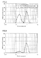
- FIG. 3 shows particle size distributions (i.e., frequency distributions) of the first CeZrRh-based mixed oxide powder and the second CeZrRh-based mixed oxide powder.
- the particle size distributions were measured with a laser diffraction particle size distribution analyzer produced by SHIMADZU CORPORATION.
- These CeZrRh-based mixed oxide powders have different peaks in particle size distribution.
- the particle size distribution of the first CeZrRh-based mixed oxide powder has a peak in the particle size range from 100 nm to 300 nm, both inclusive.
- the particle size distribution of the second CeZrRh-based mixed oxide powder has a peak in the particle size range from 550 nm to 1200 nm, both inclusive.
- the particle size in cumulative distribution for 10%, by mass is 107 mn
- the particle size in cumulative distribution for 50%, by mass is 184 nm
- the particle size in cumulative distribution for 90%, by mass is 287 nm. That is, the particle size in cumulative distribution for 10%, by mass, is 100 nm or more, and the particle size in cumulative distribution for 90%, by mass, is 300 nm or less.
- the particle size in cumulative distribution for 10%, by mass is 576 nm
- the particle size in cumulative distribution for 50%, by mass, is 848 nm
- the particle size in cumulative distribution for 90%, by mass is 1160 nm. That is, the particle size in cumulative distribution for 10%, by mass, is 550 nm or more, and the particle size in cumulative distribution for 90%, by mass, is 1200 nm or less.
- the concentrations of Rh in the particle surfaces (to a depth of several nanometers) in five selected regions (each having a diameter of several micrometers) were measured by X-ray photoelectron spectroscopy (XPS).
- the concentrations of Rh in the particle surfaces in five selected regions were measured by XPS.
- Rh concentrations i.e., the ratios of the peak area of Rh to the peak area values of all the elements.
- Table 1 shows the results. [Table 1] Surface Rh concentration (at%) Region 1 Region 2 Region 3 Region 4 Region 5 First CeZrRh-based mixed oxide powder 0.071 0.079 0.082 0.084 0.090 Second CeZrRh-based mixed oxide powder 0.040 0.045 0.047 0.052 0.059
- the Rh concentration in the particle surfaces of the first CeZrRh-based mixed oxide powder is in the range from 0.07 atomic percent (hereinafter referred to as "at.%") to 0.09 at.%, both inclusive.
- the Rh concentration in the particle surfaces of the second CeZrRh-based mixed oxide powder is in the range from 0.04 at.% to 0.06 at.%, both inclusive. That is, the first CeZrRh-based mixed oxide powder whose particle size has been reduced by grinding has a higher Rh concentration in the particle surfaces than that of the second CeZrRh-based mixed oxide powder before grinding.
- the second CeZrRh-based mixed oxide particles have a particle size larger than that of the first CeZrRh-based mixed oxide particles, and thus, the amount of Rh buried in the second CeZrRh-based mixed oxide particles is larger than that in the first CeZrRh-based mixed oxide particles.
- Rh buried in the particles is partially exposed at the surfaces of ground particles (i.e., the first CeZrRh-based mixed oxide particles). At least part of Rh exposed by the grinding is detected as Rh radiating a wavelength specific to this element (Rh) in measurement regions for XPS. This result is considered to cause the Rh concentration in the particle surfaces of the first CeZrRb-based mixed oxide powder obtained by XPS to be higher than that of the second CeZrRh-based mixed oxide powder.
- the fact that the Rh concentration of the first CeZrRh-based mixed oxide powder is higher than that of the second CeZrRh-based mixed oxide powder means that Rh buried in the particles comes to be exposed at the particle surface as a result of grinding. Accordingly, the amount of Rh exposed at the particle surfaces in the first CcZrRh-based mixed oxide powder is larger than that in the second CeZrRh-based mixed oxide powder, when compared to each other per a unit mass.
- a CeZrNd mixed oxide (where CeO 2 : ZrO 2 : Nd 2O3 .... 23 : 67 : 10 (mass ratio)) powder, a Pd/La-containing alumina powder in which Pd was carried on Al 2 O 3 containing 4%, by mass, of La 2 O 3 , a Pd/CeZrNd mixed oxide powder in which Pd was carried on a CeZrNd mixed oxide (where CeO 2 : ZrO 2 : Nd 2 O 3 23 : 67 : 10 (mass ratio)) powder, and zirconyl nitrate (a binder) were mixed together with ion-exchanged water to produce a slurry, and a support was wash-coated with the slurry, thereby forming a lower catalyst layer.
- the above-mentioned carrying of Pd was performed by evaporation to dryness. In the other Examples and Comparative Examples which will be described later, the evaporation to dryness was also
- a cordierite honeycomb support (having a volume of 1 L) having a cell wall thickness of 3.5 mil (8.89 ⁇ 10 -2 mm) and including 600 cells per square inch (645.16 mm 2 ) was used.
- This support was also used in the other Examples and Comparative Examples which will be described later.
- Table 2 shows the contents of catalyst components and other materials (in terms of mass per 1 L of the support).
- a Rh-doped CeZrNd sol in which the first CeZrRh-based mixed oxide powder was dispersed, a Rh/second CeZrRh-bascd mixed oxide powder, a Rh/ZrLa-alumina powder, and a La-containing alumina (containing 4%, by mass, of La 2 O 3 ) powder were mixed together with ion-exchanged water to produce a slurry, and the lower catalyst layer was wash-coated with the slurry, thereby forming an upper catalyst layer.
- the second CeZrRh-based mixed oxide powder was impregnated with a Rh nitrate solution, dried at 200°C for two hours, and calcined at 500°C for two hours so that Rh was carried on the Rh-doped second CeZrRh-based mixed oxide powder.
- the Rh/ZrLa-alumina powder was prepared in the following manner. Specifically, an activated alumina powder was dispersed in a mixed solution of zirconium nitrate and lanthanum nitrate, and aqueous ammonia was added to the resultant solution to produce a precipitate. The precipitate was filtered, washed, dried at 200°C for two hours, and calcined at 500°C for two hours, thereby obtaining activated alumina particles whose surfaces were coated with a ZrLa mixed oxide. The obtained activated alumina particles were mixed with a rhodium nitrate solution, and subjected to evaporation to dryness, thereby obtaining a Rh/ZrLa-alumina powder.
- Rh-doped CeZrNd sol serves as a binder in the upper catalyst layer, no dedicated binder material (i.e., zirconyl nitrate) is contained.
- the content of each component shown in Table 2 is expressed in terms of dry weight.
- FIG. 4 shows a particle size distribution of the CeZrRh-based mixed oxide powder in the upper catalyst layer (i.e., a particle size distribution of a mixture of the first CeZrRh-based mixed oxide powder and the second CeZrRh-based mixed oxide powder).
- This particle size distribution has two peaks respectively in the particle size range from 100 nm to 300 nm, both inclusive, and the particle size range from 550 nm to 1200 nm, both inclusive.
- the first particle group having a small particle size relative to a valley (around 450 nm (i.e., 0.45 ⁇ m)) between these peaks has a peak around 200 nm (i.e., 0.2 ⁇ m), whereas the second particle group having a large particle size relative to the valley has a peak around 850 nm (i.e., 0.85 ⁇ m).
- FIGS. 3 and 4 show that a large part of the first particle group is made of the first CeZrRh-based mixed oxide powder, and a large part of the second particle group is made of the second CeZrRh-based mixed oxide powder.
- the first CeZrRh-based mixed oxide powder is substantially uniformly dispersed in the upper catalyst layer. Accordingly, part of the first CeZrRh-based mixed oxide particles is carried on the surfaces of the large-size Rh/second CeZrRh-based mixed oxide particles, the Rh/ZrLa-alumina particles, and the La-containing alumina particles.
- the first CeZrRh-based mixed oxide powder serves as a binder in the upper catalyst layer.
- the lower catalyst layer of Example 2 had the same composition as that of Example 1 except that a first CeZrRh-based mixed oxide powder (10.000 g/L) was included instead of zirconyl nitrate (a binder) of Example 1.
- the upper catalyst layer of Example 2 had the same composition as that of Example 1 except that the amount of the Rh/second CeZrRh-based mixed oxide was 50.012 g/L (where the second CeZrRh-based mixed oxide powder: 50.000 g/L and the amount ofRh carried as a result of impregnation: 0.012 g/L).
- FIG. 5 shows a particle size distribution of the CeZrRh-based mixed oxide powder in the upper catalyst layer (i.e., a particle size distribution of a mixture of the first CeZrRh-based mixed oxide powder and the second CeZrRh-based mixed oxide powder).
- This particle size distribution has two peaks respectively in the particle size range from 100 nm to 300 nm, both inclusive, and the particle size range from 550 nm to 1200 nm, both inclusive.
- the first particle group with a small size relative to a valley (around 450 nm (i.e., 0.45 ⁇ m)) between these peaks has a peak around 200 nm (i.e., 0.2 ⁇ m), whereas the second particle group with a large size relative to the valley has a peak around 850 nm (i.e., 0.85 ⁇ m).
- Example 2 the first CeZrRh-based mixed oxide powder was included in both of the upper catalyst layer and the lower catalyst layer, and substantially uniformly dispersed in each of the layers. Accordingly, in the same manner as in Example 1, in the upper catalyst layer, part of the first CeZrRh-based mixed oxide particles was carried on the surfaces of the large-size Rh/second CeZrRh-based mixed oxide particles, the Rh/ZrLa-alumma particles, and the La-containing alumina particles. In addition, the first CeZrRh-based mixed oxide powder served as a binder in the upper catalyst layer.
- part of the first CeZrRh-based mixed oxide powder was also carried on CeZrNd mixed oxide particles, the Pd/La-containing alumina particles, and Pd/CeZrNd mixed oxide particles.
- the first CeZrRh-based mixed oxide powder served as a binder in the lower catalyst layer.
- the lower catalyst layer of Comparative Example 1 had the same composition as that of Example 1.
- the upper catalyst layer of Comparative Example 1 had the same composition as that of Example 1 except that zirconyl nitrate (a binder) (10.000 g/L) was included instead of the first CeZrRh-based mixed oxide powder of Example 1, and that the amount of the Rh/second CeZrRh-based mixed oxide powder was 70.012 g/L (where the second CeZrRh-based mixed oxide powder: 70.000 g/L and the amount of Rh carried as a result of impregnation: 0.012 g/L).
- the amount of the second CeZrRh-based mixed oxide powder in the upper catalyst layer was equal to the sum of the amounts of the first CeZrRh-based mixed oxide powder and the second CeZrRh-based mixed oxide powder in the upper catalyst layer of Example 1.
- the catalysts of Examples 1 and 2 and Comparative Example 1 were subjected to bench aging.
- each catalyst was attached to an engine exhaust system, and a cycle of (1) causing exhaust gas with an A/F ratio of 14 to flow for 15 seconds, (2) causing exhaust gas with an A/F ratio of 17 to flow for 5 seconds, and then (3) causing exhaust gas with an A/F ratio of 14.7 to flow for 40 seconds, was repeated for 50 hours in total.
- the engine was driven such that the gas temperature at a catalyst entrance was kept at 900°C.
- a core sample having a support volume of about 25 mL (diameter: 25.4 mm and length: 50 mm) was cut out from each catalyst, and mounted to a model gas flow reactor. Then, the light-off temperature T50 (°C) concerning purification of HC, CO, and NOx was measured.
- the temperature T50 (°C) was the gas temperature at a catalyst entrance when purification efficiency reached 50% by gradually increasing the temperature of model gas flowing in the catalyst from room temperature.
- the model gas had an A/F ratio of 14.7 ⁇ 0.9.
- a mainstream gas with an A/F ratio of 14.7 was allowed to constantly flow, and a predetermined amount of gas for changing the A/F ratio was added in pulses at a rate of 1 Hz, so that the A/F ratio was forcedly oscillated within the range of ⁇ 0.9.
- the space velocity SV was set at 60000/h -1 , and the rate of temperature increase was set at 30°C/min.
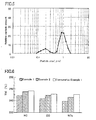
- FIG. 6 shows the measurement result of the light-off temperature T50.
- the light-off temperatures T50 of Examples 1 and 2 are lower than that of Comparative Example 1 for each of HC, CO, and NOx, and thus.
- Examples 1 and 2 exhibit excellent exhaust gas purification performance.
- the first CeZrRh-based mixed oxide powder having a small particle size and included in the catalyst layers of Examples 1 and 2 exhibits a lager proportion of a catalytic metal Rh exposed at the particle surfaces than that in the second CeZrRh-based mixed oxide powder having a large particle size. Accordingly, the oxygen storage/release capacity and the catalyst activity of the first CeZrRh-based mixed oxide powder are higher than those of the second CeZrRh-based mixed oxide powder. This result is considered to cause an improvement of exhaust gas purification performance in Examples 1 and 2.
- the first CeZrRh-based mixed oxide powder having a small particle size in Examples 1 and 2 is supported on, for example, the large-size Rh/second CeZrRh-based mixed oxide particles, the Rh/ZrLa-alumina particles, and the La-containing alumina particles. Accordingly, even when the first CeZrRh-based mixed oxide powder is exposed to high-temperature exhaust gas, agglomeration is not likely to occur. Further, since the first CeZrRh-based mixed oxide particles having high oxygen storage/release capacity are carried on other catalyst components such as the Rh/ZrLa-alumina particles, the activities of these catalyst components are also increased. This result is considered to contribute to excellent exhaust gas purification performance in Examples 1 and 2.
- Example 1 the light-off temperature in Example 1 is lower than that in Example 2. This phenomenon is considered to be because the amount of the second CeZrRh-based mixed oxide powder in the upper catalyst layer of Example 2 is smaller than that of Example 1.
- the first CeZrRh-based mixed oxide powder is also added to the lower catalyst layer. This addition does not greatly contribute to improvement of exhaust gas purification performance, and rather, degradation of catalyst performance due to a decrease in the amount of the second CeZrRh-based mixed oxide powder in the upper catalyst layer improves the exhaust gas purification performance.
- This comparison between Examples 1 and 2 shows that the addition of the first CeZrRh-based mixed oxide powder to the upper catalyst layer can more greatly improve exhaust gas purification performance than the addition of the first CeZrRh-based mixed oxide powder to the lower catalyst layer.
- both of the first mixed oxide particle component and the second mixed oxide particle component are of a Rh-doped type, i.e., contain Rh as a catalytic metal X.
- the first mixed oxide particle component is of a Rh-doped type
- the second mixed oxide particle component is not of a Rh-doped type, but of a Rh post-carried type.
- the catalyst layer is a single layer. Specifically, a catalyst layer is formed by using, as a binder material, Rh-doped mixed oxide particles which are a first mixed oxide particle component. This catalyst layer includes a Rh/CeZrNd material which is a second mixed oxide particle component. Examples 3 to 6 and Comparative Example 2 to 5 of this embodiment will be described hereinafter.
- Rh-doped CeZr sol, a Rh/CeZrNd material, and ion-exchanged water were mixed together to produce a slurry.
- a honeycomb support was coated with the slurry, thereby forming a catalyst layer.
- the Rh-doped CeZr sol was prepared by the same method as that for the Rh-doped CeZrNd sol of Example I except that a mixture of cerium nitrate hexahydrate, a zirconyl oxynitrate solution, and a rhodium nitrate solution dissolved in ion-exchanged water was used as a nitrate solution.
- the particle size distribution (i.e., frequency distribution) of the Rh-doped CeZr sol had a peak in the particle size range from 100 nm to 300 nm, both inclusive.
- Rh was carried on Zr-rich CeZrNd mixed oxide particles.
- the particle size distribution (i.e., frequency distribution) of the CeZrNd mixed oxide particles had a peak in the particle size range from 550 nm to 1200 nm, both inclusive.
- the amount of the Rh-doped CeZr mixed oxide powder (a binder) was 12 g/L, and the amount of the Rh/CeZrNd material was 70 g/L.
- a catalyst having the same composition as that of Example 3 was prepared except for employing a Rh-doped CeZrNdY sol instead of the Rh-doped CeZr sol.
- Rh-doped CeZrNdY sol was prepared by the same method as that for the Rh-doped CeZrNd sol of Example 1 except that a mixture of cerium, nitrate hexahydrate, a zirconyl oxynitrate solution, neodymium nitrate hexahydrate, yttrium nitrate hexahydrate, and a rhodium nitrate solution dissolved in ion-exchanged water was used as a nitrate solution.
- the particle size distribution (i.e., frequency distribution) of the Rh-doped CeZrNdY sol had a peak in the particle size range from 100 nm to 300 nm, both inclusive.
- a catalyst having the same composition as that of Example 3 was prepared except for employing a Rh-doped CeO 2 sol instead of the Rh-doped CeZr sol.
- the Rh-doped CeO 2 sol was obtained by dispersing, in water, a Rh-doped CeO 2 mixed oxide powder (with a Rh concentration of 0.05% by mass) in which CeO 2 was doped with Rh.
- the Rh-doped CeO 2 sol was prepared by the same method as that for the Rh-doped CeZrNd sol of Example 1 except that a mixture of cerium nitrate hexahydrate and a rhodium nitrate solution dissolved in ion-exchanged water was used as a nitrate solution.
- the particle size distribution (i.e., frequency distribution) of the Rh-doped CeO 2 sol had a peak in the particle size range from 100 nm to 300 nm, both inclusive.
- a catalyst having the same composition as that of Example 3 was prepared except for employing a Rh-doped CeZrNd sol instead of the Rh-doped CeZr sol, and employing a Ce-rich Rh/CeZrNd material instead of the Zr-rich Rh/CeZrNd material.
- the Rh-doped CeZrNd sol was obtained by the same method as that for the Rh-doped CeZrNd sol of Example 1.
- the particle size distribution (i.e., frequency distribution) of the Rh-doped CeZrNd sol of this example also had a peak in the particle size range from 100 nm to 300 nm, both inclusive.
- Rh was carried on the Ce-rich CeZrNd mixed oxide particles.
- the particle size distribution (i.e., frequency distribution) of the CeZrNd mixed oxide particles had a peak in the particle size range from 550 nm to 1200 nm, both inclusive.
- a catalyst having the same composition as that of Example 3 was prepared except for employing a ZrO 2 sol (not doped with Rh) instead of the Rh-doped CeZr sol, and setting the amount of the carried Rh/CeZrNd material at 75 g/L in order to set the amount of carried Rh at a value equal to that in Example 3.
- the ZrO 2 sol was obtained by dispersing ZrO 2 powder in water.
- a catalyst having the same composition as that of Example 3 was prepared except for employing a CeZr sol (not doped with Rh) instead of the Rh-doped CeZr sol, and setting the amount of the carried Rh/CeZrNd material at 75 g/L in order to set the amount of carried Rh at a value equal to that in Example 3.
- a catalyst having the same composition as that of Example 3 was prepared except for employing a CeO 2 sol (not doped with Rh) instead of the Rh-doped CeZr sol, and setting the amount of the carried Rh/CeZrNd material at 75 g/L in order to set the amount of carried Rh at a value equal to that in Example 3.
- the CeO 2 sol was obtained by dispersing CeO 2 powder in water.
- a catalyst having the same composition as that of Example 3 was prepared except for employing a ZrO 2 sol which was identical to that used in Comparative Example 2 instead of the Rh-doped CeZr sol, employing a Ce-rich Rh/CeZrNd material instead of the Zr-rich Rh/CeZrNd material, and setting the amount of the carried Rh/CeZrNd material at 75 g / L in order to set the amount of carried Rh at a value equal to that in Example 3.
- a single catalyst layer is employed as in Embodiment 2-1.
- the single catalyst layer includes: Rh-doped mixed oxide particles (a binder material) as a first mixed oxide particle component; a Zr-rich Rh/CeZrNd material as a second mixed oxide particle component; and Rh/ZrLa-alumma. Examples 7-10 and Comparative Examples 6-9 of EMBODIMENT 2-2 will be described hereinafter.
- Example 7 the catalyst layer of Example 3 further included Rh/ZrLa-alumina.
- a Rh-doped CeZr mixed oxide powder (a binder) in a Rh-doped CeZr sol was 12g/L
- a Rh/CeZrNd material was 70 g/L
- Rh/ZrLa-alumina was 30 g/L.
- a catalyst having the same composition as that of Example 7 was prepared except for employing a Rh-doped CeZrNdY sol which was identical to that used in Example 4 instead of the Rh-doped CeZr sol.
- a catalyst having the same composition as that of Example 7 was prepared except for employing a CeO 2 sol which was identical to that used in Example 5 instead of the Rh-doped CeZr sol.
- a catalyst having the same composition as that of Example 7 was prepared except for employing a Rh-doped CeZrNd sol which was identical to that used in Example 6 instead of the Rh-doped CeZr sol, and employing a Co-rich Rh/CeZrNd material which was identical to that used in Example 6 instead of the Zr-rich Rh/CeZrNd material.
- a catalyst having the same composition as that of Example 7 was prepared except for employing a ZrO 2 sol which was identical to that used in Comparative Example 2 instead of the Rh-doped CeZr sol, and setting the amount of the carried Rh/CeZrNd material at 75 g/L in order to set the amount of carried Rh at a value equal to that in Example 7.
- a catalyst having the same composition as that of Example 7 was prepared except for employing a CeZr sol which was identical to that used in Comparative Example 3 instead of the Rh-doped CeZr sol, and setting the amount of the carried Rh/CeZrNd material at 75 g/L in order to set the amount of carried Rh at a value equal to that in Example 7.
- a catalyst having the same composition as that of Example 7 was prepared except for employing a CeO 2 sol which was identical to that used in Comparative Example 4 instead of the Rh-doped CeZr sol, and setting the amount of the carried Rh/CeZrNd material at 75 g/L in order to set the amount of carried Rh at a value equal to that in Example 7.
- a catalyst having the same composition as that of Example 7 was prepared except for employing a ZrO 2 sol which was identical to that used in Comparative Example 2 instead of the Rh-doped CeZr sol, employing a Ce-rich Rh/CeZrNd material which was identical to that used in Example 6 instead of the Zr-rich Rh/CeZrNd material, and setting the amount of the carried Rh/CeZrNd material at 75 g/L in order to set the amount of carried Rh at a value equal to that in Example 7.
- a catalyst having a double-layer structure and illustrated in FIG. 1 includes upper and lower catalyst layers having the following compositions.
- the upper catalyst layer included a mixture of: Rh-doped CeZrNdY, as a binder, in a Rh-doped CeZrNdY sol which was identical to that in Example 4; a Zr-rich Rh/CeZrNd material which was identical to that in Example 4; Rh/ZrLa-alumina which was identical to that in Example 7; and La-alumina (carrying no catalytic metal).
- the lower catalyst layer included a mixture of: a Pd/CeZrNd material; Pd/La-alumina; a CeZrNd material (carrying no catalytic metal); and ZrO 2 , as a binder, in a ZrO 2 sol.
- La-alumina (carrying no catalytic metal) was activated alumina containing 4%, by mass, of La 2 O 3 .
- Pd/La-alumina Pd was carried on La-alumina containing 4%, by mass of La 2 O 3 , and the Pd concentration was 0.86% by mass.
- the CeZrNd material (carrying no catalytic metal) was the same as the CeZrNd material in the Pd/CeZrNd material.
- Rh-doped CeZrNdY in the upper catalyst layer was 12 g/L
- the Zr-rich Rh/CeZrNd material was 70 g/L
- Rh/ZrLa-alumina was 30 g/L
- La-alumina (carrying no catalytic metal) was 10 g/L.
- the Pd/CeZrNd material was 35 g/L
- Pd/La-alumina was 45 g/L
- the CeZrNd material (carrying no catalytic metal) was 20 g/L
- the ZrO 2 binder was 11 g/L.
- a catalyst having the same composition as that of Example 11 was prepared except for employing a ZrO 2 binder, as a binder of the upper catalyst layer, instead of Rh-doped CeZrNdY, and setting the amount of the carried Rh/CeZrNd material at 75 g/L in order to set the amount of carried Rh at a value equal to that in Example 11.
- Embodiments 2 and 3 After bench aging has been performed on each catalyst of Embodiments 2 and 3 in the same manner as in Embodiment 1, a core sample having a support volume of about 25 mL (diameter: 25.4 mm and length: 50 mm) was cut out from the catalyst, and the light-off temperature T50 (°C) and the exhaust gas purification efficiency C400 in HC, CO, and NOx purification were measured under the same conditions as those in Embodiment 1.
- the exhaust gas purification efficiency C400 was the purification efficiency for each of HC, CO, and NOx measured when the temperature of model exhaust gas at a catalyst entrance was 400°C. Table 4 shows the results.
- Example 3-5 shows that even with the same Rh amount in the catalyst layer, the use of a Rh-doped Ce-containing oxide sol as a binder material improves light-off performance of the catalyst and enhances exhaust gas purification efficiency.
- Example 4 employing the Rh-doped CeZrNdY sol shows particularly excellent results.
- Comparison between Examples 7-9 and Comparative Examples 6-8 also shows that the use of the Rh-doped Ce-containing oxide sol is advantageous. The results on Examples 7-9 also show that the Rh-doped CeZrNd sol is particularly advantageous.
- Comparison between Example 6 and Comparative Example 5 and comparison between Example 10 and Comparative Example 9 show advantageousness of the Rh-doped Ce-containing oxide sol even in a case where another component is a Ce-rich Rh/CeZrNd material. Comparison between Example 11 and Comparative Example 10 shows advantageousness of the Rh-doped Ce-containing oxide sol in the double-layer structure.
Landscapes
- Chemical & Material Sciences (AREA)
- Engineering & Computer Science (AREA)
- Materials Engineering (AREA)
- Chemical Kinetics & Catalysis (AREA)
- Organic Chemistry (AREA)
- Health & Medical Sciences (AREA)
- Combustion & Propulsion (AREA)
- Biomedical Technology (AREA)
- Environmental & Geological Engineering (AREA)
- Analytical Chemistry (AREA)
- General Chemical & Material Sciences (AREA)
- Oil, Petroleum & Natural Gas (AREA)
- Exhaust Gas Treatment By Means Of Catalyst (AREA)
- Catalysts (AREA)
- Exhaust Gas After Treatment (AREA)
Applications Claiming Priority (2)
| Application Number | Priority Date | Filing Date | Title |
|---|---|---|---|
| JP2009189182 | 2009-08-18 | ||
| JP2010070930A JP5515936B2 (ja) | 2009-08-18 | 2010-03-25 | 排気ガス浄化用触媒 |
Publications (2)
| Publication Number | Publication Date |
|---|---|
| EP2298444A1 true EP2298444A1 (de) | 2011-03-23 |
| EP2298444B1 EP2298444B1 (de) | 2012-05-09 |
Family
ID=42830057
Family Applications (1)
| Application Number | Title | Priority Date | Filing Date |
|---|---|---|---|
| EP10168494A Not-in-force EP2298444B1 (de) | 2009-08-18 | 2010-07-06 | Abgasreinigungskatalysator |
Country Status (4)
| Country | Link |
|---|---|
| US (1) | US8912116B2 (de) |
| EP (1) | EP2298444B1 (de) |
| JP (1) | JP5515936B2 (de) |
| AT (1) | ATE556770T1 (de) |
Cited By (5)
| Publication number | Priority date | Publication date | Assignee | Title |
|---|---|---|---|---|
| EP2431092A4 (de) * | 2009-04-14 | 2013-12-04 | Cataler Corp | Abgasreinigungskatalysator und verfahren zu seiner herstellung |
| EP2602022A4 (de) * | 2010-08-05 | 2017-09-06 | DOWA Electronics Materials Co., Ltd. | Verfahren zur herstellung einer katalysatorzusammensetzung, katalysatorzusammensetzung, dieselpartikelfilter damit, und abgasreinigungssystem |
| CN108698022A (zh) * | 2016-02-25 | 2018-10-23 | 株式会社科特拉 | 废气净化催化剂及其制造方法 |
| EP3268115A4 (de) * | 2015-02-11 | 2019-03-06 | SDCmaterials, Inc. | Mager-nox-fallen, einfangmaterialien, washcoats und verfahren zur herstellung und verwendung davon |
| CN113557089A (zh) * | 2019-03-14 | 2021-10-26 | 巴斯夫公司 | 用于增强催化剂载体涂料粘附性的粘合剂组合物 |
Families Citing this family (13)
| Publication number | Priority date | Publication date | Assignee | Title |
|---|---|---|---|---|
| JP5515939B2 (ja) * | 2010-03-26 | 2014-06-11 | マツダ株式会社 | 排気ガス浄化用触媒 |
| JP5488215B2 (ja) | 2010-06-07 | 2014-05-14 | マツダ株式会社 | 排気ガス浄化用触媒 |
| JP5488214B2 (ja) | 2010-06-07 | 2014-05-14 | マツダ株式会社 | 排気ガス浄化用触媒 |
| JP2012154259A (ja) | 2011-01-26 | 2012-08-16 | Mazda Motor Corp | 排気ガス浄化用触媒装置 |
| JP5594161B2 (ja) | 2011-01-26 | 2014-09-24 | マツダ株式会社 | 排気ガス浄化用触媒装置 |
| JP5760623B2 (ja) * | 2011-04-11 | 2015-08-12 | マツダ株式会社 | 排気ガス浄化用触媒及びその製造方法 |
| JP5992192B2 (ja) * | 2012-03-30 | 2016-09-14 | 三井金属鉱業株式会社 | パラジウム触媒 |
| JP5982987B2 (ja) * | 2012-04-23 | 2016-08-31 | マツダ株式会社 | 排気ガス浄化用触媒材を含有する排気ガス浄化用触媒 |
| US9156025B2 (en) * | 2012-11-21 | 2015-10-13 | SDCmaterials, Inc. | Three-way catalytic converter using nanoparticles |
| JP5942894B2 (ja) | 2013-02-21 | 2016-06-29 | マツダ株式会社 | 排気ガス浄化用触媒の製造方法 |
| JP6175275B2 (ja) * | 2013-05-16 | 2017-08-02 | 株式会社キャタラー | 排ガス浄化用触媒 |
| CN104661749B (zh) * | 2013-05-27 | 2017-03-15 | 马自达汽车株式会社 | 尾气净化用催化剂及其制备方法 |
| WO2017163916A1 (ja) * | 2016-03-25 | 2017-09-28 | 株式会社キャタラー | 排ガス浄化用触媒及びその製造方法並びにそれを用いた排ガス浄化装置 |
Citations (7)
| Publication number | Priority date | Publication date | Assignee | Title |
|---|---|---|---|---|
| JP2005161143A (ja) | 2003-12-01 | 2005-06-23 | Mazda Motor Corp | 排気ガス浄化用触媒材料、及びその製造方法 |
| JP2006334490A (ja) | 2005-06-01 | 2006-12-14 | Mazda Motor Corp | 排気ガス浄化用触媒 |
| JP2007031192A (ja) | 2005-07-25 | 2007-02-08 | Taki Chem Co Ltd | セリア−ジルコニア固溶体ゾル及びその製造方法 |
| JP2008062130A (ja) * | 2006-09-05 | 2008-03-21 | Mazda Motor Corp | 酸素吸蔵材粒子を含有する排気ガス浄化用触媒 |
| EP1952876A1 (de) * | 2007-01-25 | 2008-08-06 | Nissan Motor Co., Ltd. | Abgasreinigungskatalysator und zugehöriges Herstellungsverfahren |
| EP2055366A1 (de) * | 2007-10-30 | 2009-05-06 | Mazda Motor Corporation | Katalysatorgestützter Partikelfilter |
| WO2010101223A1 (ja) * | 2009-03-04 | 2010-09-10 | 日産自動車株式会社 | 排気ガス浄化触媒及びその製造方法 |
-
2010
- 2010-03-25 JP JP2010070930A patent/JP5515936B2/ja active Active
- 2010-07-06 EP EP10168494A patent/EP2298444B1/de not_active Not-in-force
- 2010-07-06 AT AT10168494T patent/ATE556770T1/de active
- 2010-07-29 US US12/846,486 patent/US8912116B2/en not_active Expired - Fee Related
Patent Citations (7)
| Publication number | Priority date | Publication date | Assignee | Title |
|---|---|---|---|---|
| JP2005161143A (ja) | 2003-12-01 | 2005-06-23 | Mazda Motor Corp | 排気ガス浄化用触媒材料、及びその製造方法 |
| JP2006334490A (ja) | 2005-06-01 | 2006-12-14 | Mazda Motor Corp | 排気ガス浄化用触媒 |
| JP2007031192A (ja) | 2005-07-25 | 2007-02-08 | Taki Chem Co Ltd | セリア−ジルコニア固溶体ゾル及びその製造方法 |
| JP2008062130A (ja) * | 2006-09-05 | 2008-03-21 | Mazda Motor Corp | 酸素吸蔵材粒子を含有する排気ガス浄化用触媒 |
| EP1952876A1 (de) * | 2007-01-25 | 2008-08-06 | Nissan Motor Co., Ltd. | Abgasreinigungskatalysator und zugehöriges Herstellungsverfahren |
| EP2055366A1 (de) * | 2007-10-30 | 2009-05-06 | Mazda Motor Corporation | Katalysatorgestützter Partikelfilter |
| WO2010101223A1 (ja) * | 2009-03-04 | 2010-09-10 | 日産自動車株式会社 | 排気ガス浄化触媒及びその製造方法 |
Cited By (11)
| Publication number | Priority date | Publication date | Assignee | Title |
|---|---|---|---|---|
| EP2431092A4 (de) * | 2009-04-14 | 2013-12-04 | Cataler Corp | Abgasreinigungskatalysator und verfahren zu seiner herstellung |
| EP2602022A4 (de) * | 2010-08-05 | 2017-09-06 | DOWA Electronics Materials Co., Ltd. | Verfahren zur herstellung einer katalysatorzusammensetzung, katalysatorzusammensetzung, dieselpartikelfilter damit, und abgasreinigungssystem |
| EP3268115A4 (de) * | 2015-02-11 | 2019-03-06 | SDCmaterials, Inc. | Mager-nox-fallen, einfangmaterialien, washcoats und verfahren zur herstellung und verwendung davon |
| CN108698022A (zh) * | 2016-02-25 | 2018-10-23 | 株式会社科特拉 | 废气净化催化剂及其制造方法 |
| EP3421127A4 (de) * | 2016-02-25 | 2019-07-10 | Cataler Corporation | Abgasreinigungskatalysator und herstellungsverfahren dafür |
| US10695752B2 (en) | 2016-02-25 | 2020-06-30 | Cataler Corporation | Exhaust-gas purifying catalyst and manufacturing method therefor |
| CN108698022B (zh) * | 2016-02-25 | 2021-10-26 | 株式会社科特拉 | 废气净化催化剂及其制造方法 |
| CN113557089A (zh) * | 2019-03-14 | 2021-10-26 | 巴斯夫公司 | 用于增强催化剂载体涂料粘附性的粘合剂组合物 |
| EP3938100A4 (de) * | 2019-03-14 | 2023-01-11 | BASF Corporation | Bindemittelzusammensetzung für erhöhte haftung des katalysator-washcoats |
| CN113557089B (zh) * | 2019-03-14 | 2024-11-01 | 巴斯夫公司 | 用于增强催化剂载体涂料粘附性的粘合剂组合物 |
| US12269013B2 (en) | 2019-03-14 | 2025-04-08 | Basf Mobile Emissions Catalysts Llc | Binder composition for enhanced catalyst washcoat adhesion |
Also Published As
| Publication number | Publication date |
|---|---|
| US20110045968A1 (en) | 2011-02-24 |
| ATE556770T1 (de) | 2012-05-15 |
| JP2011062683A (ja) | 2011-03-31 |
| EP2298444B1 (de) | 2012-05-09 |
| US8912116B2 (en) | 2014-12-16 |
| JP5515936B2 (ja) | 2014-06-11 |
Similar Documents
| Publication | Publication Date | Title |
|---|---|---|
| EP2298444B1 (de) | Abgasreinigungskatalysator | |
| JP5515939B2 (ja) | 排気ガス浄化用触媒 | |
| EP1985354B1 (de) | Abgasreinigungskatalysator und Herstellungsverfahren dafür | |
| EP1834694B1 (de) | Katalysator zur Abgasreinigung, Herstellungsverfahren dafür sowie Verfahren zur Abgasreinigung mit dem Katalysator | |
| EP1952876A1 (de) | Abgasreinigungskatalysator und zugehöriges Herstellungsverfahren | |
| JP2008168278A (ja) | 排ガス浄化用触媒及びその製造方法 | |
| WO2011080567A1 (en) | Exhaust gas purifying catalyst | |
| JP7187654B2 (ja) | 排ガス用浄化触媒組成物、及び自動車用排ガス浄化触媒 | |
| CA2562556C (en) | Process for producing metal oxide particle and exhaust gas purifying catalyst | |
| US9415383B2 (en) | Exhaust gas purification catalyst | |
| EP2055365B1 (de) | Katalysatorgestützter Partikelfilter | |
| EP1728552A1 (de) | Abgasreinigungskatalysator | |
| JP5589321B2 (ja) | 排気ガス浄化用触媒およびその製造方法 | |
| EP1632288B1 (de) | Abgasreinigungskatalysator und Sauerstoffspeicherkomponente dafür | |
| JP2011255270A (ja) | 排気ガス浄化用触媒 | |
| JP6146436B2 (ja) | 排気ガス浄化用触媒 | |
| JP6504096B2 (ja) | 排気ガス浄化用触媒 | |
| US8932982B2 (en) | Exhaust gas purification catalyst | |
| EP4066940B1 (de) | Abgasreinigungskatalysator | |
| JP6532825B2 (ja) | 排ガス浄化用触媒 | |
| EP2177258B1 (de) | Abgasreinigungskatalysator | |
| EP4316650A1 (de) | Abgasreinigungskatalysator und abgasreinigungssystem |
Legal Events
| Date | Code | Title | Description |
|---|---|---|---|
| PUAI | Public reference made under article 153(3) epc to a published international application that has entered the european phase |
Free format text: ORIGINAL CODE: 0009012 |
|
| AK | Designated contracting states |
Kind code of ref document: A1 Designated state(s): AL AT BE BG CH CY CZ DE DK EE ES FI FR GB GR HR HU IE IS IT LI LT LU LV MC MK MT NL NO PL PT RO SE SI SK SM TR |
|
| AX | Request for extension of the european patent |
Extension state: BA ME RS |
|
| 17P | Request for examination filed |
Effective date: 20110919 |
|
| GRAP | Despatch of communication of intention to grant a patent |
Free format text: ORIGINAL CODE: EPIDOSNIGR1 |
|
| RIN1 | Information on inventor provided before grant (corrected) |
Inventor name: IWAKUNI, HIDEHARU Inventor name: KAWABATA, HISAYA Inventor name: OCHI, YASUHIRO Inventor name: SHIGETSU, MASAHIKO Inventor name: AKAMINE, MASAAKI Inventor name: MINEOI, SUSUMU Inventor name: MURAKAMI, YUKI Inventor name: TAKAMI, AKIHIDE |
|
| GRAS | Grant fee paid |
Free format text: ORIGINAL CODE: EPIDOSNIGR3 |
|
| GRAA | (expected) grant |
Free format text: ORIGINAL CODE: 0009210 |
|
| AK | Designated contracting states |
Kind code of ref document: B1 Designated state(s): AL AT BE BG CH CY CZ DE DK EE ES FI FR GB GR HR HU IE IS IT LI LT LU LV MC MK MT NL NO PL PT RO SE SI SK SM TR |
|
| REG | Reference to a national code |
Ref country code: GB Ref legal event code: FG4D |
|
| REG | Reference to a national code |
Ref country code: AT Ref legal event code: REF Ref document number: 556770 Country of ref document: AT Kind code of ref document: T Effective date: 20120515 Ref country code: CH Ref legal event code: EP |
|
| REG | Reference to a national code |
Ref country code: IE Ref legal event code: FG4D |
|
| REG | Reference to a national code |
Ref country code: DE Ref legal event code: R096 Ref document number: 602010001400 Country of ref document: DE Effective date: 20120712 |
|
| REG | Reference to a national code |
Ref country code: NL Ref legal event code: VDEP Effective date: 20120509 |
|
| REG | Reference to a national code |
Ref country code: LT Ref legal event code: MG4D Effective date: 20120509 |
|
| PG25 | Lapsed in a contracting state [announced via postgrant information from national office to epo] |
Ref country code: NO Free format text: LAPSE BECAUSE OF FAILURE TO SUBMIT A TRANSLATION OF THE DESCRIPTION OR TO PAY THE FEE WITHIN THE PRESCRIBED TIME-LIMIT Effective date: 20120809 Ref country code: FI Free format text: LAPSE BECAUSE OF FAILURE TO SUBMIT A TRANSLATION OF THE DESCRIPTION OR TO PAY THE FEE WITHIN THE PRESCRIBED TIME-LIMIT Effective date: 20120509 Ref country code: CY Free format text: LAPSE BECAUSE OF FAILURE TO SUBMIT A TRANSLATION OF THE DESCRIPTION OR TO PAY THE FEE WITHIN THE PRESCRIBED TIME-LIMIT Effective date: 20120509 Ref country code: SE Free format text: LAPSE BECAUSE OF FAILURE TO SUBMIT A TRANSLATION OF THE DESCRIPTION OR TO PAY THE FEE WITHIN THE PRESCRIBED TIME-LIMIT Effective date: 20120509 Ref country code: LT Free format text: LAPSE BECAUSE OF FAILURE TO SUBMIT A TRANSLATION OF THE DESCRIPTION OR TO PAY THE FEE WITHIN THE PRESCRIBED TIME-LIMIT Effective date: 20120509 Ref country code: PL Free format text: LAPSE BECAUSE OF FAILURE TO SUBMIT A TRANSLATION OF THE DESCRIPTION OR TO PAY THE FEE WITHIN THE PRESCRIBED TIME-LIMIT Effective date: 20120509 Ref country code: IS Free format text: LAPSE BECAUSE OF FAILURE TO SUBMIT A TRANSLATION OF THE DESCRIPTION OR TO PAY THE FEE WITHIN THE PRESCRIBED TIME-LIMIT Effective date: 20120909 |
|
| REG | Reference to a national code |
Ref country code: AT Ref legal event code: MK05 Ref document number: 556770 Country of ref document: AT Kind code of ref document: T Effective date: 20120509 |
|
| PG25 | Lapsed in a contracting state [announced via postgrant information from national office to epo] |
Ref country code: SI Free format text: LAPSE BECAUSE OF FAILURE TO SUBMIT A TRANSLATION OF THE DESCRIPTION OR TO PAY THE FEE WITHIN THE PRESCRIBED TIME-LIMIT Effective date: 20120509 Ref country code: HR Free format text: LAPSE BECAUSE OF FAILURE TO SUBMIT A TRANSLATION OF THE DESCRIPTION OR TO PAY THE FEE WITHIN THE PRESCRIBED TIME-LIMIT Effective date: 20120509 Ref country code: GR Free format text: LAPSE BECAUSE OF FAILURE TO SUBMIT A TRANSLATION OF THE DESCRIPTION OR TO PAY THE FEE WITHIN THE PRESCRIBED TIME-LIMIT Effective date: 20120810 Ref country code: PT Free format text: LAPSE BECAUSE OF FAILURE TO SUBMIT A TRANSLATION OF THE DESCRIPTION OR TO PAY THE FEE WITHIN THE PRESCRIBED TIME-LIMIT Effective date: 20120910 Ref country code: LV Free format text: LAPSE BECAUSE OF FAILURE TO SUBMIT A TRANSLATION OF THE DESCRIPTION OR TO PAY THE FEE WITHIN THE PRESCRIBED TIME-LIMIT Effective date: 20120509 |
|
| PG25 | Lapsed in a contracting state [announced via postgrant information from national office to epo] |
Ref country code: BE Free format text: LAPSE BECAUSE OF FAILURE TO SUBMIT A TRANSLATION OF THE DESCRIPTION OR TO PAY THE FEE WITHIN THE PRESCRIBED TIME-LIMIT Effective date: 20120509 |
|
| PG25 | Lapsed in a contracting state [announced via postgrant information from national office to epo] |
Ref country code: DK Free format text: LAPSE BECAUSE OF FAILURE TO SUBMIT A TRANSLATION OF THE DESCRIPTION OR TO PAY THE FEE WITHIN THE PRESCRIBED TIME-LIMIT Effective date: 20120509 Ref country code: RO Free format text: LAPSE BECAUSE OF FAILURE TO SUBMIT A TRANSLATION OF THE DESCRIPTION OR TO PAY THE FEE WITHIN THE PRESCRIBED TIME-LIMIT Effective date: 20120509 Ref country code: AT Free format text: LAPSE BECAUSE OF FAILURE TO SUBMIT A TRANSLATION OF THE DESCRIPTION OR TO PAY THE FEE WITHIN THE PRESCRIBED TIME-LIMIT Effective date: 20120509 Ref country code: NL Free format text: LAPSE BECAUSE OF FAILURE TO SUBMIT A TRANSLATION OF THE DESCRIPTION OR TO PAY THE FEE WITHIN THE PRESCRIBED TIME-LIMIT Effective date: 20120509 Ref country code: EE Free format text: LAPSE BECAUSE OF FAILURE TO SUBMIT A TRANSLATION OF THE DESCRIPTION OR TO PAY THE FEE WITHIN THE PRESCRIBED TIME-LIMIT Effective date: 20120509 Ref country code: SK Free format text: LAPSE BECAUSE OF FAILURE TO SUBMIT A TRANSLATION OF THE DESCRIPTION OR TO PAY THE FEE WITHIN THE PRESCRIBED TIME-LIMIT Effective date: 20120509 Ref country code: CZ Free format text: LAPSE BECAUSE OF FAILURE TO SUBMIT A TRANSLATION OF THE DESCRIPTION OR TO PAY THE FEE WITHIN THE PRESCRIBED TIME-LIMIT Effective date: 20120509 |
|
| REG | Reference to a national code |
Ref country code: DE Ref legal event code: R097 Ref document number: 602010001400 Country of ref document: DE |
|
| PG25 | Lapsed in a contracting state [announced via postgrant information from national office to epo] |
Ref country code: MC Free format text: LAPSE BECAUSE OF NON-PAYMENT OF DUE FEES Effective date: 20120731 Ref country code: MK Free format text: LAPSE BECAUSE OF FAILURE TO SUBMIT A TRANSLATION OF THE DESCRIPTION OR TO PAY THE FEE WITHIN THE PRESCRIBED TIME-LIMIT Effective date: 20120509 Ref country code: IT Free format text: LAPSE BECAUSE OF FAILURE TO SUBMIT A TRANSLATION OF THE DESCRIPTION OR TO PAY THE FEE WITHIN THE PRESCRIBED TIME-LIMIT Effective date: 20120509 |
|
| PLBE | No opposition filed within time limit |
Free format text: ORIGINAL CODE: 0009261 |
|
| STAA | Information on the status of an ep patent application or granted ep patent |
Free format text: STATUS: NO OPPOSITION FILED WITHIN TIME LIMIT |
|
| 26N | No opposition filed |
Effective date: 20130212 |
|
| REG | Reference to a national code |
Ref country code: DE Ref legal event code: R084 Ref document number: 602010001400 Country of ref document: DE Effective date: 20130214 |
|
| REG | Reference to a national code |
Ref country code: FR Ref legal event code: ST Effective date: 20130329 |
|
| PG25 | Lapsed in a contracting state [announced via postgrant information from national office to epo] |
Ref country code: FR Free format text: LAPSE BECAUSE OF NON-PAYMENT OF DUE FEES Effective date: 20120731 Ref country code: ES Free format text: LAPSE BECAUSE OF FAILURE TO SUBMIT A TRANSLATION OF THE DESCRIPTION OR TO PAY THE FEE WITHIN THE PRESCRIBED TIME-LIMIT Effective date: 20120820 |
|
| REG | Reference to a national code |
Ref country code: IE Ref legal event code: MM4A |
|
| REG | Reference to a national code |
Ref country code: DE Ref legal event code: R097 Ref document number: 602010001400 Country of ref document: DE Effective date: 20130212 |
|
| PG25 | Lapsed in a contracting state [announced via postgrant information from national office to epo] |
Ref country code: IE Free format text: LAPSE BECAUSE OF NON-PAYMENT OF DUE FEES Effective date: 20120706 Ref country code: MT Free format text: LAPSE BECAUSE OF FAILURE TO SUBMIT A TRANSLATION OF THE DESCRIPTION OR TO PAY THE FEE WITHIN THE PRESCRIBED TIME-LIMIT Effective date: 20120509 Ref country code: BG Free format text: LAPSE BECAUSE OF FAILURE TO SUBMIT A TRANSLATION OF THE DESCRIPTION OR TO PAY THE FEE WITHIN THE PRESCRIBED TIME-LIMIT Effective date: 20120809 |
|
| PG25 | Lapsed in a contracting state [announced via postgrant information from national office to epo] |
Ref country code: AL Free format text: LAPSE BECAUSE OF FAILURE TO SUBMIT A TRANSLATION OF THE DESCRIPTION OR TO PAY THE FEE WITHIN THE PRESCRIBED TIME-LIMIT Effective date: 20120509 |
|
| PG25 | Lapsed in a contracting state [announced via postgrant information from national office to epo] |
Ref country code: TR Free format text: LAPSE BECAUSE OF FAILURE TO SUBMIT A TRANSLATION OF THE DESCRIPTION OR TO PAY THE FEE WITHIN THE PRESCRIBED TIME-LIMIT Effective date: 20120509 |
|
| PG25 | Lapsed in a contracting state [announced via postgrant information from national office to epo] |
Ref country code: LU Free format text: LAPSE BECAUSE OF NON-PAYMENT OF DUE FEES Effective date: 20120706 Ref country code: SM Free format text: LAPSE BECAUSE OF FAILURE TO SUBMIT A TRANSLATION OF THE DESCRIPTION OR TO PAY THE FEE WITHIN THE PRESCRIBED TIME-LIMIT Effective date: 20120509 |
|
| PG25 | Lapsed in a contracting state [announced via postgrant information from national office to epo] |
Ref country code: HU Free format text: LAPSE BECAUSE OF FAILURE TO SUBMIT A TRANSLATION OF THE DESCRIPTION OR TO PAY THE FEE WITHIN THE PRESCRIBED TIME-LIMIT Effective date: 20100706 |
|
| REG | Reference to a national code |
Ref country code: CH Ref legal event code: PL |
|
| GBPC | Gb: european patent ceased through non-payment of renewal fee |
Effective date: 20140706 |
|
| PG25 | Lapsed in a contracting state [announced via postgrant information from national office to epo] |
Ref country code: CH Free format text: LAPSE BECAUSE OF NON-PAYMENT OF DUE FEES Effective date: 20140731 Ref country code: LI Free format text: LAPSE BECAUSE OF NON-PAYMENT OF DUE FEES Effective date: 20140731 |
|
| PG25 | Lapsed in a contracting state [announced via postgrant information from national office to epo] |
Ref country code: GB Free format text: LAPSE BECAUSE OF NON-PAYMENT OF DUE FEES Effective date: 20140706 |
|
| PGFP | Annual fee paid to national office [announced via postgrant information from national office to epo] |
Ref country code: DE Payment date: 20190625 Year of fee payment: 10 |
|
| REG | Reference to a national code |
Ref country code: DE Ref legal event code: R119 Ref document number: 602010001400 Country of ref document: DE |
|
| PG25 | Lapsed in a contracting state [announced via postgrant information from national office to epo] |
Ref country code: DE Free format text: LAPSE BECAUSE OF NON-PAYMENT OF DUE FEES Effective date: 20210202 |