EP2298504B1 - Outil motorisé - Google Patents
Outil motorisé Download PDFInfo
- Publication number
- EP2298504B1 EP2298504B1 EP09762489A EP09762489A EP2298504B1 EP 2298504 B1 EP2298504 B1 EP 2298504B1 EP 09762489 A EP09762489 A EP 09762489A EP 09762489 A EP09762489 A EP 09762489A EP 2298504 B1 EP2298504 B1 EP 2298504B1
- Authority
- EP
- European Patent Office
- Prior art keywords
- power transmission
- clutch member
- side clutch
- torque
- speed change
- Prior art date
- Legal status (The legal status is an assumption and is not a legal conclusion. Google has not performed a legal analysis and makes no representation as to the accuracy of the status listed.)
- Not-in-force
Links
- 230000005540 biological transmission Effects 0.000 claims description 324
- 230000007246 mechanism Effects 0.000 claims description 187
- 230000008859 change Effects 0.000 claims description 125
- 238000005520 cutting process Methods 0.000 description 41
- 238000010276 construction Methods 0.000 description 23
- 230000006835 compression Effects 0.000 description 20
- 238000007906 compression Methods 0.000 description 20
- 230000002265 prevention Effects 0.000 description 16
- 230000004048 modification Effects 0.000 description 14
- 238000012986 modification Methods 0.000 description 14
- 230000000717 retained effect Effects 0.000 description 7
- 238000000034 method Methods 0.000 description 5
- 230000009471 action Effects 0.000 description 4
- 230000002411 adverse Effects 0.000 description 4
- 229910003460 diamond Inorganic materials 0.000 description 4
- 239000010432 diamond Substances 0.000 description 4
- 238000005553 drilling Methods 0.000 description 4
- 230000007257 malfunction Effects 0.000 description 4
- 238000005498 polishing Methods 0.000 description 4
- 238000000926 separation method Methods 0.000 description 4
- 238000005555 metalworking Methods 0.000 description 3
- 230000009467 reduction Effects 0.000 description 3
- 238000009966 trimming Methods 0.000 description 3
- 230000009194 climbing Effects 0.000 description 2
- 230000003247 decreasing effect Effects 0.000 description 2
- 238000006073 displacement reaction Methods 0.000 description 2
- 230000000694 effects Effects 0.000 description 2
- 238000013459 approach Methods 0.000 description 1
- 230000008901 benefit Effects 0.000 description 1
- 230000000881 depressing effect Effects 0.000 description 1
- 230000006872 improvement Effects 0.000 description 1
- 230000013011 mating Effects 0.000 description 1
- 238000003825 pressing Methods 0.000 description 1
- 230000008569 process Effects 0.000 description 1
- 238000011144 upstream manufacturing Methods 0.000 description 1
Images










Classifications
-
- B—PERFORMING OPERATIONS; TRANSPORTING
- B25—HAND TOOLS; PORTABLE POWER-DRIVEN TOOLS; MANIPULATORS
- B25F—COMBINATION OR MULTI-PURPOSE TOOLS NOT OTHERWISE PROVIDED FOR; DETAILS OR COMPONENTS OF PORTABLE POWER-DRIVEN TOOLS NOT PARTICULARLY RELATED TO THE OPERATIONS PERFORMED AND NOT OTHERWISE PROVIDED FOR
- B25F5/00—Details or components of portable power-driven tools not particularly related to the operations performed and not otherwise provided for
- B25F5/001—Gearings, speed selectors, clutches or the like specially adapted for rotary tools
-
- B—PERFORMING OPERATIONS; TRANSPORTING
- B23—MACHINE TOOLS; METAL-WORKING NOT OTHERWISE PROVIDED FOR
- B23D—PLANING; SLOTTING; SHEARING; BROACHING; SAWING; FILING; SCRAPING; LIKE OPERATIONS FOR WORKING METAL BY REMOVING MATERIAL, NOT OTHERWISE PROVIDED FOR
- B23D47/00—Sawing machines or sawing devices working with circular saw blades, characterised only by constructional features of particular parts
- B23D47/12—Sawing machines or sawing devices working with circular saw blades, characterised only by constructional features of particular parts of drives for circular saw blades
-
- F—MECHANICAL ENGINEERING; LIGHTING; HEATING; WEAPONS; BLASTING
- F16—ENGINEERING ELEMENTS AND UNITS; GENERAL MEASURES FOR PRODUCING AND MAINTAINING EFFECTIVE FUNCTIONING OF MACHINES OR INSTALLATIONS; THERMAL INSULATION IN GENERAL
- F16H—GEARING
- F16H2200/00—Transmissions for multiple ratios
- F16H2200/003—Transmissions for multiple ratios characterised by the number of forward speeds
- F16H2200/0034—Transmissions for multiple ratios characterised by the number of forward speeds the gear ratios comprising two forward speeds
-
- Y—GENERAL TAGGING OF NEW TECHNOLOGICAL DEVELOPMENTS; GENERAL TAGGING OF CROSS-SECTIONAL TECHNOLOGIES SPANNING OVER SEVERAL SECTIONS OF THE IPC; TECHNICAL SUBJECTS COVERED BY FORMER USPC CROSS-REFERENCE ART COLLECTIONS [XRACs] AND DIGESTS
- Y10—TECHNICAL SUBJECTS COVERED BY FORMER USPC
- Y10T—TECHNICAL SUBJECTS COVERED BY FORMER US CLASSIFICATION
- Y10T74/00—Machine element or mechanism
- Y10T74/19—Gearing
- Y10T74/19219—Interchangeably locked
- Y10T74/19293—Longitudinally slidable
- Y10T74/19298—Multiple spur gears
- Y10T74/19307—Selective
- Y10T74/19312—Direct clutch and drive
-
- Y—GENERAL TAGGING OF NEW TECHNOLOGICAL DEVELOPMENTS; GENERAL TAGGING OF CROSS-SECTIONAL TECHNOLOGIES SPANNING OVER SEVERAL SECTIONS OF THE IPC; TECHNICAL SUBJECTS COVERED BY FORMER USPC CROSS-REFERENCE ART COLLECTIONS [XRACs] AND DIGESTS
- Y10—TECHNICAL SUBJECTS COVERED BY FORMER USPC
- Y10T—TECHNICAL SUBJECTS COVERED BY FORMER US CLASSIFICATION
- Y10T74/00—Machine element or mechanism
- Y10T74/19—Gearing
- Y10T74/19219—Interchangeably locked
- Y10T74/19377—Slidable keys or clutches
- Y10T74/19414—Single clutch shaft
- Y10T74/19419—Progressive
- Y10T74/19442—Single key
- Y10T74/19447—Clutch and ratchet
-
- Y—GENERAL TAGGING OF NEW TECHNOLOGICAL DEVELOPMENTS; GENERAL TAGGING OF CROSS-SECTIONAL TECHNOLOGIES SPANNING OVER SEVERAL SECTIONS OF THE IPC; TECHNICAL SUBJECTS COVERED BY FORMER USPC CROSS-REFERENCE ART COLLECTIONS [XRACs] AND DIGESTS
- Y10—TECHNICAL SUBJECTS COVERED BY FORMER USPC
- Y10T—TECHNICAL SUBJECTS COVERED BY FORMER US CLASSIFICATION
- Y10T74/00—Machine element or mechanism
- Y10T74/20—Control lever and linkage systems
- Y10T74/20012—Multiple controlled elements
- Y10T74/20018—Transmission control
Definitions
- the invention relates to a parallel-shaft type speed change mechanism for a power tool.
- US 3,808,904 A describes a portable power tool, wherein a tool spindle can be driven by a multi-speed transmission.
- Japanese patent publication No. 1989-58031 discloses a power tool having a parallel-shaft type speed change mechanism.
- the known parallel-shaft type speed change mechanism has first and second drive gears having different numbers of teeth and fixed on a drive shaft and first and second driven gears having different numbers of teeth and mounted on a driven shaft parallel to the drive shaft such that the driven gears are movable in the longitudinal direction.
- the first and second driven gears to be engaged with the first and second drive gears can be shifted by sliding the first and second driven gears along the driven shaft so that the speed of a motor can be changed to two speeds, or high speed and low speed, and transmitted to the tool bit.
- a representative power tool includes a power source and a speed change mechanism.
- a tool bit is driven via the speed change mechanism by the power source and caused to perform a predetermined operation.
- the "power tool” in this invention widely includes various kinds of power tools, such as a circular saw or electric cutter for woodworking or metalworking which performs a cutting operation on a workpiece by a rotating saw blade, a sander which performs grinding or polishing operation on a workpiece by a rotating sanding disc, a diamond core drill for drilling a relatively large-diameter hole, and a hedge trimmer for trimming a hedge by reciprocating upper and lower blades in opposite directions.
- the speed change mechanism is provided to include first and second rotating shafts disposed parallel to each other, and first and second gear trains having different gear ratios and each having a combination of a drive gear and a driven gear as one unit which are engaged with each other and transmit torque of the first rotating shaft to the second rotating shaft.
- a torque transmission path via the first gear train is defined as a first power transmission path and a torque transmission path via the second gear train is defined as a second power transmission path.
- the power tool further includes a first clutch which allows and interrupts power transmission on the first power transmission path and a second clutch which allows and interrupts power transmission on the second power transmission path. Further, the power transmission path is switched between the first and second power transmission paths while the first and second gear trains are held engaged, by shifting of the first and second clutches between the power transmission state and the power transmission interrupted state according to a load applied to the tool bit.
- the “power source” in this invention typically represents an electric motor, but it also suitably includes other motors such as an air motor and an engine.
- the manner in which "the power transmission path is switched between the first and second power transmission paths while the first and second gear trains are held engaged" in this invention represents the manner in which the power transmission path is switched between the first and second power transmission paths while the position of the gears engaged with each other is fixed, or specifically, the manner in which, when one clutch is shifted to the power transmission state, the other clutch is shifted to the power transmission interrupted state, and when one clutch is shifted to the power transmission interrupted state, the other clutch is shifted to the power transmission state.
- One of the first and second power transmission paths is typically defined as a high-speed low-torque power transmission path and the other as a low-speed high-torque power transmission path.
- the power transmission path can be switched between the first and second power transmission paths while the gear trains in engagement are fixed in position. Therefore, speed changing operation can be performed with increased smoothness.
- a rattle may be caused due to a clearance between mating surfaces of the shaft and the gears, so that wear is easily caused and the gears have a problem in durability.
- the gear ratio (speed reduction ratio) of the first gear train forming a component of the first power transmission path is different from the gear ratio of the second gear train forming a component of the second power transmission path in this invention.
- the operation can be performed at high speed and low torque, for example, by using the first power transmission path having a small gear ratio.
- the load applied to the tool bit is high, the operation can be performed at low speed and high torque by using the second power transmission path having a high gear ratio.
- the speed change mechanism includes a switching retaining mechanism, and when the power transmission path is switched between the first and second power transmission paths, the switching retaining mechanism retains the shifted state until the power source is stopped.
- the switching retaining mechanism in which the power transmission path is automatically switched from the first power transmission path to the second power transmission path according to the load applied to the tool bit, if the load applied to the tool bit fluctuates around a switching set value, switching between the first power transmission path and the second power transmission path is frequently effected.
- the switching retaining mechanism retains the shifted state.
- At least one of the first and second clutches comprises a drive side clutch member and a driven side clutch member which are opposed to each other on the first or second rotating shaft
- one of the drive side clutch member and the driven side clutch member comprises a sliding engagement clutch which slides in a longitudinal direction between a power transmission position in which the clutch members are placed in the power transmission state by engagement with each other and a power transmission interrupted position in which the clutch members are placed in the power transmission interrupted state by disengagement from each other.
- the switching retaining mechanism includes a latching member, and when the drive side clutch member or the driven side clutch member is moved to the power transmission interrupted position, the latching member is engaged with the moved sliding side clutch member and thereby retains the sliding side clutch member in the power transmission interrupted state.
- the sliding side clutch member when the sliding side clutch member is moved to the power transmission interrupted position, the sliding side clutch member can be retained in the power transmission interrupted position by the latching member so that the power transmission interrupted state of the clutch can be ensured.
- the clutch In a construction in which the clutch is shifted between the power transmission position and the power transmission interrupted position according to the load applied to the tool bit, if the load applied to the tool bit fluctuates around a switching set value, the clutch is frequently shifted, which may adversely affect durability or cause vibration in the power tool. According to this aspect, however, the above problems can be solved by retaining the clutch in the power transmission interrupted state by the latching member.
- a recess is formed in a side of the sliding side clutch member.
- the latching member is fixed to the first or second rotating shaft and housed in the recess such that the latching member cannot move in a circumferential direction with respect to the recess, and thereby transmits torque between the first or second rotating shaft and the sliding side clutch member.
- the latching member is moved out of the recess by the movement of the sliding side clutch member, and moved with respect to the sliding side clutch member in a direction of rotation due to a difference in the rotation speed between the sliding side clutch member and the latching member which is caused by the movement out of the recess, and thus engaged with a side of the sliding side clutch member and thereby retains the sliding side clutch member in the power transmission interrupted position.
- the "latching member" is typically shaped to have a plurality of protrusions for torque transmission which protrude radially outward on its outer circumferential surface and are equiangularly spaced apart from each other in the circumferential direction. It may however be shaped otherwise only if it is allowed to transmit torque between the first or second rotating shaft and the sliding side clutch member.
- the "difference in the rotation speed between the sliding side clutch member and the latching member which is caused by the movement out of the recess" in this invention represents the difference in the rotation speed which is caused between the first or second rotating shaft and the sliding side clutch member as a result that the latching member is moved out of the recess and can no longer transmit torque between the first or second rotating shaft and the sliding side clutch member.
- the latching member when the sliding side clutch member is moved to the power transmission interrupted position and the clutch is shifted to the power transmission interrupted state, the latching member is engaged with the side of the sliding side clutch member moved to the power transmission interrupted position and can thereby retain the sliding side clutch member in the power transmission interrupted position.
- the latching member also serves to transmit torque between the first or second rotating shaft and the sliding side clutch member, so that the number of parts can be reduced and the structure can be made simpler.
- the power tool includes a gear housing that houses the speed change mechanism. Further, an engagement part is formed on an outer circumferential surface of the sliding side clutch member.
- the switching retaining mechanism includes a latching member which is radially movably disposed in the gear housing and comes in contact with the outer circumferential surface of the sliding side clutch member from the radial direction, and a biasing member that biases the latching member in a direction of engagement with the sliding side clutch member.
- the “engagement part” in this invention typically comprises a radial wall surface on the outer circumferential surface of the sliding side clutch member which is stepped in the longitudinal direction.
- the "latching member” according to the invention preferably comprises a sphere or a columnar body having a spherical end surface.
- the “biasing member” in this invention typically comprises a spring, but it also suitably includes rubber. According to this aspect, the latching member and the biasing member which form the switching retaining mechanism are disposed within the gear housing, so that the sliding side clutch member can have a simpler shape.
- the power tool includes a reset mechanism that returns the switching retaining mechanism to an initial position when the power source is stopped.
- the speed change mechanism can be properly driven when the power source is restarted.
- the latching member when a brake is applied to the power source in order to stop the power source, the latching member is returned to the recess due to a difference in the rotation speed which is caused between the sliding side clutch member and the latching member.
- the power source typically comprises a motor with a brake, and by provision ofthe reset mechanism utilizing the brake of the motor, the latching member can be rationally reset to the initial position.
- the power tool includes a power tool body that houses the power source and the speed change mechanism, and a base which is disposed below the power tool body and can be placed on a workpiece.
- the tool bit comprises a saw blade which is rotationally driven via the speed change mechanism by the power source and thereby cuts the workpiece.
- a cutting tool can be provided with a parallel-shaft type speed change mechanism which can more smoothly perform speed changing operation. For example, in a cutting tool such as a circular saw, if the power transmission path is frequently switched and the rotation speed of the saw blade is frequently changed during cutting operation, a cutting face ofthe workpiece may be adversely affected. According to this aspect, however, once the speed is changed, the changed state is retained, so that the adverse effect on the cutting face can be avoided.
- the speed change mechanism further includes a switching preventing mechanism which prevents the power transmission path from switching between the first and second power transmission paths by inertia of the tool bit at the time of startup of the power source.
- the "inertia of the tool bit” in this invention represents inertia of the tool bit at rest.
- the switching preventing mechanism which prevents the power transmission path from switching between the first and second power transmission paths by inertia of the tool bit, the power transmission path can be prevented from being accidentally switched by inertia of the tool bit at the time of startup of the power source. Therefore, it can be made ready for operation by rapidly increasing its rotation speed of the power source to a specified speed, so that the operation efficiency can be effectively enhanced.
- At least one of the first and second clutches comprises a drive side clutch member and a driven side clutch member which are opposed to each other on the first or second rotating shaft
- one of the drive side clutch member and the driven side clutch member comprises a sliding engagement clutch which slides in a longitudinal direction between a power transmission position in which the clutch members are placed in the power transmission state by engagement with each other and a power transmission interrupted position in which the clutch members are placed in the power transmission interrupted state by disengagement from each other.
- the switching preventing mechanism includes an engagement part which is formed on the first or second rotating shaft, and a movement preventing member which is radially movably formed on the sliding side clutch member.
- the movement preventing member prevents the clutch member from moving from the power transmission position to the power transmission interrupted position by engagement with the engagement part.
- the movement preventing member when the power source is in the stopped state, the movement preventing member is engaged with the engagement part of the first or second rotating shaft and thereby prevents the sliding side clutch member from moving.
- the sliding side clutch member can be prevented from being accidentally shifted by inertia of the tool bit at the time of startup of the power source.
- the "engagement part” in this invention typically comprises an annular groove which is formed in the rotating shaft in the circumferential direction. Further, the manner of “engagement” in this invention typically represents surface contact.
- the movement preventing member is moved radially outward by centrifugal force acting upon the movement preventing member and thus disengaged from the engagement part, thereby allowing the sliding side clutch member to move from the power transmission position to the power transmission interrupted position.
- the sliding side clutch member prevented from moving by the movement preventing member is released, so that the sliding engagement clutch can normally operate according to the load applied to the tool bit.
- the first rotating shaft is defined as a drive side rotating shaft and the second rotating shaft is defined as a driven side rotating shaft, and the sliding engagement clutch and the switching preventing mechanism are disposed on the drive side rotating shaft.
- the engagement part formed on the rotating shaft comprises an annular groove, the diameter of the rotating shaft is reduced at the region of the groove, so that the strength of this region is reduced. Therefore, it is more effective in improving the durability if the groove is formed in the drive side rotating shaft which is subjected to lower torque, rather than in the driven side rotating shaft which is subjected to higher torque.
- three such movement preventing members are formed on the sliding side clutch member and equiangularly spaced apart from each other in a circumferential direction.
- the engagement part is subjected to a force to be applied to the sliding side clutch member in the longitudinal direction via the movement preventing members. Therefore, the sliding side clutch member may tilt (with respect to the first or second intermediate shaft).
- the manner of being "equiangularly spaced apart from each other in a circumferential direction" includes the manner of being generally equiangularly spaced apart from each other.
- the power tool further includes a gear housing that houses the speed change mechanism
- the switching preventing mechanism includes an electromagnetic solenoid mounted on the gear housing, and a movement preventing member which is moved by the electromagnetic solenoid and prevents the sliding side clutch member from moving from the power transmission position to the power transmission interrupted position by engagement with the sliding side clutch member when the power source is in the stopped state.
- the electromagnetic solenoid is energized to move the movement preventing member in a direction of disengagement from the sliding side clutch member and thereby allows the sliding side clutch member to move from the power transmission position to the power transmission interrupted position.
- the time "when a predetermined time elapses" in this invention represents the time when the inertia which acts in a direction to hold the tool bit at rest is reduced, as the tool bit rotates, to such an extent that the sliding clutch member can no longer be shifted by the inertia.
- This time can be appropriately set, for example, by utilizing a microcomputer, e.g. to the time when a predetermined time elapses since the power source is started, or the time when a rotation sensor detects that the rotation speed of the power source or the tool bit is increased to a predetermined speed.
- the sliding engagement clutch can be prevented from malfunctioning by inertia of the tool bit at the time of startup of the motor. Therefore, the power source can be made ready for operation by rapidly increasing its rotation speed to a rotation speed, so that the operation efficiency can be effectively enhanced. Further, after the power source is started, the sliding side clutch member is allowed to move, so that the sliding engagement clutch can normally operate according to the load applied to the tool bit.
- the electromagnetic solenoid can also be used in the manner in which automatic transmission is prevented (disabled) by controlling the electromagnetic solenoid such that the prevented state can be maintained not only at the time of startup of the power source, but also after it is started.
- the electromagnetic solenoid can also be used in the manner in which the tool bit is driven by using only the first or second transmission path.
- the power source comprises a motor.
- the switching preventing mechanism comprises a motor control device having a soft starting function of controlling such that the rotation speed of the motor gradually increases at the time of startup of the motor.
- the power tool includes a power tool body that houses the power source and the speed change mechanism, and a base which is disposed below the power tool body.
- the tool bit comprises a saw blade which is rotationally driven via the speed change mechanism by the power source and thereby cuts the workpiece.
- a cutting tool can be provided with a parallel-shaft type speed change mechanism which can more smoothly perform speed changing operation.
- a cutting tool such as a circular saw
- a cutting tool can be provided which can change the rotation speed of the saw blade according to such operating conditions.
- the speed change mechanism includes a switching set value adjusting mechanism which is operated by a user and adjusts a switching set value at which the transmission path is switched between the first power transmission path and the second power transmission path.
- the "switching set value" in this invention typically represents a maximum torque value or an interrupting torque value which can be transmitted by the clutch disposed in the first or second power transmission path. According to this invention, in which the switching set value can be adjusted, the torque transmission path can be switched at a timing appropriate to the needs of the user.
- the speed change mechanism includes a mode switching mechanism which is operated by a user and switches the transmission mode between a first transmission mode in which a torque transmission path is automatically switched between the first power transmission path and the second power transmission path according to the load applied to the tool bit, and at least one of a second transmission mode in which the first power transmission path is used for torque transmission and a third transmission mode in which the second power transmission path is used for torque transmission.
- Switching the transmission mode by the mode switching mechanism is typically done before operation, but it may be possibly done during operation.
- the user can switch between the first transmission mode and at least one of the second transmission mode and the third transmission mode, according to the magnitude of the load during operation which varies, for example, by the kind of workpiece, or according to the presence or absence of the fluctuations of the load, so that the convenience can be improved.
- operation can be performed in accordance with the purpose, either by selecting the automatic transmission mode in which the transmission path is automatically switched between the high-speed and low-torque path and the low-speed and high-torque path, or by selecting at least one of the high speed mode in which the tool bit is driven at high speed and low torque and the low speed mode in which it is driven at low speed and high torque.
- the speed change mechanism may further include a switching set value adjusting mechanism which is operated by a user and adjusts a switching set value at which the transmission path is switched between the first power transmission path and the second power transmission path in the state in which the mode switching mechanism is placed in the first transmission mode.
- a switching set value adjusting mechanism which is operated by a user and adjusts a switching set value at which the transmission path is switched between the first power transmission path and the second power transmission path in the state in which the mode switching mechanism is placed in the first transmission mode.
- At least one of the first and second clutches comprises a drive side clutch member and a driven side clutch member which are opposed to each other on the first or second rotating shaft
- one of the drive side clutch member and the driven side clutch member comprises a sliding engagement clutch which slides in a longitudinal direction between a power transmission position in which the clutch members are placed in the power transmission state by engagement with each other and a power transmission interrupted position in which the clutch members are placed in the power transmission interrupted state by disengagement from each other.
- the sliding engagement clutch further includes an elastic member. The elastic member biases the sliding side clutch member to the power transmission position, and the switching set value is defined by a biasing force of the elastic member.
- the switching set value adjusting mechanism includes an adjusting member for adjusting the biasing force of the elastic member.
- the “elastic member” in this invention typically represents rubber, and a compression coil spring or a disc spring can be suitably used.
- the “adjusting member” in this invention is typically disposed on the gear housing that houses the speed change mechanism and can move one end of the elastic member in the longitudinal direction by operation of the user so that the biasing force of the elastic member is increased or decreased. According to this aspect, the switching set value can be easily adjusted by changing the biasing force of the elastic member by the adjusting member.
- the switching set value can be steplessly adjusted. With such a construction, fine adjustment of the switching set value can be realized.
- the power tool includes a power tool body that houses the power source and the speed change mechanism, and a base which is disposed below the power tool body and can be placed on a workpiece.
- the tool bit comprises a saw blade which is rotationally driven via the speed change mechanism by the power source and thereby cuts the workpiece.
- a cutting tool can be provided with a parallel-shaft type speed change mechanism which can more smoothly perform speed changing operation.
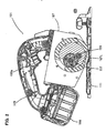
- FIG. 1 is a side view showing an entire circular saw 101 according to this embodiment.
- FIG. 2 is a sectional side view ofthe entire circular saw 101.
- FIG. 3 is a sectional front view ofthe entire circular saw 101.
- the circular saw 101 according to this embodiment includes a base 111 which can be placed on a workpiece (not shown) and moved in a cutting direction, and a circular saw body 103 disposed above the base 111.
- the circular saw body 103 is a feature that corresponds to the "power tool body" according to this invention.
- the circular saw body 103 mainly includes a blade case 104 that covers substantially an upper half of a disc-like blade (saw blade) 113 which is rotated in a vertical plane, a motor housing 105 that houses a driving motor 115, a gear housing 107 that houses a speed change mechanism 117, and a handgrip 109 which is held by a user to operate the circular saw 101.
- the blade 113 and the driving motor 115 are features that correspond to the "tool bit" and the "power source”, respectively, according to this invention.
- the speed change mechanism 117 is now explained with reference to FIGS. 4 and 5 .
- the speed change mechanism 117 is of a parallel three-shaft type having three shafts disposed parallel to each other, i.e. an input shaft 121 which is coaxially connected to a motor shaft 116 of the driving motor 115, an output shaft in the form of a blade mounting shaft 125 onto which the blade 113 is fitted, and an intermediate shaft 123 disposed between the input shaft 121 and the blade mounting shaft 125.
- the speed change mechanism 117 is of the two-stage switching type in which a power transmission path can be automatically switched between a high-speed low-torque path and a low-speed high-torque path according to the magnitude of load applied to the blade 113.
- the intermediate shaft 123 is a feature that corresponds to the "first rotating shaft” and the "upstream shaft”, and the blade mounting shaft 125 corresponds to the "second rotating shaft” and the “output shaft”, according to this invention.
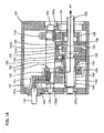
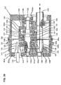
- FIGS. 4 and 5 are developed sectional views of the parallel three-shaft type speed change mechanism 117.
- FIG. 4 shows the state in which the power transmission path is switched to the high-speed low-torque path
- FIG. 5 shows the state in which the power transmission path is switched to the low-speed high-torque path.
- the blade mounting shaft 125 is referred to as the output shaft.
- the speed change mechanism 117 includes a first power transmission path P1 through which torque of the input shaft 121 is transmitted from a pinion gear 131 to the output shaft 125 via a first intermediate gear 132, the intermediate shaft 123, a second intermediate gear 133 and a first driven gear 134, and a second power transmission path P2 through which torque of the input shaft 121 is transmitted from the pinion gear 131 to the output shaft 125 via the first intermediate gear 132, the intermediate shaft 123, a third intermediate gear 135 and a second driven gear 136.
- the gear ratio (speed reduction ratio) between the second intermediate gear 133 and the first driven gear 134 is designed to be lower than the gear ratio (speed reduction ratio) between the third intermediate gear 135 and the second driven gear 136.
- the first power transmission path P1 forms a high-speed low-torque power transmission path
- the second power transmission path P2 forms a low-speed high-torque power transmission path.
- the first and second power transmission paths P1, P2 are shown by bold arrowed line.
- the second intermediate gear 133 and the first driven gear 134 form the "first gear train” according to the invention
- the third intermediate gear 135 and the second driven gear 136 form the "second gear train" according to the invention.
- the input shaft 121, the intermediate shaft 123 and the output shaft 125 in the speed change mechanism 117 are rotatably supported by the gear housing 107 via bearings 121a, 123a, 125a, respectively.
- a drive gear in the form of the pinion gear 131 is integrally formed on the input shaft 121.
- the first intermediate gear 132 and the third intermediate gear 135 are disposed side by side on one end region (on the driving motor 115 side or the left side as viewed in the drawing) of the intermediate shaft 123 and integrated with the intermediate shaft 123 via a common key 137.
- the first intermediate gear 132 is normally engaged with the pinion gear 131
- the third intermediate gear 135 is normally engaged with the second driven gear 136 provided on one end region of the output shaft 125.
- the second intermediate gear 133 is mounted for relative rotation on the other end region (on the blade 113 side or the right side as viewed in the drawing) of the output shaft 125 via a bearing 138 and normally engaged with the first driven gear 134.
- the first driven gear 134 is disposed on the other end region of the output shaft 125 and integrated with the output shaft 125 via a key 139.
- the output shaft 125 or the blade 113 is rotationally driven via the high-speed low-torque first power transmission path P1. Thereafter, when the load applied to the blade 113 reaches a predetermined value as the cutting operation proceeds, it is automatically switched to the low-speed high-torque second power transmission path P2.
- Such switching from the first power transmission path P1 to the second power transmission path P2 is realized by providing a sliding engagement clutch 141 on the intermediate shaft 123 and a one-way clutch 145 on the output shaft 125.
- the sliding engagement clutch 141 and the one-way clutch 145 are features that correspond to the "first and second clutches", respectively, according to the invention.
- FIGS. 6 to 10 The construction ofthe sliding engagement clutch 141 is shown in FIGS. 6 to 10 as well as FIGS. 4 and 5 .
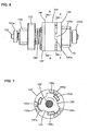
- FIG. 6 is an external view of the sliding engagement clutch 141 and
- FIG. 7 is a sectional view taken along line A-A in FIG. 6 .
- FIG. 8 shows a drive side clutch member 142
- FIG. 9 shows a driven side clutch member 143
- FIG. 10 shows a torque ring 152.
- the sliding engagement clutch 141 mainly includes the drive side clutch member 142 and the driven side clutch member 143 which face each other in the axial direction of the intermediate shaft 123, and a clutch spring 144 which presses and biases the drive side clutch member 142 toward the driven side clutch member 143.
- the drive side clutch member 142 and the driven side clutch member 143 have a plurality of (for example, three) generally trapezoidal cams 142a, 143a, respectively, in the circumferential direction on the respective sides facing each other. Torque is transmitted when the cams 142a, 143a are engaged with each other (see FIGS. 4 and 6 ), while the torque transmission is interrupted when the cams 142a, 143a are disengaged from each other (see FIG. 5 ).
- the drive side clutch member 142 is loosely fitted onto the intermediate shaft 123. Specifically, the drive side clutch member 142 is mounted onto the intermediate shaft 123 such that it can slide with respect to the intermediate shaft 123 in the circumferential direction and the axial direction. The drive side clutch member 142 is rotationally driven via a torque transmission member in the form of the torque ring 152 which is press-fitted onto the intermediate shaft 123. As shown in FIG. 10 , the torque ring 152 has a plurality of (three) torque transmission parts in the form of protrusions 152a which protrude radially outward and are evenly spaced in the circumferential direction.
- a housing space 153 is formed in a side ofthe drive side clutch member 142 on which the cams 142a are formed, and has a shape generally corresponding to the contour of the torque ring 152.
- the torque ring 152 is housed in the housing space 153 such that the torque ring 152 cannot move in the circumferential direction with respect to the drive side clutch member 142.
- Each of the protrusions 152a of the torque ring 152 is engaged with an engagement recess 153a (see FIG. 8 ) of the housing space 153.
- the protrusion 152a pushes a radial wall surface of the drive side clutch member 142 which faces the engagement recess 153a, or a torque transmission surface 153b, in the circumferential direction, so that the drive side clutch member 142 rotates together with the torque ring 152.
- the driven side clutch member 143 is integrated with the second intermediate gear 133.
- the drive side clutch member 142 is biased toward a power transmission position in which the cams 142a are engaged with the cams 143a of the driven side clutch member 143, by an elastic member in the form of a clutch spring 144 comprising a compression coil spring.
- the clutch spring 144 is elastically disposed between the drive side clutch member 142 and the first intermediate gear 132.
- FIG. 11(A) shows the sliding engagement clutch 141 shifting from the power transmission state to the power transmission interrupted state.
- the one-way clutch 145 is activated, so that the power transmission path is switched from the high-speed low-torque first power transmission path P1 to the low-speed high-torque second power transmission path P2.
- the one-way clutch 145 is now explained.
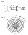
- the construction of the one-way clutch 145 is shown in FIGS. 15 and 16.
- FIG. 15 is a side view showing parts provided on the output shaft 125
- FIG. 16 is a sectional view taken along line C-C in FIG. 15 .
- the one-way clutch 145 mainly includes an outer ring 146 that rotates together with the second driven gear 136, a plurality of needle rollers 147 and springs 148 which are disposed between the outer ring 146 and the output shaft 125.
- the needle rollers 147 are rotatably disposed in cam grooves 146a which are formed in the outer ring 146 at predetermined intervals in the circumferential direction, and biased by the springs 148 toward the position of engagement with cam faces 146b.
- the sliding engagement clutch 141 is held such that the drive side clutch member 142 is biased toward the driven side clutch member 143 by the biasing force of the clutch spring 144. Specifically, it is held in the power transmission state in which the cams 142a, 143a of the clutch members 142, 143 are engaged with each other. In this state, when the driving motor 115 is driven to perform a cutting operation on a workpiece, the torque of the driving motor 115 is transmitted to the output shaft 125 via the first power transmission path P1.
- the blade 113 is rotated at high speed and low torque via the pinion gear 131, the first intermediate gear 132, the intermediate shaft 123, the sliding engagement clutch 141, the second intermediate gear 133, the first driven gear 134 and the output shaft 125.
- the outer ring 146 of the one-way clutch 145 is also rotated via the intermediate shaft 123, the third intermediate gear 135 and the second driven gear 136. As described above, however, the outer ring 146 idles because the output shaft 125 rotates at higher speed than the outer ring 146.
- a cutting operation on a workpiece by the blade 113 starts at high speed and low torque via the first power transmission path P1. Thereafter, when the load applied to the blade 113 reaches a switching set value defined by the clutch spring 144 of the sliding engagement clutch 141, the sliding engagement clutch 141 is shifted to the power transmission interrupted state. Specifically, as shown in FIG. 11(A) , the drive side clutch member 142 is moved away from the driven side clutch member 143 against the biasing force of the clutch spring 144 by components of the force acting upon the drive side clutch member 142 in the longitudinal direction via the cam faces (inclined surfaces) of the cams 142a, 143a, so that the cams 142a, 143a are disengaged from each other.
- the sliding engagement clutch 141 is shifted to the power transmission interrupted state, and when the speed of rotation of the output shaft 125 is reduced to below the speed of rotation of the outer ring 146 of the one-way clutch 145, the needle rollers 147 are engaged between the associated cam faces 146b and the output shaft 125 by the biasing force of the associated springs 148, and drive the output shaft 125 by a wedging action.
- the transmission path of the torque of the driving motor 115 is switched from the first power transmission path P1 to the second power transmission path P2, and the blade 113 is rotated at low speed and high torque which are determined by the gear ratio between the pinion gear 131 and the first intermediate gear 132 and the gear ratio between the third intermediate gear 135 and the second driven gear 136.
- the cutting operation when the load applied to the blade 113 is low, the cutting operation can be performed on the workpiece at high speed and low torque by using the first power transmission path P1 having a low gear ratio.
- the cutting operation when the load applied to the blade 113 is high, the cutting operation can be performed on the workpiece at low speed and high torque by using the second power transmission path P2 having a high gear ratio.
- the driving motor 115 can be prevented from being burnt, and the work rate of cutting on a single charge of the battery 108 can be improved.
- switching from the first power transmission path P1 to the second power transmission path P2 can be made in the state in which the gears in the gear trains forming the speed change mechanism 117 are held engaged with each other, or in which the positions of the gears are fixed. Therefore, speed changing operation can be performed with increased smoothness.
- the load on the sliding engagement clutch 141 can be reduced. Therefore, such a construction is effective in protecting the clutch or improving the durability of the clutch.
- the intermediate shaft 123 is disposed toward the center of the gear housing 107. Therefore, by disposing the sliding engagement clutch 141 which is larger in the radial direction than the one-way clutch 145, on the intermediate shaft 123, the gear housing 107 can be prevented from increasing in size.
- the maximum cutting depth of the circular saw 101 (the amount of protrusion of the lower edge portion of the blade 113 from the underside of the base 111) is defined by contact of a maximum cutting depth control part formed on the gear housing 107 with a stopper on the base 111, which is not shown, when the user depresses the handgrip 109 downward from the state shown in FIG. 2 so that the circular saw body 103 is rotated on a pivot (not shown) provided on the front end portion ofthe base 111. Therefore, for example, if the sliding engagement clutch 141 having a large outside diameter is provided on the output shaft 125, the distance from the center of the output shaft 125 to a lower end surface 107L of the gear housing 107 is increased, which affects the maximum cutting ability.
- the maximum cutting ability is degraded. According to this embodiment, however, by providing the sliding engagement clutch 141 on the intermediate shaft 123, the distance from the output shaft 125 to the lower end surface 107L of the gear housing 107 can be decreased, which does not affect the maximum cutting ability.
- the one-way clutch 145 is provided on the output shaft 125.
- the second driven gear 136 on the output shaft 125 on the speed reduced side has a larger diameter than the third intermediate gear 135 on the intermediate shaft 123. Therefore, by disposing the one-way clutch 145 between the output shaft 125 and the second driven gear 136, a mounting space for the one-way clutch 145 can be easily secured, so that the one-way clutch 145 can be easily mounted.
- the speed change mechanism 117 is provided with a latching mechanism 151 and a reset mechanism Once the sliding engagement clutch 141 is shifted to a power transmission interrupted state, the shifted state is retained by the latching mechanism 151.
- the reset mechanism serves to return it to the initial state or power transmission state after stop of the cutting operation (when the driving motor 115 is stopped).
- the latching mechanism 151 is a feature that corresponds to the "switching retaining mechanism" according to this invention.
- the latching mechanism 151 is now explained mainly with reference to FIGS. 7 , 8 , 10 and 11 .
- the latching mechanism 151 serves to retain the drive side clutch member 142 in the power transmission interrupted position, or particularly in the position in which the cams 142a of the drive side clutch member 142 are separated (opposed with a clearance) from the cams 143a of the driven side clutch member 143.
- the latching mechanism 151 mainly includes the above-described torque ring 152.
- the torque ring 152 is a feature that corresponds to the "latching member" according to this invention.
- an inclined surface 153c inclined upward and forward is formed on the drive side clutch member 142 in a forward region (in the direction of rotation) of each of the engagement recesses 153a with which the protrusions 152a of the torque ring 152 are engaged.
- FIG. 11(A) shows the clutch movement
- FIG. 11(B) shows the movement of the torque ring 152 provided as the latching member.
- the surface of the protrusion 152a which faces the associated inclined surface 153c is configured as an inclined surface or arcuate curved surface.
- the housing space 153 is a feature that corresponds to the "recess" according to this invention.
- the protrusion 152a of the torque ring 152 is slipped out of the associated engagement recess 153a and disengaged from the associated torque transmission surface 153b.
- a difference is caused in the rotation speed between the torque ring 152 and the drive side clutch member 142 to which torque is no longer transmitted. Therefore, the torque ring 152 moves in the circumferential direction with respect to the drive side clutch member 142, and the protrusion 152a of the torque ring 152 climbs on the edge end of the inclined surface 153c (see the second from the top in FIG. 11 ).
- the drive side clutch member 142 is pushed in the longitudinal direction.
- the drive side clutch member 142 is acted upon by a force in a direction (longitudinal direction) in which the cams 142a are separated from the cams 143a of the driven side clutch member 143. Separation of the cams 142a, 143a is assisted by this force. As a result, the load applied to the cam faces of the cams 142a, 143a is lessened, so that wear of the cams 142a, 143a can be reduced, and thus fluctuations of the switching set value defined by the clutch spring 144 can be minimized.
- the torque ring 152 When the drive side clutch member 142 is further retracted and the cams 142a, 143a are disengaged from each other, the torque ring 152 further moves in the circumferential direction with respect to the drive side clutch member 142. Therefore, the protrusion 152a further climbs onto the inclined surface 153c. Specifically, assistance in separation of the cams 142a, 143a by this climbing movement is continued even after disengagement of the cams 142a,143a. Therefore, the drive side clutch member 142 is further moved away from the driven side clutch member 143 so that a clearance is created in the longitudinal direction between the cams 142a, 143a.
- the protrusion 152a climbs on the inclined surface 153c and is engaged with a stopper surface 153d extending upright from the front end of the inclined surface 153c. Thereafter, the torque ring 152 and the drive side clutch member 142 rotate together. This state is shown in FIG. 11(B) on the bottom.
- the torque ring 152 further retracts the drive side clutch member 142 past the power transmission interrupted position in which the cam 142a ofthe drive side clutch member 142 is disengaged from the cam 143a of the driven side clutch member 143, or to an isolated position in which a predetermined clearance is secured in the longitudinal direction between the cams 142a, 143a, and retains it in this isolated position.
- the sliding engagement clutch 141 is shifted to the power transmission interrupted state, it retains the shifted state regardless of the load applied to the blade 113.
- the torque ring 152 is returned (reset) to its initial position, so that the power transmission interrupted state held by the sliding engagement clutch 141 is automatically released.
- the reset mechanism is formed by utilizing the brake of the driving motor 115 and the inertia of the drive side clutch member 142.
- the drive side clutch member 142 is moved to the power transmission position by the biasing force of the clutch spring 144, so that it can be properly made ready for the next cutting operation.
- the speed change mechanism 117 when the blade 113 has a large mass and great inertia, at the time of startup of the driving motor 115, the sliding engagement clutch 141 may malfunction, or particularly shift from the power transmission state to the power transmission interrupted state and cause speed change.
- the speed change mechanism 117 according to this embodiment is provided with a speed change preventing mechanism 161 for preventing speed change at the time of startup of the motor.
- FIG. 12 is a sectional view taken along line B-B in FIG. 6 .
- FIG. 13 is a perspective view of the drive side clutch member 142 as viewed from the clutch spring mounting side.
- FIG. 14 is a perspective view of a stopper 162.
- the speed change preventing mechanism 161 according to this embodiment mainly includes a plurality of (for example, three) stoppers 162 and elastic members in the form of compression coil springs 163 which are radially arranged in the drive side clutch member 142.
- Stopper housing recesses 164 are formed on the clutch spring mounting side (the side opposite from the cam 142a side) of the drive side clutch member 142 and arranged equiangularly in the circumferential direction.
- the stoppers 162 and the compression coil springs 163 are disposed within the stopper housing recesses 164 and can move in the radial direction.
- a radially inner end of each of the stoppers 162 faces the outer circumferential surface of the intermediate shaft 123, and the stopper 162 is pressed and biased toward the intermediate shaft 123 by the associated compression coil spring 163.
- An annular groove 165 is formed in the circumferential direction in a region of the outer circumferential surface of the intermediate shaft 123 which faces the stoppers 162.
- each of the stoppers 162 When the drive side clutch member 142 is placed in the power transmission position, the radially inner end of each of the stoppers 162 enters the annular groove 165 in the outer circumferential surface of the intermediate shaft 123 from the radial direction and is elastically engaged therewith, so that the drive side clutch member 142 is held in the power transmission position. This state is shown in FIGS. 12 and 4 .
- a cover 167 is mounted on the side of the drive side clutch member 142 in order to cover the stoppers 162 and the compression coil springs 163 disposed within the stopper housing recesses 164.
- the cover 167 also serves as a spring receiving member for supporting one end of the clutch spring 144.
- the speed change preventing mechanism 161 is constructed as described above.
- the driving motor 115 is in the stopped state, the sliding engagement clutch 141 is in the power transmission state.
- the stoppers 162 are held in engagement with the annular groove 165 of the intermediate shaft 123. Therefore, at the time of startup of the driving motor 115, the stoppers 162 held in engagement with the annular groove 165 of the intermediate shaft 123 prevent the drive side clutch member 142 from moving in the longitudinal direction, so that the drive side clutch member 142 is held in the power transmission position in which the cams 142a are engaged with the cams 143a of the driven side clutch member 143. In this manner, the sliding engagement clutch 141 can be prevented from malfunctioning at the time of startup of the motor.
- the stoppers 162 When the driving motor 115 is started and the motor speed is increased, however, the stoppers 162 are moved outward against the biasing force of the compression coil spring 163 by centrifugal force acting upon the stoppers 162 which rotate together with the drive side clutch member 142, so that the stoppers 162 are disengaged from the annular groove 163 (see FIG. 5 ). Thus, the stoppers 162 can no longer prevent the drive side clutch member 142 from moving, so that the drive side clutch member 142 is allowed to shift from the power transmission state to the power transmission interrupted state according to the load applied to the blade 113.
- the speed change mechanism 117 does not cause such a malfunction that it causes speed change by inertia of the blade 113 at the time of startup of the driving motor 115. Therefore, the advantage of the speed change mechanism 117 can be fully utilized. Further, the speed change preventing mechanism 161 is particularly effective not only in the circular saw 101 but in a power tool having a tool bit of a great mass, such as a grinder for grinding and polishing and a diamond core drill for drilling a relatively large-diameter hole.
- FIGS. 17 and 18 A second embodiment of the invention is now explained with reference to FIGS. 17 and 18 .
- the sliding engagement clutch 141 is disposed on the output shaft 125 and effects speed change on the output shaft 125.
- this embodiment has the same construction as the above-described first embodiment. Therefore, components shown in FIGS. 17 and 18 are given like numerals as in the first embodiment and will not be described or briefly described.
- FIGS. 17 and 18 are developed sectional views showing the construction of the speed change mechanism 117.
- the sliding engagement clutch 141 is mounted on the output shaft 125.
- the second intermediate gear 133 is fixedly mounted on the intermediate shaft 123 by the key 139, and the first driven gear 134 normally engaged with the second intermediate gear 133 is rotatably supported on the output shaft 125 via the bearing 138.
- the sliding engagement clutch 141 mainly includes the drive side clutch member 142, the driven side clutch member 143 and the clutch spring 144.
- this embodiment is the same as the above-described first embodiment. In this embodiment, however, the direction of transmission of power is opposite to that in the first embodiment in which the sliding engagement clutch 141 is mounted on the intermediate shaft 123.
- the clutch member 143 which rotates together with the first driven gear 134 is on the drive side
- the clutch member 142 which rotates together with the output shaft 125 via the torque ring 152 is on the driven side.
- the clutch spring 144 is disposed between the driven side clutch member 142 and the second driven gear 136 to which the one-way clutch 145 is mounted and biases the driven side clutch member 142 toward the drive side clutch member 143.
- the torque of the driving motor 115 is transmitted to the blade 113 via the first power transmission path P 1 which is formed by the pinion gear 131 of the input shaft 121, the first intermediate gear 132, the intermediate shaft 123, the second intermediate gear 133, the first driven gear 134, the sliding engagement clutch 141 and the output shaft 125. Then the blade 113 is rotationally driven at high speed and low torque. This state is shown in FIG. 17 .
- the driven side clutch member 142 When a load exceeding a switching set value defmed by the clutch spring 144 is applied to the blade 113, the driven side clutch member 142 is moved from the power transmission position to the power transmission interrupted position against the biasing force of the clutch spring 144. Thus, the cams 142a of the driven side clutch member 142 are disengaged from the cams 143a of the drive side clutch member 143. As a result, the torque ofthe driving motor 115 is transmitted to the blade 113 via the second power transmission path P2 which is formed by the pinion gear 131 of the input shaft 121, the first intermediate gear 132, the intermediate shaft 123, the third intermediate gear 135, the second driven gear 136, the one-way clutch 145 and the output shaft 125. Then the blade 113 is rotated at low speed and high torque. This state is shown in FIG. 18 .
- the power transmission path can be switched from the first power transmission path P1 to the second power transmission path P2 in the state in which the gears in the gear trains forming the speed change mechanism 117 are held engaged with each other, or in which the positions of the gears are fixed. Therefore, speed changing operation can be performed with increased smoothness.
- FIGS. 19 to 21 A third embodiment of the invention is now explained with reference to FIGS. 19 to 21 .
- This embodiment is a modification relating to a latching mechanism 251 by which, once the sliding engagement clutch 141 is shifted to a power transmission interrupted state, the shifted state is retained.
- the second embodiment has the same construction as the above-described first embodiment except for the latching mechanism 251. Therefore, components of the speed change mechanism 117 which are not related to the latching mechanism shown in FIGS. 19 and 20 are given like numerals as in the first embodiment and will not be described or briefly described.
- FIGS. 19 and 20 are developed sectional views, and FIG. 21 is an enlarged view of part D of FIG. 19 .
- the latching mechanism 251 is arranged on the gear housing 107 and mainly includes a ball 252, a slide block 253 and a compression coil spring 254.
- the ball 252 and the compression coil spring 254 are features that correspond to the "latching member” and the "biasing member", respectively, according to this invention.
- a latch mounting region 107a is provided on the gear housing 107 in order to mount the latching mechanism 251 such that the latching mechanism 251 can be moved closer to the sliding engagement clutch 141.
- the ball 252 is inserted in a ball holding hole 225 which is formed radially through the latch mounting region 107a ofthe gear housing 107 in an area of the latch mounting region 107a which faces the outer circumferential surface of the drive side clutch member 142 of the sliding engagement clutch 141.
- the ball 252 is allowed to move in a direction transverse to the longitudinal direction of the drive side clutch member 142 (the axial direction of the intermediate shaft 123).
- the compression coil spring 254 has a larger spring constant than the clutch spring 144.
- the ball 252 is biased from the outside to the inside of the latch mounting region 107a via a slide block 253 by the compression coil spring 254 and elastically pressed in the radial direction against the outer surface of the drive side clutch member 142.
- the drive side clutch member 142 has a stepped cylindrical shape having a smaller-diameter portion facing the driven side clutch member 143 and a larger-diameter portion facing away from the driven side clutch member 143.
- a connecting region between the smaller-diameter portion and the larger-diameter portion is formed by a concave curved surface 256.
- the curved surface 256 may be changed to an inclined surface.
- the curved surface 256 is a feature that corresponds to the "engagement part" according to this invention.
- the ball 252 is pressed radially inward by the compression coil spring 254 and thus applies a force to the drive side clutch member 142 via the curved surface 256 in a direction (longitudinal direction) in which the cams 142a are separated from the cams 143a of the driven side clutch member 143, thereby assisting in separation of the cams 142a, 143a.
- the width (length in the longitudinal direction) of the curved surface 256 is set such that this assistance is started midway through the retracting movement of the drive side clutch member 142 and continued until the cams 142a, 143a are disengaged from each other and a predetermined clearance is created between the cams 142a, 143a.
- the slide block 253 is mounted on the outer surface of the latch mounting region 107a such that it can slide in a direction parallel to the longitudinal direction of the drive side clutch member 142, and the slide block 253 is biased by the compression coil spring 254.
- the slide block 253 can press the ball 252 toward the drive side clutch member 142 via a contact surface of the slide block 253 in contact with the outer wall surface of the latch mounting region 107a, or a slide surface 253a.
- a notch 253b is further formed in a front end portion of the slide surface 253a of the slide block 253 (on the side facing away from the compression coil spring 254) and serves to release the ball 252 pressed by the slide block 253.
- the latching mechanism 251 is constructed as described above. Therefore, under high-speed and low-torque driving conditions in which the torque of the driving motor 115 is transmitted to the blade 113 via the first power transmission path P1 of the speed change mechanism 117, the latching mechanism 251 is held in the initial position.
- the drive side clutch member 142 is retracted (by engagement of the inclined surfaces of the cams 142a, 143a in the same manner as in the first embodiment) to the power transmission interrupted position in which it is separated from the driven side clutch member 143.
- the sliding engagement clutch 141 is shifted to the power transmission interrupted state, so that the torque transmission path to the blade 113 is switched from the first power transmission path P1 to the second power transmission path P2.
- the ball 252 approaches the front end of the curved surface 256 in the retracting direction when the cams 142a of the drive side clutch member 142 reach the verge of separation from the cams 143a of the driven side clutch member 143 (for example, the position shown in the second or the third from the top in FIG. 11(A) ). Then the ball 252 acted upon by the biasing force of the compression coil spring 254 via the slide block 253 presses the curved surface 256 from the radial direction, and by components of this pressing force acting upon the curved surface 256 in the longitudinal direction, the ball 252 further retracts the drive side clutch member 142 against the biasing force of the clutch spring 144.
- the drive side clutch member 142 is further retracted to an isolated position in which the drive side clutch member 142 is further separated from the driven side clutch member 143 past the power transmission interrupted position in which the cams 142a, 143a are disengaged from each other.
- a certain clearance can be created in the longitudinal direction between the cams 142a of the drive side clutch member 142 and the cams 143a of the driven side clutch member 143 (see the bottom in FIG. 11(A) ).
- the ball 252 held in engagement with the curved surface 256 is held in contact with the slide surface 253a of the slide block 253 and thus prevented from moving radially outward, so that the sliding engagement clutch 141 is reliably held in the power transmission interrupted state.
- the slide block 253 is slid against the biasing force of the compression coil spring 254 with user's finger so that the ball 252 locked by the slide surface 253a is released.
- the torque ring 152 disposed between the drive side clutch member 142 and the intermediate shaft 123 is designed to serve only as a torque transmitting member.
- the latching mechanism 251 As described above, by provision of the latching mechanism 251 according to this embodiment, once the sliding engagement clutch 141 is shifted to the power transmission interrupted state, it can retain the power transmission interrupted state regardless of the load applied to the blade 113. Therefore, even if the load applied to the blade 113 fluctuates around the switching set value defined by the clutch spring 144, stable cutting operation can be realized at low speed and high torque by using the second power transmission path P2. Further, a certain clearance can be secured in the longitudinal direction between the cams 142a, 143a, so that a reliable power transmission interrupted state can be obtained. Thus, noise and vibration can be prevented from being caused by interference between the cams 142a, 143a.
- the speed change mechanism 117 is described as being of a parallel three-shaft type, but it may be of a two-shaft type having two parallel shafts, or an input shaft and an output shaft. Further, it may be of a type in which the one-way clutch 145 is disposed on the intermediate shaft 123 side. Further, in this embodiment, the battery-powered circular saw 101 is described as a representative example of a power tool according to the invention, but it is not limited to this.
- This invention can be applied to an AC-powered circular saw as well as the battery-powered circular saw, and to a tabletop circular saw and a tabletop slide circular saw which perform a cutting operation on a workpiece placed on a table of a base, as well as the hand-held circular saw as shown in the drawings, and also to a circular saw for woodworking or metalworking. It can also be applied to a cutting tool other than a circular saw, such as an electric cutter, and a cutting tool having a reciprocating tool bit, such as a reciprocating saw and a jigsaw.
- a power tool such as a sander and a grinder which perform grinding or polishing operation on a workpiece by a rotating sanding disc or grinding wheel, a driver and a wrench for tightening operation, various kinds of drills for drilling operation, and a hedge trimmer for trimming a hedge by reciprocating upper and lower blades in opposite directions.
- a power tool such as a sander and a diamond core drill, in which a load applied to the tool bit varies in one power tool with variations in the size of the tool bit used or with variations in workpieces.
- the power tool wherein an inclined surface is further formed on the side of the sliding side clutch member and faces a front region of the recess in the rotating direction, and when the sliding side clutch member is moved to the power transmission interrupted position, the latching member is moved out of the recess by the movement of the sliding side clutch member and climbs on the inclined surface due to a difference in the rotation speed between the sliding side clutch member and the latching member which is caused by the movement of the latching member out of the recess, thereby further moving the sliding side clutch member from the power transmission interrupted position to an isolated position in which the sliding side clutch member is further separated from an opposed clutch member and retaining the sliding side clutch member in the isolated position.
- the stopper 162 pressed against the side wall of the annular groove 165 is prevented from being disengaged from the annular groove 165 and held in the engaged state by friction acting upon a contact surface 162a which gets in contact with the side wall ofthe stopper housing recess 164 of the drive side clutch member 142 and a contact surface 162b which gets in contact with the side wall of the annular groove 165. Thereafter, when the load on the driven side is reduced as the rotation speed increases and the drive side clutch member 142 is moved back toward the driven side clutch member 143 by the biasing force ofthe clutch spring 144, so that the above-described friction is no longer produced, as shown in FIG.
- FIG. 22(B) shows the stop side clutch member 142 shifted from the power transmission state to the power transmission interrupted state.
- the stopper 162 can be held in engagement with the annular groove 165 by utilizing friction applied to the side of the stopper 162 at the time of startup of the driving motor 115. Therefore, speed change at the time of startup of the motor can be prevented even if the compression coil spring 163 for biasing the stopper 162 onto the annular groove 165 comprises a spring having a weak biasing force by which the stopper 162 is retained at most so as not to be disengaged from the annular groove 165.
- FIG. 23 shows modification 1 relating to speed change prevention at the time of startup of the motor by using the stopper 162.
- Modification 1 is designed to provide more secure speed change prevention by the stopper 162.
- One side of the stopper 162 (which comes in contact with the side wall of the annular groove 165 when the drive side clutch member 142 is moved away from the driven side clutch member 143) and the side wall of the annular groove 165 which faces the one side of the stopper 162 have respective inclined surfaces, so that the stopper 162 has an undercut 162c formed as an interference region.
- the annular groove 165 is formed to have such a width (length in the longitudinal direction) that the undercut 162c of the stopper 162 can be allowed to be disengaged from the annular groove 165.
- the width of the annular groove 165 is set such that the stopper 162 engaged with the annular groove 165 is allowed to move with respect to the annular groove 165 in the longitudinal direction within the range in which the drive side clutch member 142 is held in engagement with the driven side clutch member 143.
- FIG. 24 shows modification 2 relating to speed change prevention at the time of startup of the motor by using the stopper 162.
- Modification 2 is designed to provide further more secure speed change prevention by the stopper 162.
- a generally L-shaped protrusion 162d having a surface generally parallel to the axis of the intermediate shaft 123 is formed on one side of the stopper 162 (which comes in contact with the side wall of the annular groove 165 when the drive side clutch member 142 is moved away from the driven side clutch member 143), and a recess 165b for receiving the protrusion 162d is formed in the side wall of the annular groove 165 which faces the one side of the stopper 162.
- the stopper 162 is formed with an undercut. Therefore, in modification 2, like in modification 1, the annular groove 165 is formed to have such a width (length in the longitudinal direction) that the protrusion 162d of the stopper 162 can be allowed to be disengaged from the annular groove 165.
- the protrusion 162d of the stopper 162 is engaged in the recess 165b of the annular groove 165 by the driven side load. Thereafter, when the load on the driven side is reduced and the protrusion 162d of the stopper 162 is disengaged from the recess 165b of the annular groove 165 as the drive side clutch member 142 is moved toward the driven side clutch member 143 by the clutch spring 144, the stopper 162 is moved out ofthe annular groove 165 by centrifugal force.
- FIG. 24(B) shows the state of the drive side clutch member 142 shifted from the power transmission state to the power transmission interrupted state.
- This embodiment is a modification relating to the speed change preventing mechanism 161 which prevents the torque transmission path of the speed change mechanism 117 from switching by inertia of the blade 113 at rest.
- This embodiment is of an electromagnetic solenoid type and constructed such that, for example, a microcomputer is executed to activate an electromagnetic solenoid to release the speed change prevention after a lapse of a predetermined time.
- the speed change preventing mechanism 161 according to this embodiment mainly includes an electromagnetic solenoid 171 and a stopper 172 which is activated by the electromagnetic solenoid 171.
- the electromagnetic solenoid 171 is mounted, for example, on the gear housing 107.
- the stopper 172 is linearly moved by the electromagnetic solenoid 171.
- the stopper 172 protrudes radially inward of the drive side clutch member 142 by the biasing force of a spring which is not shown, and engages (contacts) with a side of the drive side clutch member 142 on the clutch spring 144 side which is held in the power transmission position by the biasing force of the clutch spring 144, or with the side of the cover 167.
- the drive side clutch member 142 is prevented from moving from the power transmission position to the power transmission interrupted position. This state is shown in FIG. 25 .
- a microcomputer is executed to energize (drive) the electromagnetic solenoid 171 so that the stopper 172 is moved radially outward of the drive side clutch member 142 and disengaged from the cover 167.
- This state is shown in FIG. 26 .
- the drive side clutch member 142 is allowed to shift from the power transmission state to the power transmission interrupted state according to the load applied to the blade 113.
- This embodiment is described as being constructed such that the electromagnetic solenoid 171 is energized when a predetermined time elapses since the driving motor 115 is started, but it may be constructed such that a sensor for detecting the rotation speed of the driving motor 115 is provided and the electromagnetic solenoid 171 is energized based on a detected signal indicating that the rotation speed of the driving motor 115 is increased to a rotation speed.
- the speed change mechanism 117 can be prevented from causing such a malfunction that it switches from the first power transmission path P1 to the second power transmission path P2 by inertia of the blade 113 at the time of startup of the driving motor 115.
- FIGS. 27 and 28 A sixth embodiment of the invention is now explained with reference to FIGS. 27 and 28 .
- This embodiment is a further modification relating to the speed change preventing mechanism 161.
- a motor control circuit 175 for controlling the driving motor 115 has a soft starting function, so that the output shaft 125 (the blade 113) is slowly rotated at the time of startup of the driving motor 115 and thereby the inertial torque at the time of startup is reduced.
- FIG. 27 shows the motor control circuit 175 which allows soft starting of the driving motor 115.
- the motor control circuit 175 is a feature that corresponds to the "motor control device" according to this invention.
- the motor control circuit 175 mainly includes a direct current power source (battery 108), a starting switch 176 for directing the startup ofthe driving motor 115, a control section 177, and a switching element 178 (an FET transistor is used in this embodiment, but the switching element is not limited to this) for controlling the power supply to the driving motor 115.
- a direct current power source battery 108
- a starting switch 176 for directing the startup ofthe driving motor 115
- control section 177 for controlling the power supply to the driving motor 115.
- a switching element 178 an FET transistor is used in this embodiment, but the switching element is not limited to this
- the starting switch 176 is turned on by depressing the trigger 109a.
- the control section 177 starts operating and controls to gradually increase the voltage applied to a control terminal (a gate terminal of the FET transistor in this embodiment) of the switching element 178.
- the control section 177 controls to gradually increase time "T on" of voltage application to the control terminal of the switching element 178, so that the amount of current passing through the driving motor 115 gradually increases. Therefore, when the starting switch 176 is turned on, the rotation speed of the driving motor 115 gradually increases, and after a lapse of a predetermined time, it reaches a specified speed.
- the time "T on" of application of voltage to the control terminal of the switching element 178 is maintained at a time appropriate to the specified speed.
- a method of soft starting the driving motor 115 is not limited to such a method.
- the inertial torque of the tool bit in the form of the blade 113 can be reduced at the time of startup of the driving motor 115, so that the speed change mechanism 117 can be prevented from switching from the first power transmission path P1 to the second power transmission path P2.
- the speed change mechanism 117 is described as being of a parallel three-shaft type, but it may be of a two-shaft type having two parallel shafts, or an input shaft and an output shaft. Further, the one-way clutch 145 may be disposed on the intermediate shaft 123 side. Further, in this embodiment, the battery-powered circular saw 101 is described as a representative example of a power tool according to the invention, but it is not limited to this.
- This invention can also be applied to an AC-powered circular saw instead of the battery-powered circular saw, or to a tabletop circular saw and a tabletop slide circular saw which perform a cutting operation on a workpiece placed on a table on a base, instead of the hand-held circular saw as shown in the drawings, and also to a circular saw for woodworking or metalworking. It can also be applied to cutting tools other than circular saws, such as an electric cutter, and a cutting tool having a reciprocating tool bit, such as a reciprocating saw and a jigsaw.
- a power tool such as a sander and a grinder which perform grinding or polishing operation on a workpiece by a rotating sanding disc or grinding wheel, a driver and a wrench for tightening operation, various kinds ofdrills for drilling operation, and a hedge trimmer for trimming a hedge by reciprocating upper and lower blades in opposite directions.
- a power tool such as a sander and a diamond core drill, in which a load applied to the tool bit varies in one power tool, for example, with variations in the size of the tool bit used or with variations in workpieces.
- the latching mechanism 151 is provided such that, once the sliding engagement clutch 141 is shifted to a power transmission interrupted state, the shifted state is retained by the latching mechanism 151, but it may be changed to a construction not having the latching mechanism 151.
- the power tool wherein the engagement part comprises an annular groove formed all around the first or second rotating shaft, the annular groove has such a width that the movement preventing member inserted in the annular groove from radially outward is allowed to move with respect to the annular groove in the longitudinal direction of the rotating shaft, and the movement preventing member has an interference region which is engaged with a side wall of the annular groove via a surface of the movement preventing member formed in a direction transverse to the longitudinal direction, at the time of startup of the power source, and thereby interferes with movement of the movement preventing member out of the annular groove.”
- the interference region on the movement preventing member prevention of speed change at the time of startup can be further ensured.
- the power tool wherein, when the sliding side clutch member is moved to the power transmission position after the power source is started, the movement preventing member is moved together with the clutch member in the longitudinal direction so that the interference region is disengaged from the side wall of the annular groove.
- the speed change mechanism 117 has a mode switching mechanism 181 for switching (selecting) the speed change mode.
- the mode switching mechanism 181 is a feature that corresponds to the "mode switching mechanism” according to this invention.
- the mode switching mechanism 181 can switch according to the load applied to the blade 113 among automatic transmission mode in which the torque transmission path is automatically switched from the first power transmission path P1 to the second power transmission path P2, high speed mode in which the torque transmission path is fixed (limited) to the first power transmission path P1, and low speed mode in which the torque transmission path is fixed (limited) to the second power transmission path P2.
- the automatic transmission mode, the high speed mode and the low speed mode are features that correspond to the "first transmission mode", the "second transmission mode” and the "third transmission mode", respectively, according to this invention.
- FIG. 31 is an external view showing the mode switching mechanism 181, and FIGS. 32 to 34 are developed sectional views thereof.
- the gear housing 107 has a generally cylindrical inner housing 107A, and the above-described speed change mechanism 117 is housed within the inner housing 107A (see FIGS. 2 and 3 ).
- the inner housing 107A is constructed such that its longitudinal direction is parallel to the axial direction of the intermediate shaft 123 in the speed change mechanism 117 and thus to the longitudinal direction of the sliding engagement clutch 141.
- the mode switching mechanism 181 is mounted to the inner housing 107A.
- the mode switching mechanism 181 is substantially designed such that the sliding engagement clutch 141 can be shifted among automatic transmission mode in which it is automatically shifted between the power transmission state and the power transmission interrupted state according to the load applied to the blade 113, high speed mode in which it is fixed in the power transmission state regardless of the magnitude ofthe load, and low speed mode in which it is fixed in the power transmission interrupted state regardless of the magnitude of the load.
- the mode switching mechanism 181 mainly includes a mode switching sleeve 182 which is fitted onto the inner housing 107A such that it can rotate in the circumferential direction, and a plurality of (two in this embodiment) rod-like operating members 183 mounted to the mode switching sleeve 182.
- a single (or possibly more) guide groove 107b is formed in the outer circumferential surface of the inner housing 107A.
- a ridge 182a is formed in the inner circumferential surface of the mode switching sleeve 182 and engaged with the guide groove 107b of the inner housing 107A, so that the mode switching sleeve 182 is prevented from moving in the longitudinal direction with respect to the inner housing 107A and in this state it can rotate around its longitudinal axis.
- the mode switching sleeve 182 can be turned by a user.
- the mode switching sleeve 182 may be constructed, for example, such that the mode switching sleeve 182 is directly operated by user's finger through an opening formed in the gear housing 107, or such that it is operated via a mode switching handle which is integrally formed with the mode switching sleeve 182 and exposed to the outside through an opening of the gear housing 107.
- spiral slots (lead grooves) 182b corresponding in number to the operating members 183 are formed in the mode switching sleeve 182 on the same circumference and have a predetermined length in the circumferential direction.
- One axial end (proximal end) of each of the operating members 183 is slidably engaged in each of the slots 182b.
- the operating member 183 radially extends through a longitudinally extending slot 107c formed through the inner housing 107A and toward the middle of the intermediate shaft 123 within the inner housing 107A. Specifically, the operating member 183 is prevented from moving in the circumferential direction by the slot 107c, and in this state, it is allowed to move in the longitudinal direction along the slot 107c.
- the mode switching sleeve 182 when the mode switching sleeve 182 is turned in one direction or the other direction, the operating member 183 slidably engaged in the associated slot 182b moves in one or the other longitudinal direction along the slot 107c of the inner housing 107A.
- the operating conditions of the engagement clutch 141 are shifted.
- the position of the rotating end of the mode switching sleeve 182 turned in a direction LO in FIG. 31 is defined as a position of low speed mode
- the rotating end of the mode switching sleeve 182 turned in a direction HI is defined as a position of high speed mode
- an intermediate position between the two positions is defined as a position of automatic transmission mode.
- the distal end of the operating member 183 is inserted between the side of a spring receiving ring 184 for receiving one end of the clutch spring 144 and the side of the cover 167 fixed to the drive side clutch member 142.
- a cylindrical portion 184a is formed in the middle of the spring receiving ring 184 and protrudes in the longitudinal direction.
- the cylindrical portion 184a of the spring receiving ring 184 is loosely fitted onto a cylindrical portion 167a formed in the middle of the cover 167 and can move in the longitudinal direction with respect to the cylindrical portion 167a. Further, the end surface of the cylindrical portion 184a is in contact with the side of the cover 167.
- the biasing force of the clutch spring 144 is applied to the side of the drive side clutch member 142 via the cover 167.
- a predetermined space is formed between the side of the spring receiving ring 184 and the side of the cover 167 which face each other, and the distal end of the operating member 183 is inserted in the space.
- the mode switching mechanism 181 is constructed as described above. Therefore, when the mode switching sleeve 182 is placed, for example, in the position of automatic transmission mode, the distal end of the operating member 183 is moved toward the side of the spring receiving ring 184 and away from the side of the cover 167.
- the distance between the distal end of the operating member 183 and the side of the cover 167 in the longitudinal direction is set such that the drive side clutch member 142 can be disengaged from the driven side clutch member 143, or such that the cams 142a of the drive side clutch member 142 are allowed to be separated from the cams 143a of the driven side clutch member 143. This state is shown in FIGS. 29 and 30 .
- the sliding engagement clutch 141 can be operated as usual. Therefore, during operation on a workpiece by the circular saw 101, the power transmission path can be automatically switched according to the load applied to the blade 113.
- the distal end of the operating member 183 comes in contact with the side ofthe cover 167 ofthe drive side clutch member 142 placed in the power transmission position.
- This state is shown in FIG. 32 .
- the operating member 183 prevents the drive side clutch member 142 from moving in the clutch releasing direction, so that the sliding engagement clutch 141 is continuously held in the engaged state regardless of fluctuations of the load applied to the blade 113. Therefore, as described above, the torque of the driving motor 115 is transmitted to the blade 113 via the first power transmission path P1 passing through the sliding engagement clutch 141.
- the speed change mechanism 117 is fixed to the first power transmission path P1, and in this state, the blade 113 can be driven at high speed and low torque.
- the mode of the speed change mechanism 117 can be appropriately selected according to the thickness (cutting depth) or hardness of the workpiece, among the high speed mode in which the blade 113 is driven at high speed and low torque, the low speed mode in which it is driven at low speed and high torque, and the automatic transmission mode in which the transmission path is automatically switched between the high-speed and low-torque path and the low-speed and high-torque path.
- the mode can be selected in accordance with the purpose, so that the convenience can be improved.
- FIG. 35 is an external view showing the mode switching mechanism 181 and a speed-change torque adjusting mechanism 191
- FIG. 36 is a developed sectional view thereof.
- the speed-change torque adjusting mechanism 191 is provided which allows the user to arbitrarily adjust a switching set value for speed change (speed-change torque value) at which switching from the first power transmission path P1 to the second power transmission path P2 is effected.
- this embodiment has the same construction as the above-described first embodiment. Therefore, components shown in FIGS. 35 and 36 are given like numerals as in the first embodiment and will not be described or briefly described.
- the speed-change torque adjusting mechanism 191 is disposed in juxtaposition with the above-described mode switching mechanism 181, and it functions when the automatic transmission mode is selected by the mode switching mechanism 181.
- the speed-change torque adjusting mechanism 191 is a feature that corresponds to the "switching set value adjusting mechanism" according to this invention.
- the speed-change torque adjusting mechanism 191 is substantially designed to adjust the biasing force of a spring of the sliding engagement clutch 141 which defines the switching set value.
- an auxiliary clutch spring 194 is further provided, and the biasing force of the auxiliary clutch spring 194 can be adjusted.
- the speed-change torque adjusting mechanism 191 mainly includes a speed-change torque adjusting sleeve 192, and a spring receiving member 193 for adjusting the biasing force which is mounted to the speed-change torque adjusting sleeve 192.
- the speed-change torque adjusting sleeve 192 and the spring receiving member 193 are features that correspond to the "adjusting member" according to this invention.
- the speed-change torque adjusting sleeve 192 is fitted onto the inner housing 107A such that it is prevented from moving in the longitudinal direction via a ridge 192a engaged in a guide groove 107d formed in the inner housing 107A and in this state it can rotate around its longitudinal axis.
- the spring receiving member 193 includes a spring receiving disc 193a which serves to receive one end ofthe auxiliary clutch spring 194 and a plurality of (two in this embodiment) arms 193b extending radially outward from the spring receiving disc 193a.
- each of the arms 193b extends through a longitudinally extending slot 107e formed through the inner housing 107A and is slidably engaged in each of spiral slots (lead grooves) 192b formed in the speed-change torque adjusting sleeve 192. Therefore, when the speed-change torque adjusting sleeve 192 is rotated in one direction or the other direction, the spring receiving member 193 slidably engaged in the associated slot 192b moves in one or the other longitudinal direction along the slot 107e of the inner housing 107A. By utilizing this movement (displacement) of the spring receiving member 193 in the longitudinal direction, the biasing force of the auxiliary clutch spring 194 is adjusted.
- the auxiliary clutch spring 194 is disposed between the spring receiving disc 193a of the spring receiving member 193 and the spring receiving ring 184 and biases the drive side clutch member 142 toward the power transmission position via the spring receiving ring 184. Further, it is constructed such that the speed-change torque adjusting sleeve 192 can be turned in the same manner as the mode switching sleeve 182.
- the speed-change torque adjusting mechanism 191 is constructed as described above. Therefore, when the automatic transmission mode is selected by the mode switching mechanism 181 and the speed-change torque adjusting sleeve 192 is turned in a direction D in FIG. 35 , the spring receiving member 193 moves away from the spring receiving ring 184 so that the biasing force of the auxiliary clutch spring 194 is reduced. When the speed-change torque adjusting sleeve 192 is turned in a direction E in FIG. 35 , the spring receiving member 193 moves toward the spring receiving ring 184 so that the biasing force of the auxiliary clutch spring 194 is increased.
- the user can arbitrarily adjust the switching set value for speed change, at which switching from the first power transmission path P1 to the second power transmission path P2 is effected, by adjusting the biasing force of the auxiliary clutch spring 194 of the sliding engagement clutch 141.
- the speed-change torque adjusting sleeve 192 is adjusted by turning like a screw via the guide groove 107d.
Landscapes
- Engineering & Computer Science (AREA)
- Mechanical Engineering (AREA)
- Drilling And Boring (AREA)
- Mechanical Operated Clutches (AREA)
- Sawing (AREA)
Claims (9)
- Outil motorisé comprenant une source d'énergie (115), un mécanisme de changement de vitesse (117) et un foret d'outil (113) qui est entraîné par la source d'énergie (115) via le mécanisme de changement de vitesse (117) de manière à effectuer une opération prédéterminée, dans lequel :le mécanisme de changement de vitesse (117) comprend un premier et un second arbre rotatif (123, 125) et un premier et un second train d'engrenage (133, 134, 135, 136), le premier et le second arbre rotatif (123, 125) étant disposés parallèlement l'un à l'autre, le premier et le second train d'engrenage (133, 134, 135, 136) ayant différents rapports d'engrenage et chacun ayant une combinaison d'une roue dentée menante (133, 135) et d'une roue dentée menée (134, 136) sous la forme d'une seule unité, qui sont engagées l'une avec l'autre et transmettent le couple du premier arbre rotatif (123) au second arbre rotatif (125), dans lequel un trajet de transmission de couple via le premier train d'engrenage (133, 134) est défini comme premier trajet de transmission d'énergie (P1) et un trajet de transmission de couple via le second train d'engrenage (135, 136) est défini comme second trajet de transmission d'énergie (P2), dans lequel le mécanisme de changement de vitesse comprend en outre un premier embrayage (141) qui permet et interrompt la transmission d'énergie sur le premier trajet de transmission d'énergie (P1) et un second embrayage (145) qui permet et interrompt la transmission d'énergie sur le second trajet de transmission d'énergie (P2), etle trajet de transmission d'énergie est commuté entre le premier et le second trajet de transmission d'énergie (P1, P2), tandis que le premier et le second train d'engrenage (133, 134, 135, 136) sont maintenus engagés, en déplaçant le premier et le second embrayage (141, 145) entre l'état de transmission d'énergie et l'état interrompu de transmission d'énergie, caractérisé en ce que le premier et le second embrayage sont déplacés selon une charge appliquée au foret d'outil (113), etle mécanisme de changement de vitesse (117) comprend un mécanisme de retenue de commutation (151, 251) et, lorsque le trajet de transmission d'énergie est commuté entre le premier et le second trajet de transmission d'énergie (P1, P2), le mécanisme de retenue de commutation (151, 251) retient l'état déplacé jusqu'à ce que la source d'énergie (115) soit arrêtée.
- Outil motorisé selon la revendication 1, dans
lequel :au moins l'un des premier et second embrayages (141, 145) comprend un embrayage à engagement coulissant (141) comprenant un élément d'embrayage côté menant (142) et un élément d'embrayage côté mené (143) qui sont opposés l'un à l'autre sur le premier ou le second arbre rotatif (123, 125) et l'un de l'élément d'embrayage côté menant (142) et de l'élément d'embrayage côté mené (143) est à même de coulisser dans une direction longitudinale entre une position de transmission d'énergie, dans laquelle les éléments d'embrayage (142, 143) sont placés dans l'état de transmission d'énergie par engagement mutuel, et une position interrompue de transmission d'énergie, dans laquelle les éléments d'embrayage (142, 143) sont placés dans l'état interrompu de transmission d'énergie par dégagement mutuel, etle mécanisme de retenue de commutation (151, 251) comprend un élément de verrouillage (152, 252) et, lorsque l'élément d'embrayage côté menant (142) ou l'élément d'embrayage côté mené (143) est déplacé dans la position interrompue de transmission d'énergie, l'élément de verrouillage (152, 252) est engagé sur l'élément d'embrayage côté coulissant déplacé (142, 143) et retient de la sorte l'élément d'embrayage côté coulissant (142, 143) dans l'état interrompu de transmission d'énergie. - Outil motorisé selon la revendication 2, dans lequel :un évidement (153) est formé dans un côté de l'élément d'embrayage côté coulissant (142, 143) etl'élément de verrouillage (152) est fixé au premier ou au second arbre rotatif (123, 125) et logé dans l'évidement (153) de sorte que l'élément de verrouillage (152) ne puisse se déplacer dans une direction circonférentielle par rapport à l'évidement (153) et transmette de la sorte un couple entre le premier ou le second arbre rotatif (123, 125) et l'élément d'embrayage côté coulissant (142, 143) et que, lorsque l'élément d'embrayage côté coulissant (142, 143) est déplacé à l'état interrompu de transmission d'énergie, l'élément de verrouillage (152) soit déplacé hors de l'évidement (153) par le mouvement de l'élément d'embrayage côté coulissant (142, 143) et déplacé par rapport à l'élément d'embrayage côté coulissant (142, 143) dans un sens de rotation dû à une différence de la vitesse de rotation entre l'élément d'embrayage côté coulissant (142, 143) et l'élément de verrouillage (152), qui est provoquée par le mouvement hors de l'évidement (153), et donc engagé sur un côté de l'élément d'embrayage côté coulissant (142, 143), retenant de la sorte l'élément d'embrayage côté coulissant (142, 143) dans la position interrompue de transmission d'énergie.
- Outil motorisé selon la revendication 2, comprenant en outre un boîtier d'engrenage (107) qui abrite le mécanisme de changement de vitesse (117), dans lequel :une partie d'engagement (256) est formée sur une surface circonférentielle externe de l'élément d'embrayage côté coulissant (142, 143), etle mécanisme de retenue de commutation (151) comprend l'élément de verrouillage (252) qui est disposé de manière à être radialement mobile dans le boîtier d'engrenage (107) et vient en contact avec la surface circonférentielle externe de l'élément d'embrayage côté coulissant (142, 143) à partir de la direction radiale, et un élément de sollicitation (254) qui presse l'élément de verrouillage (252) dans une direction d'engagement avec l'élément d'embrayage côté coulissant (142, 143) et, lorsque l'élément d'embrayage côté coulissant (142, 143) est déplacé dans la direction interrompue de transmission d'énergie, l'élément de verrouillage (252) est engagé sur la partie d'engagement (256) et retient de la sorte l'élément d'embrayage côté coulissant déplacé (142, 143) dans la position interrompue de transmission d'énergie.
- Outil motorisé selon l'une quelconque des revendications 1 à 3, comprenant en outre un mécanisme de remise à zéro qui renvoie le mécanisme de retenue de commutation (151, 252) dans une position initiale lorsque la source d'énergie est arrêtée.
- Outil motorisé selon la revendication 3, dans lequel, lorsqu'un frein est appliqué à la source d'énergie (115) pour arrêter la source d'énergie, l'élément de verrouillage (152) est renvoyé à l'évidement (153) en raison d'une différence de la vitesse de rotation qui est provoquée entre l'élément d'embrayage côté coulissant (142, 143) et l'élément de verrouillage (152).
- Outil motorisé selon l'une quelconque des revendications 1 à 6, comprenant en outre un corps d'outil motorisé (103) qui abrite la source d'énergie (115) et le mécanisme de changement de vitesse (117), et une base (111) qui est disposée en dessous du corps d'outil motorisé (103) et peut être placée sur une pièce à traiter, dans lequel le foret d'outil (113) comprend une lame de scie (113) qui est entraînée en rotation via le mécanisme de changement de vitesse (117) par la source d'énergie (115) et découpe donc la pièce.
- Outil motorisé selon la revendication 3 ou 6, dans lequel une surface inclinée (153c) est encore formée sur le côté de l'élément d'embrayage côté coulissant (142, 143) et fait face à une région frontale de l'évidement (153) dans le sens de rotation, et,
lorsque l'élément d'embrayage côté coulissant (142, 143) est déplacé dans la position interrompue de transmission d'énergie, l'élément de verrouillage (152) est déplacé hors de l'évidement (153) par le mouvement de l'élément d'embrayage côté coulissant (142, 143) et grimpe sur la surface inclinée (153c) en raison d'une différence de vitesse de rotation entre l'élément d'embrayage côté coulissant (142, 143) et l'élément de verrouillage (152), qui est provoquée par le mouvement hors de l'évidement (153), déplaçant encore de la sorte l'élément d'embrayage côté coulissant (142, 143) de la position interrompue de transmission d'énergie à une position isolée, dans laquelle l'élément d'embrayage côté coulissant (142, 143) est encore séparé d'un élément d'embrayage opposé (142, 143) et retenant l'élément d'embrayage côté coulissant dans la position isolée. - Outil motorisé selon l'une quelconque des revendications 1 à 8, dans lequel le mécanisme de changement de vitesse (1147) comprend en outre un mécanisme de prévention de commutation (161) qui empêche le trajet de transmission d'énergie de commuter entre le premier et le second trajet de transmission d'énergie (P1, P2) par inertie du foret d'outil (113) au moment du démarrage de la source d'énergie (115).
Applications Claiming Priority (4)
| Application Number | Priority Date | Filing Date | Title |
|---|---|---|---|
| JP2008152018A JP5017186B2 (ja) | 2008-06-10 | 2008-06-10 | 動力工具 |
| JP2008152029A JP5017187B2 (ja) | 2008-06-10 | 2008-06-10 | 動力工具 |
| JP2008152044A JP5017188B2 (ja) | 2008-06-10 | 2008-06-10 | 動力工具 |
| PCT/JP2009/060552 WO2009151059A1 (fr) | 2008-06-10 | 2009-06-09 | Outil motorisé |
Publications (3)
| Publication Number | Publication Date |
|---|---|
| EP2298504A1 EP2298504A1 (fr) | 2011-03-23 |
| EP2298504A4 EP2298504A4 (fr) | 2012-03-07 |
| EP2298504B1 true EP2298504B1 (fr) | 2013-03-20 |
Family
ID=41416765
Family Applications (1)
| Application Number | Title | Priority Date | Filing Date |
|---|---|---|---|
| EP09762489A Not-in-force EP2298504B1 (fr) | 2008-06-10 | 2009-06-09 | Outil motorisé |
Country Status (5)
| Country | Link |
|---|---|
| US (1) | US8713806B2 (fr) |
| EP (1) | EP2298504B1 (fr) |
| CN (1) | CN102056714B (fr) |
| RU (1) | RU2494855C2 (fr) |
| WO (1) | WO2009151059A1 (fr) |
Families Citing this family (36)
| Publication number | Priority date | Publication date | Assignee | Title |
|---|---|---|---|---|
| US8269612B2 (en) | 2008-07-10 | 2012-09-18 | Black & Decker Inc. | Communication protocol for remotely controlled laser devices |
| JP5562540B2 (ja) * | 2008-08-21 | 2014-07-30 | 株式会社マキタ | 電動工具 |
| JP5570845B2 (ja) * | 2010-03-04 | 2014-08-13 | 株式会社マキタ | 手持ち式切断工具 |
| ES1072576Y (es) * | 2010-05-26 | 2010-10-27 | Bitron Ind Espana Sa | Dispositivo de bloqueo/desbloqueo |
| US9339938B2 (en) | 2010-10-08 | 2016-05-17 | Milwaukee Electric Tool Corporation | Powered cutting tool |
| US8656795B2 (en) * | 2010-12-16 | 2014-02-25 | Shih-Chou Wen | Easily switchable automatic transmission eccentric shaft |
| JP5662829B2 (ja) * | 2011-02-22 | 2015-02-04 | パナソニックIpマネジメント株式会社 | 電動工具 |
| CN104690695B (zh) * | 2012-01-13 | 2016-09-28 | 苏州宝时得电动工具有限公司 | 动力工具 |
| USD668922S1 (en) | 2012-01-20 | 2012-10-16 | Milwaukee Electric Tool Corporation | Powered cutting tool |
| US9908182B2 (en) | 2012-01-30 | 2018-03-06 | Black & Decker Inc. | Remote programming of a power tool |
| US20130327552A1 (en) | 2012-06-08 | 2013-12-12 | Black & Decker Inc. | Power tool having multiple operating modes |
| US8919456B2 (en) | 2012-06-08 | 2014-12-30 | Black & Decker Inc. | Fastener setting algorithm for drill driver |
| DE102013101679A1 (de) * | 2013-02-20 | 2014-08-21 | Röhm Gmbh | Bohrvorrichtung |
| CN106255577B (zh) * | 2014-04-03 | 2018-08-31 | 山特维克知识产权股份有限公司 | 用于具有直边缘的轮廓的高性能旋转切割设备 |
| US20160121513A1 (en) * | 2014-10-30 | 2016-05-05 | Robert Bosch Tool Corporation | Lower Blade Guard for a Circular Saw |
| DE102014225903A1 (de) * | 2014-12-15 | 2016-06-16 | Robert Bosch Gmbh | Handwerkzeugvorrichtung |
| JP6199912B2 (ja) * | 2015-01-13 | 2017-09-20 | トヨタ自動車株式会社 | 噛み合い式係合機構の制御装置 |
| EP3053685A1 (fr) * | 2015-02-03 | 2016-08-10 | Fives Oto S.P.A. | Machine de coupe à double mode de coupe |
| US10702932B2 (en) | 2015-03-31 | 2020-07-07 | Koki Holdings Co., Ltd. | Power tool having first elastic member and second elastic member accommodated in first gear |
| JP7189018B2 (ja) | 2016-01-05 | 2022-12-13 | ミルウォーキー エレクトリック ツール コーポレーション | 動力工具のための振動低減システム及び方法 |
| EP3411204B1 (fr) | 2016-02-03 | 2021-07-28 | Milwaukee Electric Tool Corporation | Système et procédés pour configurer une scie alternative |
| DE102016212520B4 (de) * | 2016-07-08 | 2020-06-18 | Robert Bosch Gmbh | Verfahren zum Betreiben eines Elektrowerkzeuges |
| JP7144927B2 (ja) * | 2017-10-23 | 2022-09-30 | 株式会社マキタ | 回転工具 |
| WO2019177753A1 (fr) | 2018-03-16 | 2019-09-19 | Milwaukee Electric Tool Corporation | Serre-lame pour outil électrique |
| USD887806S1 (en) | 2018-04-03 | 2020-06-23 | Milwaukee Electric Tool Corporation | Jigsaw |
| EP3774148B1 (fr) | 2018-04-03 | 2025-02-12 | Milwaukee Electric Tool Corporation | Scie sauteuse |
| DE102018121626A1 (de) | 2018-09-05 | 2020-03-05 | Rud. Starcke Gmbh & Co. Kg | Poliervorrichtung |
| JP7128102B2 (ja) * | 2018-12-12 | 2022-08-30 | 株式会社マキタ | 電動工具 |
| US11326692B2 (en) * | 2019-08-08 | 2022-05-10 | Sigma Powertrain, Inc. | Rotational control assembly for a vehicle transmission |
| JP7458167B2 (ja) * | 2019-11-08 | 2024-03-29 | 株式会社マキタ | 電動ドライバドリル |
| WO2022197795A1 (fr) | 2021-03-16 | 2022-09-22 | Milwaukee Electric Tool Corporation | Opération de démarrage de trou facile pour outils électriques de perçage |
| CN113483062B (zh) * | 2021-07-01 | 2022-09-23 | 深圳市白光电子科技有限公司 | 一种ngw变速箱的启动及刹车自旋转的结构 |
| CN113681516B (zh) * | 2021-09-07 | 2025-11-11 | 锐奇控股股份有限公司 | 电锤的过载离合装置及电锤 |
| JP7810895B2 (ja) * | 2022-07-29 | 2026-02-04 | 工機ホールディングス株式会社 | 作業機 |
| CN117086387B (zh) * | 2023-10-20 | 2023-12-19 | 成都市凯林机械贸易有限责任公司 | 一种具有保护结构的切割设备 |
| CN119910243B (zh) * | 2025-01-23 | 2025-11-18 | 浙江开创电气股份有限公司 | 多功能机 |
Family Cites Families (32)
| Publication number | Priority date | Publication date | Assignee | Title |
|---|---|---|---|---|
| US1396512A (en) * | 1919-03-08 | 1921-11-08 | Pierce Arrow Motor Car Company | Change-speed-gear transmission |
| US3713217A (en) * | 1971-04-26 | 1973-01-30 | American Standard Inc | Door latch cut-out forming |
| DE7141263U (de) * | 1971-11-02 | 1973-04-19 | Bosch R Gmbh | Elektrowerkzeug insbesondere elektrische schlagbohrmaschine |
| US3858317A (en) * | 1973-12-13 | 1975-01-07 | Clancy B Ford | Pipe cutting adapter for power drills |
| JPS5540254U (fr) * | 1978-09-08 | 1980-03-14 | ||
| JPS5653169Y2 (fr) * | 1978-10-03 | 1981-12-11 | ||
| JPS5654344U (fr) * | 1979-09-29 | 1981-05-12 | ||
| JPS62174151A (ja) | 1986-01-29 | 1987-07-30 | Manabu Harada | スクリ−ン印刷機 |
| JPS62174151U (fr) * | 1986-04-25 | 1987-11-05 | ||
| US4710071A (en) * | 1986-05-16 | 1987-12-01 | Black & Decker Inc. | Family of electric drills and two-speed gear box therefor |
| JPS6458031A (en) | 1987-08-28 | 1989-03-06 | Fujitsu Ltd | Diagnosis system |
| JP3242676B2 (ja) * | 1991-06-26 | 2001-12-25 | セイコーエプソン株式会社 | インクジェットヘッド |
| US5239758A (en) * | 1992-04-20 | 1993-08-31 | Lindell Lester G | Hand drill powered mini chain saw |
| RU2084329C1 (ru) | 1993-08-31 | 1997-07-20 | Акционерное общество открытого типа Томский электромеханический завод | Пневматический молоток |
| JPH07217709A (ja) | 1994-02-02 | 1995-08-15 | Sanwa Seiki Co Ltd | 変速装置 |
| GB9621202D0 (en) * | 1996-10-11 | 1996-11-27 | Black & Decker Inc | Mode change switch |
| DE19809135A1 (de) * | 1998-03-04 | 1999-09-09 | Scintilla Ag | Elektrohandwerkzeugmaschine |
| AU2003259557A1 (en) * | 2002-08-27 | 2004-03-19 | Matsushita Electric Works, Ltd. | Electrically operated vibrating drill/driver |
| DE10261743A1 (de) | 2002-12-30 | 2004-07-22 | Robert Bosch Gmbh | Handkreissägemaschine B27B |
| TW558475B (en) | 2003-02-25 | 2003-10-21 | Power Network Industry Co Ltd | Power transmission device capable of automatic gear shifting |
| CN2663724Y (zh) * | 2003-11-25 | 2004-12-15 | 陈勇 | 可调整扭力的传动机构 |
| CN100400940C (zh) | 2004-02-02 | 2008-07-09 | 杨斌彬 | 不间断动力的齿轮变速器 |
| JP4359716B2 (ja) | 2004-10-21 | 2009-11-04 | 株式会社マキタ | 締付け工具 |
| JP4468786B2 (ja) * | 2004-10-28 | 2010-05-26 | 株式会社マキタ | インパクト工具 |
| US7308948B2 (en) | 2004-10-28 | 2007-12-18 | Makita Corporation | Electric power tool |
| CN2744898Y (zh) * | 2004-12-03 | 2005-12-07 | 茂名学院 | 可升降速式自动变速器 |
| JP4593387B2 (ja) * | 2005-07-04 | 2010-12-08 | 株式会社マキタ | 電動工具 |
| JP4628988B2 (ja) | 2006-04-14 | 2011-02-09 | 本田技研工業株式会社 | 平行軸式変速機 |
| US7513845B2 (en) * | 2006-08-01 | 2009-04-07 | Eastway Fair Company Limited | Variable speed transmission for a power tool |
| US7854274B2 (en) * | 2007-11-21 | 2010-12-21 | Black & Decker Inc. | Multi-mode drill and transmission sub-assembly including a gear case cover supporting biasing |
| US7798245B2 (en) * | 2007-11-21 | 2010-09-21 | Black & Decker Inc. | Multi-mode drill with an electronic switching arrangement |
| US8172004B2 (en) * | 2009-08-05 | 2012-05-08 | Techtronic Power Tools Technology Limited | Automatic transmission for a power tool |
-
2009
- 2009-06-09 CN CN2009801215972A patent/CN102056714B/zh not_active Expired - Fee Related
- 2009-06-09 WO PCT/JP2009/060552 patent/WO2009151059A1/fr not_active Ceased
- 2009-06-09 US US12/996,790 patent/US8713806B2/en not_active Expired - Fee Related
- 2009-06-09 EP EP09762489A patent/EP2298504B1/fr not_active Not-in-force
- 2009-06-09 RU RU2010153880/02A patent/RU2494855C2/ru not_active IP Right Cessation
Also Published As
| Publication number | Publication date |
|---|---|
| CN102056714A (zh) | 2011-05-11 |
| RU2010153880A (ru) | 2012-07-20 |
| US20110138954A1 (en) | 2011-06-16 |
| EP2298504A4 (fr) | 2012-03-07 |
| US8713806B2 (en) | 2014-05-06 |
| EP2298504A1 (fr) | 2011-03-23 |
| RU2494855C2 (ru) | 2013-10-10 |
| WO2009151059A1 (fr) | 2009-12-17 |
| CN102056714B (zh) | 2013-11-27 |
Similar Documents
| Publication | Publication Date | Title |
|---|---|---|
| EP2298504B1 (fr) | Outil motorisé | |
| EP2298482B1 (fr) | Scie circulaire | |
| US8667694B2 (en) | Power tool | |
| EP2338645B1 (fr) | Outil électrique | |
| US20050061524A1 (en) | Housing with functional overmold | |
| US9387577B2 (en) | Power tool | |
| US7669507B2 (en) | Tightening tool | |
| JP5017187B2 (ja) | 動力工具 | |
| JP5017188B2 (ja) | 動力工具 | |
| JP5435900B2 (ja) | 丸鋸 | |
| WO2019159819A1 (fr) | Outil de travail | |
| JP5017186B2 (ja) | 動力工具 | |
| JP5435899B2 (ja) | 丸鋸 | |
| JP2002264033A (ja) | 電動工具 | |
| JP2019141989A (ja) | 作業工具 | |
| JPH11873A (ja) | ボルトナット締付け機 | |
| JPH0116632B2 (fr) |
Legal Events
| Date | Code | Title | Description |
|---|---|---|---|
| PUAI | Public reference made under article 153(3) epc to a published international application that has entered the european phase |
Free format text: ORIGINAL CODE: 0009012 |
|
| 17P | Request for examination filed |
Effective date: 20101217 |
|
| AK | Designated contracting states |
Kind code of ref document: A1 Designated state(s): AT BE BG CH CY CZ DE DK EE ES FI FR GB GR HR HU IE IS IT LI LT LU LV MC MK MT NL NO PL PT RO SE SI SK TR |
|
| AX | Request for extension of the european patent |
Extension state: AL BA RS |
|
| DAX | Request for extension of the european patent (deleted) | ||
| A4 | Supplementary search report drawn up and despatched |
Effective date: 20120203 |
|
| RIC1 | Information provided on ipc code assigned before grant |
Ipc: B25B 23/157 20060101ALI20120130BHEP Ipc: B25B 21/00 20060101ALI20120130BHEP Ipc: B25F 5/00 20060101AFI20120130BHEP Ipc: B23B 45/00 20060101ALI20120130BHEP Ipc: B23D 47/12 20060101ALI20120130BHEP |
|
| GRAP | Despatch of communication of intention to grant a patent |
Free format text: ORIGINAL CODE: EPIDOSNIGR1 |
|
| RIC1 | Information provided on ipc code assigned before grant |
Ipc: B25B 23/157 20060101ALI20120920BHEP Ipc: B23B 45/00 20060101ALI20120920BHEP Ipc: B25F 5/00 20060101AFI20120920BHEP Ipc: B23D 47/12 20060101ALI20120920BHEP Ipc: B25B 21/00 20060101ALI20120920BHEP |
|
| GRAS | Grant fee paid |
Free format text: ORIGINAL CODE: EPIDOSNIGR3 |
|
| GRAA | (expected) grant |
Free format text: ORIGINAL CODE: 0009210 |
|
| AK | Designated contracting states |
Kind code of ref document: B1 Designated state(s): AT BE BG CH CY CZ DE DK EE ES FI FR GB GR HR HU IE IS IT LI LT LU LV MC MK MT NL NO PL PT RO SE SI SK TR |
|
| REG | Reference to a national code |
Ref country code: GB Ref legal event code: FG4D |
|
| REG | Reference to a national code |
Ref country code: CH Ref legal event code: EP |
|
| REG | Reference to a national code |
Ref country code: IE Ref legal event code: FG4D |
|
| REG | Reference to a national code |
Ref country code: AT Ref legal event code: REF Ref document number: 601766 Country of ref document: AT Kind code of ref document: T Effective date: 20130415 |
|
| REG | Reference to a national code |
Ref country code: DE Ref legal event code: R096 Ref document number: 602009014234 Country of ref document: DE Effective date: 20130516 |
|
| PG25 | Lapsed in a contracting state [announced via postgrant information from national office to epo] |
Ref country code: NO Free format text: LAPSE BECAUSE OF FAILURE TO SUBMIT A TRANSLATION OF THE DESCRIPTION OR TO PAY THE FEE WITHIN THE PRESCRIBED TIME-LIMIT Effective date: 20130620 Ref country code: BG Free format text: LAPSE BECAUSE OF FAILURE TO SUBMIT A TRANSLATION OF THE DESCRIPTION OR TO PAY THE FEE WITHIN THE PRESCRIBED TIME-LIMIT Effective date: 20130620 Ref country code: LT Free format text: LAPSE BECAUSE OF FAILURE TO SUBMIT A TRANSLATION OF THE DESCRIPTION OR TO PAY THE FEE WITHIN THE PRESCRIBED TIME-LIMIT Effective date: 20130320 Ref country code: ES Free format text: LAPSE BECAUSE OF FAILURE TO SUBMIT A TRANSLATION OF THE DESCRIPTION OR TO PAY THE FEE WITHIN THE PRESCRIBED TIME-LIMIT Effective date: 20130701 Ref country code: SE Free format text: LAPSE BECAUSE OF FAILURE TO SUBMIT A TRANSLATION OF THE DESCRIPTION OR TO PAY THE FEE WITHIN THE PRESCRIBED TIME-LIMIT Effective date: 20130320 |
|
| REG | Reference to a national code |
Ref country code: AT Ref legal event code: MK05 Ref document number: 601766 Country of ref document: AT Kind code of ref document: T Effective date: 20130320 |
|
| REG | Reference to a national code |
Ref country code: LT Ref legal event code: MG4D |
|
| PG25 | Lapsed in a contracting state [announced via postgrant information from national office to epo] |
Ref country code: LV Free format text: LAPSE BECAUSE OF FAILURE TO SUBMIT A TRANSLATION OF THE DESCRIPTION OR TO PAY THE FEE WITHIN THE PRESCRIBED TIME-LIMIT Effective date: 20130320 Ref country code: GR Free format text: LAPSE BECAUSE OF FAILURE TO SUBMIT A TRANSLATION OF THE DESCRIPTION OR TO PAY THE FEE WITHIN THE PRESCRIBED TIME-LIMIT Effective date: 20130621 Ref country code: FI Free format text: LAPSE BECAUSE OF FAILURE TO SUBMIT A TRANSLATION OF THE DESCRIPTION OR TO PAY THE FEE WITHIN THE PRESCRIBED TIME-LIMIT Effective date: 20130320 Ref country code: SI Free format text: LAPSE BECAUSE OF FAILURE TO SUBMIT A TRANSLATION OF THE DESCRIPTION OR TO PAY THE FEE WITHIN THE PRESCRIBED TIME-LIMIT Effective date: 20130320 |
|
| REG | Reference to a national code |
Ref country code: NL Ref legal event code: VDEP Effective date: 20130320 |
|
| PG25 | Lapsed in a contracting state [announced via postgrant information from national office to epo] |
Ref country code: BE Free format text: LAPSE BECAUSE OF FAILURE TO SUBMIT A TRANSLATION OF THE DESCRIPTION OR TO PAY THE FEE WITHIN THE PRESCRIBED TIME-LIMIT Effective date: 20130320 Ref country code: HR Free format text: LAPSE BECAUSE OF FAILURE TO SUBMIT A TRANSLATION OF THE DESCRIPTION OR TO PAY THE FEE WITHIN THE PRESCRIBED TIME-LIMIT Effective date: 20130320 |
|
| PG25 | Lapsed in a contracting state [announced via postgrant information from national office to epo] |
Ref country code: NL Free format text: LAPSE BECAUSE OF FAILURE TO SUBMIT A TRANSLATION OF THE DESCRIPTION OR TO PAY THE FEE WITHIN THE PRESCRIBED TIME-LIMIT Effective date: 20130320 Ref country code: SK Free format text: LAPSE BECAUSE OF FAILURE TO SUBMIT A TRANSLATION OF THE DESCRIPTION OR TO PAY THE FEE WITHIN THE PRESCRIBED TIME-LIMIT Effective date: 20130320 Ref country code: CZ Free format text: LAPSE BECAUSE OF FAILURE TO SUBMIT A TRANSLATION OF THE DESCRIPTION OR TO PAY THE FEE WITHIN THE PRESCRIBED TIME-LIMIT Effective date: 20130320 Ref country code: RO Free format text: LAPSE BECAUSE OF FAILURE TO SUBMIT A TRANSLATION OF THE DESCRIPTION OR TO PAY THE FEE WITHIN THE PRESCRIBED TIME-LIMIT Effective date: 20130320 Ref country code: EE Free format text: LAPSE BECAUSE OF FAILURE TO SUBMIT A TRANSLATION OF THE DESCRIPTION OR TO PAY THE FEE WITHIN THE PRESCRIBED TIME-LIMIT Effective date: 20130320 Ref country code: AT Free format text: LAPSE BECAUSE OF FAILURE TO SUBMIT A TRANSLATION OF THE DESCRIPTION OR TO PAY THE FEE WITHIN THE PRESCRIBED TIME-LIMIT Effective date: 20130320 Ref country code: IS Free format text: LAPSE BECAUSE OF FAILURE TO SUBMIT A TRANSLATION OF THE DESCRIPTION OR TO PAY THE FEE WITHIN THE PRESCRIBED TIME-LIMIT Effective date: 20130720 Ref country code: PT Free format text: LAPSE BECAUSE OF FAILURE TO SUBMIT A TRANSLATION OF THE DESCRIPTION OR TO PAY THE FEE WITHIN THE PRESCRIBED TIME-LIMIT Effective date: 20130722 |
|
| PG25 | Lapsed in a contracting state [announced via postgrant information from national office to epo] |
Ref country code: CY Free format text: LAPSE BECAUSE OF FAILURE TO SUBMIT A TRANSLATION OF THE DESCRIPTION OR TO PAY THE FEE WITHIN THE PRESCRIBED TIME-LIMIT Effective date: 20130320 Ref country code: PL Free format text: LAPSE BECAUSE OF FAILURE TO SUBMIT A TRANSLATION OF THE DESCRIPTION OR TO PAY THE FEE WITHIN THE PRESCRIBED TIME-LIMIT Effective date: 20130320 |
|
| PLBE | No opposition filed within time limit |
Free format text: ORIGINAL CODE: 0009261 |
|
| STAA | Information on the status of an ep patent application or granted ep patent |
Free format text: STATUS: NO OPPOSITION FILED WITHIN TIME LIMIT |
|
| PG25 | Lapsed in a contracting state [announced via postgrant information from national office to epo] |
Ref country code: DK Free format text: LAPSE BECAUSE OF FAILURE TO SUBMIT A TRANSLATION OF THE DESCRIPTION OR TO PAY THE FEE WITHIN THE PRESCRIBED TIME-LIMIT Effective date: 20130320 Ref country code: MC Free format text: LAPSE BECAUSE OF FAILURE TO SUBMIT A TRANSLATION OF THE DESCRIPTION OR TO PAY THE FEE WITHIN THE PRESCRIBED TIME-LIMIT Effective date: 20130320 |
|
| REG | Reference to a national code |
Ref country code: CH Ref legal event code: PL |
|
| 26N | No opposition filed |
Effective date: 20140102 |
|
| PG25 | Lapsed in a contracting state [announced via postgrant information from national office to epo] |
Ref country code: IT Free format text: LAPSE BECAUSE OF FAILURE TO SUBMIT A TRANSLATION OF THE DESCRIPTION OR TO PAY THE FEE WITHIN THE PRESCRIBED TIME-LIMIT Effective date: 20130320 |
|
| REG | Reference to a national code |
Ref country code: IE Ref legal event code: MM4A |
|
| REG | Reference to a national code |
Ref country code: DE Ref legal event code: R097 Ref document number: 602009014234 Country of ref document: DE Effective date: 20140102 |
|
| PG25 | Lapsed in a contracting state [announced via postgrant information from national office to epo] |
Ref country code: CH Free format text: LAPSE BECAUSE OF NON-PAYMENT OF DUE FEES Effective date: 20130630 Ref country code: LI Free format text: LAPSE BECAUSE OF NON-PAYMENT OF DUE FEES Effective date: 20130630 Ref country code: IE Free format text: LAPSE BECAUSE OF NON-PAYMENT OF DUE FEES Effective date: 20130609 |
|
| PG25 | Lapsed in a contracting state [announced via postgrant information from national office to epo] |
Ref country code: MT Free format text: LAPSE BECAUSE OF FAILURE TO SUBMIT A TRANSLATION OF THE DESCRIPTION OR TO PAY THE FEE WITHIN THE PRESCRIBED TIME-LIMIT Effective date: 20130320 |
|
| REG | Reference to a national code |
Ref country code: FR Ref legal event code: PLFP Year of fee payment: 7 |
|
| PG25 | Lapsed in a contracting state [announced via postgrant information from national office to epo] |
Ref country code: TR Free format text: LAPSE BECAUSE OF FAILURE TO SUBMIT A TRANSLATION OF THE DESCRIPTION OR TO PAY THE FEE WITHIN THE PRESCRIBED TIME-LIMIT Effective date: 20130320 |
|
| PG25 | Lapsed in a contracting state [announced via postgrant information from national office to epo] |
Ref country code: LU Free format text: LAPSE BECAUSE OF NON-PAYMENT OF DUE FEES Effective date: 20130609 Ref country code: MK Free format text: LAPSE BECAUSE OF FAILURE TO SUBMIT A TRANSLATION OF THE DESCRIPTION OR TO PAY THE FEE WITHIN THE PRESCRIBED TIME-LIMIT Effective date: 20130320 Ref country code: HU Free format text: LAPSE BECAUSE OF FAILURE TO SUBMIT A TRANSLATION OF THE DESCRIPTION OR TO PAY THE FEE WITHIN THE PRESCRIBED TIME-LIMIT; INVALID AB INITIO Effective date: 20090609 |
|
| PGFP | Annual fee paid to national office [announced via postgrant information from national office to epo] |
Ref country code: GB Payment date: 20150603 Year of fee payment: 7 Ref country code: DE Payment date: 20150602 Year of fee payment: 7 |
|
| PGFP | Annual fee paid to national office [announced via postgrant information from national office to epo] |
Ref country code: FR Payment date: 20150608 Year of fee payment: 7 |
|
| REG | Reference to a national code |
Ref country code: DE Ref legal event code: R119 Ref document number: 602009014234 Country of ref document: DE |
|
| GBPC | Gb: european patent ceased through non-payment of renewal fee |
Effective date: 20160609 |
|
| REG | Reference to a national code |
Ref country code: FR Ref legal event code: ST Effective date: 20170228 |
|
| PG25 | Lapsed in a contracting state [announced via postgrant information from national office to epo] |
Ref country code: DE Free format text: LAPSE BECAUSE OF NON-PAYMENT OF DUE FEES Effective date: 20170103 Ref country code: FR Free format text: LAPSE BECAUSE OF NON-PAYMENT OF DUE FEES Effective date: 20160630 |
|
| PG25 | Lapsed in a contracting state [announced via postgrant information from national office to epo] |
Ref country code: GB Free format text: LAPSE BECAUSE OF NON-PAYMENT OF DUE FEES Effective date: 20160609 |