EP2299018A2 - Procédé de fabrication d'éléments de toit préfabriqués et installation destinée à sa réalisation - Google Patents
Procédé de fabrication d'éléments de toit préfabriqués et installation destinée à sa réalisation Download PDFInfo
- Publication number
- EP2299018A2 EP2299018A2 EP10174007A EP10174007A EP2299018A2 EP 2299018 A2 EP2299018 A2 EP 2299018A2 EP 10174007 A EP10174007 A EP 10174007A EP 10174007 A EP10174007 A EP 10174007A EP 2299018 A2 EP2299018 A2 EP 2299018A2
- Authority
- EP
- European Patent Office
- Prior art keywords
- modules
- roof
- rafters
- module
- elements
- Prior art date
- Legal status (The legal status is an assumption and is not a legal conclusion. Google has not performed a legal analysis and makes no representation as to the accuracy of the status listed.)
- Withdrawn
Links
Images


Classifications
-
- E—FIXED CONSTRUCTIONS
- E04—BUILDING
- E04B—GENERAL BUILDING CONSTRUCTIONS; WALLS, e.g. PARTITIONS; ROOFS; FLOORS; CEILINGS; INSULATION OR OTHER PROTECTION OF BUILDINGS
- E04B7/00—Roofs; Roof construction with regard to insulation
- E04B7/20—Roofs consisting of self-supporting slabs, e.g. able to be loaded
- E04B7/22—Roofs consisting of self-supporting slabs, e.g. able to be loaded the slabs having insulating properties, e.g. laminated with layers of insulating material
- E04B7/225—Roofs consisting of self-supporting slabs, e.g. able to be loaded the slabs having insulating properties, e.g. laminated with layers of insulating material the slabs having non-structural supports for roofing materials
-
- E—FIXED CONSTRUCTIONS
- E04—BUILDING
- E04B—GENERAL BUILDING CONSTRUCTIONS; WALLS, e.g. PARTITIONS; ROOFS; FLOORS; CEILINGS; INSULATION OR OTHER PROTECTION OF BUILDINGS
- E04B7/00—Roofs; Roof construction with regard to insulation
- E04B7/02—Roofs; Roof construction with regard to insulation with plane sloping surfaces, e.g. saddle roofs
- E04B7/06—Constructions of roof intersections or hipped ends
- E04B7/063—Hipped ends
-
- E—FIXED CONSTRUCTIONS
- E04—BUILDING
- E04B—GENERAL BUILDING CONSTRUCTIONS; WALLS, e.g. PARTITIONS; ROOFS; FLOORS; CEILINGS; INSULATION OR OTHER PROTECTION OF BUILDINGS
- E04B7/00—Roofs; Roof construction with regard to insulation
- E04B7/20—Roofs consisting of self-supporting slabs, e.g. able to be loaded
- E04B7/205—Roofs consisting of self-supporting slabs, e.g. able to be loaded the slabs having non-structural supports for roofing materials
Definitions
- the present invention relates to a method for producing prefabricated roof elements according to the preamble of claim 1 and to a method for carrying out the same according to the preamble of claim 5.
- Such a method is used in the construction industry for the production of hipped roofs and roofs of any design, in which the eaves of the roof surface intersect at 90 degrees or at other angles.
- the process is practicable with some limitation.
- the object of the present invention is therefore to minimize the processing of the individual elements and to allow an automated production, which would otherwise be difficult to implement.
- the processing of all components is to be completely relocated to the workshop on a plant in order to obtain elements that can easily be transported towards the construction site.
- the room dimension of the roof is detected. This detection can be handled by measuring the floor plan of the roof area. Moreover, if the inclination of each roof surface is also measured, the actual dimension is entered by dividing the distance between the eaves line and the ridge line of each roof surface by the cosine of the angle of inclination. If the actual area of each roof area is thus obtained, it is divided into rectangular triangles and / or rectangular trapezoids according to a criterion according to which the entire surface of a roof area is occupied, above all, in its non-rectangular area.
- the first analysis to be performed is the detection of the most appropriate coupling between two modules and once selected, the actual procedure is started.
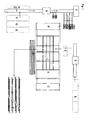
- FIG. 1 is shown a plant for the production of roof elements according to the invention.
- the plant comprises an assembly tank A, a station B for laying sheet piling and a station C for cutting and milling assigned.
- a station B for laying sheet piling and a station C for cutting and milling assigned.
- a separating machine D for boards, sheet piling, gypsum boards and rods are generally assigned.
- a cutting machine E is intended for polystyrene.
- a plate pack F, a piling board package G and a gypsum board package M are provided, which are fed into the station B by means of the cutting machine D and a sheet pile loader I, a plate loader L and a gypsum board loader M.
- a ribbed packet N and a last packet O are provided to be fed to the bank A.
- pre-cut rafters Q, separator plate packs R and a butted partition plate S are provided while waste wood is collected in P.
- the entire materials are assembled in a known manner on the bench to form the so-called main modules to be cut via the station C for the formation of roof elements or sub-modules from a single main module. These submodules are assembled in T into module stacks.
- the design step selects the procedure in a two-dimensional graphic ( FIG. 1 and 2 );
- the roof shown has an outer surface of "profile” and “rafters”, which lie in the same plane.
- the width of which is an average of 2.40 m, except at the eaves corner, which can be transported leaning on the hypotenuse, and can reach greater latitudes.
- the first analysis to be performed is to find the most appropriate coupling between two modules, and once they have been chosen, the actual procedure begins.
- Step 1 In the figures, in the plan view, the two modules to be coupled between the modules from 1 to 11 are taken out.
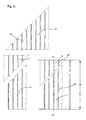
- Step 2 How the FIG. 9 Removable, the distance between the eaves line 12 and the triangle vertex 13 is measured. This measure becomes 14 not the actual length of the module, since it was taken from the top view.
- Step 3 How out FIG. 10 the real length 15 in the development of the roof area is calculated by the dimension 14 being viewed in plan by the cosine of the angle of inclination ⁇ ( FIG. 3 ) of the roof 100 is divided.
- Step 4 The triangle with the real length 15 ( FIG. 10 ) redrawn.
- Step 6 How out FIG. 11 the rafters are extended to the straight line and the designation of the modules is completed.
- Step 7 As shown in Figure 12, one (2) of the two modules (1, 3) is pivoted and it is positioned so that the rafters 17 are aligned with each other.
- Step 8 The distance between the two eaves lines is set by a multiple amount 18 of the plank covering.
- Step 9 Should the pitch of the tile carrier bars be approximately twice the plank lining pitch, which can be coordinated very often, the multiple spacing of the grid spacing will be adjusted. In determining these sizes, a tolerance can be provided by changing the starting point and the arrival point of the plank covering (which may also project from the head of the rafters by 3-4 cm) and use the variable pitch of the covering coats, in the worst case between + - 3 mm for each row of tiles fluctuates. It is important to make these decisions and keep them constant for the production of all roof modules.
- Step 10 On assembly tank A, align all of the rafters 17 aligned as shown in the drawing and control the distance between the eaves lines.
- Step 11 The plank flooring is continuously set up on the dual module
- Step 13 Then again in a continuous manner, the brick carrier strips and the top board are set up
- Step 14 Divide the modules with two bevel cuts according to the dimensions of the drawing. The ability to more or less space the two cuts allows for the recovery of the differences between the actual lengths of the modules and the set lengths, a multiple of the pitch.
- the modules thus produced will have on the inside the proper alignment of the joints of the inner lining or the sheet pile and on the outer surface of those of the tile carrier strips.
- Table 1 Plant for the production of roof elements Board 2 exemplary multi-surface roof Board 3 Section III-III off FIG. 2 Board 4 Determination of the modules in the exemplary roof Board 5 Figure 5,6,7,8 Board 6 Figure 9,10 Board 7 FIG. 11 , 12.13
Landscapes
- Engineering & Computer Science (AREA)
- Architecture (AREA)
- Physics & Mathematics (AREA)
- Electromagnetism (AREA)
- Civil Engineering (AREA)
- Structural Engineering (AREA)
- Roof Covering Using Slabs Or Stiff Sheets (AREA)
Applications Claiming Priority (1)
| Application Number | Priority Date | Filing Date | Title |
|---|---|---|---|
| ITIT20090008 | 2009-08-27 |
Publications (2)
| Publication Number | Publication Date |
|---|---|
| EP2299018A2 true EP2299018A2 (fr) | 2011-03-23 |
| EP2299018A3 EP2299018A3 (fr) | 2012-04-04 |
Family
ID=43003460
Family Applications (1)
| Application Number | Title | Priority Date | Filing Date |
|---|---|---|---|
| EP10174007A Withdrawn EP2299018A3 (fr) | 2009-08-27 | 2010-08-25 | Procédé de fabrication d'éléments de toit préfabriqués et installation destinée à sa réalisation |
Country Status (1)
| Country | Link |
|---|---|
| EP (1) | EP2299018A3 (fr) |
Family Cites Families (5)
| Publication number | Priority date | Publication date | Assignee | Title |
|---|---|---|---|---|
| DE2646533B2 (de) * | 1976-10-15 | 1978-08-10 | Oswald 8542 Roth Lux | Walmdachkonstruktion aus hölzernen, vorgefertigten Dachelementen |
| US5365705A (en) * | 1991-06-07 | 1994-11-22 | Massachusetts Institute Of Technology | Roof panel design and single beam roof assembly |
| DE19743685C1 (de) * | 1997-10-02 | 1999-02-11 | Braas Gmbh | Bausatz zum Herstellen einer selbsttragenden Dachkonstruktion für ein geneigtes Dach |
| US7225596B2 (en) * | 2003-03-31 | 2007-06-05 | Pn Ii, Inc. | Self supportive panel system |
| US7467469B2 (en) * | 2005-09-07 | 2008-12-23 | Harlin Wall | Modular housing system and method of manufacture |
-
2010
- 2010-08-25 EP EP10174007A patent/EP2299018A3/fr not_active Withdrawn
Non-Patent Citations (1)
| Title |
|---|
| None |
Also Published As
| Publication number | Publication date |
|---|---|
| EP2299018A3 (fr) | 2012-04-04 |
Similar Documents
| Publication | Publication Date | Title |
|---|---|---|
| DE2837429A1 (de) | Vorrichtung und verfahren zum aufbau einer fliesenwand | |
| EP0019058B1 (fr) | Procédé pour l'isolation thermique de parties de bâtiments | |
| CN104818792A (zh) | 曲型屋面模板系统测控施工方法 | |
| CA2442076A1 (fr) | Presse a endosser amelioree pour bardeaux composites a languettes | |
| EP0549750A1 (fr) | Modele de panneau de toiture et ensemble de toiture a une seule poutre | |
| DE3785051T2 (de) | Methode zum errichten von trennlinien auf einem stockwerk, welches in kleinere raeume unterteilt wird, und elemente zum ausfuehren dieser methode. | |
| DE3130190A1 (de) | "bodenplatte" | |
| CN1343150A (zh) | 结构元件及其制造 | |
| EP3513932B1 (fr) | Procédé de fabrication d'éléments muraux à partir de matières clouables et / ou serrables | |
| EP2299018A2 (fr) | Procédé de fabrication d'éléments de toit préfabriqués et installation destinée à sa réalisation | |
| AU2024204259A1 (en) | Modular building structures, methods and systems | |
| US3853162A (en) | Method of prefabricating a truss | |
| EP4134215A1 (fr) | Ligne de production d'éléments de construction en bois | |
| AU620817B2 (en) | Improvements in or relating to a jig and a method of forming a panel for a building | |
| DE202019103734U1 (de) | Kehlplatte bzw. Gratplatte | |
| US3073364A (en) | Grading shingle cutter guide device | |
| DE19730184C2 (de) | Stahlbeton-Bauverfahren für ausschließlich dreidimensional bestimmbare Baukörper | |
| DE102023118498A1 (de) | Fassadenmodul, Fassadenmodulsystem und Verfahren zur Herstellung und Montage des Fassadenmoduls | |
| DE19627975A1 (de) | Verfahren zur Herstellung von Schalungselementen für Mantelbetonbauweise | |
| RU2771270C1 (ru) | Линия по производству сборных несущих конструкций | |
| DE3604408A1 (de) | Dachflaechen-begrenzungsstein, insbesondere gratstein | |
| DE3627518C2 (fr) | ||
| DE102023135130A1 (de) | Verfahren zur Herstellung von Gebäudeelementen | |
| DE19622044C2 (de) | Ziegeldach zur Überdeckung einer gekrümmten Dachfläche | |
| DE3602514A1 (de) | Schindelelement und verfahren zum verschindeln |
Legal Events
| Date | Code | Title | Description |
|---|---|---|---|
| PUAI | Public reference made under article 153(3) epc to a published international application that has entered the european phase |
Free format text: ORIGINAL CODE: 0009012 |
|
| AK | Designated contracting states |
Kind code of ref document: A2 Designated state(s): AL AT BE BG CH CY CZ DE DK EE ES FI FR GB GR HR HU IE IS IT LI LT LU LV MC MK MT NL NO PL PT RO SE SI SK SM TR |
|
| AX | Request for extension of the european patent |
Extension state: BA ME RS |
|
| PUAL | Search report despatched |
Free format text: ORIGINAL CODE: 0009013 |
|
| AK | Designated contracting states |
Kind code of ref document: A3 Designated state(s): AL AT BE BG CH CY CZ DE DK EE ES FI FR GB GR HR HU IE IS IT LI LT LU LV MC MK MT NL NO PL PT RO SE SI SK SM TR |
|
| AX | Request for extension of the european patent |
Extension state: BA ME RS |
|
| RIC1 | Information provided on ipc code assigned before grant |
Ipc: E04B 7/22 20060101ALI20120227BHEP Ipc: E04B 7/20 20060101ALI20120227BHEP Ipc: E04B 7/06 20060101AFI20120227BHEP |
|
| STAA | Information on the status of an ep patent application or granted ep patent |
Free format text: STATUS: THE APPLICATION IS DEEMED TO BE WITHDRAWN |
|
| 18D | Application deemed to be withdrawn |
Effective date: 20121005 |