EP2299041A2 - Dispositif d'amortissement pour éléments de meuble mobiles - Google Patents
Dispositif d'amortissement pour éléments de meuble mobiles Download PDFInfo
- Publication number
- EP2299041A2 EP2299041A2 EP10176609A EP10176609A EP2299041A2 EP 2299041 A2 EP2299041 A2 EP 2299041A2 EP 10176609 A EP10176609 A EP 10176609A EP 10176609 A EP10176609 A EP 10176609A EP 2299041 A2 EP2299041 A2 EP 2299041A2
- Authority
- EP
- European Patent Office
- Prior art keywords
- cylinder
- housing
- damper device
- recess
- stop
- Prior art date
- Legal status (The legal status is an assumption and is not a legal conclusion. Google has not performed a legal analysis and makes no representation as to the accuracy of the status listed.)
- Withdrawn
Links
- 238000006073 displacement reaction Methods 0.000 claims abstract description 24
- 230000015572 biosynthetic process Effects 0.000 claims description 21
- 238000000465 moulding Methods 0.000 abstract description 4
- 239000002184 metal Substances 0.000 abstract description 2
- 238000013016 damping Methods 0.000 description 8
- 238000003780 insertion Methods 0.000 description 8
- 230000037431 insertion Effects 0.000 description 8
- 230000000694 effects Effects 0.000 description 5
- 238000004519 manufacturing process Methods 0.000 description 4
- 230000006978 adaptation Effects 0.000 description 1
- 239000011324 bead Substances 0.000 description 1
- 239000002131 composite material Substances 0.000 description 1
- 239000000463 material Substances 0.000 description 1
- 230000000717 retained effect Effects 0.000 description 1
Images


Classifications
-
- E—FIXED CONSTRUCTIONS
- E05—LOCKS; KEYS; WINDOW OR DOOR FITTINGS; SAFES
- E05F—DEVICES FOR MOVING WINGS INTO OPEN OR CLOSED POSITION; CHECKS FOR WINGS; WING FITTINGS NOT OTHERWISE PROVIDED FOR, CONCERNED WITH THE FUNCTIONING OF THE WING
- E05F5/00—Braking devices, e.g. checks; Stops; Buffers
- E05F5/02—Braking devices, e.g. checks; Stops; Buffers specially for preventing the slamming of swinging wings during final closing movement, e.g. jamb stops
-
- E—FIXED CONSTRUCTIONS
- E05—LOCKS; KEYS; WINDOW OR DOOR FITTINGS; SAFES
- E05F—DEVICES FOR MOVING WINGS INTO OPEN OR CLOSED POSITION; CHECKS FOR WINGS; WING FITTINGS NOT OTHERWISE PROVIDED FOR, CONCERNED WITH THE FUNCTIONING OF THE WING
- E05F5/00—Braking devices, e.g. checks; Stops; Buffers
- E05F5/003—Braking devices, e.g. checks; Stops; Buffers for sliding wings
-
- E—FIXED CONSTRUCTIONS
- E05—LOCKS; KEYS; WINDOW OR DOOR FITTINGS; SAFES
- E05Y—INDEXING SCHEME ASSOCIATED WITH SUBCLASSES E05D AND E05F, RELATING TO CONSTRUCTION ELEMENTS, ELECTRIC CONTROL, POWER SUPPLY, POWER SIGNAL OR TRANSMISSION, USER INTERFACES, MOUNTING OR COUPLING, DETAILS, ACCESSORIES, AUXILIARY OPERATIONS NOT OTHERWISE PROVIDED FOR, APPLICATION THEREOF
- E05Y2201/00—Constructional elements; Accessories therefor
- E05Y2201/20—Brakes; Disengaging means; Holders; Stops; Valves; Accessories therefor
- E05Y2201/21—Brakes
- E05Y2201/212—Buffers
-
- E—FIXED CONSTRUCTIONS
- E05—LOCKS; KEYS; WINDOW OR DOOR FITTINGS; SAFES
- E05Y—INDEXING SCHEME ASSOCIATED WITH SUBCLASSES E05D AND E05F, RELATING TO CONSTRUCTION ELEMENTS, ELECTRIC CONTROL, POWER SUPPLY, POWER SIGNAL OR TRANSMISSION, USER INTERFACES, MOUNTING OR COUPLING, DETAILS, ACCESSORIES, AUXILIARY OPERATIONS NOT OTHERWISE PROVIDED FOR, APPLICATION THEREOF
- E05Y2201/00—Constructional elements; Accessories therefor
- E05Y2201/60—Suspension or transmission members; Accessories therefor
- E05Y2201/622—Suspension or transmission members elements
- E05Y2201/696—Screw mechanisms
-
- E—FIXED CONSTRUCTIONS
- E05—LOCKS; KEYS; WINDOW OR DOOR FITTINGS; SAFES
- E05Y—INDEXING SCHEME ASSOCIATED WITH SUBCLASSES E05D AND E05F, RELATING TO CONSTRUCTION ELEMENTS, ELECTRIC CONTROL, POWER SUPPLY, POWER SIGNAL OR TRANSMISSION, USER INTERFACES, MOUNTING OR COUPLING, DETAILS, ACCESSORIES, AUXILIARY OPERATIONS NOT OTHERWISE PROVIDED FOR, APPLICATION THEREOF
- E05Y2600/00—Mounting or coupling arrangements for elements provided for in this subclass
- E05Y2600/10—Adjustable
- E05Y2600/12—Adjustable by manual operation
-
- E—FIXED CONSTRUCTIONS
- E05—LOCKS; KEYS; WINDOW OR DOOR FITTINGS; SAFES
- E05Y—INDEXING SCHEME ASSOCIATED WITH SUBCLASSES E05D AND E05F, RELATING TO CONSTRUCTION ELEMENTS, ELECTRIC CONTROL, POWER SUPPLY, POWER SIGNAL OR TRANSMISSION, USER INTERFACES, MOUNTING OR COUPLING, DETAILS, ACCESSORIES, AUXILIARY OPERATIONS NOT OTHERWISE PROVIDED FOR, APPLICATION THEREOF
- E05Y2600/00—Mounting or coupling arrangements for elements provided for in this subclass
- E05Y2600/10—Adjustable
- E05Y2600/20—Adjustable with specific transmission movement
-
- E—FIXED CONSTRUCTIONS
- E05—LOCKS; KEYS; WINDOW OR DOOR FITTINGS; SAFES
- E05Y—INDEXING SCHEME ASSOCIATED WITH SUBCLASSES E05D AND E05F, RELATING TO CONSTRUCTION ELEMENTS, ELECTRIC CONTROL, POWER SUPPLY, POWER SIGNAL OR TRANSMISSION, USER INTERFACES, MOUNTING OR COUPLING, DETAILS, ACCESSORIES, AUXILIARY OPERATIONS NOT OTHERWISE PROVIDED FOR, APPLICATION THEREOF
- E05Y2600/00—Mounting or coupling arrangements for elements provided for in this subclass
- E05Y2600/10—Adjustable
- E05Y2600/30—Adjustment motion
- E05Y2600/31—Linear motion
- E05Y2600/312—Horizontal motion
-
- E—FIXED CONSTRUCTIONS
- E05—LOCKS; KEYS; WINDOW OR DOOR FITTINGS; SAFES
- E05Y—INDEXING SCHEME ASSOCIATED WITH SUBCLASSES E05D AND E05F, RELATING TO CONSTRUCTION ELEMENTS, ELECTRIC CONTROL, POWER SUPPLY, POWER SIGNAL OR TRANSMISSION, USER INTERFACES, MOUNTING OR COUPLING, DETAILS, ACCESSORIES, AUXILIARY OPERATIONS NOT OTHERWISE PROVIDED FOR, APPLICATION THEREOF
- E05Y2600/00—Mounting or coupling arrangements for elements provided for in this subclass
- E05Y2600/60—Mounting or coupling members; Accessories therefor
- E05Y2600/622—Dowels; Pins
-
- E—FIXED CONSTRUCTIONS
- E05—LOCKS; KEYS; WINDOW OR DOOR FITTINGS; SAFES
- E05Y—INDEXING SCHEME ASSOCIATED WITH SUBCLASSES E05D AND E05F, RELATING TO CONSTRUCTION ELEMENTS, ELECTRIC CONTROL, POWER SUPPLY, POWER SIGNAL OR TRANSMISSION, USER INTERFACES, MOUNTING OR COUPLING, DETAILS, ACCESSORIES, AUXILIARY OPERATIONS NOT OTHERWISE PROVIDED FOR, APPLICATION THEREOF
- E05Y2600/00—Mounting or coupling arrangements for elements provided for in this subclass
- E05Y2600/60—Mounting or coupling members; Accessories therefor
- E05Y2600/63—Retainers
-
- E—FIXED CONSTRUCTIONS
- E05—LOCKS; KEYS; WINDOW OR DOOR FITTINGS; SAFES
- E05Y—INDEXING SCHEME ASSOCIATED WITH SUBCLASSES E05D AND E05F, RELATING TO CONSTRUCTION ELEMENTS, ELECTRIC CONTROL, POWER SUPPLY, POWER SIGNAL OR TRANSMISSION, USER INTERFACES, MOUNTING OR COUPLING, DETAILS, ACCESSORIES, AUXILIARY OPERATIONS NOT OTHERWISE PROVIDED FOR, APPLICATION THEREOF
- E05Y2800/00—Details, accessories and auxiliary operations not otherwise provided for
-
- E—FIXED CONSTRUCTIONS
- E05—LOCKS; KEYS; WINDOW OR DOOR FITTINGS; SAFES
- E05Y—INDEXING SCHEME ASSOCIATED WITH SUBCLASSES E05D AND E05F, RELATING TO CONSTRUCTION ELEMENTS, ELECTRIC CONTROL, POWER SUPPLY, POWER SIGNAL OR TRANSMISSION, USER INTERFACES, MOUNTING OR COUPLING, DETAILS, ACCESSORIES, AUXILIARY OPERATIONS NOT OTHERWISE PROVIDED FOR, APPLICATION THEREOF
- E05Y2900/00—Application of doors, windows, wings or fittings thereof
- E05Y2900/20—Application of doors, windows, wings or fittings thereof for furniture, e.g. cabinets
Definitions
- the invention relates to a damper device for movable furniture parts with a housing fixed to a furniture body and with a housing arranged in a recess in which a piston is slidably mounted slidably, which forms a stop for a movable furniture part, wherein the cylinder in the axial Direction in the recess in the housing is displaceable and the housing has adapted to the cross-sectional area of the piston Kolben presslassö réelle with an opening edge which forms a axial displacement of the cylinder defining the front end stop.
- damper devices are known from practice and are used for damping, for example, a closing movement of a furniture door or a drawer element before the furniture door or the drawer element strike at a predetermined by the furniture body stop, so slowing down the closing movements towards the end and an excessively sudden, or hard striking the movable furniture part is prevented.
- the axially displaceable in the recess of the housing cylinder is usually inserted from behind into the recess and fixed in the intended position, so that the piston protrudes through the piston passage opening on the housing.
- An axial displacement of the cylinder can be effected, for example, by rotating the piston accessible from the front or the cylinder accessible from a rear side of the housing.
- damper devices known in practice, in which the axial displacement of the cylinder can be effected for example by an adjusting screw or a gear.
- the housing has a front on a front side facing the movable furniture part End stop, which prevents removal of the cylinder together with the piston slidably mounted therein. Due to the design of the cylinder can be inserted from a rear side of the housing in the recess provided and also removed again.
- damper devices are not considered to be child resistant, as the cylinder could be removed from the housing substantially unhindered at the back of the housing and, for example, swallowed by a child.
- the cylinder has a radially projecting portion and that at a front end stop facing away from the end of the recess, a stop element is arranged, which limits its axial displacement by a positive engagement with the radially projecting portion of the cylinder.
- the stop member which forms an abutment for a side surface of the radially projecting portion of the cylinder upon axial displacement of the cylinder and prevents its axial displacement beyond the stop member, can already be provided and formed without a significant overhead during manufacture or be retrofitted.
- the front end stop and arranged at the rear of the housing stop member provide an adjustment range, within which the radially projecting portion of the cylinder can be freely displaced in the axial direction.
- the axial displacement of the cylinder required for an adjustment of the damper device or the adaptation of the damping effect to the movable furniture part to be damped is not impeded or hindered within the adjustment range.
- the stop element prevents with simple, but effective structural means removal of the cylinder from the recess provided for the cylinder in the housing.
- the radially projecting portion of the cylinder has an external thread.
- the recess in the housing may have a threaded portion adapted thereto, so that the cylinder is in threaded engagement over the entire extent of the radially projecting portion with the recess.
- the radially projecting portion should expediently have a sufficient axial extent to accommodate at least several complete revolutions of the thread can, so that a reliable storage and displacement of the cylinder can be ensured in the recess.
- a removal of the cylinder from the housing of the damper device can be reliably prevented in that the stop element is a radially inwardly projecting formation in the cylinder receiving recess.
- the radially inwardly projecting Forming may be formed bead-shaped along a circumferential line on an inner side of the recess.
- the stopper member may also include a plurality of spaced apart along a circumferential line formed inwardly projecting stop cam or the like.
- a large adjustment range of the cylinder within the housing can be made possible in that the radially inwardly projecting formation is formed by an opening edge surrounding a cylinder passage opening.
- the stop element can correspond in functional and in terms of design to the front end stop.
- a housing with a stop element delimiting the axial displacement of the cylinder accommodated in the recess can be produced in a simple manner by configuring the housing in two parts at least in a region around the radially inwardly projecting formation.
- the cylinder can be inserted in such an embodiment of the housing in the recess or inserted therein before the two housing parts are connected to each other and set the cylinder in the adjustment of the housing.
- a two-part embodiment of the housing also has the advantage that the housing can have one or more cavities and can be produced to save material.
- the two housing parts which form, for example, two substantially symmetrically configured housing halves
- both an attachment of the two housing halves to the furniture body as well as a Merging and connection of the two housing halves is effected, which surround the cylinder in the recess.
- the two housing halves can be joined together either during assembly of the damper device to the furniture body or assembled by means of a separate fastening device following the production of the individual components and offered as a prefabricated damper device and sold.
- the stop element is a radially inwardly projecting formation in a sleeve-shaped attachment portion which projects at an end remote from the front end stop of the recess in the axial direction.
- a reliable, mechanically extremely strong limitation of the axial displacement of the cylinder can be effected in that the sleeve-shaped mounting portion consists of metal and the radially inwardly projecting formation is produced by cold deformation.
- the housing of the damper device can be produced together with the sleeve-shaped designed attachment portion.
- the cylinder can be inserted through the sleeve-shaped attachment portion into the recess of the housing and positioned therein before forming in a subsequent step by cold deformation of a rear end portion of the sleeve-shaped mounting portion a the axial displacement of the cylinder limiting stop member or a radially inwardly projecting formation ,
- the sleeve-shaped attachment portion consists of plastic and the radially inwardly projecting molding is produced by plastic deformation.
- the housing may be formed substantially in one piece. An assembly of several housing parts is therefore eliminated during the manufacture or assembly of the damper device.
- the stop element is a locking element which can be fixed transversely to the axial direction of the cylinder.
- An attachable to the housing locking element can optionally also be retrofitted.
- the locking element can be removed from a locking position on or in the housing to allow the insertion or subsequent removal of the cylinder from the recess.
- the locking element In order to fix the cylinder in the recess of the housing and to limit its axial displacement, the locking element must optionally be fixed again on or in the housing.
- the locking element is arranged laterally next to the cylinder.
- the locking element forms a stop arranged laterally next to the cylinder for the radially projecting portion of the cylinder.
- the Locking element is a fastening element for fixing the housing to the furniture body.
- the locking element can be, for example, a fastening screw, which has a threadless section in a region assigned to the cylinder, which can form a stop for the radially projecting section of the cylinder.
- the fastening screw is passed through a suitably arranged bore of the housing and screwed into the furniture body. Simultaneously with the screwing of the housing to the furniture body, the axial displacement of the cylinder limiting stop element is set in the housing.
- the stop element is a locking plate surrounding the cylinder with a recess.
- the recess of the locking plate is suitably adapted to the dimensions of the radially projecting portion of the cylinder and allows in a first, open position of the locking plate, the insertion or removal of the cylinder from the recess in the housing.
- the locking plate may conveniently be displaced in a guide formed in the housing from the open position to a locking position in which the locking plate forms a stop for the radially projecting portion of the cylinder and limits its axial displacement.
- the locking plate is deformed after insertion of the cylinder into the recess, for example by external force and forms a stop for the radially projecting portion of the cylinder in a deformed state.
- the locking element or the locking plate can be releasably connected to the housing and allow a subsequent removal or replacement of the cylinder with the damping piston mounted therein.
- the stop element is pivotally mounted laterally next to the cylinder.
- the stop member may be laterally pivoted away from the cylinder and allow unimpeded insertion of the cylinder from behind into the recess up to the front end stop of the housing. Thereafter, the stopper member can be pivoted laterally to the cylinder until the stopper member fits tightly against an outer wall of the cylinder. In this locking position expediently forms a front end stop facing the end face of the stop member a stop for the radially projecting portion of the cylinder and thereby limits the usable for an axial displacement adjustment of the cylinder.
- the stop element is designed tongue-shaped and connected at its end remote from the front end stop of the housing via a tapering region with the housing surrounding the recess.
- the stop element radially projecting beyond the housing to the outside Has molding that faces the furniture body and causes a pivoting of the stop member in a locking position when attaching the housing to the furniture body. In this way it is ensured that the stop element is pivoted into its locking position, as long as the housing is attached to the furniture body.
- the cylinder is suitably inserted in the recess before the attachment of the housing to the furniture body, so that the assembly of the cylinder is not hindered by the pivoted stop member or made completely impossible.
- the stop element is preferably manufactured in one piece with the housing, so that no separate component has to be produced and kept ready for assembly.
- a pivotally mounted tongue-shaped stop element in a simple manner in one piece, or formed in a plastic housing and be connected via a film hinge or the like with a housing portion surrounding the cylinder.
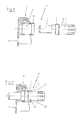
- a housing 2 of the damper device 1 has a housing 2 of the damper device 1, two substantially mirror-symmetrical housing halves 3, of which in the Fig. 1 and 2 only one housing half 3 is shown in each case.
- the housing 2 has a recess 4 extending transversely through the housing 2, in which a cylinder 5 with a piston 6 displaceably mounted in a damped manner is provided.
- a rounded end surface 7 of the piston 6 forms a stop surface for a movable furniture part, which is not shown in the figures.
- the damper device 1 is arranged and attached to a likewise not shown furniture body, that for example against the end of a closing movement, the furniture part abuts the end face 7 of the piston 6 and the piston 6 slows down the closing movement, so that an excessively sudden or hard striking the movable Furniture part is prevented to the furniture body.
- the cylinder 5 has a radially projecting portion 8 with an external thread 9.
- the recess 4 has an internal thread 10 adapted thereto, so that the cylinder 5 is in threaded engagement with the recess 4 in the region of the radially projecting section 8 and can be displaced in the axial direction in the recess 4 by rotation of the cylinder 5.
- To a twisting of the cylinder 5 To facilitate, the cylinder 5 on a piston 6 facing away from the end 11 projecting grip beads 12.
- the cylinder 5 annularly surrounded formation 19 is arranged, which constitutes a stop element for the radially projecting portion 8 of the cylinder 5.
- the inwardly projecting formation 19 engages behind the radially projecting portion 8 of the cylinder 5 and forms on a rear side 20 of the housing 2 a axial displacement of the cylinder 5 in the recess 4 limiting rear end stop.
- the radially projecting portion 8 of the cylinder 5 can be displaced in an axial direction by turning the cylinder 5 in an adjusting region located between the front end stop 16 and the rear, radially inwardly projecting formation 19, one over the housing 2 and the housing 2 surrounding area of one Furniture carcass protruding portion 21 of the piston 6 to be able to adapt to the intended damping effect.
- the housing 2 consists of two housing halves 3, which are manufactured separately and joined together before or during an attachment of the housing 2 to the furniture body, the housing 2 or each housing half 3 can have, in addition to the recess 4, further recesses or cavities 22, so that a material-saving production of a damper device with a low weight is possible.
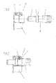
- One in the 4 and 5 Imaged damper device 23 has a one-piece manufactured housing 2.
- a sleeve-shaped mounting portion 24 whose inner diameter is first ( Fig. 4 ) is greater than the outer diameter of the projecting portion 8 of the cylinder 5, so that the cylinder 5 can be inserted from the back 20 of the housing 2 in the recess 4 and stored therein.
- a radially inwardly projecting formation 25 is produced on the sleeve-shaped fastening portion 24 by cold deformation.
- the radially inwardly projecting formation 25 forms a rear end stop 26 for the projecting portion 8 of the cylinder 5 in the recess 4 and limits its axial displacement path to a region between the front end stop 16 formed by the opening edge 15 and the rear end stop 26, which is formed by the radially inwardly projecting formation 25.
- One in the 6 and 7 mapped damper device 27 has a locking pin 28 which can be fixed in a bore 29 in the housing 2 laterally adjacent to the cylinder 5.
- the cylinder 5 has a locking portion 30 with a small, adapted to the radial distance of the locking pin 28 diameter, which allows an axial displacement of the cylinder 5 relative to the locking pin 28.
- the cylinder 5 can be freely inserted or removed in the recess 4 with the locking pin 28 removed, while the cylinder 5 is reliably retained in the recess 4 by the locking pin 28 defined in the bore 29.
- damper device 31 At one in the 8 to 11 damper device 31 shown is a cylinder 5 in the recess 4 retaining locking plate 32 transverse to the axial extent of the cylinder 5, and the recess 4 arranged in a guide 33 in the housing and stored.
- the locking plate 32 has an approximately oval recess 34 adapted to the dimensions of the cylinder 5.
- the locking plate 32 can be inserted into the recess 33 in the guide 33 before insertion of the cylinder 5 and stored in an open position, in which the oval recess 34, the recess 4 releases ( Fig. 9 ). After insertion of the cylinder 5 in the recess 4, the locking plate 32 is laterally displaced into a locking position ( Fig.
- the arrangement of the locking plate 32 in the guide 33 in the housing 2 may be configured such that upon attachment of the damper device 31 to a furniture body 36, the locking plate 32 is locked in a locking position.
- the cylinder 5 located in the recess 4 in the housing 2 can only be removed from the housing 2, or from the recess 4, after the damper device 31 has been detached from the furniture body 36 and a subsequent displacement of the locking plate 32 in the guide 33.
- the housing 2 forms a substantially surrounding the cylinder 5, sleeve-shaped guide and limited to the storage of the cylinder 5 provided recess 4.
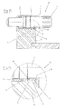
- a tongue-shaped stop member 38 is arranged in a furniture body 36 facing region.
- the tongue-shaped stop element 38 is connected at a front end stop 16 of the housing 2 facing away from the end 39 of the stop member 38 via a tapered portion 40 with the cylinder 5 surrounding the housing 2 and can be due to the deformation properties of the tapered portion 40 at least a little on the cylinder. 5 Swing to or from the cylinder 5 away.
- the stop element 38 has on a side facing away from the cylinder 5 a radially outwardly projecting formation 41, which faces the furniture body 36.
- the damper device 37 is shown spaced from the furniture body 36, so that the stop element 38 is pivoted outwardly and allows unimpeded insertion of the cylinder 5 into the recess 4 into it.
- the molding 41 can protrude radially beyond the housing 2, or protrude laterally.
- the damper device is shown in a position attached to the furniture body 36 position.
- the radially projecting formation 41 of the tongue-shaped stop member 38 With the surface 42 in contact and causes up to a complete approach of the housing 2 to the furniture body 36 pivoting
- the tongue-shaped stop member 38 is fixed in the pivoted to the cylinder 5 out position, or in a locking position of the tongue-shaped stop member 38 to the cylinder 5 and away from the surface 42 of the furniture body.
- a front end stop 16 facing end face 43 of the tongue-shaped stop member 38 forms a stop for the radially projecting portion 8 of the cylinder 5 and limited in this way reliably its axial adjustment in the recess 4.
- a removal of the cylinder 5 via the rear end portion 18 of the casing 2 is reliably prevented by the positive engagement of the tongue-shaped stop member 38 with the radially projecting portion 8 of the cylinder 5.
- the cylinder 5 can be destructively remove only from the recess 4 of the housing 2, when the housing 2 of the damper device again detached from the furniture body 36 and the pivotable stop member 38 released again and is given away by the Cylidner 5 away.
Landscapes
- Fluid-Damping Devices (AREA)
Applications Claiming Priority (2)
| Application Number | Priority Date | Filing Date | Title |
|---|---|---|---|
| DE102009044018A DE102009044018A1 (de) | 2009-09-16 | 2009-09-16 | Dämpfereinrichtung für bewegbare Möbelteile |
| DE202009013715U DE202009013715U1 (de) | 2009-09-16 | 2009-11-11 | Dämpfereinrichtung für bewegbare Möbelteile |
Publications (2)
| Publication Number | Publication Date |
|---|---|
| EP2299041A2 true EP2299041A2 (fr) | 2011-03-23 |
| EP2299041A3 EP2299041A3 (fr) | 2013-08-21 |
Family
ID=42169097
Family Applications (1)
| Application Number | Title | Priority Date | Filing Date |
|---|---|---|---|
| EP10176609.5A Withdrawn EP2299041A3 (fr) | 2009-09-16 | 2010-09-14 | Dispositif d'amortissement pour éléments de meuble mobiles |
Country Status (2)
| Country | Link |
|---|---|
| EP (1) | EP2299041A3 (fr) |
| DE (2) | DE102009044018A1 (fr) |
Cited By (5)
| Publication number | Priority date | Publication date | Assignee | Title |
|---|---|---|---|---|
| EP2511463A1 (fr) | 2011-04-15 | 2012-10-17 | Roto Frank Ag | Fenêtre, porte ou analogue pourvue d'un dispositif d'amortissement |
| JP2015515564A (ja) * | 2012-04-25 | 2015-05-28 | ヘティッヒ−オーエヌイー ゲーエムベーハー ウント ツェーオー.カーゲー | スライドドア取付具 |
| DE102016002110A1 (de) | 2016-02-15 | 2017-08-17 | Siegenia-Aubi Kg | Dämpfungseinrichtung für einen parallel verschiebbaren Flügel als Schiebekippflügel oder Schiebeflügel |
| US10111524B2 (en) | 2013-01-30 | 2018-10-30 | Julius Blum Gmbh | Furniture fitting |
| CN111852232A (zh) * | 2020-07-03 | 2020-10-30 | 广东精诺五金实业有限公司 | 一种阻尼器及阻尼铰链 |
Family Cites Families (5)
| Publication number | Priority date | Publication date | Assignee | Title |
|---|---|---|---|---|
| JPS556315U (fr) * | 1978-06-27 | 1980-01-16 | ||
| DE3729597A1 (de) * | 1987-09-04 | 1989-03-16 | Karl Liedgens | Tuerschliessdaempfer |
| DE20200798U1 (de) * | 2001-06-08 | 2002-04-04 | Julius Blum Ges.m.b.H., Höchst | Dämpfeinrichtung für bewegbare Möbelteile |
| NL1025252C2 (nl) * | 2004-01-15 | 2004-09-21 | Gjdw Gmbh | Schok- en rammeldemper. |
| US7032271B2 (en) * | 2004-04-02 | 2006-04-25 | Jung-Hui Lin | Noise control device for a steel door |
-
2009
- 2009-09-16 DE DE102009044018A patent/DE102009044018A1/de not_active Withdrawn
- 2009-11-11 DE DE202009013715U patent/DE202009013715U1/de not_active Expired - Lifetime
-
2010
- 2010-09-14 EP EP10176609.5A patent/EP2299041A3/fr not_active Withdrawn
Non-Patent Citations (1)
| Title |
|---|
| None |
Cited By (6)
| Publication number | Priority date | Publication date | Assignee | Title |
|---|---|---|---|---|
| EP2511463A1 (fr) | 2011-04-15 | 2012-10-17 | Roto Frank Ag | Fenêtre, porte ou analogue pourvue d'un dispositif d'amortissement |
| JP2015515564A (ja) * | 2012-04-25 | 2015-05-28 | ヘティッヒ−オーエヌイー ゲーエムベーハー ウント ツェーオー.カーゲー | スライドドア取付具 |
| US10111524B2 (en) | 2013-01-30 | 2018-10-30 | Julius Blum Gmbh | Furniture fitting |
| DE102016002110A1 (de) | 2016-02-15 | 2017-08-17 | Siegenia-Aubi Kg | Dämpfungseinrichtung für einen parallel verschiebbaren Flügel als Schiebekippflügel oder Schiebeflügel |
| CN111852232A (zh) * | 2020-07-03 | 2020-10-30 | 广东精诺五金实业有限公司 | 一种阻尼器及阻尼铰链 |
| CN111852232B (zh) * | 2020-07-03 | 2025-08-12 | 广东精诺五金实业有限公司 | 一种阻尼器及阻尼铰链 |
Also Published As
| Publication number | Publication date |
|---|---|
| DE102009044018A1 (de) | 2011-03-24 |
| DE202009013715U1 (de) | 2010-05-12 |
| EP2299041A3 (fr) | 2013-08-21 |
Similar Documents
| Publication | Publication Date | Title |
|---|---|---|
| EP2286048B1 (fr) | Dispositif amortisseur pour portes de meubles | |
| EP2951373B1 (fr) | Ferrure de meuble | |
| DE102010062565B4 (de) | Winkelverstellbarer Handgriff für ein Handwerkzeug | |
| DE10062277A1 (de) | Türfeststeller | |
| EP2299041A2 (fr) | Dispositif d'amortissement pour éléments de meuble mobiles | |
| EP1304440A2 (fr) | Dispositif de freinage | |
| DE1450990A1 (de) | Befestigungsvorrichtung mit einer von einem Kunststoffhalter umgebenen Gewindemutter | |
| EP2088263B1 (fr) | Serrure cylindrique à retour automatique du panneton | |
| DE10147229B4 (de) | Zugfeder für Klappe an einem Kraftfahrzeug | |
| DE212011100150U1 (de) | Möbeldämpfer | |
| DE20120271U1 (de) | Türfeststeller | |
| DE29610293U1 (de) | Karabinerhaken | |
| EP3392418B1 (fr) | Système de fixation | |
| EP1297265B1 (fr) | Dispositif pour fixer un premier element en position d'espacement par rapport a un deuxieme element | |
| AT515090B1 (de) | Sicherungsvorrichtung für Fenster oder Türen | |
| EP0777025B1 (fr) | Charnière pour porte de véhicule avec fonction de retenue et de freinage | |
| DE102010036172A1 (de) | Kolben mit Sensorelement und Anbindung für eine Kolbenstange | |
| DE102007047287A1 (de) | Möbelscharnier mit einer Dämpfungsvorrichtung | |
| AT523901B1 (de) | Selbstsichernder Vorspannring für Federbeine | |
| DE102012219549A1 (de) | Arretiervorrichtung zum Arretieren einer bewegbaren Komponente | |
| DE102016222831A1 (de) | Scharnier mit einer in einer vorbestimmten Winkelstellung lösbaren Scharnierkomponente | |
| DE102014103580B3 (de) | Hydraulischer Dämpfer mit einem Gehäuse, insbesondere für einen Türschließer | |
| EP3722546A1 (fr) | Charnière pour un appareil, en particulier pour un appareil de cuisine et / ou électroménager ainsi qu'appareil, en particulier appareil de cuisine et / ou électroménager | |
| DE10062276A1 (de) | Türfeststeller | |
| DE102009019108A1 (de) | Dämpfungseinrichtung für Möbeltüren |
Legal Events
| Date | Code | Title | Description |
|---|---|---|---|
| PUAI | Public reference made under article 153(3) epc to a published international application that has entered the european phase |
Free format text: ORIGINAL CODE: 0009012 |
|
| AK | Designated contracting states |
Kind code of ref document: A2 Designated state(s): AL AT BE BG CH CY CZ DE DK EE ES FI FR GB GR HR HU IE IS IT LI LT LU LV MC MK MT NL NO PL PT RO SE SI SK SM TR |
|
| AX | Request for extension of the european patent |
Extension state: BA ME RS |
|
| PUAL | Search report despatched |
Free format text: ORIGINAL CODE: 0009013 |
|
| AK | Designated contracting states |
Kind code of ref document: A3 Designated state(s): AL AT BE BG CH CY CZ DE DK EE ES FI FR GB GR HR HU IE IS IT LI LT LU LV MC MK MT NL NO PL PT RO SE SI SK SM TR |
|
| AX | Request for extension of the european patent |
Extension state: BA ME RS |
|
| RIC1 | Information provided on ipc code assigned before grant |
Ipc: E05F 5/00 20060101AFI20130712BHEP Ipc: E05F 5/02 20060101ALI20130712BHEP |
|
| 17P | Request for examination filed |
Effective date: 20140221 |
|
| RBV | Designated contracting states (corrected) |
Designated state(s): AL AT BE BG CH CY CZ DE DK EE ES FI FR GB GR HR HU IE IS IT LI LT LU LV MC MK MT NL NO PL PT RO SE SI SK SM TR |
|
| STAA | Information on the status of an ep patent application or granted ep patent |
Free format text: STATUS: THE APPLICATION IS DEEMED TO BE WITHDRAWN |
|
| 18D | Application deemed to be withdrawn |
Effective date: 20160401 |