EP2088263B1 - Serrure cylindrique à retour automatique du panneton - Google Patents
Serrure cylindrique à retour automatique du panneton Download PDFInfo
- Publication number
- EP2088263B1 EP2088263B1 EP09150499A EP09150499A EP2088263B1 EP 2088263 B1 EP2088263 B1 EP 2088263B1 EP 09150499 A EP09150499 A EP 09150499A EP 09150499 A EP09150499 A EP 09150499A EP 2088263 B1 EP2088263 B1 EP 2088263B1
- Authority
- EP
- European Patent Office
- Prior art keywords
- spring
- lock cylinder
- cylinder
- cylinder according
- lock
- Prior art date
- Legal status (The legal status is an assumption and is not a legal conclusion. Google has not performed a legal analysis and makes no representation as to the accuracy of the status listed.)
- Active
Links
Images




Classifications
-
- E—FIXED CONSTRUCTIONS
- E05—LOCKS; KEYS; WINDOW OR DOOR FITTINGS; SAFES
- E05B—LOCKS; ACCESSORIES THEREFOR; HANDCUFFS
- E05B17/00—Accessories in connection with locks
- E05B17/04—Devices for coupling the turning cylinder of a single or a double cylinder lock with the bolt operating member
-
- E—FIXED CONSTRUCTIONS
- E05—LOCKS; KEYS; WINDOW OR DOOR FITTINGS; SAFES
- E05B—LOCKS; ACCESSORIES THEREFOR; HANDCUFFS
- E05B15/00—Other details of locks; Parts for engagement by bolts of fastening devices
- E05B15/04—Spring arrangements in locks
-
- E—FIXED CONSTRUCTIONS
- E05—LOCKS; KEYS; WINDOW OR DOOR FITTINGS; SAFES
- E05B—LOCKS; ACCESSORIES THEREFOR; HANDCUFFS
- E05B9/00—Lock casings or latch-mechanism casings ; Fastening locks or fasteners or parts thereof to the wing
- E05B9/04—Casings of cylinder locks
- E05B9/041—Double cylinder locks
-
- E—FIXED CONSTRUCTIONS
- E05—LOCKS; KEYS; WINDOW OR DOOR FITTINGS; SAFES
- E05B—LOCKS; ACCESSORIES THEREFOR; HANDCUFFS
- E05B9/00—Lock casings or latch-mechanism casings ; Fastening locks or fasteners or parts thereof to the wing
- E05B9/04—Casings of cylinder locks
- E05B2009/047—Means for returning cylinder locks to their neutral position
-
- E—FIXED CONSTRUCTIONS
- E05—LOCKS; KEYS; WINDOW OR DOOR FITTINGS; SAFES
- E05B—LOCKS; ACCESSORIES THEREFOR; HANDCUFFS
- E05B15/00—Other details of locks; Parts for engagement by bolts of fastening devices
- E05B15/04—Spring arrangements in locks
- E05B2015/0448—Units of springs; Two or more springs working together
-
- E—FIXED CONSTRUCTIONS
- E05—LOCKS; KEYS; WINDOW OR DOOR FITTINGS; SAFES
- E05B—LOCKS; ACCESSORIES THEREFOR; HANDCUFFS
- E05B15/00—Other details of locks; Parts for engagement by bolts of fastening devices
- E05B15/04—Spring arrangements in locks
- E05B2015/0493—Overcenter springs
Definitions
- the invention relates first to a lock cylinder having a bearing portion and a flange portion having housing, a rotatably mounted in the bearing portion cylinder core, which is rotatably connected to a closing member, and with a return spring which is attached on the one hand to the housing and on the other hand at an eccentric to the axis of rotation of the Cylinder core arranged eccentric engages to turn back the twisted from a neutral position cylinder core back to the neutral position.
- Such a lock cylinder is for example from the DE 10 2006 020 614 A1 previously known.
- a helical compression spring which cooperates with a slider which rides on the cylinder core, but is rotatably coupled to the housing.
- the slider has a control cam which cooperates with a control projection of the closure member such that rotation of the cylinder core from a neutral position results in a return torque which is capable of rotating the rotated lock cylinder back to the neutral position.
- a similar lock cylinder describes the DE 10 2004 048 231 A1 , Again, the return spring of the provision of the twisted cylinder core is used in a neutral position in which the closing member is located substantially in an alignment with the flange portion of the housing.
- a lock cylinder in which a compression spring acts on an eccentric sleeve to apply a return torque to the cylinder core when it is rotated from the neutral position.
- This return spring engages the cylinder core so that it assumes a dead center position in an approximately 180 ° twisted position to the neutral position.
- the DE 102 43 615 A1 describes an electronic cylinder system for panic locks.
- the electronic cylinder system described there has an external rotary knob with axis, which is guided through a cylinder adapter with closing element to the inside of the door.
- This disc carries an eccentric pin on which a tension spring acts.
- the other side of the tension spring is anchored against a door-mounted mounting plate. The tension spring ensures that the closing element is turned back after being twisted.
- Panic locks make the request to the lock cylinder that the closing member of the lock cylinder must always be in a lower neutral position, since otherwise it could hinder the panic function of the lock.
- the invention has for its object to improve a lock cylinder of the type discussed above closing technology.
- each claim represents an independent solution to the problem and can be combined with any other claim.
- the return spring is a compression or tension spring. This is different than the DE 102 43 615 A1 not in a separate, to be fastened on the inside of the door housing, but in a chamber of the flange portion.
- the other hook end of the return spring engages around the eccentric pin of the cylinder core.
- the helical gears of the tension spring are substantially completely in the chamber, which is formed by a housing element.
- the eccentric pin may be the connecting web of two sections of the cylinder core.
- bearing sleeves are made of plastic or metal and are preferably slotted. Due to an axial slot, the bearing sleeve can be clipped onto the eccentric pin or the fastening pin. In the area of the slot edges, the bearing sleeves have radial webs. Before one of the two radial webs is the free end of the hook portion of the spring. Before the other radial web is a portion of the last spring coil, so that the bearing sleeve is connected to the hook ends substantially rotationally fixed. A rotation thus takes place only between bearing sleeve and eccentric pin or mounting pin.
- the concomitant friction is gentle on the material, since the surface pressure is minimized due to the large surfaces sliding against each other.
- the hook ends of the springs remain substantially stationary with respect to the respective bearing sleeve.
- the bearing sleeve also carries on its outer circumferential surface a plurality of axially extending ribs, which have in their center a recess in which the hooked end of the spring rests, so that the hooked end is also centered with respect to the axial direction.
- the chamber in which the spring rests in the neutral position is formed by a housing element which is closed by a further housing element.
- the mounting pin can from a Fixing screw may be formed, with which the two housing elements are screwed to the flange portion of the central housing.
- the return spring engages the cylinder core in such a way that it assumes a dead center position in an approximately 180 ° twisted position to the neutral position, and furthermore a supplementary spring is proposed which only comes into effect in the region of the dead center position. It forces close to the dead center on the cylinder core to a complementary torque, which acts away from the dead center.
- the spring forces of the restoring spring and the supplementary spring add up in the region near the dead center position such that around the dead center position the overall spring characteristic runs steeper and only has a peak in the dead center position.
- the supplementary spring may be a bow spring which consists of a bent wire, wherein the wire is preferably bent into a ring.
- the ring may have the shape of an onion.
- the tip of the annular spring, which adjoin obliquely extending straight stirrup sections, can cooperate with a stop which is mounted in diametrical opposite position to the eccentric pin on the cylinder core.
- the spring tip of the opposite attachment portion of the supplementary spring may be attached to a wall of the chamber, which is located in the flange portion of the housing.
- a spring holder in which the attachment end is tied up with movement play.
- a fastening screw can engage in the ring clearance of the bow spring.
- the eccentric stop carries a role.
- the tip of the supplementary spring interacts with the outer shell wall of this role. Since the Roller can rotate around the stop pin, the dead center position has taken its stability.
- the return spring is not formed by a tension spring, but by a compression spring.
- the two facing away from each other ends of the compression spring in this variant also engage an eccentric pin or on a mounting pin.
- the compression spring In the neutral position, the compression spring is relaxed or slightly biased.
- the eccentric pin In this position in its farthest position to the mounting pin. If the cylinder core is rotated by 180 ° into a position in which the eccentric pin is closest to the fastening pin, the helical spring is almost completely in the chamber.
- the helical turns of the spring in the neutral position are completely in the chamber, are in the compression spring variant, the helical turns of the spring in the neutral position to the maximum rotational position completely in the chamber.
- the compression spring is supported with their ends from each coupling elements.
- the coupling elements can be formed by eyes or bearing shells.
- the coupling elements are formed by a piston and a cylinder, wherein the piston is inserted in the cylinder.
- the piston or cylinder has an eye through which one of the pins, preferably the attachment pin protrudes, which is preferably formed by a fastening screw.
- the piston preferably has a cross-shaped cross-section.
- the opening of the cylinder has a corresponding counter-profile.
- the cylinder has a bearing shell which can be clipped onto the eccentric pin.
- the length of the piston or the cylinder is dimensioned so that the piston is guided in each rotational position of the cylinder core in the cylinder.
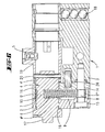
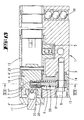
- the lock cylinders shown in the drawings are intended for installation in panic locks.
- Such panic locks have a lock housing with an insertion opening, which corresponds to the cross-sectional profile of the housing 1. This opening has a portion corresponding to the bearing portion 2 and a further portion corresponding to the flange portion 3 of the housing 1.
- Within the housing of the panic lock are a latch and a latch.
- the trap is preconnected by a latch spring and can be withdrawn by pressing a pusher.
- the bolt can be preconnected by means of the lock cylinder. This is done by rotation of the closing member 5. This occurs in a driving recess of the bolt tail. If the internal handle of the panic lock is actuated when the latch is locked, then the door pulls simultaneously with the latch retraction Latch back. This is not blocked by the closing member 5, it must be in the in the FIG. 2 shown neutral position are held.
- the drive of the closing member 5 is carried out with a rotary knob which is fixed to a connecting flange 17 on the cylinder core 4.
- the cylinder core 4 is rotatably connected via a pin 20 with a sleeve 19 of the closing member 5.
- the cylinder core 4 has two sections 4 ', 4 ", which are connected to one another via an eccentric pin 7.
- the cylinder core 4 is rotatably mounted in a bearing bore of the housing elements 14, 15 under the interposition of bushes 16.
- the housing elements 14, 15 are located on the inside of the door On the outside of the door there is likewise a cylinder core and a drill protection 18, which is formed by steel balls which engage in a radial cavity of the flange section 3.
- the housing element 14 forms a chamber 9 which is closed by the housing element 15.
- a fastening screw 8 and a retaining pin 26 hold the housing elements 14, 15 on the central housing 1.
- the fastening screw forms a fastening pin 8, which crosses the chamber 9.
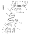
- the shank of the fastening screw is smooth-walled and is partially surrounded by a bearing sleeve 10.
- the bearing sleeve 10 supports a hook end 16 of a helical gear spring 6.
- the other hook end 6 'of the tension spring 6 also engages with the interposition of a bearing sleeve 10 on the eccentric pin 7 on.
- the two bearing sleeves 10 are designed substantially the same and can be made of metal or of a plastic.
- the bearing sleeves 10 have an axial slot, so that they can be clipped onto the fastening pin 8 or the eccentric pin 7.
- the edges of the axial slot form radially projecting webs 11, 12.
- In front of the web 12 lies the free end of the hook 6 'or 6 "
- Sheath outside of the bearing sleeve 10 are located two spaced apart axial ribs 13 with a recess provided in the middle of the rib. In this recess lies the hook end 6 ', 6 ", so that the spring 6 is connected in a rotationally fixed and axially fixed manner to the bearing sleeve 19.
- the inner circumferential surface of the two bearing sleeves 10 slide on the outer walls of the eccentric pin 7 or of the fastening pin 8.
- the eccentric pin 7 has the same radial position as the closing member 5.
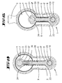
- the spring 6 forms a return spring to the closing member 5 in the in the FIGS. 2 and 3 to keep shown neutral position.
- the neutral position the helical turns of the restoring spring 6 are located substantially in the chamber 9 formed by the flange section 3. Is the cylinder core 4 in the in the FIGS. 4 and 6 rotated position shown, the return spring 6 is tensioned.
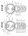
- the return spring 6 In the FIGS. 4 and 6 takes the cylinder core 4 a dead center. He is held there in an unstable equilibrium. If the cylinder core 4 slightly from this dead center, for example in the in FIG. 5 shifted position shown, the return spring 6 generates a torque on the cylinder core 4 and turns the cylinder core 4 automatically in the in the FIGS. 2 and 3 shown neutral position back.
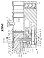
- the supplementary spring 22 is a bow spring made of a spring steel wire bent into a ring.
- the outline contour of the ring resembles an onion shape and forms a point 22 '.
- This section is between two jaws of a spring holder 21 which is screwed with a fastening screw 23 on a wall of the chamber 9.
- the wall is formed by the closure part 15.
- the fixing screw 23 passes through the interior of the bow spring 22.
- the spring is located with lateral bending movement play in the pen holder.
- the eccentric pin 7 forms on the complementary spring 22 associated side of a ring land 27 to fix the bearing sleeve 10 axially.
- a stop pin 24 which is formed by the end of a threaded screw or a fixed force or positive locking axis, which is pressed in the axial direction in the cylinder core 4.
- the stop 24 carries a roller 25. The latter is rotatable about the stop 24.
- the roller 25 has an outer circumferential surface, which is in the area of action of the tip 22 'and the adjoining portions 22 ".
- the return spring 6 is tensioned until the eccentric pin 7 in the FIGS. 8 . 9 and 10 idealized shown Tot Vietnamese ein achieved.
- the lateral surface of the roller 25 acts on the spring section 22 "and bends the spring such that it exerts a torque on the stop 25, which is directed away from the dead center position.
- the tip 22 ' is slightly offset from the dead center line in order to reach the theoretical position as well the dead center of the eccentric pin 7 to exert a torque on the cylinder core 4.
- the adjoining the tip 22 'straight portion 22 "of the spring clip 22 engages the roller 25 at.
- the dead center effect reducing supplementary spring can be provided not only on a lock cylinder, wherein the return spring is formed by a tension spring.
- the supplementary spring arrangement is also suitable for a lock cylinder, as it is known from the aforementioned prior art ago.
- a supplementary spring which only comes into effect in the area of the dead center position can, in particular, be attached to a lock cylinder according to FIG DE 10 2004 048 231 B4 or on a lock cylinder according to DE 10 2006 020 614 be provided.
- the return spring 6 is a tension spring
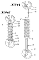
- the return spring is in the in the FIGS. 13 to 17 illustrated third embodiment, a compression spring 6.
- the lock cylinder forms a chamber 9.
- the housing element 15 is connected by means of a fastening screw 8, which forms a fastening pin, with the flange portion 3 of the lock cylinder.
- the fastening screw 8 engages through a fastening eye 29 of a piston 28.
- the piston 28 protrudes from a support surface 33 and engages in a cavity 32 of a cylinder 30 a.
- the cylinder 30 also protrudes from a support surface 34.
- the support surface 34 is formed by a bearing shell 31 which is clipped onto the eccentric pin 7.
- the helical gear compression spring 6 is located on the lateral surface of the cylinder 30.
- the end 6 'of the helical compression spring is supported on the support surface 33 of the eye 29 and the end 6 "of the return spring 6 facing away from it on the support surface 34 of the bearing shell 31.
- the length of the piston 28 and the cylinder 30 is dimensioned such that in the in FIG. 15 shown 180 ° twisted position from the neutral position of the piston 28 completely in the cylinder 30 is stuck. In the in FIG. 14 shown neutral position is only the end portion of the piston 28 in the cavity 32 of the cylinder 30th
- the piston 28 may be formed by a casting, in particular by a plastic injection-molded part and be mounted with the interposition of a bearing sleeve 10 on the mounting pin 8.
- the cylinder 30 may be made of plastic. He may also be stored with the interposition of a bearing sleeve on the eccentric pin 7.
- the bearing shell 31 surrounds the eccentric pin 7 by a peripheral region which is greater than 180 °, so that the diametral of the two arms of the bearing shell is included.
Landscapes
- Engineering & Computer Science (AREA)
- Mechanical Engineering (AREA)
- Closing And Opening Devices For Wings, And Checks For Wings (AREA)
- Lighting Device Outwards From Vehicle And Optical Signal (AREA)
- Gear-Shifting Mechanisms (AREA)
- Power-Operated Mechanisms For Wings (AREA)
- Lock And Its Accessories (AREA)
Claims (15)
- Cylindre de serrure, avec un boîtier (1) présentant un tronçon de palier (2) et un tronçon de rebord (3), un coeur de cylindre (4), monté libre en rotation dans le tronçon de palier (2), relié de manière solidaire en rotation à un élément de fermeture (5), et avec un ressort de rappel (6), fixé d'un côté sur le boîtier (1) et de l'autre côté agissant sur un tourillon excentrique (7) disposé de manière excentrique par rapport à l'axe de rotation du coeur de cylindre (4), pour de nouveau rappeler en rotation à une position neutre le coeur de cylindre (4) ayant été tourné hors de la position neutre, caractérisé en ce qu'une première extrémité (6') du ressort de rappel agit sur un tourillon de fixation (8), disposé dans une chambre (9), du tronçon de rebord (3), et qu'une deuxième extrémité (6") agit sur le tourillon excentrique (7) du coeur de cylindre (3).
- Cylindre de serrure selon la revendication 1, caractérisé en ce que le ressort de rappel (6) est un ressort de traction, dont les extrémités sont des extrémités en crochet, une extrémité en crochet (6') entourant le tourillon de fixation (8) disposé dans la chambre (9) du tronçon de rebord (3), et l'autre extrémité en crochet (6") entourant le tronçon excentrique (7) du coeur de cylindre.
- Cylindre de serrure selon l'une des revendications précédentes, caractérisé en ce que le ressort (6) est un ressort hélicoïdal, les spires d'hélicoïde du ressort (6), dans la position neutre ou dans une position du coeur de cylindre (4), tournée à 180° par rapport à celle-ci, étant situées dans la chambre (9).
- Cylindre de serrure selon l'une des revendications précédentes, caractérisé en ce que le tourillon excentrique (7) est la liaison de deux tronçons (4', 44") du coeur de cylindre (4).
- Cylindre de serrure selon l'une des revendications précédentes, caractérisé en ce que les extrémités en crochet (6', 6") du ressort (6) sont chacune situées sur des manchons de palier (10), associés, libres en rotation, au tourillon de fixation (8) ou aux tourillons excentriques (7), les manchons de palier (10) présentant en particulier chacun une fente axiale, pour pouvoir être placés, en particulier montés par clipsage, sur le tourillon de fixation (8), ou les tourillons excentriques (7), et en particulier constituant des brides (11, 12) faisant saillie radialement sur les bords de fente et/ou constituant une pluralité de nervures (13) s'étendant sensiblement en direction axiale, disposées sur la surface d'enveloppe du manchon de palier (10) et constituant chacune un évidement médian, dans lequel l'extrémité en crochet (6', 6") du ressort de rappel (6) s'insère.
- Cylindre de serrure selon la revendication 1, caractérisé en ce que le ressort de rappel (6) est un ressort de compression, dont les extrémités (6', 6") sont chacune soutenues sur une face d'appui (33, 34), les faces d'appui (33, 34) étant constituées chacune par un anneau (29) ou une coque de palier (31), agissant sur le tourillon excentrique (7) ou le tourillon de fixation (8), la coque de palier (31) étant en particulier montée par clipsage sur le tourillon excentrique (7) ou les tourillons de fixation (8).
- Cylindre de serrure selon l'une des revendications précédentes, caractérisé en ce que la coque de palier (31), ou l'anneau (29), est formé/e par un piston (28) ou un cylindre (30) d'une unité de piston à cylindre.
- Cylindre de serrure selon l'une des revendications 6 ou 7, caractérisé en ce que le ressort hélicoïdal de compression (6) est disposé sur la surface d'enveloppe extérieure d'un cylindre (30) dans lequel est enfiché un piston (28).
- Cylindre de serrure selon la revendication 8, caractérisé en ce que le piston (28), ou la cavité (32) du cylindre (30), présente une forme de section transversale en croix.
- Cylindre de serrure selon l'une des revendications précédentes, caractérisé en ce que le ressort de rappel (6) agit sur le coeur de cylindre (4), de manière que, dans une position en rotation à peu près à 180° par rapport à la position neutre, il prenne une position de point mort, et en outre caractérisé par un ressort complémentaire (22), entrant ensuite en action dans la zone de la position de point mort, appliquant sur le coeur de cylindre (1) un couple de rotation agissant dans le sens de l'écartement par rapport à la position de point mort.
- Cylindre de serrure selon la revendication 10, caractérisé en ce que le ressort complémentaire (22) est un ressort étrier, présentant en particulier sensiblement une forme de bulbe.
- Cylindre de serrure selon l'une des revendications 10 ou 11, caractérisé en ce que le ressort complémentaire (22) coopère avec une butée (24) diamétralement opposée au tourillon excentrique.
- Cylindre de serrure selon l'une des revendications 10 à 12, caractérisé en ce qu'une pointe (22') du ressort complémentaire (22) coopère avec la surface périphérique d'un galet (25) monté à rotation sur la butée (24).
- Cylindre de serrure selon la revendication 13, caractérisé en ce qu'un tronçon de fixation, opposé à la pointe (22') du ressort (22) est fixé, avec un espace de jeu en flexion, au moyen d'une fixation à ressort (21), sur la paroi d'une chambre (9) du tronçon de rebord (3).
- Cylindre de serrure selon l'une des revendications 10 à 14, caractérisé par une vis de fixation (23), traversant l'espace intérieur d'étrier du ressort (22).
Applications Claiming Priority (2)
| Application Number | Priority Date | Filing Date | Title |
|---|---|---|---|
| DE102008005179 | 2008-01-19 | ||
| DE102008029686.4A DE102008029686B4 (de) | 2008-01-19 | 2008-06-23 | Schließzylinder mit selbsttätiger Rückstellung des Schließgliedes |
Publications (2)
| Publication Number | Publication Date |
|---|---|
| EP2088263A1 EP2088263A1 (fr) | 2009-08-12 |
| EP2088263B1 true EP2088263B1 (fr) | 2010-06-23 |
Family
ID=40785995
Family Applications (1)
| Application Number | Title | Priority Date | Filing Date |
|---|---|---|---|
| EP09150499A Active EP2088263B1 (fr) | 2008-01-19 | 2009-01-14 | Serrure cylindrique à retour automatique du panneton |
Country Status (4)
| Country | Link |
|---|---|
| EP (1) | EP2088263B1 (fr) |
| AT (1) | ATE472025T1 (fr) |
| DE (3) | DE102008029686B4 (fr) |
| ES (1) | ES2345421T3 (fr) |
Cited By (1)
| Publication number | Priority date | Publication date | Assignee | Title |
|---|---|---|---|---|
| EP2568101A2 (fr) | 2011-09-12 | 2013-03-13 | Assa Abloy Sicherheitstechnik GmbH | Cylindre à pommeau |
Families Citing this family (6)
| Publication number | Priority date | Publication date | Assignee | Title |
|---|---|---|---|---|
| PL2597229T3 (pl) | 2011-11-25 | 2015-10-30 | Cestronics Gmbh | Część sprzęgająca, urządzenie sworzniowe, mechanizm cofający, obudowa wkładki bębenkowej, urządzenie bębenkowe, wkładka zamkowa bębenkowa i zamek wpuszczany oraz odnośny sposób cofania i montażu |
| DE102012108432B4 (de) | 2012-06-13 | 2019-05-09 | Uhlmann & Zacher Gmbh | Antipanikzylinder |
| DE102012108998B3 (de) * | 2012-09-24 | 2014-05-22 | Uhlmann & Zacher Gmbh | Antipanikzylinder |
| EP2738325B1 (fr) * | 2012-11-30 | 2017-06-14 | SimonsVoss Technologies GmbH | Cylindre anti-panique |
| DE102013001501C5 (de) * | 2013-01-29 | 2017-03-16 | Klaus Meister | Rückstellsystem für die Schließnase elektronischer Schließsysteme |
| FR3080894B1 (fr) * | 2018-05-04 | 2021-11-26 | Latecoere | Procede et systeme de maintien a came d'un arbre en positionnement bistable |
Family Cites Families (7)
| Publication number | Priority date | Publication date | Assignee | Title |
|---|---|---|---|---|
| DE1553510A1 (de) * | 1965-01-15 | 1969-08-21 | Witte & Co Ewald | Zylinderschloss zur Betaetigung,insbesondere von Kraftfahrzeugschloessern |
| FR2510647A1 (fr) * | 1981-07-30 | 1983-02-04 | Neiman Sa | Verrou a levier ou came |
| JP3298737B2 (ja) * | 1994-04-28 | 2002-07-08 | 株式会社アルファ | シリンダ錠装置のキーシリンダ自動復帰装置 |
| DE10243615B4 (de) | 2002-09-19 | 2004-09-23 | Meister, Klaus, Dr. | Elektronisches Zylindersystem für Panikschlösser |
| DE10316522B3 (de) | 2003-04-10 | 2004-07-08 | Seccor High Security Gmbh | Automatisches Rückstellsystem für elektronische Schließsysteme im Einsatz mit Panikschlössern |
| DE102004048231B4 (de) | 2004-10-04 | 2006-08-03 | Simonsvoss Technologies Ag | Automatische Rückstellvorrichtung |
| DE102006020614B4 (de) | 2005-04-29 | 2017-02-02 | Mehmet Sancak | Schloss mit automatischer Rückstellung des Schließbarts |
-
2008
- 2008-06-23 DE DE102008029686.4A patent/DE102008029686B4/de not_active Expired - Fee Related
-
2009
- 2009-01-14 ES ES09150499T patent/ES2345421T3/es active Active
- 2009-01-14 DE DE202009017880U patent/DE202009017880U1/de not_active Expired - Lifetime
- 2009-01-14 AT AT09150499T patent/ATE472025T1/de active
- 2009-01-14 DE DE502009000032T patent/DE502009000032D1/de active Active
- 2009-01-14 EP EP09150499A patent/EP2088263B1/fr active Active
Cited By (2)
| Publication number | Priority date | Publication date | Assignee | Title |
|---|---|---|---|---|
| EP2568101A2 (fr) | 2011-09-12 | 2013-03-13 | Assa Abloy Sicherheitstechnik GmbH | Cylindre à pommeau |
| DE102011113796A1 (de) | 2011-09-12 | 2013-03-14 | Assa Abloy Sicherheitstechnik Gmbh | Knaufzylinder |
Also Published As
| Publication number | Publication date |
|---|---|
| EP2088263A1 (fr) | 2009-08-12 |
| DE102008029686A1 (de) | 2009-07-23 |
| DE202009017880U1 (de) | 2010-08-12 |
| DE102008029686B4 (de) | 2016-07-28 |
| ATE472025T1 (de) | 2010-07-15 |
| ES2345421T3 (es) | 2010-09-22 |
| DE502009000032D1 (de) | 2010-08-05 |
Similar Documents
| Publication | Publication Date | Title |
|---|---|---|
| DE102008029686B4 (de) | Schließzylinder mit selbsttätiger Rückstellung des Schließgliedes | |
| DE102011102159B4 (de) | Modularer Schließzylinder | |
| DE20204126U1 (de) | Zielgerät für Verriegelungsnägel | |
| EP3153648A1 (fr) | Cadenas | |
| DE102009023561A1 (de) | Vorhangschloss | |
| AT11207U1 (de) | Kupplungsvorrichtung mit panikfunktion für elektromechanische feststellvorrichtungen | |
| DE102012003168A1 (de) | Schliesszylinder | |
| EP2410110B1 (fr) | Cylindre de fermeture, notamment cylindre double doté d'un organe de fermeture à roue libre | |
| DE102012100424B4 (de) | Vorrichtung für das Steuern der Schliessfolge von zweiflügeligen Schwenktüren | |
| EP2302272B1 (fr) | Cartouche de soupape | |
| DE29722488U1 (de) | Vorreiberverschluß für dickwandige Türen, Klappen o.dgl. | |
| DE102010017388A1 (de) | Vorrichtung zur Kupplung und Entkupplung eines Türaußendrückers | |
| EP2299041A2 (fr) | Dispositif d'amortissement pour éléments de meuble mobiles | |
| EP1987217A1 (fr) | Dispositif de fixation d'une poignée de porte ou de fenêtre | |
| DE102008034070A1 (de) | Schließzylinder mit federkraftunterstützter Zylinderkernrückstellung | |
| DE10041652B4 (de) | Abstandsveränderlicher Schließbügel für Drehfallenverschlüsse | |
| DE102019113666A1 (de) | Schließzylinder | |
| EP3741933B1 (fr) | Dispositif de fermeture | |
| DE10329414B4 (de) | Schließvorrichtung | |
| DE102009051594B4 (de) | Haken, insbesondere für Sicherheitseinrichtungen | |
| DE19822030A1 (de) | Zweiteiliger Drückerstift | |
| EP1887151B1 (fr) | Support angulaire | |
| EP2597229A1 (fr) | Elément d'embrayage, système de boulon, mécanisme de rappel, boîtier de cylindre, dispositif de cylindre, cylindre de fermeture et serrure à mortaiser ainsi que procédé de rappel et de montage associés | |
| EP3636863B1 (fr) | Fixation de joint | |
| EP0606877A2 (fr) | Ferrure pour une serrure avec un pêne demi-tour et un pêne dormant |
Legal Events
| Date | Code | Title | Description |
|---|---|---|---|
| PUAI | Public reference made under article 153(3) epc to a published international application that has entered the european phase |
Free format text: ORIGINAL CODE: 0009012 |
|
| AK | Designated contracting states |
Kind code of ref document: A1 Designated state(s): AT BE BG CH CY CZ DE DK EE ES FI FR GB GR HR HU IE IS IT LI LT LU LV MC MK MT NL NO PL PT RO SE SI SK TR |
|
| AX | Request for extension of the european patent |
Extension state: AL BA RS |
|
| RTI1 | Title (correction) |
Free format text: LOCK CYLINDER WITH WITH AUTOMATIC RETURN OF THE LOCK CAM |
|
| 17P | Request for examination filed |
Effective date: 20091125 |
|
| RIC1 | Information provided on ipc code assigned before grant |
Ipc: E05B 15/04 20060101ALI20100119BHEP Ipc: E05B 9/04 20060101AFI20100119BHEP |
|
| GRAP | Despatch of communication of intention to grant a patent |
Free format text: ORIGINAL CODE: EPIDOSNIGR1 |
|
| GRAS | Grant fee paid |
Free format text: ORIGINAL CODE: EPIDOSNIGR3 |
|
| AKX | Designation fees paid |
Designated state(s): AT BE BG CH CY CZ DE DK EE ES FI FR GB GR HR HU IE IS IT LI LT LU LV MC MK MT NL NO PL PT RO SE SI SK TR |
|
| GRAA | (expected) grant |
Free format text: ORIGINAL CODE: 0009210 |
|
| AK | Designated contracting states |
Kind code of ref document: B1 Designated state(s): AT BE BG CH CY CZ DE DK EE ES FI FR GB GR HR HU IE IS IT LI LT LU LV MC MK MT NL NO PL PT RO SE SI SK TR |
|
| REG | Reference to a national code |
Ref country code: CH Ref legal event code: EP |
|
| REG | Reference to a national code |
Ref country code: IE Ref legal event code: FG4D Free format text: LANGUAGE OF EP DOCUMENT: GERMAN |
|
| REG | Reference to a national code |
Ref country code: NL Ref legal event code: T3 |
|
| REF | Corresponds to: |
Ref document number: 502009000032 Country of ref document: DE Date of ref document: 20100805 Kind code of ref document: P |
|
| REG | Reference to a national code |
Ref country code: CH Ref legal event code: NV Representative=s name: R. A. EGLI & CO. PATENTANWAELTE |
|
| REG | Reference to a national code |
Ref country code: ES Ref legal event code: FG2A Ref document number: 2345421 Country of ref document: ES Kind code of ref document: T3 |
|
| PG25 | Lapsed in a contracting state [announced via postgrant information from national office to epo] |
Ref country code: SE Free format text: LAPSE BECAUSE OF FAILURE TO SUBMIT A TRANSLATION OF THE DESCRIPTION OR TO PAY THE FEE WITHIN THE PRESCRIBED TIME-LIMIT Effective date: 20100623 Ref country code: LT Free format text: LAPSE BECAUSE OF FAILURE TO SUBMIT A TRANSLATION OF THE DESCRIPTION OR TO PAY THE FEE WITHIN THE PRESCRIBED TIME-LIMIT Effective date: 20100623 Ref country code: NO Free format text: LAPSE BECAUSE OF FAILURE TO SUBMIT A TRANSLATION OF THE DESCRIPTION OR TO PAY THE FEE WITHIN THE PRESCRIBED TIME-LIMIT Effective date: 20100923 |
|
| LTIE | Lt: invalidation of european patent or patent extension |
Effective date: 20100623 |
|
| PG25 | Lapsed in a contracting state [announced via postgrant information from national office to epo] |
Ref country code: FI Free format text: LAPSE BECAUSE OF FAILURE TO SUBMIT A TRANSLATION OF THE DESCRIPTION OR TO PAY THE FEE WITHIN THE PRESCRIBED TIME-LIMIT Effective date: 20100623 Ref country code: HR Free format text: LAPSE BECAUSE OF FAILURE TO SUBMIT A TRANSLATION OF THE DESCRIPTION OR TO PAY THE FEE WITHIN THE PRESCRIBED TIME-LIMIT Effective date: 20100623 Ref country code: LV Free format text: LAPSE BECAUSE OF FAILURE TO SUBMIT A TRANSLATION OF THE DESCRIPTION OR TO PAY THE FEE WITHIN THE PRESCRIBED TIME-LIMIT Effective date: 20100623 Ref country code: SI Free format text: LAPSE BECAUSE OF FAILURE TO SUBMIT A TRANSLATION OF THE DESCRIPTION OR TO PAY THE FEE WITHIN THE PRESCRIBED TIME-LIMIT Effective date: 20100623 |
|
| PG25 | Lapsed in a contracting state [announced via postgrant information from national office to epo] |
Ref country code: PL Free format text: LAPSE BECAUSE OF FAILURE TO SUBMIT A TRANSLATION OF THE DESCRIPTION OR TO PAY THE FEE WITHIN THE PRESCRIBED TIME-LIMIT Effective date: 20100623 |
|
| PG25 | Lapsed in a contracting state [announced via postgrant information from national office to epo] |
Ref country code: EE Free format text: LAPSE BECAUSE OF FAILURE TO SUBMIT A TRANSLATION OF THE DESCRIPTION OR TO PAY THE FEE WITHIN THE PRESCRIBED TIME-LIMIT Effective date: 20100623 |
|
| REG | Reference to a national code |
Ref country code: IE Ref legal event code: FD4D |
|
| PG25 | Lapsed in a contracting state [announced via postgrant information from national office to epo] |
Ref country code: SK Free format text: LAPSE BECAUSE OF FAILURE TO SUBMIT A TRANSLATION OF THE DESCRIPTION OR TO PAY THE FEE WITHIN THE PRESCRIBED TIME-LIMIT Effective date: 20100623 Ref country code: IS Free format text: LAPSE BECAUSE OF FAILURE TO SUBMIT A TRANSLATION OF THE DESCRIPTION OR TO PAY THE FEE WITHIN THE PRESCRIBED TIME-LIMIT Effective date: 20101023 Ref country code: CZ Free format text: LAPSE BECAUSE OF FAILURE TO SUBMIT A TRANSLATION OF THE DESCRIPTION OR TO PAY THE FEE WITHIN THE PRESCRIBED TIME-LIMIT Effective date: 20100623 Ref country code: CY Free format text: LAPSE BECAUSE OF FAILURE TO SUBMIT A TRANSLATION OF THE DESCRIPTION OR TO PAY THE FEE WITHIN THE PRESCRIBED TIME-LIMIT Effective date: 20100623 Ref country code: RO Free format text: LAPSE BECAUSE OF FAILURE TO SUBMIT A TRANSLATION OF THE DESCRIPTION OR TO PAY THE FEE WITHIN THE PRESCRIBED TIME-LIMIT Effective date: 20100623 |
|
| PG25 | Lapsed in a contracting state [announced via postgrant information from national office to epo] |
Ref country code: DK Free format text: LAPSE BECAUSE OF FAILURE TO SUBMIT A TRANSLATION OF THE DESCRIPTION OR TO PAY THE FEE WITHIN THE PRESCRIBED TIME-LIMIT Effective date: 20100623 Ref country code: IE Free format text: LAPSE BECAUSE OF FAILURE TO SUBMIT A TRANSLATION OF THE DESCRIPTION OR TO PAY THE FEE WITHIN THE PRESCRIBED TIME-LIMIT Effective date: 20100623 |
|
| PLBE | No opposition filed within time limit |
Free format text: ORIGINAL CODE: 0009261 |
|
| STAA | Information on the status of an ep patent application or granted ep patent |
Free format text: STATUS: NO OPPOSITION FILED WITHIN TIME LIMIT |
|
| PG25 | Lapsed in a contracting state [announced via postgrant information from national office to epo] |
Ref country code: GR Free format text: LAPSE BECAUSE OF FAILURE TO SUBMIT A TRANSLATION OF THE DESCRIPTION OR TO PAY THE FEE WITHIN THE PRESCRIBED TIME-LIMIT Effective date: 20100924 |
|
| 26N | No opposition filed |
Effective date: 20110324 |
|
| REG | Reference to a national code |
Ref country code: DE Ref legal event code: R097 Ref document number: 502009000032 Country of ref document: DE Effective date: 20110323 |
|
| PG25 | Lapsed in a contracting state [announced via postgrant information from national office to epo] |
Ref country code: MC Free format text: LAPSE BECAUSE OF NON-PAYMENT OF DUE FEES Effective date: 20110131 |
|
| PG25 | Lapsed in a contracting state [announced via postgrant information from national office to epo] |
Ref country code: MT Free format text: LAPSE BECAUSE OF FAILURE TO SUBMIT A TRANSLATION OF THE DESCRIPTION OR TO PAY THE FEE WITHIN THE PRESCRIBED TIME-LIMIT Effective date: 20100623 |
|
| PGFP | Annual fee paid to national office [announced via postgrant information from national office to epo] |
Ref country code: TR Payment date: 20120109 Year of fee payment: 4 |
|
| PG25 | Lapsed in a contracting state [announced via postgrant information from national office to epo] |
Ref country code: LU Free format text: LAPSE BECAUSE OF NON-PAYMENT OF DUE FEES Effective date: 20110114 |
|
| PG25 | Lapsed in a contracting state [announced via postgrant information from national office to epo] |
Ref country code: PT Free format text: LAPSE BECAUSE OF NON-PAYMENT OF DUE FEES Effective date: 20100623 |
|
| PG25 | Lapsed in a contracting state [announced via postgrant information from national office to epo] |
Ref country code: BG Free format text: LAPSE BECAUSE OF FAILURE TO SUBMIT A TRANSLATION OF THE DESCRIPTION OR TO PAY THE FEE WITHIN THE PRESCRIBED TIME-LIMIT Effective date: 20100923 |
|
| PG25 | Lapsed in a contracting state [announced via postgrant information from national office to epo] |
Ref country code: HU Free format text: LAPSE BECAUSE OF FAILURE TO SUBMIT A TRANSLATION OF THE DESCRIPTION OR TO PAY THE FEE WITHIN THE PRESCRIBED TIME-LIMIT Effective date: 20100623 |
|
| REG | Reference to a national code |
Ref country code: DE Ref legal event code: R082 Ref document number: 502009000032 Country of ref document: DE Representative=s name: WITTE, WELLER & PARTNER PATENTANWAELTE MBB, DE |
|
| REG | Reference to a national code |
Ref country code: FR Ref legal event code: PLFP Year of fee payment: 8 |
|
| REG | Reference to a national code |
Ref country code: FR Ref legal event code: PLFP Year of fee payment: 9 |
|
| PG25 | Lapsed in a contracting state [announced via postgrant information from national office to epo] |
Ref country code: TR Free format text: LAPSE BECAUSE OF NON-PAYMENT OF DUE FEES Effective date: 20140114 |
|
| REG | Reference to a national code |
Ref country code: FR Ref legal event code: PLFP Year of fee payment: 10 |
|
| PGFP | Annual fee paid to national office [announced via postgrant information from national office to epo] |
Ref country code: GB Payment date: 20250122 Year of fee payment: 17 |
|
| REG | Reference to a national code |
Ref country code: CH Ref legal event code: U11 Free format text: ST27 STATUS EVENT CODE: U-0-0-U10-U11 (AS PROVIDED BY THE NATIONAL OFFICE) Effective date: 20260201 |
|
| PGFP | Annual fee paid to national office [announced via postgrant information from national office to epo] |
Ref country code: NL Payment date: 20260121 Year of fee payment: 18 |
|
| PGFP | Annual fee paid to national office [announced via postgrant information from national office to epo] |
Ref country code: ES Payment date: 20260217 Year of fee payment: 18 |
|
| PGFP | Annual fee paid to national office [announced via postgrant information from national office to epo] |
Ref country code: DE Payment date: 20260120 Year of fee payment: 18 |
|
| PGFP | Annual fee paid to national office [announced via postgrant information from national office to epo] |
Ref country code: AT Payment date: 20260123 Year of fee payment: 18 |
|
| PGFP | Annual fee paid to national office [announced via postgrant information from national office to epo] |
Ref country code: IT Payment date: 20260126 Year of fee payment: 18 Ref country code: BE Payment date: 20260121 Year of fee payment: 18 |
|
| PGFP | Annual fee paid to national office [announced via postgrant information from national office to epo] |
Ref country code: FR Payment date: 20260121 Year of fee payment: 18 |
|
| PGFP | Annual fee paid to national office [announced via postgrant information from national office to epo] |
Ref country code: CH Payment date: 20260201 Year of fee payment: 18 |