EP2299122A2 - Ventilateur à dissipation thermique - Google Patents
Ventilateur à dissipation thermique Download PDFInfo
- Publication number
- EP2299122A2 EP2299122A2 EP10009327A EP10009327A EP2299122A2 EP 2299122 A2 EP2299122 A2 EP 2299122A2 EP 10009327 A EP10009327 A EP 10009327A EP 10009327 A EP10009327 A EP 10009327A EP 2299122 A2 EP2299122 A2 EP 2299122A2
- Authority
- EP
- European Patent Office
- Prior art keywords
- heat dissipating
- housing
- dissipating fan
- impeller
- air outlet
- Prior art date
- Legal status (The legal status is an assumption and is not a legal conclusion. Google has not performed a legal analysis and makes no representation as to the accuracy of the status listed.)
- Granted
Links
Images



Classifications
-
- F—MECHANICAL ENGINEERING; LIGHTING; HEATING; WEAPONS; BLASTING
- F04—POSITIVE - DISPLACEMENT MACHINES FOR LIQUIDS; PUMPS FOR LIQUIDS OR ELASTIC FLUIDS
- F04D—NON-POSITIVE-DISPLACEMENT PUMPS
- F04D25/00—Pumping installations or systems
- F04D25/02—Units comprising pumps and their driving means
- F04D25/06—Units comprising pumps and their driving means the pump being electrically driven
- F04D25/0606—Units comprising pumps and their driving means the pump being electrically driven the electric motor being specially adapted for integration in the pump
- F04D25/0613—Units comprising pumps and their driving means the pump being electrically driven the electric motor being specially adapted for integration in the pump the electric motor being of the inside-out type, i.e. the rotor is arranged radially outside a central stator
- F04D25/0633—Details of the magnetic circuit
-
- F—MECHANICAL ENGINEERING; LIGHTING; HEATING; WEAPONS; BLASTING
- F04—POSITIVE - DISPLACEMENT MACHINES FOR LIQUIDS; PUMPS FOR LIQUIDS OR ELASTIC FLUIDS
- F04D—NON-POSITIVE-DISPLACEMENT PUMPS
- F04D27/00—Control, e.g. regulation, of pumps, pumping installations or pumping systems specially adapted for elastic fluids
- F04D27/004—Control, e.g. regulation, of pumps, pumping installations or pumping systems specially adapted for elastic fluids by varying driving speed
-
- F—MECHANICAL ENGINEERING; LIGHTING; HEATING; WEAPONS; BLASTING
- F04—POSITIVE - DISPLACEMENT MACHINES FOR LIQUIDS; PUMPS FOR LIQUIDS OR ELASTIC FLUIDS
- F04D—NON-POSITIVE-DISPLACEMENT PUMPS
- F04D27/00—Control, e.g. regulation, of pumps, pumping installations or pumping systems specially adapted for elastic fluids
- F04D27/008—Stop safety or alarm devices, e.g. stop-and-go control; Disposition of check-valves
-
- F—MECHANICAL ENGINEERING; LIGHTING; HEATING; WEAPONS; BLASTING
- F04—POSITIVE - DISPLACEMENT MACHINES FOR LIQUIDS; PUMPS FOR LIQUIDS OR ELASTIC FLUIDS
- F04D—NON-POSITIVE-DISPLACEMENT PUMPS
- F04D29/00—Details, component parts, or accessories
- F04D29/40—Casings; Connections of working fluid
- F04D29/42—Casings; Connections of working fluid for radial or helico-centrifugal pumps
- F04D29/4206—Casings; Connections of working fluid for radial or helico-centrifugal pumps especially adapted for elastic fluid pumps
- F04D29/4226—Fan casings
- F04D29/4246—Fan casings comprising more than one outlet
-
- F—MECHANICAL ENGINEERING; LIGHTING; HEATING; WEAPONS; BLASTING
- F04—POSITIVE - DISPLACEMENT MACHINES FOR LIQUIDS; PUMPS FOR LIQUIDS OR ELASTIC FLUIDS
- F04D—NON-POSITIVE-DISPLACEMENT PUMPS
- F04D29/00—Details, component parts, or accessories
- F04D29/70—Suction grids; Strainers; Dust separation; Cleaning
- F04D29/701—Suction grids; Strainers; Dust separation; Cleaning especially adapted for elastic fluid pumps
- F04D29/703—Suction grids; Strainers; Dust separation; Cleaning especially adapted for elastic fluid pumps specially for fans, e.g. fan guards
-
- H—ELECTRICITY
- H05—ELECTRIC TECHNIQUES NOT OTHERWISE PROVIDED FOR
- H05K—PRINTED CIRCUITS; CASINGS OR CONSTRUCTIONAL DETAILS OF ELECTRIC APPARATUS; MANUFACTURE OF ASSEMBLAGES OF ELECTRICAL COMPONENTS
- H05K7/00—Constructional details common to different types of electric apparatus
- H05K7/20—Modifications to facilitate cooling, ventilating, or heating
- H05K7/20009—Modifications to facilitate cooling, ventilating, or heating using a gaseous coolant in electronic enclosures
- H05K7/20136—Forced ventilation, e.g. by fans
- H05K7/20172—Fan mounting or fan specifications
-
- Y—GENERAL TAGGING OF NEW TECHNOLOGICAL DEVELOPMENTS; GENERAL TAGGING OF CROSS-SECTIONAL TECHNOLOGIES SPANNING OVER SEVERAL SECTIONS OF THE IPC; TECHNICAL SUBJECTS COVERED BY FORMER USPC CROSS-REFERENCE ART COLLECTIONS [XRACs] AND DIGESTS
- Y02—TECHNOLOGIES OR APPLICATIONS FOR MITIGATION OR ADAPTATION AGAINST CLIMATE CHANGE
- Y02B—CLIMATE CHANGE MITIGATION TECHNOLOGIES RELATED TO BUILDINGS, e.g. HOUSING, HOUSE APPLIANCES OR RELATED END-USER APPLICATIONS
- Y02B30/00—Energy efficient heating, ventilation or air conditioning [HVAC]
- Y02B30/70—Efficient control or regulation technologies, e.g. for control of refrigerant flow, motor or heating
Definitions
- the present invention relates to a heat dissipating fan and, more particularly, to a heat dissipating fan with automatic dust removing function.
- Conventional heat dissipating fans generally include a housing having an air inlet and an air outlet.
- An impeller is rotatably mounted in the housing and driven by a driving unit also mounted in the housing to draw in ambient air via the air inlet.
- the air currents drawn into the housing are concentrated before exiting the air outlet to a heat source in an electronic product. The temperature during operation of the heat source is thus lowered.
- dust carried by the air currents is liable to accumulate inside the housing at the air inlet, the air outlet, the blades of the impeller, etc., adversely affecting the air input and/or air output and thus, adversely affecting the heat dissipating effect.
- FIG. 1 shows a heat dissipating fan 9 which includes a housing 91 having an air inlet 911 and an air outlet 912.
- An impeller 92 is mounted in the housing 91.
- a plurality of fins 93 is mounted in the air outlet 912. Air currents can be driven by the impeller 92 into the housing 91 via the air inlet 911. The air currents pass through the fins 93 and the air outlet 912 to a heat source of an electronic product.
- An example of such a blower fan 9 is disclosed in Taiwan Patent No. I229254 .
- dust is liable to accumulate inside the housing 91 after a period of time. Since the spacing between the fins 93 is small, the dust is liable to accumulate between the fins 93, significantly reducing the air output and requiring regular manual cleaning.
- An objective of the present invention is to provide a heat dissipating fan that can remove dust automatically.
- Another objective of the present invention is to provide a heat dissipating fan with reliable input and output of air by automatically removing dust.
- a heat dissipating fan which includes a housing having a base and a sidewall coupled to the base.
- the sidewall defines a compartment.
- the housing further includes an air inlet, an air outlet and a dust channel.
- the air inlet, the air outlet and the dust channel are in communication with the compartment.
- a stator is coupled to the base of the housing.
- An impeller is rotatably coupled to the stator.
- a control element includes a driving circuit electrically connected to the stator and a rotating direction control circuit electrically connected to the driving circuit.
- a heat dissipating fan in another preferred aspect, includes a housing having a base and a lateral wall coupled to the base.
- the lateral wall defines a compartment.
- the lateral wall includes an air inlet and an air outlet both in communication with the compartment.
- the air inlet also acts as a dust channel.
- a stator is coupled to the base of the housing.
- An impeller is rotatably coupled to the stator.
- a control element includes a driving circuit electrically connected to the stator and a rotating direction control circuit electrically connected to the driving circuit.
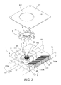
- a heat dissipating fan of a first embodiment generally includes a housing 1, a stator 2, an impeller 3, and a control element 4.
- the housing 1 can be mounted in a desired location of an electronic product, such as a face of a main board inside a computer.
- the stator 2 is mounted in the housing 1.
- the impeller 3 is mounted in the housing 1 and rotatably coupled to the stator 2.
- the control element 4 controls the impeller 3 to rotate either in a direction for generating enough air for heat dissipating purposes or in a reverse direction for dust removing purposes by cooperating with the structure of the housing 1.
- the housing 1 includes a base 11 and a sidewall 12 coupled to a side of the base 11 and defining a compartment 121.
- the sidewall 12 includes an air inlet 122 and an air outlet 123 both in communication with the compartment 121.
- the sidewall 12 further includes a dust channel 124 in communication with the compartment 121. It can be appreciated that the sidewall 12 can include more than one dust channel 124.
- the stator 2 is mounted to the base 11 of the housing 1 and includes a coil unit 21 and a shaft seat 22.
- the coil unit 21 is mounted around or integrally formed with an outer periphery of the shaft seat 22.
- the shaft seat 22 of the stator 2 may be integrally formed on the base 11.
- the impeller 3 includes a hub 31 and a plurality of blades 32.
- the hub 31 is rotatably coupled to the shaft seat 22 of the stator 2.
- the blades 32 are coupled to an outer periphery of the hub 31.
- the control element 4 includes a driving circuit 41 and a rotating direction control circuit 42.
- the driving circuit 41 is electrically connected to the coil unit 21 of the stator 2.
- the rotating direction control circuit 42 is electrically connected to the driving circuit 41.
- the driving circuit 41 and the rotating direction control circuit 42 can be packaged in the same integrated circuit.
- the control element 4 can be integrated into the housing 1. However, the control element 4 can be disposed outside the housing 1 without adversely affecting control of the impeller 3.
- the heat dissipating fan of the first embodiment is engaged with an electronic product with the air outlet 123 of the housing 1 facing a heat source of the electronic product that tends to generate heat during operation.
- the rotating direction control circuit 42 can send a rotating direction control signal to the driving circuit 41 to actuate the coil unit 21 of the stator 2 to create a magnetic field for driving the impeller 3 to rotate in a direction (such as the counterclockwise direction).
- Ambient air currents are drawn in via the air inlet 122.
- the air currents are concentrated by the impeller 3 before passing through the air outlet 123 to the heat source of the electronic product for heat dissipating purposes ( FIG. 3 ).
- the rotating direction control circuit 42 can send another rotating direction control signal to the driving circuit 41 to actuate the coil unit 21 of the stator 2 to create a magnetic field for driving the impeller 3 to rotate in a reverse direction (such as the clockwise direction).
- the air inlet 122 draws in ambient air currents which then exit the housing 1 via the dust channel 124 ( FIG. 4 ).
- the dust accumulated inside the housing 1 can be expelled from the housing 1 together with the air currents, eliminating accumulation of the dust.
- the overall air input and output are not adversely affected, effectively enhancing the heat dissipating effect.
- the rotating direction control circuit 42 can control the timing of rotation of the impeller 3 in the counterclockwise or clockwise direction through the driving circuit 41.
- the heat dissipating fan according to the teachings of the present invention can be set so that the impeller 3 rotates in the counterclockwise direction for a period of time (such as an hour or two) immediately after the heat dissipating fan is turned on. Then, the impeller 3 is controlled to rotate in the clockwise direction for another period of time (such as 10 or 20 minutes) for automatic removal of dust. After the automatic dust removing operation, the impeller 3 is controlled to rotate in the counterclockwise direction for heat dissipating purposes.
- the rotational direction of the impeller 3 can continuously alternate between the counterclockwise and clockwise directions to complete functions of heat dissipating and dust removing.
- the heat dissipating fan according to the teachings of the present invention can be set so that the impeller 3 rotates in the clockwise direction for a period of time for automatic dust removing operation immediately after the heat dissipating fan is turned on. Then, the impeller 3 is controlled to rotate in the counterclockwise direction for heat dissipating purposes.
- the heat dissipating fan of the first embodiment can automatically remove dust without adversely affecting the heat dissipating function.
- accumulation of dust inside the housing 1 is eliminated to avoid adverse effect to the overall heat dissipating effect.
- the heat dissipating effect is thus enhanced, and the service life of the electronic product is prolonged.
- the air outlet 123 of the housing 1 includes opposite first and second end edges 123a and 123b.
- the housing 1 defines a first plane P1 including the first and second end edges 123a and 123b.
- the impeller 3 defines a second plane P2 including a center of the hub 31.
- the second plane P2 is parallel to and spaced from the first plane P1.
- the compartment 121 is divided into an air outlet section 121a and a pressure accumulating section 121b by defining the first and second planes P1 and P2.
- the air outlet section 121 a is located between the first and second planes P1 and P2.
- the pressure accumulating section 121 b and the air outlet section 121a are located on opposite sides of the second plane P2.
- the air outlet 123 is located in the air outlet section 121a.
- the dust channel 124 is located in the pressure accumulating section 121b.
- the dust channel 124 is located away from the air outlet 123.
- the dust channel 124 extends in a direction at an angle with the second plane P2.
- the dust channel 124 can extend in a direction perpendicular or parallel to the second plane P2.
- the extending direction of the dust channel 124 is preferably related to the moving direction of the air currents driven by the impeller 3 rotating in the clockwise direction.
- the dust channel 124 extends in a direction at an angle with the second plane P2 to reduce resistance to the air currents that are driven by the impeller 3 to flow along an inner face of the sidewall 12 into the dust channel 124, assuring smooth dust removal operation.
- a cover 13 can be mounted to the sidewall 12 of the housing 1.
- the cover 13 includes an opening 131 aligned with the air inlet 122.
- the cover 13 covers the compartment 121 over the air inlet 122, so that the air currents generated by the impeller 3 can enter the housing 1 via the opening 131 and the air inlet 122, providing a pressure increasing effect to smoothly guide the air currents to exit the air outlet 123.
- the base 11 of the housing 1 can further include a plurality of auxiliary air inlets 111 aligned with the air inlet 122.
- the air currents generated by the impeller 3 can also enter the housing 1 via the auxiliary air inlets 111, increasing the air input.
- a plurality of fins 14 can be formed in the air outlet 123.
- the fins 14 can be directly formed in the air outlet 123 or integrated as a heat sink mounted to the air outlet 123.
- the fins 14 can absorb the high heat generated by the heat source of the electronic product, providing further enhanced heat dissipating effect while the impeller 3 drives air currents through the air outlet 123.
- a dust guiding pipe 15 can be attached to the dust channel 124 to guide the dust removed from the housing 1 away from the housing 1, assuring the dust removing effect.
- FIGS. 6-8 show a heat dissipating fan of a second embodiment according to the preferred teachings of the present invention.
- the heat dissipating fan includes a housing 5, a stator 6, an impeller 7, and a control element 8.
- the housing 5 is preferably of the blower type, the housing 5 can be of the axial-flow type.
- the stator 6 is mounted in the housing 5.
- the impeller 7 is rotatably coupled to the stator 6.
- the control element 8 controls the impeller 7 to rotate in the clockwise or counterclockwise direction.
- the housing 5 includes a base 51 and a lateral wall 52.
- the base 51 and the lateral wall 52 together define a compartment 521.
- the lateral wall 52 includes an air inlet 522 and an air outlet 523 both in communication with the compartment 521.
- the air inlet 522 can act as a dust channel.
- the stator 6 is mounted to the base 51 of the housing 5 and includes a coil unit 61 and a shaft seat 62.
- the coil unit 61 is mounted around or integrally formed with an outer periphery of the shaft seat 62.
- the shaft seat 62 of the stator 6 may be integrally formed on the base 51.
- the impeller 7 is mounted in the compartment 521 of the housing 5 and preferably of the axial-flow type.
- the impeller 7 includes a hub 71 rotatably coupled to the shaft seat 62 of the stator 6 and a plurality of blades 72 coupled to an outer periphery of the hub 71.
- the control element 8 includes a driving circuit 81 and a rotating direction control circuit 82.
- the driving circuit 81 is electrically connected to the coil unit 61 of the stator 6.
- the rotating direction control circuit 82 is electrically connected to the driving circuit 81.
- the driving circuit 81 and the rotating direction control circuit 82 can be packaged in the same integrated circuit.
- the rotating direction control circuit 82 can send a rotating direction control signal to the driving circuit 81 to drive the impeller 7 to rotate in a direction (such as the counterclockwise direction).
- the air inlet 522 draws in ambient air currents which then exit the air outlet 523 to the heat source of the electronic product for heat dissipating purpose ( FIGS. 6 and 7 ).
- the rotating direction control circuit 82 can send another rotating direction control signal to the driving circuit 81 to drive the impeller 7 to rotate in a reverse direction (such as the clockwise direction).
- the flowing direction of the air currents in the housing 5 driven by the impeller 7 rotating in the clockwise direction is opposite to that of the air currents driven by the impeller 7 rotating in the counterclockwise direction.
- the dust is less likely to accumulate in the housing 5. Rather, the dust is removed from the housing 5 via the air inlet 522 acting as a dust channel. Thus, the dust accumulated in the housing 5 can be expelled ( FIGS. 6 and 8 ).
- the heat dissipating fan of the second embodiment can automatically remove dust to avoid adverse effect to the overall heat dissipating effect resulting from accumulation of the dust in the housing 5 while still providing the original heat dissipating function.
- the air inlet 522 of the housing 5 can be utilized as the dust channel without the need to form a dust channel 124 in the sidewall 12 of the housing 1. The structure of the heat dissipating fan is thus simplified.
- the heat dissipating fans can control the impeller 3, 7 with the rotating direction control circuit 42, 82 of the control element 4, 8 via the driving circuit 41, 81 to rotate in a reverse direction that cooperates with the dust channel 124 (or the air inlet 522 of the second embodiment), allowing effective automatic dust removal of the dust accumulated in the housing 1, 5, and thus providing convenient dust removing operation. Since the dust can be removed automatically, the dust is less likely to accumulate to an unexpected amount in the housing 1, 5, effectively maintaining the air input and output and enhancing the heat dissipating effect.
Landscapes
- Engineering & Computer Science (AREA)
- Mechanical Engineering (AREA)
- General Engineering & Computer Science (AREA)
- Microelectronics & Electronic Packaging (AREA)
- Physics & Mathematics (AREA)
- Thermal Sciences (AREA)
- Cooling Or The Like Of Electrical Apparatus (AREA)
- Structures Of Non-Positive Displacement Pumps (AREA)
Applications Claiming Priority (1)
| Application Number | Priority Date | Filing Date | Title |
|---|---|---|---|
| TW098130216A TWI365254B (en) | 2009-09-08 | 2009-09-08 | Dissipating fan comprises a frame, a stator, a fan |
Publications (3)
| Publication Number | Publication Date |
|---|---|
| EP2299122A2 true EP2299122A2 (fr) | 2011-03-23 |
| EP2299122A3 EP2299122A3 (fr) | 2017-03-01 |
| EP2299122B1 EP2299122B1 (fr) | 2018-03-14 |
Family
ID=43087149
Family Applications (1)
| Application Number | Title | Priority Date | Filing Date |
|---|---|---|---|
| EP10009327.7A Active EP2299122B1 (fr) | 2009-09-08 | 2010-09-08 | Ventilateur à dissipation thermique |
Country Status (3)
| Country | Link |
|---|---|
| EP (1) | EP2299122B1 (fr) |
| JP (1) | JP5200075B2 (fr) |
| TW (1) | TWI365254B (fr) |
Cited By (6)
| Publication number | Priority date | Publication date | Assignee | Title |
|---|---|---|---|---|
| WO2016156043A1 (fr) * | 2015-03-31 | 2016-10-06 | Ebm-Papst St. Georgen Gmbh & Co.Kg | Dispositif ventilateur avec sorties principale et auxiliaire dans le boîtier |
| WO2017055589A1 (fr) * | 2015-09-30 | 2017-04-06 | Elektrosil Systeme Der Elektronik Gmbh | Dispositif de refroidissement compact pourvu d'un ventilateur radial collé sur un corps de refroidissement |
| WO2017191534A1 (fr) * | 2016-05-04 | 2017-11-09 | Fisher & Paykel Healthcare Limited | Système d'assistance respiratoire et ventilateur pour système d'assistance respiratoire |
| CN111258155A (zh) * | 2020-03-31 | 2020-06-09 | 青岛海信激光显示股份有限公司 | 一种激光投影设备 |
| CN112886403A (zh) * | 2021-01-15 | 2021-06-01 | 广州邮电通信设备有限公司 | 一种通信电源配电柜 |
| CN115267268A (zh) * | 2022-05-27 | 2022-11-01 | 苏州联讯仪器有限公司 | 一种芯片测试装置 |
Families Citing this family (5)
| Publication number | Priority date | Publication date | Assignee | Title |
|---|---|---|---|---|
| TWI487841B (zh) * | 2011-05-12 | 2015-06-11 | Adda Corp | 散熱風扇 |
| CN102996483B (zh) * | 2011-09-13 | 2015-07-08 | 宏碁股份有限公司 | 自动排尘风扇装置以及自动排尘风扇装置的排尘方法 |
| TWI505073B (zh) * | 2012-03-22 | 2015-10-21 | Compal Electronics Inc | 電子裝置 |
| JP5931550B2 (ja) * | 2012-04-03 | 2016-06-08 | シャープ株式会社 | 送風装置 |
| TWI537480B (zh) * | 2012-07-09 | 2016-06-11 | 建準電機工業股份有限公司 | 鼓風式散熱扇 |
Citations (1)
| Publication number | Priority date | Publication date | Assignee | Title |
|---|---|---|---|---|
| TW229254B (en) | 1992-08-31 | 1994-09-01 | Torng Chau Plastic Co Ltd | Manufacturing method of ventilation pipe |
Family Cites Families (9)
| Publication number | Priority date | Publication date | Assignee | Title |
|---|---|---|---|---|
| JPS6252300U (fr) * | 1985-09-19 | 1987-04-01 | ||
| JPH02163498A (ja) * | 1988-12-19 | 1990-06-22 | Matsushita Electric Ind Co Ltd | 送風機制御装置 |
| US5381886A (en) * | 1993-06-11 | 1995-01-17 | Hay; Andrew G. | Apparatus and method with improved drive force capability for transporting and metering particulate material |
| JP4230615B2 (ja) * | 1999-06-17 | 2009-02-25 | 高木産業株式会社 | 給湯装置 |
| JP2005214107A (ja) * | 2004-01-30 | 2005-08-11 | Sony Corp | ファン装置 |
| KR200372255Y1 (ko) * | 2004-08-31 | 2005-01-14 | 지아누이 홈 어플라이언스 리미티드 | 선풍기 |
| JP4992287B2 (ja) * | 2006-04-28 | 2012-08-08 | 日本電産株式会社 | モータ |
| JP2008140943A (ja) * | 2006-11-30 | 2008-06-19 | Toshiba Tec Corp | 情報処理装置 |
| TWM335721U (en) * | 2008-02-27 | 2008-07-01 | Inventec Corp | Prepared fan module |
-
2009
- 2009-09-08 TW TW098130216A patent/TWI365254B/zh active
-
2010
- 2010-09-07 JP JP2010200359A patent/JP5200075B2/ja active Active
- 2010-09-08 EP EP10009327.7A patent/EP2299122B1/fr active Active
Patent Citations (1)
| Publication number | Priority date | Publication date | Assignee | Title |
|---|---|---|---|---|
| TW229254B (en) | 1992-08-31 | 1994-09-01 | Torng Chau Plastic Co Ltd | Manufacturing method of ventilation pipe |
Cited By (11)
| Publication number | Priority date | Publication date | Assignee | Title |
|---|---|---|---|---|
| WO2016156043A1 (fr) * | 2015-03-31 | 2016-10-06 | Ebm-Papst St. Georgen Gmbh & Co.Kg | Dispositif ventilateur avec sorties principale et auxiliaire dans le boîtier |
| WO2017055589A1 (fr) * | 2015-09-30 | 2017-04-06 | Elektrosil Systeme Der Elektronik Gmbh | Dispositif de refroidissement compact pourvu d'un ventilateur radial collé sur un corps de refroidissement |
| CN108474384A (zh) * | 2015-09-30 | 2018-08-31 | 电子系统股份有限公司 | 具有粘附性地结合散热器的径向风扇的紧凑冷却装置 |
| US11181124B2 (en) | 2015-09-30 | 2021-11-23 | Elektrosil Gmbh | Compact cooling device with radial fan adhesively bonded to a heat sink |
| WO2017191534A1 (fr) * | 2016-05-04 | 2017-11-09 | Fisher & Paykel Healthcare Limited | Système d'assistance respiratoire et ventilateur pour système d'assistance respiratoire |
| US11173263B2 (en) | 2016-05-04 | 2021-11-16 | Fisher & Paykel Healthcare Limited | Respiratory support system and blower for respiratory support system |
| US12343474B2 (en) | 2016-05-04 | 2025-07-01 | Fisher & Paykel Healthcare Limited | Respiratory support system and blower for respiratory support system |
| CN111258155A (zh) * | 2020-03-31 | 2020-06-09 | 青岛海信激光显示股份有限公司 | 一种激光投影设备 |
| CN111258155B (zh) * | 2020-03-31 | 2022-11-22 | 青岛海信激光显示股份有限公司 | 一种激光投影设备 |
| CN112886403A (zh) * | 2021-01-15 | 2021-06-01 | 广州邮电通信设备有限公司 | 一种通信电源配电柜 |
| CN115267268A (zh) * | 2022-05-27 | 2022-11-01 | 苏州联讯仪器有限公司 | 一种芯片测试装置 |
Also Published As
| Publication number | Publication date |
|---|---|
| JP5200075B2 (ja) | 2013-05-15 |
| TWI365254B (en) | 2012-06-01 |
| EP2299122A3 (fr) | 2017-03-01 |
| JP2011058495A (ja) | 2011-03-24 |
| EP2299122B1 (fr) | 2018-03-14 |
| TW201109528A (en) | 2011-03-16 |
Similar Documents
| Publication | Publication Date | Title |
|---|---|---|
| US9429167B2 (en) | Heat dissipating fan | |
| EP2299122B1 (fr) | Ventilateur à dissipation thermique | |
| US9399999B2 (en) | Heat dissipating fan | |
| US8702401B2 (en) | Cooling fan and housing thereof | |
| US6132170A (en) | Miniature heat dissipating fans with minimized thickness | |
| US20120213650A1 (en) | Cooling Fan with Dual Rotation Directions | |
| JP4432989B2 (ja) | 遠心羽根車、ファン装置及び電子機器 | |
| US8974194B2 (en) | Advection-type fan and an impeller thereof | |
| US11162498B2 (en) | Fan | |
| EP2525100A1 (fr) | Ventilateur de type advection | |
| EP2466143A2 (fr) | Module de ventilateur | |
| EP1625282A1 (fr) | Ventilateur centrifuge | |
| JP2008306001A (ja) | 冷却装置および電子機器 | |
| US20060006745A1 (en) | Integrated blower for cooling device | |
| US6869269B2 (en) | Fan device with increased airflow output | |
| JP5048701B2 (ja) | 電動送風機及び電動掃除機 | |
| JP2001271796A (ja) | 電動送風機 | |
| CN102022355B (zh) | 离心式散热风扇 | |
| CN115702541A (zh) | 电机组件和包括电机组件的吸尘器 | |
| US20080232961A1 (en) | Fan and fan frame thereof | |
| JP4670285B2 (ja) | インペラ及びそれを備えた送風ファン | |
| JP2009127612A (ja) | ファンモータのベンチュリー構造 | |
| JP2006177235A (ja) | インペラ及びそれを備えた送風ファン | |
| CN101044324B (zh) | 风扇定子 | |
| JP2002371996A (ja) | 送風機及び送風機を有する換気扇 |
Legal Events
| Date | Code | Title | Description |
|---|---|---|---|
| PUAI | Public reference made under article 153(3) epc to a published international application that has entered the european phase |
Free format text: ORIGINAL CODE: 0009012 |
|
| AK | Designated contracting states |
Kind code of ref document: A2 Designated state(s): AL AT BE BG CH CY CZ DE DK EE ES FI FR GB GR HR HU IE IS IT LI LT LU LV MC MK MT NL NO PL PT RO SE SI SK SM TR |
|
| AX | Request for extension of the european patent |
Extension state: BA ME RS |
|
| PUAL | Search report despatched |
Free format text: ORIGINAL CODE: 0009013 |
|
| AK | Designated contracting states |
Kind code of ref document: A3 Designated state(s): AL AT BE BG CH CY CZ DE DK EE ES FI FR GB GR HR HU IE IS IT LI LT LU LV MC MK MT NL NO PL PT RO SE SI SK SM TR |
|
| AX | Request for extension of the european patent |
Extension state: BA ME RS |
|
| RIC1 | Information provided on ipc code assigned before grant |
Ipc: F04D 29/70 20060101ALI20170126BHEP Ipc: F04D 27/02 20060101ALI20170126BHEP Ipc: F04D 29/42 20060101ALI20170126BHEP Ipc: H01L 23/467 20060101ALI20170126BHEP Ipc: H05K 7/20 20060101ALI20170126BHEP Ipc: F04D 25/06 20060101AFI20170126BHEP |
|
| 17P | Request for examination filed |
Effective date: 20170614 |
|
| RBV | Designated contracting states (corrected) |
Designated state(s): AL AT BE BG CH CY CZ DE DK EE ES FI FR GB GR HR HU IE IS IT LI LT LU LV MC MK MT NL NO PL PT RO SE SI SK SM TR |
|
| GRAP | Despatch of communication of intention to grant a patent |
Free format text: ORIGINAL CODE: EPIDOSNIGR1 |
|
| INTG | Intention to grant announced |
Effective date: 20171009 |
|
| GRAS | Grant fee paid |
Free format text: ORIGINAL CODE: EPIDOSNIGR3 |
|
| GRAA | (expected) grant |
Free format text: ORIGINAL CODE: 0009210 |
|
| AK | Designated contracting states |
Kind code of ref document: B1 Designated state(s): AL AT BE BG CH CY CZ DE DK EE ES FI FR GB GR HR HU IE IS IT LI LT LU LV MC MK MT NL NO PL PT RO SE SI SK SM TR |
|
| REG | Reference to a national code |
Ref country code: GB Ref legal event code: FG4D |
|
| REG | Reference to a national code |
Ref country code: CH Ref legal event code: EP Ref country code: AT Ref legal event code: REF Ref document number: 979176 Country of ref document: AT Kind code of ref document: T Effective date: 20180315 |
|
| REG | Reference to a national code |
Ref country code: IE Ref legal event code: FG4D |
|
| REG | Reference to a national code |
Ref country code: DE Ref legal event code: R096 Ref document number: 602010049130 Country of ref document: DE |
|
| REG | Reference to a national code |
Ref country code: DE Ref legal event code: R082 Ref document number: 602010049130 Country of ref document: DE Representative=s name: KANZLEI LOUIS POEHLAU LOHRENTZ, DE |
|
| REG | Reference to a national code |
Ref country code: NL Ref legal event code: MP Effective date: 20180314 |
|
| REG | Reference to a national code |
Ref country code: LT Ref legal event code: MG4D |
|
| PG25 | Lapsed in a contracting state [announced via postgrant information from national office to epo] |
Ref country code: ES Free format text: LAPSE BECAUSE OF FAILURE TO SUBMIT A TRANSLATION OF THE DESCRIPTION OR TO PAY THE FEE WITHIN THE PRESCRIBED TIME-LIMIT Effective date: 20180314 Ref country code: LT Free format text: LAPSE BECAUSE OF FAILURE TO SUBMIT A TRANSLATION OF THE DESCRIPTION OR TO PAY THE FEE WITHIN THE PRESCRIBED TIME-LIMIT Effective date: 20180314 Ref country code: HR Free format text: LAPSE BECAUSE OF FAILURE TO SUBMIT A TRANSLATION OF THE DESCRIPTION OR TO PAY THE FEE WITHIN THE PRESCRIBED TIME-LIMIT Effective date: 20180314 Ref country code: NO Free format text: LAPSE BECAUSE OF FAILURE TO SUBMIT A TRANSLATION OF THE DESCRIPTION OR TO PAY THE FEE WITHIN THE PRESCRIBED TIME-LIMIT Effective date: 20180614 Ref country code: FI Free format text: LAPSE BECAUSE OF FAILURE TO SUBMIT A TRANSLATION OF THE DESCRIPTION OR TO PAY THE FEE WITHIN THE PRESCRIBED TIME-LIMIT Effective date: 20180314 Ref country code: CY Free format text: LAPSE BECAUSE OF FAILURE TO SUBMIT A TRANSLATION OF THE DESCRIPTION OR TO PAY THE FEE WITHIN THE PRESCRIBED TIME-LIMIT Effective date: 20180314 |
|
| REG | Reference to a national code |
Ref country code: AT Ref legal event code: MK05 Ref document number: 979176 Country of ref document: AT Kind code of ref document: T Effective date: 20180314 |
|
| PG25 | Lapsed in a contracting state [announced via postgrant information from national office to epo] |
Ref country code: LV Free format text: LAPSE BECAUSE OF FAILURE TO SUBMIT A TRANSLATION OF THE DESCRIPTION OR TO PAY THE FEE WITHIN THE PRESCRIBED TIME-LIMIT Effective date: 20180314 Ref country code: SE Free format text: LAPSE BECAUSE OF FAILURE TO SUBMIT A TRANSLATION OF THE DESCRIPTION OR TO PAY THE FEE WITHIN THE PRESCRIBED TIME-LIMIT Effective date: 20180314 Ref country code: GR Free format text: LAPSE BECAUSE OF FAILURE TO SUBMIT A TRANSLATION OF THE DESCRIPTION OR TO PAY THE FEE WITHIN THE PRESCRIBED TIME-LIMIT Effective date: 20180615 Ref country code: BG Free format text: LAPSE BECAUSE OF FAILURE TO SUBMIT A TRANSLATION OF THE DESCRIPTION OR TO PAY THE FEE WITHIN THE PRESCRIBED TIME-LIMIT Effective date: 20180614 |
|
| REG | Reference to a national code |
Ref country code: FR Ref legal event code: PLFP Year of fee payment: 9 |
|
| PG25 | Lapsed in a contracting state [announced via postgrant information from national office to epo] |
Ref country code: EE Free format text: LAPSE BECAUSE OF FAILURE TO SUBMIT A TRANSLATION OF THE DESCRIPTION OR TO PAY THE FEE WITHIN THE PRESCRIBED TIME-LIMIT Effective date: 20180314 Ref country code: PL Free format text: LAPSE BECAUSE OF FAILURE TO SUBMIT A TRANSLATION OF THE DESCRIPTION OR TO PAY THE FEE WITHIN THE PRESCRIBED TIME-LIMIT Effective date: 20180314 Ref country code: NL Free format text: LAPSE BECAUSE OF FAILURE TO SUBMIT A TRANSLATION OF THE DESCRIPTION OR TO PAY THE FEE WITHIN THE PRESCRIBED TIME-LIMIT Effective date: 20180314 Ref country code: AL Free format text: LAPSE BECAUSE OF FAILURE TO SUBMIT A TRANSLATION OF THE DESCRIPTION OR TO PAY THE FEE WITHIN THE PRESCRIBED TIME-LIMIT Effective date: 20180314 Ref country code: RO Free format text: LAPSE BECAUSE OF FAILURE TO SUBMIT A TRANSLATION OF THE DESCRIPTION OR TO PAY THE FEE WITHIN THE PRESCRIBED TIME-LIMIT Effective date: 20180314 Ref country code: IT Free format text: LAPSE BECAUSE OF FAILURE TO SUBMIT A TRANSLATION OF THE DESCRIPTION OR TO PAY THE FEE WITHIN THE PRESCRIBED TIME-LIMIT Effective date: 20180314 |
|
| PG25 | Lapsed in a contracting state [announced via postgrant information from national office to epo] |
Ref country code: SM Free format text: LAPSE BECAUSE OF FAILURE TO SUBMIT A TRANSLATION OF THE DESCRIPTION OR TO PAY THE FEE WITHIN THE PRESCRIBED TIME-LIMIT Effective date: 20180314 Ref country code: SK Free format text: LAPSE BECAUSE OF FAILURE TO SUBMIT A TRANSLATION OF THE DESCRIPTION OR TO PAY THE FEE WITHIN THE PRESCRIBED TIME-LIMIT Effective date: 20180314 Ref country code: CZ Free format text: LAPSE BECAUSE OF FAILURE TO SUBMIT A TRANSLATION OF THE DESCRIPTION OR TO PAY THE FEE WITHIN THE PRESCRIBED TIME-LIMIT Effective date: 20180314 Ref country code: AT Free format text: LAPSE BECAUSE OF FAILURE TO SUBMIT A TRANSLATION OF THE DESCRIPTION OR TO PAY THE FEE WITHIN THE PRESCRIBED TIME-LIMIT Effective date: 20180314 |
|
| REG | Reference to a national code |
Ref country code: DE Ref legal event code: R097 Ref document number: 602010049130 Country of ref document: DE |
|
| PG25 | Lapsed in a contracting state [announced via postgrant information from national office to epo] |
Ref country code: PT Free format text: LAPSE BECAUSE OF FAILURE TO SUBMIT A TRANSLATION OF THE DESCRIPTION OR TO PAY THE FEE WITHIN THE PRESCRIBED TIME-LIMIT Effective date: 20180716 |
|
| PLBE | No opposition filed within time limit |
Free format text: ORIGINAL CODE: 0009261 |
|
| STAA | Information on the status of an ep patent application or granted ep patent |
Free format text: STATUS: NO OPPOSITION FILED WITHIN TIME LIMIT |
|
| PG25 | Lapsed in a contracting state [announced via postgrant information from national office to epo] |
Ref country code: DK Free format text: LAPSE BECAUSE OF FAILURE TO SUBMIT A TRANSLATION OF THE DESCRIPTION OR TO PAY THE FEE WITHIN THE PRESCRIBED TIME-LIMIT Effective date: 20180314 |
|
| 26N | No opposition filed |
Effective date: 20181217 |
|
| PG25 | Lapsed in a contracting state [announced via postgrant information from national office to epo] |
Ref country code: SI Free format text: LAPSE BECAUSE OF FAILURE TO SUBMIT A TRANSLATION OF THE DESCRIPTION OR TO PAY THE FEE WITHIN THE PRESCRIBED TIME-LIMIT Effective date: 20180314 |
|
| PG25 | Lapsed in a contracting state [announced via postgrant information from national office to epo] |
Ref country code: MC Free format text: LAPSE BECAUSE OF FAILURE TO SUBMIT A TRANSLATION OF THE DESCRIPTION OR TO PAY THE FEE WITHIN THE PRESCRIBED TIME-LIMIT Effective date: 20180314 |
|
| REG | Reference to a national code |
Ref country code: CH Ref legal event code: PL |
|
| REG | Reference to a national code |
Ref country code: BE Ref legal event code: MM Effective date: 20180930 |
|
| REG | Reference to a national code |
Ref country code: IE Ref legal event code: MM4A |
|
| PG25 | Lapsed in a contracting state [announced via postgrant information from national office to epo] |
Ref country code: LU Free format text: LAPSE BECAUSE OF NON-PAYMENT OF DUE FEES Effective date: 20180908 |
|
| PG25 | Lapsed in a contracting state [announced via postgrant information from national office to epo] |
Ref country code: IE Free format text: LAPSE BECAUSE OF NON-PAYMENT OF DUE FEES Effective date: 20180908 |
|
| PG25 | Lapsed in a contracting state [announced via postgrant information from national office to epo] |
Ref country code: BE Free format text: LAPSE BECAUSE OF NON-PAYMENT OF DUE FEES Effective date: 20180930 Ref country code: CH Free format text: LAPSE BECAUSE OF NON-PAYMENT OF DUE FEES Effective date: 20180930 Ref country code: LI Free format text: LAPSE BECAUSE OF NON-PAYMENT OF DUE FEES Effective date: 20180930 |
|
| PG25 | Lapsed in a contracting state [announced via postgrant information from national office to epo] |
Ref country code: MT Free format text: LAPSE BECAUSE OF NON-PAYMENT OF DUE FEES Effective date: 20180908 |
|
| PG25 | Lapsed in a contracting state [announced via postgrant information from national office to epo] |
Ref country code: TR Free format text: LAPSE BECAUSE OF FAILURE TO SUBMIT A TRANSLATION OF THE DESCRIPTION OR TO PAY THE FEE WITHIN THE PRESCRIBED TIME-LIMIT Effective date: 20180314 |
|
| PG25 | Lapsed in a contracting state [announced via postgrant information from national office to epo] |
Ref country code: HU Free format text: LAPSE BECAUSE OF FAILURE TO SUBMIT A TRANSLATION OF THE DESCRIPTION OR TO PAY THE FEE WITHIN THE PRESCRIBED TIME-LIMIT; INVALID AB INITIO Effective date: 20100908 |
|
| PG25 | Lapsed in a contracting state [announced via postgrant information from national office to epo] |
Ref country code: MK Free format text: LAPSE BECAUSE OF NON-PAYMENT OF DUE FEES Effective date: 20180314 |
|
| PG25 | Lapsed in a contracting state [announced via postgrant information from national office to epo] |
Ref country code: IS Free format text: LAPSE BECAUSE OF FAILURE TO SUBMIT A TRANSLATION OF THE DESCRIPTION OR TO PAY THE FEE WITHIN THE PRESCRIBED TIME-LIMIT Effective date: 20180714 |
|
| PGFP | Annual fee paid to national office [announced via postgrant information from national office to epo] |
Ref country code: DE Payment date: 20250821 Year of fee payment: 16 |
|
| PGFP | Annual fee paid to national office [announced via postgrant information from national office to epo] |
Ref country code: GB Payment date: 20250923 Year of fee payment: 16 |
|
| PGFP | Annual fee paid to national office [announced via postgrant information from national office to epo] |
Ref country code: FR Payment date: 20250924 Year of fee payment: 16 |