EP2299232A2 - Header for a heat exchanger - Google Patents
Header for a heat exchanger Download PDFInfo
- Publication number
- EP2299232A2 EP2299232A2 EP10176832A EP10176832A EP2299232A2 EP 2299232 A2 EP2299232 A2 EP 2299232A2 EP 10176832 A EP10176832 A EP 10176832A EP 10176832 A EP10176832 A EP 10176832A EP 2299232 A2 EP2299232 A2 EP 2299232A2
- Authority
- EP
- European Patent Office
- Prior art keywords
- box
- heat exchanger
- ridge
- exchanger according
- collector
- Prior art date
- Legal status (The legal status is an assumption and is not a legal conclusion. Google has not performed a legal analysis and makes no representation as to the accuracy of the status listed.)
- Withdrawn
Links
Images

Classifications
-
- F—MECHANICAL ENGINEERING; LIGHTING; HEATING; WEAPONS; BLASTING
- F28—HEAT EXCHANGE IN GENERAL
- F28F—DETAILS OF HEAT-EXCHANGE AND HEAT-TRANSFER APPARATUS, OF GENERAL APPLICATION
- F28F9/00—Casings; Header boxes; Auxiliary supports for elements; Auxiliary members within casings
- F28F9/02—Header boxes; End plates
- F28F9/0219—Arrangements for sealing end plates into casing or header box; Header box sub-elements
- F28F9/0224—Header boxes formed by sealing end plates into covers
- F28F9/0226—Header boxes formed by sealing end plates into covers with resilient gaskets
-
- F—MECHANICAL ENGINEERING; LIGHTING; HEATING; WEAPONS; BLASTING
- F28—HEAT EXCHANGE IN GENERAL
- F28F—DETAILS OF HEAT-EXCHANGE AND HEAT-TRANSFER APPARATUS, OF GENERAL APPLICATION
- F28F21/00—Constructions of heat-exchange apparatus characterised by the selection of particular materials
- F28F21/06—Constructions of heat-exchange apparatus characterised by the selection of particular materials of plastics material
- F28F21/067—Details
-
- F—MECHANICAL ENGINEERING; LIGHTING; HEATING; WEAPONS; BLASTING
- F28—HEAT EXCHANGE IN GENERAL
- F28F—DETAILS OF HEAT-EXCHANGE AND HEAT-TRANSFER APPARATUS, OF GENERAL APPLICATION
- F28F21/00—Constructions of heat-exchange apparatus characterised by the selection of particular materials
- F28F21/08—Constructions of heat-exchange apparatus characterised by the selection of particular materials of metal
- F28F21/081—Heat exchange elements made from metals or metal alloys
- F28F21/084—Heat exchange elements made from metals or metal alloys from aluminium or aluminium alloys
-
- F—MECHANICAL ENGINEERING; LIGHTING; HEATING; WEAPONS; BLASTING
- F28—HEAT EXCHANGE IN GENERAL
- F28F—DETAILS OF HEAT-EXCHANGE AND HEAT-TRANSFER APPARATUS, OF GENERAL APPLICATION
- F28F2225/00—Reinforcing means
- F28F2225/08—Reinforcing means for header boxes
Definitions
- the invention relates to a heat exchanger according to the preamble of claim 1.
- WO 2006/005449 describes a charge air cooler for a motor vehicle, in which a plastic box is fixed fluid-tight at lateral receiving beads of a bottom made of aluminum by means of a seal.
- the box has a semicircular or semicircular cross-sectional profile.
- the box consists essentially of a plastic, wherein a sealing material between the box and the bottom is arranged. This allows a simple construction and in particular a cost-effective production of the box.
- the structure for connection to the box is formed as a bead-shaped receptacle for a longitudinal end edge of the box.
- a form-fitting connection with the box is provided on the receptacle, particularly preferably by means of a corrugated slot flanging.
- a corrugated slot flanging is provided on the receptacle, particularly preferably by means of a corrugated slot flanging.
- this allows easy mounting and secure mounting of the box on the ground.
- another suitable measure for the positive fixing can be provided, such as a bend of protruding tabs or edges of the floor after the use of the terminal edge of the box in the bead-shaped receptacle.
- the bottom consists in an advantageous detailed design of a metal based on aluminum, wherein the exchanger tubes are formed as in the passages soldered flat tubes. These are usually soils and Hachrohre mechanically cassetted into a Tauscherblock and spent together for soldering in a soldering
- the ridge of the roof area has an opening angle between about 45 ° and about 135 °.
- stiffening ribs are formed on the box in the region of the ridge.
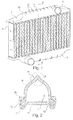
- the in Fig. 1 shown heat exchanger is a coolant radiator (KMK) for a motor vehicle, in this case a commercial vehicle with a diesel engine.
- the KMK has a network of coolant flowed through flat tubes 1 with interposed cooling fins 2, wherein the flat tubes 1 each end in passages 3 of soils 4 of the KMK.
- the flat tubes 1, ribs 2 and bottoms 4 are each made of metal based on aluminum and have been soldered together as a mechanically pre-assembled or cassetted unit in a brazing furnace.
- a box 5 is placed in each case fluid-tight to complete a collector.
- the boxes 5 are made of plastic, for example a glass fiber reinforced polyamide, and each have a connection 6 for the supply or discharge of coolant.
- the existing aluminum floors 4 have edge-side, extending in a longitudinal direction of the floors or in the stacking direction of the flat tubes structures for connection to the boxes 5, which are formed as a bead-like receptacles 7 (see Fig. 2 ).
- the bead-shaped receptacles 7 have upstanding edges 7a, in the upper region of which corrugated slot flanges 7b are formed.
- a respective longitudinal end edge 8 of the fixed box 4 at the bottom 4 is shaped so that it projects into the receptacle 7 and overlapped by the Wellschlitz-flanging and is held in a form-fitting manner.
- a seal 9 is provided, via which a fluid-tight connection of box 5 and Boiden 4 is made. Due to the shape of the corrugated slot flange For example, a latching of the box 5 in the receptacle 7 when inserting the box done. As an alternative or in addition, a reshaping of the edge 7a or of the receptacle 7 for fixing the end edge 8 of the box 5 can also take place.
- a roof area 10 which has a ridge 11 in its upper part.
- the ridge 11 is characterized by the fact that the roof area does not run like a half-round as in the case of known designs, but its flanks ascending from the terminal edges 8 strike each other at a defined angle.
- the roof area 10 has a substantially constant wall thickness of the thickness s, wherein the ridge has a height HD and a width BD.
- the roof area in cross-section also changes in the transition to the ridge its curvature direction, so that there is a turning point.
- a region of concave curvature thus follows in the transition to the ridge 11, which has a minimal radius of curvature R.
- the walls of the box 5 each ascending symmetrically with respect to one another from the terminal edges, then meet at a defined angle, which is between 45 ° and 135 °, in the present case approximately 90 °.
- reinforcing ribs 13 extending transversely to the longitudinal direction are provided in the roof area 10, at least in the region of the ridge 11.
- the reinforcing ribs 13 have a maximum height HR and in the present case run exclusively on the outside of the box 5.
- the ribs 13 but also in addition or exclusively on the inside of the box 5 run.
- the roof area 10 or the ridge 11 can be purposefully reinforced so that the elasticity or rigidity is in the desired range even with a small wall thickness s of the box 5.
- the box walls can yield elastically when the pressure in the collector 4, 5 increases so that the roof area and in particular the ridge widens.
Landscapes
- Engineering & Computer Science (AREA)
- Physics & Mathematics (AREA)
- Thermal Sciences (AREA)
- Mechanical Engineering (AREA)
- General Engineering & Computer Science (AREA)
- Heat-Exchange Devices With Radiators And Conduit Assemblies (AREA)
- Body Structure For Vehicles (AREA)
Abstract
Description
Die Erfindung betrifft einen Wärmetauscher nach dem Oberbegriff des Anspruchs 1.The invention relates to a heat exchanger according to the preamble of claim 1.
Besonders im Bereich der Kühlmittelkühler (KMK) von Kraftfahrzeugen, insbesondere bei Nutzfahrzeugen, werden zunehmende Anforderungen an die Druckfestigkeit gestellt. Gründe hierfür sind etwa eine Anordnung eines Thermostatventils ausgangsseitig des KMK oder auch der Einsatz eines Wasser-Retarders. Dabel können im KMK Drücke von über 4 bar auftreten, wobei herkommliche KMK oft nur für Drücke bis zu 2 bar ausgelegt sind.Particularly in the field of coolant coolers (CMC) of motor vehicles, especially in commercial vehicles, increasing demands are placed on the compressive strength. Reasons for this are, for example, an arrangement of a thermostatic valve on the output side of the KMK or the use of a water retarder. Dabels can experience pressures of over 4 bar in the KMK, whereas conventional KMK are often designed only for pressures up to 2 bar.
Es ist die Aufgabe der Erfindung, einen Wärmetauscher anzugeben, der mit einfachen Mitteln eine besonders hohe Druckfestigkeit aufweist.It is the object of the invention to provide a heat exchanger which has a particularly high compressive strength with simple means.
Diese Aufgabe wird für einen eingangs genannten Wärmetauscher erfindungsgemäß mit den kennzeichnenden Merkmalen des Anspruchs 1 gelöst. Durch die Ausformung des Dachbereichs mit einem First kann dieser bei einer Druckerhöhung elastisch ausweichen, ohne dass die Spannungsgrenzen an der Stelle des Firstes überschritten werden. Hierdurch wird bei gegebenen Materialstärken die resultierende Spannung bzw. Verformung in kritischen Bereichen wie etwa einem Übergang zwischen Boden und Tauscherrohren oder der Verbindung zwischen Kasten und Boden gering gehalten.This object is achieved according to the invention for a heat exchanger mentioned above with the characterizing features of claim 1. Due to the shape of the roof area with a ridge, it can elastically yield when the pressure increases, without exceeding the stress limits at the location of the ridge. As a result, with given material thicknesses, the resulting stress or deformation in critical areas such as a transition between the bottom and exchanger tubes or the connection between the box and the floor is kept low.
Bei einer bevorzugten Ausführungsform der Erfindung besteht der Kasten im Wesentlichen aus einem Kunststoff, wobei ein Dichtmaterial zwischen Kasten und Boden angeordnet ist. Dies ermöglicht eine einfache Bauweise und insbesondere eine kostengünstige Fertigung des Kastens.In a preferred embodiment of the invention, the box consists essentially of a plastic, wherein a sealing material between the box and the bottom is arranged. This allows a simple construction and in particular a cost-effective production of the box.
Allgemein vorteilhaft ist die Struktur zur Verbindung mit dem Kasten als sickenförmige Aufnahme für eine längsseitige Abschlusskante des Kastens ausgeformt. In bevorzugter Detailgestaltung ist dabei an der Aufnahme eine formschlüssige Verbindung mit dem Kasten vorgesehen, besonders bevorzugt mittels einer Wellschlitz-Bördelung. Insgesamt ist hierdurch eine einfache Montage und sichere Halterung des Kastens an dem Boden ermöglicht. Anstelle einer Wellschlitz-Bördelung kann auch eine andere geeignete Maßnahme zur formschlüssigen Festlegung vorgesehen sein, wie zum Beispiel eine Umbiegung vorragender Laschen oder Kanten des Bodens nach dem Einsatzen der Abschlusskante des Kastens in die sickenförmigen Aufnahme.Generally advantageously, the structure for connection to the box is formed as a bead-shaped receptacle for a longitudinal end edge of the box. In a preferred detail design, a form-fitting connection with the box is provided on the receptacle, particularly preferably by means of a corrugated slot flanging. Overall, this allows easy mounting and secure mounting of the box on the ground. Instead of a corrugated flute curling, another suitable measure for the positive fixing can be provided, such as a bend of protruding tabs or edges of the floor after the use of the terminal edge of the box in the bead-shaped receptacle.
Der Boden besteht in vorteilhafter Detailgestaltung aus einem Metall auf Aluminiumbasis, wobei die Tauscherrohre als in den Durchzügen verlöte Flachrohre ausgebildet sind. Dazu werden meist Böden und Hachrohre mechanisch zu einem Tauscherblock kassettiert und gemeinsam zur Verlötung in einen Löteten verbrachtThe bottom consists in an advantageous detailed design of a metal based on aluminum, wherein the exchanger tubes are formed as in the passages soldered flat tubes. These are usually soils and Hachrohre mechanically cassetted into a Tauscherblock and spent together for soldering in a soldering
Bei einer optimierten Ausführungsform der Erfindung hat eine Querschnittslinie des Kastens im Bereich des Firstes eine Wendestelle, wodurch eine umfassende gewünschte Deformation bei erhöhtem Druck verbessert ist.In an optimized embodiment of the invention has a cross-sectional line of the box in the region of the ridge has a turning point, whereby a comprehensive desired deformation at elevated pressure is improved.
In weiterhin optimierter Gestaltung hat der First des Dachbereichs einen Öffnungswinkel zwischen etwa 45° und etwa 135°.In a further optimized design, the ridge of the roof area has an opening angle between about 45 ° and about 135 °.
Bei einem besonders bevorzugten Ausführungsbeispiel sind an dem Kasten im Bereich des Firstes Versteifungsrippen ausgebildet. Hierdurch kann die Wandstärke des Kastens insbesondere in dem Dachbereich kostengünstig und gewichtsmindernd gering gehalten werden, wobei die elastischen Eigenschaften dennoch ausreichend stelf sind, um auch größere Druckerhöhungen aufzufangen.In a particularly preferred embodiment, stiffening ribs are formed on the box in the region of the ridge. As a result, the wall thickness of the box, especially in the roof area can be kept low and weight-reducing low, the elastic properties are still stel enough to absorb even larger pressure increases.
Weitere Vorteile und Merkmale der Erfindung ergeben sich aus den nachfolgend beschriebenen Ausführungsbeispielen sowie aus den abhängigen Ansprüchen.Further advantages and features of the invention will become apparent from the embodiments described below and from the dependent claims.
Nachfolgend werden mehrere Ausführungsbeispiele der Erfindung beschrieben und anhand der anliegenden Zeichnungen näher erläutert.
- Fig. 1
- zeigt eine räumliche Darstellung eines erfindungsgemäßen Wär- metauschers.
- Fig. 2
- zeigt eine Schnittansicht des Wärmetauschers aus
Fig. 1 entlang der Linie A-A - Fig. 3
- zeigt eine Ausschnittsvergrößerung des Bereichs B aus
Fig. 2 . - Fig. 4
- zeigt einen
Fig. 3 entsprechenden Ausschnitt auf Höhe einer Verstärkungsrippe.
- Fig. 1
- shows a spatial representation of a heat exchanger according to the invention.
- Fig. 2
- shows a sectional view of the heat exchanger
Fig. 1 along the line AA - Fig. 3
- shows a partial enlargement of the area B from
Fig. 2 , - Fig. 4
- shows one
Fig. 3 corresponding cutout at the height of a reinforcing rib.
Der in
Die Flachrohre 1, Rippen 2 und Böden 4 bestehen jeweils aus Metall auf Basis von Aluminium und sind als mechanisch vormontierte bzw. kassettierte Einheit in einem Lötofen stoffschlüssig miteinander verlötet worden.The flat tubes 1,
Auf die Böden 4 ist jeweils ein Kasten 5 zur Vervollständigung eines Sammlers fluiddicht aufgesetzt. Die Kästen 5 bestehen aus Kunststoff, zum Beispiel einem glasfaserverstärkten Polyamid, und haben jeweils einen Anschluss 6 zur Zuführung bzw. Abführung von Kühlmittel.On the
Die aus Aluminium bestehenden Böden 4 haben randseitige, sich in einer Längsrichtung der Böden bzw. in Stapelrichtung der Flachrohre erstreckende Strukturen zur Verbindung mit den Kästen 5 auf, die als sickenartige Aufnahmen 7 ausgebildet sind (siehe
Zwischen Abschlusskante 8 und sickenförmiger Aufnahme 7 ist eine Dichtung 9 vorgesehen, über die eine fluiddichte Verbindung von Kasten 5 und Boiden 4 hergestellt ist. Durch die Ausformung der Wellschlitz-Bördelung kann zum Beispiel eine Verrastung des Kastens 5 in der Aufnahme 7 bei Einsetzen des Kastens erfolgen. Es kann alternativ oder ergänzend auch eine Umformung des Randes 7a bzw, der Aufnahme 7 zur Festlegung der Abschlusskante 8 des Kastens 5 erfolgen.Between final edge 8 and bead-shaped receptacle 7, a seal 9 is provided, via which a fluid-tight connection of
Zwischen den Abschlusskanten 8 des Kastens 5 befindet sich über einen Großteil seiner Länge (siehe
Gemäß der Detaildarstellung nach
Im vorliegenden Beispiel ändert der Dachbereich im Querschnitt zudem im Übergang zum First seine Krümmungsrichtung, so dass eine Wendestelle vorliegt. Nach der zunächst von der Abschlusskante ausgehenden konvexen Krümmung folgt im Übergang zum First 11 somit ein Bereich konkaver Krümmung, der einen minimalen Krümmungsradius R aufweist. In der Spitze des Firstes und treffen sich die von den Abschlusskanten jeweils symmetrisch zueinander aufsteigenden Wände des Kastens 5 dann unter einem definierten Winkel, der zwischen 45° und 135° beträgt, vorliegend etwa 90°.In the present example, the roof area in cross-section also changes in the transition to the ridge its curvature direction, so that there is a turning point. After the convex curvature, which initially starts from the terminal edge, a region of concave curvature thus follows in the transition to the
Wie insbesondere
Durch die Verstärkungsrippen 13 kann der Dachbereich 10 bzw. der First 11 gezielt so verstärkt werden, dass die Elastizität bzw. Steifigkeit auch bei geringer Wandstärke s des Kastens 5 im gewünschten Bereich liegt.By means of the reinforcing
Durch die vorstehend beschriebene Formgebung des Kastens mit Dachbereich 10 und First 11 können die Kastenwände bei einer Druckerhöhung im Sammler 4, 5 elastisch so ausweichen, dass der Dachbereich und insbesondere der First sich aufweitet. Hierdurch werden die unteren Wandbereiche, insbesondere in der Nähe der Abschlusskanten 8, steifer gegen eine Deformation.As a result of the above-described shaping of the box with
Dies führt zudem zu einer Versteifung von Übergangsbereichen 12 des Bodens 4 zwischen den Aufnahmen 7 und den Durchzügen 3. Hierdurch wird die Verlötung der Flachrohre 1 mit den Durchzügen 3 im Bereich ihrer kurzen Stirnseiten bei einer Druckerhöhung weniger belastet.This also leads to a stiffening of
Claims (8)
einen Sammler (4, 5) mit einem sich in einer Längsrichtung erstreckenden Boden (4) mit einer Mehrzahl von Durchzügen (3) zur Aufnahme von Tauscherrohren (1), und
einen fluiddicht an dem Boden (4) festlegbaren Kasten (5) des Sammlers (4, 5),
wobei der Boden (4) zumindest eine randseitige, sich in der Längsrichtung erstreckende Struktur (7) zur Verbindung mit dem Kasten (5, 8) aufweist,
dadurch gekennzeichnet,
dass der Kasten (5) zumindest einen in der Längsrichtung erstreckten Dachbereich (10) mit einem First (11) umfasst, wobei eine Druckerhöhung in dem Sammler (4, 5) eine elastische Deformation des Dachbereichs (10, 11) bewirkt.Heat exchanger comprising
a collector (4, 5) having a longitudinally extending bottom (4) with a plurality of passages (3) for receiving exchanger tubes (1), and
a box (5) of the collector (4, 5) which can be fixed in a fluid-tight manner to the bottom (4),
the bottom (4) having at least one edge-side, longitudinally extending structure (7) for connection to the box (5, 8),
characterized,
in that the box (5) comprises at least one longitudinally extended roof area (10) with a ridge (11), wherein a pressure increase in the collector (4, 5) causes an elastic deformation of the roof area (10, 11).
Applications Claiming Priority (1)
| Application Number | Priority Date | Filing Date | Title |
|---|---|---|---|
| DE200920012453 DE202009012453U1 (en) | 2009-09-16 | 2009-09-16 | Collector for a heat exchanger |
Publications (2)
| Publication Number | Publication Date |
|---|---|
| EP2299232A2 true EP2299232A2 (en) | 2011-03-23 |
| EP2299232A3 EP2299232A3 (en) | 2013-12-04 |
Family
ID=41720239
Family Applications (1)
| Application Number | Title | Priority Date | Filing Date |
|---|---|---|---|
| EP10176832.3A Withdrawn EP2299232A3 (en) | 2009-09-16 | 2010-09-15 | Header for a heat exchanger |
Country Status (2)
| Country | Link |
|---|---|
| EP (1) | EP2299232A3 (en) |
| DE (1) | DE202009012453U1 (en) |
Cited By (1)
| Publication number | Priority date | Publication date | Assignee | Title |
|---|---|---|---|---|
| DE102011080204A1 (en) | 2011-08-01 | 2013-02-07 | Behr Gmbh & Co. Kg | Collecting box for heat exchanger such as intercooler used in motor vehicle e.g. motor car, has box wall that is provided with stiffening ribs which are aligned parallel to spread side of bottom portion at which box casing is closed |
Families Citing this family (2)
| Publication number | Priority date | Publication date | Assignee | Title |
|---|---|---|---|---|
| DE102013006956B4 (en) * | 2013-04-23 | 2020-06-04 | Mann+Hummel Gmbh | Air-conducting component with an intercooler |
| US20260078967A1 (en) * | 2024-09-16 | 2026-03-19 | Rtx Corporation | Ruffled heat exchanger fairing |
Family Cites Families (5)
| Publication number | Priority date | Publication date | Assignee | Title |
|---|---|---|---|---|
| DE4129573C2 (en) * | 1991-09-06 | 1997-10-23 | Behr Gmbh & Co | Heat exchanger |
| US6082446A (en) * | 1998-04-20 | 2000-07-04 | Ahaus Tool And Engineering, Inc. | Sealing method and apparatus for a heat exchanger |
| DE19926052B4 (en) * | 1999-06-08 | 2005-09-15 | Daimlerchrysler Ag | heat exchanger unit |
| DE102004033784A1 (en) | 2004-07-12 | 2006-02-02 | Behr Gmbh & Co. Kg | Heat exchangers, in particular intercoolers |
| CN101226029A (en) * | 2008-01-30 | 2008-07-23 | 无锡优萌汽车部件制造有限公司 | Automobile warm-air |
-
2009
- 2009-09-16 DE DE200920012453 patent/DE202009012453U1/en not_active Expired - Lifetime
-
2010
- 2010-09-15 EP EP10176832.3A patent/EP2299232A3/en not_active Withdrawn
Cited By (1)
| Publication number | Priority date | Publication date | Assignee | Title |
|---|---|---|---|---|
| DE102011080204A1 (en) | 2011-08-01 | 2013-02-07 | Behr Gmbh & Co. Kg | Collecting box for heat exchanger such as intercooler used in motor vehicle e.g. motor car, has box wall that is provided with stiffening ribs which are aligned parallel to spread side of bottom portion at which box casing is closed |
Also Published As
| Publication number | Publication date |
|---|---|
| EP2299232A3 (en) | 2013-12-04 |
| DE202009012453U1 (en) | 2010-02-25 |
Similar Documents
| Publication | Publication Date | Title |
|---|---|---|
| EP1616143B1 (en) | Heat exchanger, especially a charge-air cooler for motor vehicles | |
| EP2021717B1 (en) | Heat exchanger for motor vehicles | |
| EP2151655B1 (en) | Heat exchanger and use and production method of a heat exchanger | |
| DE10343239B4 (en) | Heat exchanger | |
| EP2031338A2 (en) | Heat exchanger | |
| DE102011080204A1 (en) | Collecting box for heat exchanger such as intercooler used in motor vehicle e.g. motor car, has box wall that is provided with stiffening ribs which are aligned parallel to spread side of bottom portion at which box casing is closed | |
| DE102008033594A1 (en) | Base e.g. for heat exchanger, has several throughholes with edge and reference plane of base is provided and in sealing contact with base | |
| EP1671073A1 (en) | Charge-air cooler for motor vehicles | |
| DE102011075071A1 (en) | Heat exchangers, in particular intercoolers | |
| EP1842023A1 (en) | Heat exchanger, in particular a charge intercooler or coolant cooler for motor vehicles | |
| EP2029953A1 (en) | Heat exchanger, in particular an intercooler, comprising a reinforced pipe base | |
| EP2299232A2 (en) | Header for a heat exchanger | |
| EP1711771B1 (en) | Heat exchanger | |
| EP1737694A1 (en) | Heat exchanger for a motor vehicle, and method for the production thereof | |
| EP1912035B1 (en) | Motor vehicle cooler | |
| DE19702440A1 (en) | Fuel cooler for diesel engine | |
| EP1890102A1 (en) | Domed header plate for the tank of a heat exchanger | |
| DE102008027842A1 (en) | Collector box for heat exchangers used in vehicles has connecting section with welding surface on opposite side to connection and is produced by extrusion | |
| DE10132485B4 (en) | Collecting box for a heat exchanger | |
| DE102006017610B4 (en) | Heat exchanger for charge air cooling for motor vehicles, system | |
| DE102018113339A1 (en) | Battery cooling device for cooling a battery, in particular the battery of a motor vehicle or arrangement structure with at least one battery, in particular a battery of a motor vehicle and with the aforementioned battery cooling device | |
| EP1853868A1 (en) | Chamber for holding a fluid for a heat exchanger, heat exchanger, more particularly for a heat exchange unit, and a heat exchange unit, in particular in the form of a monoblock | |
| DE102007006235A1 (en) | Heat-exchanger e.g. refrigerant cooler, for motor vehicle, has tube base that is insertable into extended edge area of cover and solderable with cover, where tube base includes set circulating edge | |
| DE102009010039B4 (en) | heat exchangers | |
| DE102008035020A1 (en) | Heat exchanger, particularly radiator for motor vehicle, comprises block, which is formed from pipe elements and fin elements, where block is provided with base element at upper side and lower side |
Legal Events
| Date | Code | Title | Description |
|---|---|---|---|
| PUAI | Public reference made under article 153(3) epc to a published international application that has entered the european phase |
Free format text: ORIGINAL CODE: 0009012 |
|
| AK | Designated contracting states |
Kind code of ref document: A2 Designated state(s): AL AT BE BG CH CY CZ DE DK EE ES FI FR GB GR HR HU IE IS IT LI LT LU LV MC MK MT NL NO PL PT RO SE SI SK SM TR |
|
| AX | Request for extension of the european patent |
Extension state: BA ME RS |
|
| PUAL | Search report despatched |
Free format text: ORIGINAL CODE: 0009013 |
|
| AK | Designated contracting states |
Kind code of ref document: A3 Designated state(s): AL AT BE BG CH CY CZ DE DK EE ES FI FR GB GR HR HU IE IS IT LI LT LU LV MC MK MT NL NO PL PT RO SE SI SK SM TR |
|
| AX | Request for extension of the european patent |
Extension state: BA ME RS |
|
| RIC1 | Information provided on ipc code assigned before grant |
Ipc: F28F 21/08 20060101ALI20131031BHEP Ipc: F28F 9/02 20060101AFI20131031BHEP Ipc: F28F 21/06 20060101ALI20131031BHEP |
|
| STAA | Information on the status of an ep patent application or granted ep patent |
Free format text: STATUS: THE APPLICATION IS DEEMED TO BE WITHDRAWN |
|
| 18D | Application deemed to be withdrawn |
Effective date: 20140605 |