EP2299232A2 - Collecteur pour un échangeur thermique - Google Patents
Collecteur pour un échangeur thermique Download PDFInfo
- Publication number
- EP2299232A2 EP2299232A2 EP10176832A EP10176832A EP2299232A2 EP 2299232 A2 EP2299232 A2 EP 2299232A2 EP 10176832 A EP10176832 A EP 10176832A EP 10176832 A EP10176832 A EP 10176832A EP 2299232 A2 EP2299232 A2 EP 2299232A2
- Authority
- EP
- European Patent Office
- Prior art keywords
- box
- heat exchanger
- ridge
- exchanger according
- collector
- Prior art date
- Legal status (The legal status is an assumption and is not a legal conclusion. Google has not performed a legal analysis and makes no representation as to the accuracy of the status listed.)
- Withdrawn
Links
Images

Classifications
-
- F—MECHANICAL ENGINEERING; LIGHTING; HEATING; WEAPONS; BLASTING
- F28—HEAT EXCHANGE IN GENERAL
- F28F—DETAILS OF HEAT-EXCHANGE AND HEAT-TRANSFER APPARATUS, OF GENERAL APPLICATION
- F28F9/00—Casings; Header boxes; Auxiliary supports for elements; Auxiliary members within casings
- F28F9/02—Header boxes; End plates
- F28F9/0219—Arrangements for sealing end plates into casing or header box; Header box sub-elements
- F28F9/0224—Header boxes formed by sealing end plates into covers
- F28F9/0226—Header boxes formed by sealing end plates into covers with resilient gaskets
-
- F—MECHANICAL ENGINEERING; LIGHTING; HEATING; WEAPONS; BLASTING
- F28—HEAT EXCHANGE IN GENERAL
- F28F—DETAILS OF HEAT-EXCHANGE AND HEAT-TRANSFER APPARATUS, OF GENERAL APPLICATION
- F28F21/00—Constructions of heat-exchange apparatus characterised by the selection of particular materials
- F28F21/06—Constructions of heat-exchange apparatus characterised by the selection of particular materials of plastics material
- F28F21/067—Details
-
- F—MECHANICAL ENGINEERING; LIGHTING; HEATING; WEAPONS; BLASTING
- F28—HEAT EXCHANGE IN GENERAL
- F28F—DETAILS OF HEAT-EXCHANGE AND HEAT-TRANSFER APPARATUS, OF GENERAL APPLICATION
- F28F21/00—Constructions of heat-exchange apparatus characterised by the selection of particular materials
- F28F21/08—Constructions of heat-exchange apparatus characterised by the selection of particular materials of metal
- F28F21/081—Heat exchange elements made from metals or metal alloys
- F28F21/084—Heat exchange elements made from metals or metal alloys from aluminium or aluminium alloys
-
- F—MECHANICAL ENGINEERING; LIGHTING; HEATING; WEAPONS; BLASTING
- F28—HEAT EXCHANGE IN GENERAL
- F28F—DETAILS OF HEAT-EXCHANGE AND HEAT-TRANSFER APPARATUS, OF GENERAL APPLICATION
- F28F2225/00—Reinforcing means
- F28F2225/08—Reinforcing means for header boxes
Definitions
- the invention relates to a heat exchanger according to the preamble of claim 1.
- WO 2006/005449 describes a charge air cooler for a motor vehicle, in which a plastic box is fixed fluid-tight at lateral receiving beads of a bottom made of aluminum by means of a seal.
- the box has a semicircular or semicircular cross-sectional profile.
- the box consists essentially of a plastic, wherein a sealing material between the box and the bottom is arranged. This allows a simple construction and in particular a cost-effective production of the box.
- the structure for connection to the box is formed as a bead-shaped receptacle for a longitudinal end edge of the box.
- a form-fitting connection with the box is provided on the receptacle, particularly preferably by means of a corrugated slot flanging.
- a corrugated slot flanging is provided on the receptacle, particularly preferably by means of a corrugated slot flanging.
- this allows easy mounting and secure mounting of the box on the ground.
- another suitable measure for the positive fixing can be provided, such as a bend of protruding tabs or edges of the floor after the use of the terminal edge of the box in the bead-shaped receptacle.
- the bottom consists in an advantageous detailed design of a metal based on aluminum, wherein the exchanger tubes are formed as in the passages soldered flat tubes. These are usually soils and Hachrohre mechanically cassetted into a Tauscherblock and spent together for soldering in a soldering
- the ridge of the roof area has an opening angle between about 45 ° and about 135 °.
- stiffening ribs are formed on the box in the region of the ridge.
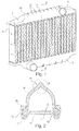
- the in Fig. 1 shown heat exchanger is a coolant radiator (KMK) for a motor vehicle, in this case a commercial vehicle with a diesel engine.
- the KMK has a network of coolant flowed through flat tubes 1 with interposed cooling fins 2, wherein the flat tubes 1 each end in passages 3 of soils 4 of the KMK.
- the flat tubes 1, ribs 2 and bottoms 4 are each made of metal based on aluminum and have been soldered together as a mechanically pre-assembled or cassetted unit in a brazing furnace.
- a box 5 is placed in each case fluid-tight to complete a collector.
- the boxes 5 are made of plastic, for example a glass fiber reinforced polyamide, and each have a connection 6 for the supply or discharge of coolant.
- the existing aluminum floors 4 have edge-side, extending in a longitudinal direction of the floors or in the stacking direction of the flat tubes structures for connection to the boxes 5, which are formed as a bead-like receptacles 7 (see Fig. 2 ).
- the bead-shaped receptacles 7 have upstanding edges 7a, in the upper region of which corrugated slot flanges 7b are formed.
- a respective longitudinal end edge 8 of the fixed box 4 at the bottom 4 is shaped so that it projects into the receptacle 7 and overlapped by the Wellschlitz-flanging and is held in a form-fitting manner.
- a seal 9 is provided, via which a fluid-tight connection of box 5 and Boiden 4 is made. Due to the shape of the corrugated slot flange For example, a latching of the box 5 in the receptacle 7 when inserting the box done. As an alternative or in addition, a reshaping of the edge 7a or of the receptacle 7 for fixing the end edge 8 of the box 5 can also take place.
- a roof area 10 which has a ridge 11 in its upper part.
- the ridge 11 is characterized by the fact that the roof area does not run like a half-round as in the case of known designs, but its flanks ascending from the terminal edges 8 strike each other at a defined angle.
- the roof area 10 has a substantially constant wall thickness of the thickness s, wherein the ridge has a height HD and a width BD.
- the roof area in cross-section also changes in the transition to the ridge its curvature direction, so that there is a turning point.
- a region of concave curvature thus follows in the transition to the ridge 11, which has a minimal radius of curvature R.
- the walls of the box 5 each ascending symmetrically with respect to one another from the terminal edges, then meet at a defined angle, which is between 45 ° and 135 °, in the present case approximately 90 °.
- reinforcing ribs 13 extending transversely to the longitudinal direction are provided in the roof area 10, at least in the region of the ridge 11.
- the reinforcing ribs 13 have a maximum height HR and in the present case run exclusively on the outside of the box 5.
- the ribs 13 but also in addition or exclusively on the inside of the box 5 run.
- the roof area 10 or the ridge 11 can be purposefully reinforced so that the elasticity or rigidity is in the desired range even with a small wall thickness s of the box 5.
- the box walls can yield elastically when the pressure in the collector 4, 5 increases so that the roof area and in particular the ridge widens.
Landscapes
- Engineering & Computer Science (AREA)
- Physics & Mathematics (AREA)
- Thermal Sciences (AREA)
- Mechanical Engineering (AREA)
- General Engineering & Computer Science (AREA)
- Heat-Exchange Devices With Radiators And Conduit Assemblies (AREA)
- Body Structure For Vehicles (AREA)
Applications Claiming Priority (1)
| Application Number | Priority Date | Filing Date | Title |
|---|---|---|---|
| DE200920012453 DE202009012453U1 (de) | 2009-09-16 | 2009-09-16 | Sammler für einen Wärmetauscher |
Publications (2)
| Publication Number | Publication Date |
|---|---|
| EP2299232A2 true EP2299232A2 (fr) | 2011-03-23 |
| EP2299232A3 EP2299232A3 (fr) | 2013-12-04 |
Family
ID=41720239
Family Applications (1)
| Application Number | Title | Priority Date | Filing Date |
|---|---|---|---|
| EP10176832.3A Withdrawn EP2299232A3 (fr) | 2009-09-16 | 2010-09-15 | Collecteur pour un échangeur thermique |
Country Status (2)
| Country | Link |
|---|---|
| EP (1) | EP2299232A3 (fr) |
| DE (1) | DE202009012453U1 (fr) |
Cited By (1)
| Publication number | Priority date | Publication date | Assignee | Title |
|---|---|---|---|---|
| DE102011080204A1 (de) | 2011-08-01 | 2013-02-07 | Behr Gmbh & Co. Kg | Sammelkasten für einen Wärmetauscher, insbesondere einen Ladeluftkühler |
Families Citing this family (2)
| Publication number | Priority date | Publication date | Assignee | Title |
|---|---|---|---|---|
| DE102013006956B4 (de) * | 2013-04-23 | 2020-06-04 | Mann+Hummel Gmbh | Luftführendes Bauteil mit einem Ladeluftkühler |
| US20260078967A1 (en) * | 2024-09-16 | 2026-03-19 | Rtx Corporation | Ruffled heat exchanger fairing |
Family Cites Families (5)
| Publication number | Priority date | Publication date | Assignee | Title |
|---|---|---|---|---|
| DE4129573C2 (de) * | 1991-09-06 | 1997-10-23 | Behr Gmbh & Co | Wärmetauscher |
| US6082446A (en) * | 1998-04-20 | 2000-07-04 | Ahaus Tool And Engineering, Inc. | Sealing method and apparatus for a heat exchanger |
| DE19926052B4 (de) * | 1999-06-08 | 2005-09-15 | Daimlerchrysler Ag | Wärmetauschereinheit |
| DE102004033784A1 (de) | 2004-07-12 | 2006-02-02 | Behr Gmbh & Co. Kg | Wärmetauscher, insbesondere Ladeluftkühler |
| CN101226029A (zh) * | 2008-01-30 | 2008-07-23 | 无锡优萌汽车部件制造有限公司 | 汽车暖风 |
-
2009
- 2009-09-16 DE DE200920012453 patent/DE202009012453U1/de not_active Expired - Lifetime
-
2010
- 2010-09-15 EP EP10176832.3A patent/EP2299232A3/fr not_active Withdrawn
Cited By (1)
| Publication number | Priority date | Publication date | Assignee | Title |
|---|---|---|---|---|
| DE102011080204A1 (de) | 2011-08-01 | 2013-02-07 | Behr Gmbh & Co. Kg | Sammelkasten für einen Wärmetauscher, insbesondere einen Ladeluftkühler |
Also Published As
| Publication number | Publication date |
|---|---|
| DE202009012453U1 (de) | 2010-02-25 |
| EP2299232A3 (fr) | 2013-12-04 |
Similar Documents
| Publication | Publication Date | Title |
|---|---|---|
| EP1616143B1 (fr) | Echangeur thermique, en particulier refroidisseur d'air de suralimentation pour vehicules automobiles | |
| EP2021717B1 (fr) | Échangeur thermique pour vehicules automobiles | |
| DE10343239B4 (de) | Wärmeübertrager | |
| EP1769210B1 (fr) | Echangeur thermique, en particulier refroidisseur d'air de suralimentation | |
| EP1707911A1 (fr) | Échangeur de chaleur, par exemple refroidisseur d'air de suralimentation et procédé de fabrication | |
| DE102008033594A1 (de) | Boden für einen Wärmetauscher | |
| DE102011080204A1 (de) | Sammelkasten für einen Wärmetauscher, insbesondere einen Ladeluftkühler | |
| EP1842023B1 (fr) | Echangeur de chaleur, en particulier refroidisseur d'air de suralimentation ou refroidisseur de milieu de refroidissement pour des vehicules a moteur | |
| EP1671073A1 (fr) | Refroidisseur d'air de suralimentation pour véhicules | |
| DE102011075071A1 (de) | Wärmetauscher, insbesondere Ladeluftkühler | |
| EP2029953A1 (fr) | Échangeur thermique, notamment refroidisseur d'air de suralimentation, à fond tubulaire renforcé | |
| DE102017214822A1 (de) | Wärmeübertrager | |
| EP1711771B1 (fr) | Echangeur de chaleur | |
| EP1737694A1 (fr) | Echangeur thermique pour vehicule automobile, et son procede de production | |
| DE202009012453U1 (de) | Sammler für einen Wärmetauscher | |
| EP1890102B1 (fr) | Plaque tubulaire voûtée pour un bac collecteur d'un échangeur thermique | |
| EP1912035B1 (fr) | Refroidisseur de véhicule automobile | |
| DE102008027842A1 (de) | Sammelkasten eines Wärmeträgers | |
| DE10132485B4 (de) | Sammelkasten für einen Wärmetauscher | |
| DE102006017610B4 (de) | Wärmetauscher zur Ladeluftkühlung für Kraftfahrzeuge, System | |
| DE102004049670B4 (de) | Kraftstoffkühler, Kraftfahrzeug mit einem derartigen Kraftstoffkühler | |
| EP1853868A1 (fr) | Caisse concue pour recevoir un fluide pour un echangeur thermique, echangeur thermique, en particulier pour une unite d'echangeur thermique, unite d'echangeur thermique, en particulier concue sous forme de monobloc | |
| DE102007006235A1 (de) | Wärmeübertrager in Ganzaluminiumbauweise, insbesondere für Kraftfahrzeuge | |
| DE102009010039B4 (de) | Wärmetauscher | |
| DE102008035020A1 (de) | Wärmeübertrager |
Legal Events
| Date | Code | Title | Description |
|---|---|---|---|
| PUAI | Public reference made under article 153(3) epc to a published international application that has entered the european phase |
Free format text: ORIGINAL CODE: 0009012 |
|
| AK | Designated contracting states |
Kind code of ref document: A2 Designated state(s): AL AT BE BG CH CY CZ DE DK EE ES FI FR GB GR HR HU IE IS IT LI LT LU LV MC MK MT NL NO PL PT RO SE SI SK SM TR |
|
| AX | Request for extension of the european patent |
Extension state: BA ME RS |
|
| PUAL | Search report despatched |
Free format text: ORIGINAL CODE: 0009013 |
|
| AK | Designated contracting states |
Kind code of ref document: A3 Designated state(s): AL AT BE BG CH CY CZ DE DK EE ES FI FR GB GR HR HU IE IS IT LI LT LU LV MC MK MT NL NO PL PT RO SE SI SK SM TR |
|
| AX | Request for extension of the european patent |
Extension state: BA ME RS |
|
| RIC1 | Information provided on ipc code assigned before grant |
Ipc: F28F 21/08 20060101ALI20131031BHEP Ipc: F28F 9/02 20060101AFI20131031BHEP Ipc: F28F 21/06 20060101ALI20131031BHEP |
|
| STAA | Information on the status of an ep patent application or granted ep patent |
Free format text: STATUS: THE APPLICATION IS DEEMED TO BE WITHDRAWN |
|
| 18D | Application deemed to be withdrawn |
Effective date: 20140605 |