EP2299346A1 - Systeme, Verfahren und Vorrichtungen zur Überwachung und Steuerung einer windbetriebenen Maschine - Google Patents
Systeme, Verfahren und Vorrichtungen zur Überwachung und Steuerung einer windbetriebenen Maschine Download PDFInfo
- Publication number
- EP2299346A1 EP2299346A1 EP10175692A EP10175692A EP2299346A1 EP 2299346 A1 EP2299346 A1 EP 2299346A1 EP 10175692 A EP10175692 A EP 10175692A EP 10175692 A EP10175692 A EP 10175692A EP 2299346 A1 EP2299346 A1 EP 2299346A1
- Authority
- EP
- European Patent Office
- Prior art keywords
- component
- driven machine
- wind driven
- operating
- data
- Prior art date
- Legal status (The legal status is an assumption and is not a legal conclusion. Google has not performed a legal analysis and makes no representation as to the accuracy of the status listed.)
- Withdrawn
Links
Images

Classifications
-
- G—PHYSICS
- G05—CONTROLLING; REGULATING
- G05B—CONTROL OR REGULATING SYSTEMS IN GENERAL; FUNCTIONAL ELEMENTS OF SUCH SYSTEMS; MONITORING OR TESTING ARRANGEMENTS FOR SUCH SYSTEMS OR ELEMENTS
- G05B23/00—Testing or monitoring of control systems or parts thereof
- G05B23/02—Electric testing or monitoring
- G05B23/0205—Electric testing or monitoring by means of a monitoring system capable of detecting and responding to faults
- G05B23/0259—Electric testing or monitoring by means of a monitoring system capable of detecting and responding to faults characterized by the response to fault detection
- G05B23/0286—Modifications to the monitored process, e.g. stopping operation or adapting control
- G05B23/0291—Switching into safety or degraded mode, e.g. protection and supervision after failure
-
- F—MECHANICAL ENGINEERING; LIGHTING; HEATING; WEAPONS; BLASTING
- F03—MACHINES OR ENGINES FOR LIQUIDS; WIND, SPRING, OR WEIGHT MOTORS; PRODUCING MECHANICAL POWER OR A REACTIVE PROPULSIVE THRUST, NOT OTHERWISE PROVIDED FOR
- F03D—WIND MOTORS
- F03D17/00—Monitoring or testing of wind motors, e.g. diagnostics
-
- F—MECHANICAL ENGINEERING; LIGHTING; HEATING; WEAPONS; BLASTING
- F03—MACHINES OR ENGINES FOR LIQUIDS; WIND, SPRING, OR WEIGHT MOTORS; PRODUCING MECHANICAL POWER OR A REACTIVE PROPULSIVE THRUST, NOT OTHERWISE PROVIDED FOR
- F03D—WIND MOTORS
- F03D7/00—Controlling wind motors
- F03D7/02—Controlling wind motors the wind motors having rotation axis substantially parallel to the air flow entering the rotor
- F03D7/0204—Controlling wind motors the wind motors having rotation axis substantially parallel to the air flow entering the rotor for orientation in relation to wind direction
-
- F—MECHANICAL ENGINEERING; LIGHTING; HEATING; WEAPONS; BLASTING
- F03—MACHINES OR ENGINES FOR LIQUIDS; WIND, SPRING, OR WEIGHT MOTORS; PRODUCING MECHANICAL POWER OR A REACTIVE PROPULSIVE THRUST, NOT OTHERWISE PROVIDED FOR
- F03D—WIND MOTORS
- F03D7/00—Controlling wind motors
- F03D7/02—Controlling wind motors the wind motors having rotation axis substantially parallel to the air flow entering the rotor
- F03D7/022—Adjusting aerodynamic properties of the blades
- F03D7/0224—Adjusting blade pitch
-
- Y—GENERAL TAGGING OF NEW TECHNOLOGICAL DEVELOPMENTS; GENERAL TAGGING OF CROSS-SECTIONAL TECHNOLOGIES SPANNING OVER SEVERAL SECTIONS OF THE IPC; TECHNICAL SUBJECTS COVERED BY FORMER USPC CROSS-REFERENCE ART COLLECTIONS [XRACs] AND DIGESTS
- Y02—TECHNOLOGIES OR APPLICATIONS FOR MITIGATION OR ADAPTATION AGAINST CLIMATE CHANGE
- Y02E—REDUCTION OF GREENHOUSE GAS [GHG] EMISSIONS, RELATED TO ENERGY GENERATION, TRANSMISSION OR DISTRIBUTION
- Y02E10/00—Energy generation through renewable energy sources
- Y02E10/70—Wind energy
- Y02E10/72—Wind turbines with rotation axis in wind direction
Definitions
- the invention relates to wind driven machines, and more specifically, to systems, methods, and apparatus for monitoring and controlling a wind driven machine.
- Wind driven machines such as wind mills, wind driven generators, and wind wheel type machines can be adapted to provide useful work and/or for energy conversion.
- Wind turbines for example, are a type of wind driven machine that can be used for energy conversion and to provide a source of alternative energy.
- a wind turbine can include a housing or nacelle positioned atop a truss or a tubular tower.
- a rotor having multiple blades that are aerodynamically designed to transform wind energy into a form of mechanical energy.
- the multiple blades positioned about a rotor can transform the kinetic energy of the wind into rotational motion of the rotor, a form of mechanical energy.
- the rotational motion of the rotor can be used to drive a mechanical load or be further converted into electrical energy using one or more generators.
- wind driven machines like wind turbines can include one or more components for adapting certain characteristics of the turbine to ambient conditions, thereby improving the wind driven machine's efficiency.
- a wind turbine can include components associated with yaw control for turning the rotor and blades into the direction of the wind. Additional components can be included for pitch control to turn the blades and to increase or decrease the aerodynamic load. Other components associated with turbine control and modification can also be provided. Because these components are associated with wind turbine efficiency, their reliable and continuous operation is generally desired. Conventional wind turbines, however, have only limited safeguards for ensuring these components are functioning properly. When one or more of these components begin operating in an alert condition, which could indicate the component is malfunctioning, the efficiency of the wind turbine suffers. In some instances, when one or more of these components malfunctions, the wind turbine may require deactivation, resulting in power disruption and economic loss.
- a method for monitoring and controlling a wind driven machine can be provided.
- the method can include operating a component in a wind driven machine at an operating condition.
- the method can also include determining whether an alert condition associated with the component in the wind driven machine exists based on an electrical characteristic associated with the component.
- the method can further include outputting an indicator when an alert condition associated with the component in the wind driven machine exists.
- a system for monitoring and controlling a wind driven machine can be provided.
- the system can include a wind driven machine having a component and a data collection module for collecting operating data from the component.
- the system can also include a data processing module for receiving the operating data, for determining whether the operating data indicates the component is operating in an alert condition, and for providing an indicator when the component is operating in an alert condition.
- the operating data can comprise an electrical characteristic associated with the component.
- an apparatus for monitoring and controlling a wind driven machine can be provided.
- the apparatus can include data collection module for collecting operating data from a component in a wind driven machine.
- the apparatus can also include a data processing module for receiving the operating data, for determining whether the operating data indicates the component is operating in an alert condition, and for providing an indicator when the component is operating in an alert condition.
- FIG. 1 illustrates an exemplary system 100 according to one embodiment of the invention.
- System 100 can include any wind driven machine such as a wind mill, a wind driven generator, a wind wheel type machine, or a wind turbine like wind turbine 105, which is illustrated as part of exemplary system 100.
- Wind turbine 105 can comprise a nacelle 110 mounted atop a truss or tower 115.
- Wind turbine 105 also comprises a rotor 120 that includes a plurality of rotor blades 125 mounted to a rotating hub 130.
- the wind turbine 105 illustrated in FIG. 1 can include two rotor blades 125.
- nacelle 110 can house a number of components, such as a generator for generating electrical power and/or one or more components associated with turbine operation and performance, such as control system 135.
- Control system 135 can comprise one or more microcontrollers operable for overall system monitoring and control including pitch and speed regulation, shaft and yaw brake application, and fault monitoring to name a few.
- control system 135 is illustrated as being part of a central control architecture within wind turbine 105. In other embodiments, distributed and/or remotely located control architectures can be used.
- control system 135 can be associated with system monitoring and control to improve, maintain, or modify wind turbine 105 performance, such as by interfacing with one or more components.
- One such component can be pitch drive 140, which can comprise a DC pitch drive motor for controlling the pitch of blades 125.
- the pitch of blades 125 can be associated with harnessing the kinetic energy of the wind and for driving rotating hub 130.
- control system 135 is shown as providing control to pitch drive 140, in other embodiments, the pitches of blades 125 can be controlled by individual controllers or other control mechanisms and modules rather than, or in combination with, a control architecture like control system 135.
- Yaw drive 145 can provide yaw orientation for wind turbine 105.
- yaw drive 145 can be operated and/or controlled by control system 135, such as through one or more sensors for measuring flange displacement and/or through wind vane 146.
- yaw drive 145 can be operated by individual controllers or other control mechanisms and modules rather than, or in combination with, a control architecture like control system 135.
- Yaw orientation for wind turbine 105 can correspond to the position of rotor 120 in relation to wind direction. It is generally desirable to orient rotor 120 facing the direction of the wind, thereby reducing the angle of incidence between blades 125 and the wind's kinetic energy. Once a desired position is reached, wind turbine 105 can be maintained in this position or further adapted as variations in wind direction require.
- Components such as pitch drive 140 and yaw drive 145 can be useful for wind turbine 105 operation. In conventional systems, however, no monitoring or control is provided to such components. Because components like pitch drive 140 and yaw drive 145 can malfunction, without any monitoring or control, conventional systems can suffer lasting damage or even require shut down when such malfunction occurs. For instance, when components like yaw drive 145 falter or fail, damage can result to the associated pinions and gears. This damage can not be easily detected or repaired without manual inspection, which often does not occur for a lengthy period of time. At other times, the severity of the damage can trigger the wind turbine's deactivation, resulting in shutdown and power loss.
- System 100 can generally avoid these lasting effects and can reduce power losses associated with component malfunction that could result in system deactivation.
- System 100 can provide continuous and/or selective monitoring of one or more components of a wind driven machine like pitch drive 140 and yaw drive 145. When abnormal operation is detected, system 100 can modify the performance of wind turbine 105, or other wind driven machine, to prevent or reduce lasting damage and/or power loss. For example, system 100 can generate a warning or fault message via warning system 150 for indicating an alert condition and/or for requesting manual inspection.
- system 100 can modify wind turbine 105 performance by isolating a malfunctioning component and redirecting control of wind turbine 105 to other components based on ambient conditions and/or other wind turbine parameters as shown at 155.
- wind turbine 105 can include multiple yaw drives 145 so that should one yaw drive 145 malfunction, power to the malfunctioning yaw drive 145 can be interrupted or a brake utilized.
- a brake can be utilized to halt operation of the malfunctioning yaw drive 145.
- a brake can be disabled to allow the malfunctioning yaw drive 145 to operate freely and to reduce the likelihood of further damage.
- control of the remaining yaw drives 145 can be modified to compensate for the malfunctioning yaw drive 145.
- wind turbine 105 can be derated to account for ambient conditions and/or other wind turbine parameters 155. In these embodiments, while power produced from wind turbine 105 is reduced, power is not lost and relatively less damage to wind turbine 105 can result from the malfunctioning yaw drive 145 due to the reduced load.
- System 100 can include data collection module 160.
- Data collection module 160 can be operable to collect operating data associated with one or more components in a wind driven machine like wind turbine 105.
- data collection module 160 can include one or more sensors for providing information associated with one or more components of wind turbine 105.
- data collection module 160 can comprise current measurement sensors coupled to a power supply and to one or more components in wind turbine 105, such as pitch drive 140 and/or yaw drive 145.
- current measurement sensors can be coupled to data collection module 160.
- Current measurement sensors can measure the electrical current delivered to one or more components in wind turbine 105, such as pitch drive 140 and/or yaw drive 145.
- Data collection module 160 can be adapted to measure and/or record the abnormal electrical load and to provide abnormal electrical load information to data processing module 165.
- system 100 can include filter 170 for conditioning the operating data provided by data collection module 160 to data processing module 165.
- the data collection module 160 and data processing module 165 can be referred to as an apparatus but may be embodied as individual or distinct components.
- filter 170 can reduce distortions and/or disruptions in the operation of system 100 that can result from temporary fluctuations in certain parameters, conditions, and/or measurements.
- filter 170 can be coupled to data collection module 160 and data processing module 165.
- filter 170 can be coupled to one or more sensors and data collection module 160.
- filter 170 can be integrated into data collection module 160 and/or data processing module 165.
- Data processing module 165 can be operable to receive operating data from data collection module 160 and to determine whether a component alert condition exists based partly on the operating data provided.
- a component alert condition can correspond to the operating condition of one or more components.
- a component alert condition can correspond to a malfunctioning component, such as a component that is operating abnormally, is faltering, or is failing.
- a component alert condition can correspond to a properly functioning component and/or a component operating within a normal operating range.
- a component alert condition can correspond to any or all of the above.
- Data processing module 165 can comprise various controllers, modules, and/or memory structures for receiving data, storing data, and comparing data. According to the illustrated embodiment, after receiving operating data from data collection module 160 associated with one or more components such as pitch drive 140 and/or yaw drive 145, data processing module 165 can compare the received operating data with at least one reference condition or operating data comprising at least one reference condition to determine whether an alert condition exists.
- operating data for a reference condition can be statistically determined and based on historical operational data.
- operating data for a reference condition can comprise an average value and can include zero or more standard deviations for a component in the wind turbine according to the component's functional characteristics over a period of time.
- operating data for a reference condition can be predefined, such as through measurements taken during one or more test conditions.
- operating data for a reference condition can include a threshold value, and still in other embodiments, operating data for a reference condition can be based at least in part on industry standards, legal regulations, or design constraints.
- an alert condition can be evidenced by the difference between an expected reference value and the real time value provided by data collection module 160. Should an alert condition exist, data processing module 165 can output an indicator as described further below.
- System 100 can be adapted to continuously monitor and control a wind driven machine like wind turbine 105 or to selectively monitor and control a wind driven machine like wind turbine 105. That is, an operating condition for determining whether an alert condition exists can be either a continuous operating condition or a selected operating condition, such as an operational test. In one embodiment, system 100 can be adapted for continuous monitoring, and the operating condition can be defined according to an ambient condition associated with the wind driven machine or other parameter as shown at 155. Based on wind turbine parameters 155, such as an ambient condition associated with the wind turbine 105 comprising one or more of a wind speed, a pitch angle, or a power output of wind turbine 105, system 100 can determine whether one or more alert conditions exists.
- wind turbine parameters 155 such as an ambient condition associated with the wind turbine 105 comprising one or more of a wind speed, a pitch angle, or a power output of wind turbine 105, system 100 can determine whether one or more alert conditions exists.
- data processing module 165 can store operational data for a plurality of wind turbine parameters. As wind turbine parameters 155 are provided to data processing module 165, the operating data for the reference condition defined by the wind turbine parameters 155 can be retrieved by data processing module 165 and compared to the operating data provided by the data collection module 160. In other embodiments, data processing module 165 can estimate the operating data for the reference condition using wind turbine parameters 155 and can compare the expected operating data to operating data provided by the data collection module 160.
- system 100 can be adapted to selectively monitor and control a wind driven machine like wind turbine 105 during one or more sampling periods.
- Sampling periods can be based on one or more specified conditions. For instance, low wind speed may provide a good opportunity for selectively monitoring a wind driven machine like wind turbine 105 given the lower demands and loads associated with lower wind speeds.
- Particular pitch angles or power outputs for wind turbine 105 may also provide good opportunities as can certain operational tests.
- Operational tests can include any functional test associated with wind turbine 105, such as a cable twist release test, a yaw operational test, or a pitch battery test, all of which can be performed at various wind speeds and with or without power being produced by wind turbine 105.
- system 100 can selectively monitor a wind driven machine like wind turbine 105 through data collection module 160 and data processing module 165 by recording current levels associated with one or more components, such as pitch drive 140 and/or yaw drive 145, and by comparing recorded values to one or more reference values. It will be appreciated that as system 100 can selectively monitor wind turbine 105 during specified sampling periods, system 100 can also selectively monitor wind turbine 105 during multiple sampling periods. For instance, according to one aspect of the invention, sampling periods can be combined to form a multi-sampling period with corresponding multi-reference criteria. Selectively monitoring wind turbine 105 over multiple sampling periods may improve failure detections by correlating component operational features across dissimilar reference periods. As an example, if an abnormal current load for yaw drive component 145 is detected during one sampling period A, the yaw drive component 145 component can be selectively monitored during another sampling period B to further evaluate whether an alert condition may exist.
- data processing module 165 can output an indicator of the alert condition.
- an indicator can correspond to triggering an alarm and/or a fault message in warning system 150 for indicating a malfunctioning component, for requesting maintenance, or for assisting inspection.
- Such an indicator can also correspond to one or more command signals provided to wind turbine 105 and/or the one or more malfunctioning components.
- the indicator can correspond to a command signal provided to control system 135 for derating a wind driven machine like wind turbine 105, such as when one of a plurality of yaw drives 145 malfunctions. If one yaw drive 145 malfunctions, the data processing module 165 can provide a command signal to control system 135 identifying the malfunctioning yaw drive 145. Control system 135 can compensate for the malfunctioning yaw drive 145 by adapting the remaining yaw drives 145 accordingly. Such compensation can be based on the power production load of wind turbine 105 and/or on ambient conditions associated with wind turbine 105 like wind speed, pitch angle, and turbulence measures.
- the remaining yaw drives 145 can operate under a limited load condition without suffering lasting damage. Should additional yaw drives 145 malfunction, then control system 135 can further derate the wind driven machine and can even deactivate the wind driven machine to avoid lasting damage, such as when a plurality of yaw drives 145 malfunction.
- indicators provided by data processing module 165 can be associated with a malfunctioning component.
- yaw drive 145 can comprise two control components: one a circuit breaker linked to a power supply; the other a brake for releasing or stopping the drive.
- power to a malfunctioning yaw drive 145 can be interrupted through activation of the circuit breaker, or the malfunctioning yaw drive 145 can be stopped or released through utilization of the brake.
- the malfunctioning yaw drive 145 can be isolated when an alert condition exists, and damage associated with the malfunctioning yaw drive 145 can be reduced.
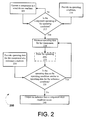
- FIG. 2 illustrates an exemplary method 200 for monitoring and controlling a wind driven machine.
- Method 200 can begin at block 205 where a component in a wind driven machine, such as wind turbine 105, can be operated.
- the component can be any component in a wind driven machine, such as pitch drive 140 or yaw drive 145.
- more than one component in a wind driven machine can be operated at block 205, such as a plurality of pitch drives 140, a plurality of yaw drives 145, or a plurality combination of each.
- an operating condition can be provided.
- An operating condition can be either a continuous operating condition or a selective operating condition.
- the operating condition can be provided according to one or more ambient conditions associated with the wind driven machine, such as a wind speed, a pitch angle, or a power output of the wind driven machine.
- the operating condition at block 210 can also be part of an operational test associated with the wind driven machine.
- An operational test can include any functional test associated with the wind driven machine, such as a cable twist release test, a yaw operational test, or a pitch battery test.
- operating data for the one or more components can be measured.
- Operating data for the wind driven machine can be related to an electrical characteristic of the component in the wind driven machine, such as a current, voltage, impedance, or power characteristic.
- an electrical sensor can be used to measure the operating data for the wind driven machine.
- an electrical sensor in combination with or as a part of another module, such as data collection module 160 in system 100, can be used to measure operating data for the component in the wind driven machine.
- Block 225 can filter the operating data measured for the one or more components. Filtering the operating data for the one or more components at block 225 can condition the operating data and can reduce distortions and/or disruptions that may exist in the operating data, such as from temporary fluctuations in certain parameters, conditions, and/or measurements. It will be appreciated that while block 225 is illustrated in method 200 as being implemented after operating data for the one or more components in the wind turbine is measured, block 225 can also be implemented before operating data is measured in block 220 or as a part of block 220.
- operating data for the one or more components in the wind driven machine at a reference condition can be provided.
- Operating data for a reference condition can be associated with a mathematical determination, an estimate, be based on historical data, or be previously defined.
- operating data for a reference condition can be statistically determined and based on historical operational data for one or more components over a period of time or over one or more operational parameters.
- operating data for a reference condition can be based on one or more measurements recorded during one or more test conditions.
- operating data for a reference condition can be determined according to industry standards, legal regulations, or design constraints. In other embodiments, any combination of the above methods for providing operating data for a reference condition can be provided.
- Method 200 can continue at block 235 and can determine whether the operating data for the one or more components is similar to the operating data for the one or more components at the reference condition. For example, in one embodiment, the operating data for the one or more components can be compared to operating data for the one or more components at a reference condition. When comparing the operating data, an alert condition may be evidenced by the difference between a reference value and a real time value as measured from the one or more components at the operating condition.
- method 200 can proceed to block 240 where an indicator of the one or more component alert conditions can be provided.
- An indicator can be associated with a warning signal, a wind driven machine command signal, or a component command signal.
- a warning or fault message can be provided at block 240 such as via warning system 150 in system 100.
- a warning or fault message can indicate a component alert condition and/or can request manual inspection of the wind driven machine and/or component.
- the wind driven machine can be derated according to one or more command signals provided to the wind driven machine at block 240.
- the failed component can be isolated according to one or more command signals provided to the component at block 240.
- One or more command signals for isolating the one or more malfunctioning components can include, for example, command signals for utilizing a brake or interrupting power to the malfunctioning component.
- any combination of the above indicators can be provided at block 240.
- Outputting an indicator at block 240 can identify a need for timely or untimely maintenance for the wind driven machine and can thus reduce unnecessary damage associated with wind driven machine operation when there is a malfunctioning component.
- outputting an indicator at block 240 for isolating the one or more malfunctioning components and/or modifying the wind driven machine's operation to account for the malfunctioning component can likewise reduce unnecessary damage. Consequently, various embodiments of the invention can reduce the risk of damage associated with lengthy maintenance intervals, and by isolating or indicating the one or more malfunctioning components, certain embodiments of the invention can enable better maintenance practices. Reduced damage and better maintenance practices are at least some technical effects of certain aspects of the invention. Furthermore, because malfunctioning components can be isolated and/or indicated and the wind turbine modified for continued operation, various embodiments of the invention can avoid power disruptions associated with malfunctioning components in a wind driven machine. More reliable power production from a wind driven machine is at least one other technical effect.
- At least one data processing module operable to:
Landscapes
- Engineering & Computer Science (AREA)
- Mechanical Engineering (AREA)
- Life Sciences & Earth Sciences (AREA)
- Sustainable Development (AREA)
- Sustainable Energy (AREA)
- Chemical & Material Sciences (AREA)
- Combustion & Propulsion (AREA)
- General Engineering & Computer Science (AREA)
- Physics & Mathematics (AREA)
- General Physics & Mathematics (AREA)
- Automation & Control Theory (AREA)
- Fluid Mechanics (AREA)
- Wind Motors (AREA)
Applications Claiming Priority (1)
| Application Number | Priority Date | Filing Date | Title |
|---|---|---|---|
| US12/562,525 US8279073B2 (en) | 2009-09-18 | 2009-09-18 | Systems, methods, and apparatus for monitoring and controlling a wind driven machine |
Publications (1)
| Publication Number | Publication Date |
|---|---|
| EP2299346A1 true EP2299346A1 (de) | 2011-03-23 |
Family
ID=42223548
Family Applications (1)
| Application Number | Title | Priority Date | Filing Date |
|---|---|---|---|
| EP10175692A Withdrawn EP2299346A1 (de) | 2009-09-18 | 2010-09-08 | Systeme, Verfahren und Vorrichtungen zur Überwachung und Steuerung einer windbetriebenen Maschine |
Country Status (3)
| Country | Link |
|---|---|
| US (1) | US8279073B2 (de) |
| EP (1) | EP2299346A1 (de) |
| CN (1) | CN102022266B (de) |
Cited By (8)
| Publication number | Priority date | Publication date | Assignee | Title |
|---|---|---|---|---|
| CN102411367A (zh) * | 2011-11-16 | 2012-04-11 | 许继集团有限公司 | 大型风力发电机组主控测试系统及方法 |
| EP2535570B1 (de) | 2011-06-16 | 2016-06-08 | Availon GmbH | Windnachführungsanordnung einer Windenergieanlage. |
| EP3144529A1 (de) * | 2015-09-15 | 2017-03-22 | Jörn GmbH | Windenergieanlage mit wenigstens einem elastisch verformbaren bauteil und verfahren zur feststellung des beginns einer verschleissbedingten bauteil-restnutzungsdauer in einer windenergieanlage |
| CN107448363A (zh) * | 2015-10-27 | 2017-12-08 | 南通大学 | 具备数据异常实时监测的多微处理器垂直轴风力发电测试装置 |
| CN107664099A (zh) * | 2015-10-27 | 2018-02-06 | 南通大学 | 含动态健康程度判别的无线通讯式垂直轴风力发电监测装置 |
| CN107676224A (zh) * | 2017-09-28 | 2018-02-09 | 新疆金风科技股份有限公司 | 用于风力发电机组的偏航系统 |
| WO2024133288A1 (de) * | 2022-12-20 | 2024-06-27 | Fraunhofer-Gesellschaft zur Förderung der angewandten Forschung e.V. | Anordnung und verfahren zur überwachung eines elektrisch angetriebenen systems und system, insbesondere windenergieanlage, mit einer solchen anordnung |
| EP4542025A1 (de) * | 2023-10-19 | 2025-04-23 | Nordex Energy Spain, S.A.U. | Verfahren zum betreiben einer windenergieanlage und windenergieanlage |
Families Citing this family (18)
| Publication number | Priority date | Publication date | Assignee | Title |
|---|---|---|---|---|
| US8584530B2 (en) * | 2009-08-19 | 2013-11-19 | Avl Test Systems, Inc. | Wind turbine gearbox testing system |
| US9869298B2 (en) | 2010-06-29 | 2018-01-16 | Vestas Wind Systems A/S | Rotational positioning system in a wind turbine |
| CN102644545B (zh) * | 2011-02-18 | 2013-07-31 | 华锐风电科技(集团)股份有限公司 | 风电机组故障处理方法及系统 |
| JP6228914B2 (ja) * | 2011-05-06 | 2017-11-08 | コンドル ウインド エナジー リミテッド | ヨーイングによって動力出力を制御する2枚羽根付き揺動ヒンジ風力タービンにおいて動力出力を制御するために必要とされるヨートルクを最小にするためのシステム |
| DK2636893T3 (en) * | 2012-03-07 | 2016-11-28 | Siemens Ag | A method for controlling the operation of a wind turbine |
| EP2754886B1 (de) * | 2013-01-14 | 2016-01-06 | ALSTOM Renewable Technologies | Verfahren zum Betreiben eines Windturbinenrotationssystems sowie Windturbinenrotationssystem |
| JP6476089B2 (ja) * | 2015-07-28 | 2019-02-27 | 株式会社日立製作所 | 風力発電システム |
| KR101685850B1 (ko) * | 2015-11-12 | 2016-12-20 | 두산중공업 주식회사 | 풍력 발전기 유닛의 제어 장치 및 이를 이용한 제어 방법 |
| ES2902603T3 (es) * | 2016-02-16 | 2022-03-29 | Vestas Wind Sys As | Sistema de control para una turbina eólica que comprende un controlador de pala para cada pala de la turbina eólica |
| CN105909479B (zh) * | 2016-06-30 | 2018-11-27 | 华北电力科学研究院有限责任公司 | 应用于风力发电机组偏航控制性能测试的数据采集装置 |
| EP3559455B1 (de) * | 2016-12-22 | 2022-02-02 | Vestas Wind Systems A/S | Messumformerströme in einem windturbinengenerator |
| EP3559453B1 (de) * | 2016-12-22 | 2021-11-17 | Vestas Wind Systems A/S | Windturbinengeneratorsteuergerät und verfahren |
| CN109723609B (zh) * | 2017-10-31 | 2021-03-02 | 中国电力科学研究院有限公司 | 一种风电机组变桨系统的故障预警方法及系统 |
| EP3740670B1 (de) * | 2018-01-18 | 2024-07-31 | ABB Schweiz AG | Verfahren, vorrichtung und system zur windumrichterverwaltung |
| WO2020125897A1 (en) | 2018-12-20 | 2020-06-25 | Vestas Wind Systems A/S | Method and apparatus for monitoring the condition of a yaw system |
| CN110388304B (zh) * | 2019-07-10 | 2020-12-08 | 许昌许继风电科技有限公司 | 一种偏航驱动器自动测试系统 |
| EP4085308A1 (de) * | 2019-12-31 | 2022-11-09 | General Electric Company | System und verfahren zum detektieren von anomalien in windturbinensteuersignalen |
| EP4542031A1 (de) * | 2023-10-19 | 2025-04-23 | Nordex Energy Spain, S.A.U. | Verfahren zum betreiben einer windenergieanlage und windenergieanlage |
Citations (4)
| Publication number | Priority date | Publication date | Assignee | Title |
|---|---|---|---|---|
| US20060070435A1 (en) * | 2003-02-03 | 2006-04-06 | Lemieux David L | Method and apparatus for condition-based monitoring of wind turbine components |
| EP1903213A2 (de) * | 2006-09-20 | 2008-03-26 | Hitachi, Ltd. | Windkraftanlage und Verfahren zur Steuerung des Rotoreinstellwinkels |
| WO2009003478A2 (en) * | 2007-06-29 | 2009-01-08 | Vestas Wind Systems A/S | Thermal monitoring of doubly-fed generator |
| WO2009042581A1 (en) * | 2007-09-24 | 2009-04-02 | Edsa Micro Corporation | Real-time stability indexing for intelligent energy monitoring and management of electrical power network system |
Family Cites Families (12)
| Publication number | Priority date | Publication date | Assignee | Title |
|---|---|---|---|---|
| EP0094561A3 (de) | 1982-05-06 | 1984-09-12 | Egon Schick | Handvorrichtung für die Handhabung von Reisszwecken, Reissnägeln, Heftzwecken od. dgl. Nägeln |
| DE3406321A1 (de) | 1984-02-22 | 1985-08-22 | Basf Ag, 6700 Ludwigshafen | Bindemittel fuer korrosionsschutzanstriche auf basis von poly(meth)acrylat-latices und wasserloeslichen polymeren zinkkomplexsalzen |
| BR8405016A (pt) | 1984-10-04 | 1986-05-13 | Charles Helle | Processo para a preparacao de polvoras propelentes |
| EP0186519A2 (de) | 1984-12-27 | 1986-07-02 | Epid Inc. | Einschreiben von Information in eine Anzeigevorrichtung |
| CN100390426C (zh) | 2002-04-24 | 2008-05-28 | 威斯塔斯风力系统公开有限公司 | 风力涡轮机、液压系统、抽气系统及控制至少两台风力涡轮机叶片的方法 |
| AU2003264087A1 (en) | 2003-08-21 | 2005-03-10 | General Electric Company | Wind turbine blade pitch change by means of electric stepping motor |
| CA2557396C (en) * | 2004-02-27 | 2010-12-21 | Mitsubishi Heavy Industries, Ltd. | Wind turbine generator, active damping method thereof, and windmill tower |
| CN101238287B (zh) | 2005-07-08 | 2011-05-11 | 维斯塔斯风力系统有限公司 | 风轮机、风轮机用的轮毂及其使用 |
| US7642748B2 (en) * | 2005-10-19 | 2010-01-05 | General Electric Company | Battery charging system and method of operating same |
| US8480367B2 (en) | 2006-11-03 | 2013-07-09 | Vestas Wind Systems A/S | Yawing system for a wind turbine |
| US8028604B2 (en) * | 2007-01-26 | 2011-10-04 | General Electric Company | Methods and systems for turning rotary components within rotary machines |
| US8128361B2 (en) * | 2008-12-19 | 2012-03-06 | Frontier Wind, Llc | Control modes for extendable rotor blades |
-
2009
- 2009-09-18 US US12/562,525 patent/US8279073B2/en not_active Expired - Fee Related
-
2010
- 2010-09-08 EP EP10175692A patent/EP2299346A1/de not_active Withdrawn
- 2010-09-17 CN CN201010294576.5A patent/CN102022266B/zh not_active Expired - Fee Related
Patent Citations (4)
| Publication number | Priority date | Publication date | Assignee | Title |
|---|---|---|---|---|
| US20060070435A1 (en) * | 2003-02-03 | 2006-04-06 | Lemieux David L | Method and apparatus for condition-based monitoring of wind turbine components |
| EP1903213A2 (de) * | 2006-09-20 | 2008-03-26 | Hitachi, Ltd. | Windkraftanlage und Verfahren zur Steuerung des Rotoreinstellwinkels |
| WO2009003478A2 (en) * | 2007-06-29 | 2009-01-08 | Vestas Wind Systems A/S | Thermal monitoring of doubly-fed generator |
| WO2009042581A1 (en) * | 2007-09-24 | 2009-04-02 | Edsa Micro Corporation | Real-time stability indexing for intelligent energy monitoring and management of electrical power network system |
Non-Patent Citations (1)
| Title |
|---|
| JOHN LEPKOWSKI: "Motor Control Sensor Feedback Circuits", 1 January 2003 (2003-01-01), XP055228387, Retrieved from the Internet <URL:http://ww1.microchip.com/downloads/en/AppNotes/00894a.pdf> [retrieved on 20151113] * |
Cited By (12)
| Publication number | Priority date | Publication date | Assignee | Title |
|---|---|---|---|---|
| EP2535570B1 (de) | 2011-06-16 | 2016-06-08 | Availon GmbH | Windnachführungsanordnung einer Windenergieanlage. |
| CN102411367A (zh) * | 2011-11-16 | 2012-04-11 | 许继集团有限公司 | 大型风力发电机组主控测试系统及方法 |
| CN102411367B (zh) * | 2011-11-16 | 2013-06-19 | 许继集团有限公司 | 大型风力发电机组主控测试系统及方法 |
| EP3144529A1 (de) * | 2015-09-15 | 2017-03-22 | Jörn GmbH | Windenergieanlage mit wenigstens einem elastisch verformbaren bauteil und verfahren zur feststellung des beginns einer verschleissbedingten bauteil-restnutzungsdauer in einer windenergieanlage |
| CN107448363A (zh) * | 2015-10-27 | 2017-12-08 | 南通大学 | 具备数据异常实时监测的多微处理器垂直轴风力发电测试装置 |
| CN107664099A (zh) * | 2015-10-27 | 2018-02-06 | 南通大学 | 含动态健康程度判别的无线通讯式垂直轴风力发电监测装置 |
| CN107664099B (zh) * | 2015-10-27 | 2019-03-05 | 南通大学 | 含动态健康程度判别的无线通讯式垂直轴风力发电监测装置 |
| CN107448363B (zh) * | 2015-10-27 | 2019-03-05 | 南通大学 | 具备数据异常实时监测的多微处理器垂直轴风力发电测试装置 |
| CN107676224A (zh) * | 2017-09-28 | 2018-02-09 | 新疆金风科技股份有限公司 | 用于风力发电机组的偏航系统 |
| WO2024133288A1 (de) * | 2022-12-20 | 2024-06-27 | Fraunhofer-Gesellschaft zur Förderung der angewandten Forschung e.V. | Anordnung und verfahren zur überwachung eines elektrisch angetriebenen systems und system, insbesondere windenergieanlage, mit einer solchen anordnung |
| EP4542025A1 (de) * | 2023-10-19 | 2025-04-23 | Nordex Energy Spain, S.A.U. | Verfahren zum betreiben einer windenergieanlage und windenergieanlage |
| WO2025082687A1 (en) * | 2023-10-19 | 2025-04-24 | Nordex Energy Spain S.A.U. | Method for operating a wind turbine and wind turbine |
Also Published As
| Publication number | Publication date |
|---|---|
| US20100138060A1 (en) | 2010-06-03 |
| US8279073B2 (en) | 2012-10-02 |
| CN102022266B (zh) | 2014-09-17 |
| CN102022266A (zh) | 2011-04-20 |
Similar Documents
| Publication | Publication Date | Title |
|---|---|---|
| US8279073B2 (en) | Systems, methods, and apparatus for monitoring and controlling a wind driven machine | |
| CN102472248B (zh) | 用于避免共因关机的风力发电场控制器 | |
| CN104019000B (zh) | 风力发电机组的载荷谱测定与前瞻性维护系统 | |
| EP2609326B1 (de) | Verfahren zum betrieb einer windturbine und windturbine | |
| CN101839806B (zh) | 风力发电机组及其疲劳载荷监测系统 | |
| US8157523B2 (en) | Method for the operation of a wind energy plant | |
| CN110608134B (zh) | 控制风力涡轮以最大限度减小转子叶片损坏的系统和方法 | |
| EP3543523B1 (de) | System und verfahren zum testen einer energiespeichervorrichtung eines windturbinenneigungswinkelsystems | |
| CN104968931A (zh) | 用于控制风力涡轮机的方法、系统和控制器 | |
| EP3796016B1 (de) | System und verfahren zur erkennung von batteriefehlern in einem anstellsystem einer windturbine | |
| JP6847118B2 (ja) | 風力発電設備 | |
| CN114787505A (zh) | 用于监测风力涡轮的转子叶片健康的系统和方法 | |
| CN114945750A (zh) | 用于控制风力涡轮的系统和方法 | |
| CN201546898U (zh) | 风力发电机组及其状态监测系统 | |
| CN112727678B (zh) | 基于多容错模式的风机变桨控制系统 | |
| EP3722597A1 (de) | System und verfahren zur verhinderung von katastrophalen schäden im antriebsstrang einer windturbine | |
| CN113586359B (zh) | 用于响应于叶片脱落事件而控制风力涡轮的系统和方法 | |
| US12607163B2 (en) | System and method for detecting and responding to rotor blade damage in a wind turbine | |
| KR20160064873A (ko) | 풍력발전기 피치 시스템 및 그 제어 방법 | |
| WO2025077991A1 (en) | System and method for predicting a pitch fault in a wind turbine | |
| WO2026046525A1 (en) | Methods for detecting structural damage of a wind turbine blade and wind turbines | |
| CN118911944A (zh) | 一种风电场风机叶片除冰方法及系统 | |
| CN117267050A (zh) | 一种风力发电机组防飞车控制系统及控制方法 | |
| CN118327888A (zh) | 一种风力发电机超速时应急顺桨安全装置及方法 |
Legal Events
| Date | Code | Title | Description |
|---|---|---|---|
| PUAI | Public reference made under article 153(3) epc to a published international application that has entered the european phase |
Free format text: ORIGINAL CODE: 0009012 |
|
| AK | Designated contracting states |
Kind code of ref document: A1 Designated state(s): AL AT BE BG CH CY CZ DE DK EE ES FI FR GB GR HR HU IE IS IT LI LT LU LV MC MK MT NL NO PL PT RO SE SI SK SM TR |
|
| AX | Request for extension of the european patent |
Extension state: BA ME RS |
|
| 17P | Request for examination filed |
Effective date: 20110923 |
|
| 17Q | First examination report despatched |
Effective date: 20190423 |
|
| STAA | Information on the status of an ep patent application or granted ep patent |
Free format text: STATUS: THE APPLICATION IS DEEMED TO BE WITHDRAWN |
|
| 18D | Application deemed to be withdrawn |
Effective date: 20190823 |