EP2299497A1 - Dispositif de production d'électricité solaire - Google Patents
Dispositif de production d'électricité solaire Download PDFInfo
- Publication number
- EP2299497A1 EP2299497A1 EP08790986A EP08790986A EP2299497A1 EP 2299497 A1 EP2299497 A1 EP 2299497A1 EP 08790986 A EP08790986 A EP 08790986A EP 08790986 A EP08790986 A EP 08790986A EP 2299497 A1 EP2299497 A1 EP 2299497A1
- Authority
- EP
- European Patent Office
- Prior art keywords
- circuit
- solar battery
- solar
- power line
- attenuating
- Prior art date
- Legal status (The legal status is an assumption and is not a legal conclusion. Google has not performed a legal analysis and makes no representation as to the accuracy of the status listed.)
- Withdrawn
Links
Images



Classifications
-
- H—ELECTRICITY
- H10—SEMICONDUCTOR DEVICES; ELECTRIC SOLID-STATE DEVICES NOT OTHERWISE PROVIDED FOR
- H10F—INORGANIC SEMICONDUCTOR DEVICES SENSITIVE TO INFRARED RADIATION, LIGHT, ELECTROMAGNETIC RADIATION OF SHORTER WAVELENGTH OR CORPUSCULAR RADIATION
- H10F77/00—Constructional details of devices covered by this subclass
- H10F77/95—Circuit arrangements
- H10F77/953—Circuit arrangements for devices having potential barriers
- H10F77/955—Circuit arrangements for devices having potential barriers for photovoltaic devices
-
- Y—GENERAL TAGGING OF NEW TECHNOLOGICAL DEVELOPMENTS; GENERAL TAGGING OF CROSS-SECTIONAL TECHNOLOGIES SPANNING OVER SEVERAL SECTIONS OF THE IPC; TECHNICAL SUBJECTS COVERED BY FORMER USPC CROSS-REFERENCE ART COLLECTIONS [XRACs] AND DIGESTS
- Y02—TECHNOLOGIES OR APPLICATIONS FOR MITIGATION OR ADAPTATION AGAINST CLIMATE CHANGE
- Y02E—REDUCTION OF GREENHOUSE GAS [GHG] EMISSIONS, RELATED TO ENERGY GENERATION, TRANSMISSION OR DISTRIBUTION
- Y02E10/00—Energy generation through renewable energy sources
- Y02E10/50—Photovoltaic [PV] energy
Definitions
- Patent Document 3 There is a method of remote-monitoring a relay operation via a communication line, by providing a current detection relay in the middle of a bypass circuit.
- a signal separating unit takes out the signal of the specific frequency, thereby making it possible to determine presence of a failure of a solar battery module or presence of an electromotive-force shortage.
- An attenuating circuit 4 and a bypass diode 5 are provided in each of the bypass circuits 3.
- the attenuating circuit 4 and the bypass diode 5 are connected in series.
- Series circuits of the attenuating circuits 4 and the bypass diodes 5 are connected in parallel to the connection units 2 such that cathodes of the bypass diodes 5 are connected to current flow-out sides of the solar cells 1.
- the attenuating circuits 4 can attenuate amplitudes of transmission signals transmitted from the transmitting circuit 14 to the power line 8.
- a lowpass filter or a bandpass filter can be used for the attenuating circuits 4.
- Direct-current power is also conducted to the bypass circuit 3 also when the amount of solar radiation decreases.
- the solar cell 1 is naturally restored when an amount of solar radiation is restored. Therefore, to prevent an erroneous determination that the solar battery 6 has a failure when the amount of solar radiation decreases, it can be determined such that, when it is determined that direct-current power is continuously conducted to the bypass circuit 3 at the same position for a certain period of time, there is an recoverable failure in any of the solar battery modules 6 of the solar battery strings 7A and 7B.
- FIG. 1 a configuration having only two rows of the solar battery strings 7A and 7B connected in parallel is shown.
- the number of rows of solar battery strings connected in parallel is not limited to two, and can be any number when one or more rows of solar battery strings are connected in parallel.
- the number of the solar cells 1 that form the connection unit 2 is not limited to two, and any number of the solar cell 1 can be provided when at least one solar cell 1 is provided in the connection unit 2.
- FIG. 2 depicts a waveform of a periodic signal when no failure occurs in any of solar cells 1 shown in FIG. 1 .
- a system voltage V is a voltage at both ends of the power line 8 connected to the inverter 12 shown in FIG. 1 .
- the periodic signals 20 and 21 transmitted from the transmitting circuit 14 reach the receiving circuit 15 without passing through any attenuating circuit 4 of the solar battery strings 7A and 7B. Therefore, the receiving circuit 15 detects that amplitudes of the periodic signals 20 and 21 transmitted from the transmitting circuit 14 are substantially ⁇ V1, and determines that attenuation amounts of the periodic signals 20 and 21 are substantially zero. When it is determined that the attenuation amounts of the periodic signals transmitted from the transmitting circuit 14 are substantially zero, the determining circuit 19 can determine that direct-current power is not conducted to the bypass circuit 3, and can determine that there is no unrecoverable failure in any of the solar battery modules 6 of the solar battery strings 7A and 7B.
- FIG. 4 is a block diagram of a configuration example of the transmitting circuit 14 shown in FIG. 1 .
- the transmitting circuit 14 includes a coil 16 arranged to cover the power line 8, a periodic power source 18 that supplies to the coil 16 a current of which an amplitude changes cyclically, and a transmitting switch 17 that turns ON/OFF a current flowing through the coil 16.
- the periodic power source 18 can change a frequency of a current supplied to the coil 16, and can supply currents of the frequencies F1 and F2 to the coil 16, for example.
- the transmitting switch 17 is ON from the time T1 to T2 and from the time T3 to T4 in FIG. 2 .
- the periodic power source 18 can set a frequency of a current at F1 from the time T1 to T2, and can set a frequency of a current at F2 from the time T3 to T4.
- the transmitting circuit 14 and the receiving circuit 15 are provided in the middle of the power line 8, and the attenuating circuit 4 of a simple configuration is provided in the middle of the bypass circuit 3, thereby achieving a detection of a failure in the solar power generation device. Therefore, the arrangement freedom and installability of a failure detecting unit are high. A failure can be detected easily at low cost. A periodic signal can be always securely superimposed on the power line 8, and a conduction operation of direct-current power to the bypass circuit 3 can be stably and securely detected.
- a periodic signal is not limited to a sinusoidal wave signal and can be a triangular wave or a rectangular wave signal.
- a periodic signal can be a half wave signal having an amplitude in upper or lower directions instead of a wave having a uniform amplitude in upper and low directions from a center voltage.
- the transmitting circuit 14 and the receiving circuit 15 can be arranged to be temporarily provided in the power line 8 only at the time of superimposing a periodic signal or receiving a signal.
- the transmitting circuit 14 and the receiving circuit 15 can be arranged to be temporarily provided in the power line 8 only when a test operation is performed to the solar power generation device.
- Frequency bands of periodic signals capable of passing the attenuating circuits 32A and 32B can be differentiated from each other.
- the attenuating circuit 32A can only pass a frequency band of the periodic signal attenuated by the attenuating circuit 4 at a solar battery string 7A side
- the attenuating circuit 32B can only pass a frequency band of the periodic signal attenuated by the attenuating circuit 4 at a solar battery string 7B side.
- the periodic signal 20 input to the solar battery string 7A passes through the solar battery string 7A without passing through the attenuating circuit 4, and is input to the receiving circuit 15 via the power line 8.
- the periodic signal 21 input to the solar battery string 7B passes through the solar battery string 7B without passing through the attenuating circuit 4, and is input to the receiving circuit 15 via the power line 8.
- the determining circuit 19 determines that direct-current power is not conducted to any of the bypass circuits 3 of the solar battery strings 7A and 7B, and determines that there is no unrecoverable failure in any of the solar battery modules 6 of the solar battery strings 7A and 7B.
- the attenuating circuit 4 within the bypass circuit 3 connected in parallel to the connection unit 2 formed by the solar cell 1 is conducted. Therefore, the periodic signal 20 of the frequency F1 passing through the attenuating circuit 32A reaches the receiving circuit 15 via the attenuating circuit 4 within the bypass circuit 3 connected in parallel to the connection unit 2 formed by the solar cell 1 in which the failure occurs.
- the periodic signal 20 of the frequency F1 is attenuated by the attenuating circuit 32B. Therefore, the periodic signal 20 of the frequency F1 reaching the receiving circuit 15 via the power line 8B at the solar battery string 7B side can be substantially disregarded.
- the periodic signal 21 of the frequency F2 is attenuated by the attenuating circuit 32A. Therefore, the periodic signal 21 of the frequency F2 reaching the receiving circuit 15 via the power line 8A at the solar battery string 7A side can be substantially disregarded.
- the receiving circuit 15 detects that an attenuation amount of the periodic signal 21 of the frequency F2 passing through the attenuating circuit 32B exceeds a prescribed value.
- the determining circuit 19 determines that direct-current power is conducted to any of the bypass circuits 3 of the solar battery string 7B, and determines that there is an unrecoverable failure in any of the solar battery modules 6 of the solar battery string 7B.
- the attenuating circuits 32A and 32B can be temporarily conducted by changing over the changeover circuits 34 and 35 to sides of the attenuating circuits 32A and 32B when transmitting the periodic signals 20 and 21 to the solar battery strings 7A and 7B.
- the transmitting circuit 14 and the receiving circuit 15 shown in FIG. 7 when the periodic signals 20 and 21 are transmitted to the attenuating circuits 32A and 32B by providing changeover switches and a bypass power line to bypass the transmitting circuit 14 and the receiving circuit 15 on the power line 8, respectively, the transmitting circuit 14 and the receiving circuit 15 can be temporarily conducted by switching the changeover switches to the sides of the transmitting circuit 14 and the receiving circuit 15.
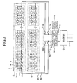
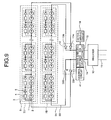
- FIG. 9 is a block diagram of a schematic configuration of a solar power generation device according to a fourth embodiment of the present invention.
- this solar power generation device includes switches 33A and 33B and a control circuit 41 that performs a switch control of the switches 33A and 33B, in addition to the configuration of the solar power generation device shown in FIG. 1 .
- Mechanical switches can be used or electronic switching elements such as transistors can be used for the switches 33A and 33B.
- the switch 33A is connected to the power line 8A at the current flow-in side to the solar battery string 7A
- the switch 33B is connected to the power line 8B at the current flow-in side to the solar battery string 7B.
- the switch 33A can be connected to the power line 8A at the current flow-out side to the solar battery string 7A
- the switch 33B can be connected to the power line 8B at the current flow-out side to the solar battery string 7B.
- a periodic signal transmitted from the transmitting circuit 14 can be arranged to have only a single frequency component, and the attenuating circuits 4 having the same attenuation characteristic can be arranged to be used in the solar battery strings 7A and 7B.
- attenuation characteristics of the attenuating circuits 4 of the solar battery strings 7A and 7B can be set as common such that a periodic signal of the frequency F1 is attenuated by providing the frequency of F1 shown in FIG. 2 in the periodic signal.
- the control circuit 41 closes all the switches 33A and 33B to set the power lines 8A and 8B in a conductive state.
- the control circuit 41 closes only one of the switches 33A and 33B provided on the power lines 8A and 8B, respectively, thereby setting one of the power lines 8A and 8B in a conductive state.
- the control circuit 41 closes the switch 33A and opens the switch 33B.
- the periodic signal 20 having the frequency F1 in FIG. 2 is transmitted from the transmitting circuit 14 to the power line 8
- the periodic signal 20 is input to the solar battery string 7A via the switch 33A.
- the periodic signal 20 input to the solar battery string 7A passes through the solar battery string 7A without passing through the attenuating circuit 4, and is input to the receiving circuit 15 via the power line 8.
- the receiving circuit 15 detects that an attenuation amount of the periodic signal 20 transmitted from the transmitting circuit 14 is substantially zero, the determining circuit 19 determines that direct-current power is not conducted to any of the bypass circuits 3 of the solar battery string 7A, and determines that there is no unrecoverable failure in any of the solar battery modules 6 of the solar battery string 7A.
- the attenuating circuit 4 within the bypass circuit 3 connected in parallel to the connection unit 2 formed by the solar cell 1 is conducted. Therefore, the periodic signal 20 of the frequency F1 transmitted from the transmitting circuit 14 reaches the receiving circuit 15 via the attenuating circuit 4 within the bypass circuit 3 connected in parallel to the connection unit 2 formed by the solar cell 1 in which the failure occurs.
- the receiving circuit 15 detects that an attenuation amount of the periodic signal 20 of the frequency F1 exceeds a prescribed value.
- the determining circuit 19 determines that direct-current power is conducted to any of the bypass circuits 3 of the solar battery string 7A, and determines that there is an unrecoverable failure in any of the solar battery modules 6 of the solar battery string 7A.
- the control circuit 41 opens the switch 33A and closes the switch 33B.
- the periodic signal 20 having the frequency F1 in FIG. 2 is transmitted from the transmitting circuit 14 to the power line 8
- the periodic signal 20 is input to the solar battery string 7B via the switch 33B.
- the periodic signal 20 input to the solar battery string 7B passes through the solar battery string 7B without passing through the attenuating circuit 4, and is input to the receiving circuit 15 via the power line 8.
- the receiving circuit 15 detects that an attenuation amount of the periodic signal 20 transmitted from the transmitting circuit 14 is substantially zero, the determining circuit 19 determines that direct-current power is not conducted to any of the bypass circuits 3 of the solar battery string 7B, and determines that there is no unrecoverable failure in any of the solar battery modules 6 of the solar battery string 7B.
- the receiving circuit 15 detects that an attenuation amount of the periodic signal 20 of the frequency F1 exceeds a prescribed value.
- the determining circuit 19 determines that direct-current power is conducted to any of the bypass circuits 3 of the solar battery string 7B, and determines that there is an unrecoverable failure in any of the solar battery modules 6 of the solar battery string 7B.
- Attenuation characteristics of the attenuating circuits 4 of the solar battery strings 7A and 7B are set such that periodic signals of one kind of the frequency F1 are attenuated after setting the frequency of F1 in the periodic signals.
- attenuation characteristics of the attenuating circuits 4 of the M solar battery modules of each of the solar battery strings 7A and 7B can be set such that the periodic signals of the frequencies F1 to FM are attenuated.
- numbers of the solar cells 1 within the connection unit 2, the connection units 2 within the solar battery module 6, and the solar battery modules 7A and 7B within the solar power generation device are two, these numbers are not limited to two, and can be one, three, or more. Although the number of the solar battery modules 6 within the solar battery strings 7A and 7B is three or more in the above embodiments, the number can be one or two.
- the solar power generation device is suitable for a method of detecting a failure of a solar battery module in which an abnormal solar cell can be bypassed via a bypass circuit.
Landscapes
- Photovoltaic Devices (AREA)
- Charge And Discharge Circuits For Batteries Or The Like (AREA)
- Life Sciences & Earth Sciences (AREA)
- Engineering & Computer Science (AREA)
- Sustainable Development (AREA)
- Sustainable Energy (AREA)
Applications Claiming Priority (1)
| Application Number | Priority Date | Filing Date | Title |
|---|---|---|---|
| PCT/JP2008/062349 WO2010004622A1 (fr) | 2008-07-08 | 2008-07-08 | Dispositif de production d'électricité solaire |
Publications (2)
| Publication Number | Publication Date |
|---|---|
| EP2299497A1 true EP2299497A1 (fr) | 2011-03-23 |
| EP2299497A4 EP2299497A4 (fr) | 2014-02-19 |
Family
ID=41506756
Family Applications (1)
| Application Number | Title | Priority Date | Filing Date |
|---|---|---|---|
| EP08790986.7A Withdrawn EP2299497A4 (fr) | 2008-07-08 | 2008-07-08 | Dispositif de production d'électricité solaire |
Country Status (5)
| Country | Link |
|---|---|
| US (1) | US9184312B2 (fr) |
| EP (1) | EP2299497A4 (fr) |
| JP (1) | JP5073058B2 (fr) |
| CN (1) | CN102089883B (fr) |
| WO (1) | WO2010004622A1 (fr) |
Cited By (3)
| Publication number | Priority date | Publication date | Assignee | Title |
|---|---|---|---|---|
| AT12793U1 (de) * | 2011-05-26 | 2012-11-15 | Austria Tech & System Tech | Photovoltaisches modul und verwendung desselben |
| WO2013037740A3 (fr) * | 2011-09-12 | 2014-04-10 | Sma Solar Technology Ag | Dispositif de sécurité pour système photovoltaïque |
| EP4060895A4 (fr) * | 2020-03-17 | 2023-01-11 | Huawei Digital Power Technologies Co., Ltd. | Système photovoltaïque et procédé de regroupement d'unités photovoltaïques |
Families Citing this family (63)
| Publication number | Priority date | Publication date | Assignee | Title |
|---|---|---|---|---|
| US10693415B2 (en) | 2007-12-05 | 2020-06-23 | Solaredge Technologies Ltd. | Testing of a photovoltaic panel |
| US11881814B2 (en) | 2005-12-05 | 2024-01-23 | Solaredge Technologies Ltd. | Testing of a photovoltaic panel |
| US8384243B2 (en) | 2007-12-04 | 2013-02-26 | Solaredge Technologies Ltd. | Distributed power harvesting systems using DC power sources |
| US8013472B2 (en) | 2006-12-06 | 2011-09-06 | Solaredge, Ltd. | Method for distributed power harvesting using DC power sources |
| US11735910B2 (en) | 2006-12-06 | 2023-08-22 | Solaredge Technologies Ltd. | Distributed power system using direct current power sources |
| US11296650B2 (en) | 2006-12-06 | 2022-04-05 | Solaredge Technologies Ltd. | System and method for protection during inverter shutdown in distributed power installations |
| US9130401B2 (en) | 2006-12-06 | 2015-09-08 | Solaredge Technologies Ltd. | Distributed power harvesting systems using DC power sources |
| US8963369B2 (en) | 2007-12-04 | 2015-02-24 | Solaredge Technologies Ltd. | Distributed power harvesting systems using DC power sources |
| US8473250B2 (en) | 2006-12-06 | 2013-06-25 | Solaredge, Ltd. | Monitoring of distributed power harvesting systems using DC power sources |
| US8319483B2 (en) | 2007-08-06 | 2012-11-27 | Solaredge Technologies Ltd. | Digital average input current control in power converter |
| US11888387B2 (en) | 2006-12-06 | 2024-01-30 | Solaredge Technologies Ltd. | Safety mechanisms, wake up and shutdown methods in distributed power installations |
| US8947194B2 (en) | 2009-05-26 | 2015-02-03 | Solaredge Technologies Ltd. | Theft detection and prevention in a power generation system |
| US11855231B2 (en) | 2006-12-06 | 2023-12-26 | Solaredge Technologies Ltd. | Distributed power harvesting systems using DC power sources |
| US11569659B2 (en) | 2006-12-06 | 2023-01-31 | Solaredge Technologies Ltd. | Distributed power harvesting systems using DC power sources |
| US9112379B2 (en) | 2006-12-06 | 2015-08-18 | Solaredge Technologies Ltd. | Pairing of components in a direct current distributed power generation system |
| US9088178B2 (en) | 2006-12-06 | 2015-07-21 | Solaredge Technologies Ltd | Distributed power harvesting systems using DC power sources |
| US11309832B2 (en) | 2006-12-06 | 2022-04-19 | Solaredge Technologies Ltd. | Distributed power harvesting systems using DC power sources |
| US8319471B2 (en) | 2006-12-06 | 2012-11-27 | Solaredge, Ltd. | Battery power delivery module |
| US11687112B2 (en) | 2006-12-06 | 2023-06-27 | Solaredge Technologies Ltd. | Distributed power harvesting systems using DC power sources |
| US8618692B2 (en) | 2007-12-04 | 2013-12-31 | Solaredge Technologies Ltd. | Distributed power system using direct current power sources |
| US8816535B2 (en) | 2007-10-10 | 2014-08-26 | Solaredge Technologies, Ltd. | System and method for protection during inverter shutdown in distributed power installations |
| US12316274B2 (en) | 2006-12-06 | 2025-05-27 | Solaredge Technologies Ltd. | Pairing of components in a direct current distributed power generation system |
| US8289742B2 (en) | 2007-12-05 | 2012-10-16 | Solaredge Ltd. | Parallel connected inverters |
| EP3496258B1 (fr) | 2007-12-05 | 2025-02-05 | Solaredge Technologies Ltd. | Mécanismes de sécurité dans des installations de puissance réparties |
| US8049523B2 (en) | 2007-12-05 | 2011-11-01 | Solaredge Technologies Ltd. | Current sensing on a MOSFET |
| US11264947B2 (en) | 2007-12-05 | 2022-03-01 | Solaredge Technologies Ltd. | Testing of a photovoltaic panel |
| EP4145691A1 (fr) | 2008-03-24 | 2023-03-08 | Solaredge Technologies Ltd. | Convertisseur à découpage avec circuit auxiliaire de commutation par courant nul |
| EP2294669B8 (fr) | 2008-05-05 | 2016-12-07 | Solaredge Technologies Ltd. | Circuit combinateur de puissance de courant continu |
| JP4999879B2 (ja) * | 2009-04-28 | 2012-08-15 | 三菱電機株式会社 | 太陽光発電システム、太陽電池モジュールの不良検出方法 |
| US12418177B2 (en) | 2009-10-24 | 2025-09-16 | Solaredge Technologies Ltd. | Distributed power system using direct current power sources |
| US10230310B2 (en) | 2016-04-05 | 2019-03-12 | Solaredge Technologies Ltd | Safety switch for photovoltaic systems |
| US10673222B2 (en) | 2010-11-09 | 2020-06-02 | Solaredge Technologies Ltd. | Arc detection and prevention in a power generation system |
| GB2485527B (en) | 2010-11-09 | 2012-12-19 | Solaredge Technologies Ltd | Arc detection and prevention in a power generation system |
| US10673229B2 (en) | 2010-11-09 | 2020-06-02 | Solaredge Technologies Ltd. | Arc detection and prevention in a power generation system |
| GB2486408A (en) | 2010-12-09 | 2012-06-20 | Solaredge Technologies Ltd | Disconnection of a string carrying direct current |
| JP2012138518A (ja) * | 2010-12-27 | 2012-07-19 | Sony Corp | 太陽光発電モジュールおよび検査方法 |
| GB2483317B (en) | 2011-01-12 | 2012-08-22 | Solaredge Technologies Ltd | Serially connected inverters |
| JP5691891B2 (ja) * | 2011-07-04 | 2015-04-01 | 日立金属株式会社 | 太陽光発電用接続箱 |
| US8570005B2 (en) | 2011-09-12 | 2013-10-29 | Solaredge Technologies Ltd. | Direct current link circuit |
| US8933721B2 (en) | 2011-10-27 | 2015-01-13 | Infineon Technologies Austria Ag | Power source arrangement and method of diagnosing a power source arrangement |
| GB2498365A (en) | 2012-01-11 | 2013-07-17 | Solaredge Technologies Ltd | Photovoltaic module |
| US9853565B2 (en) | 2012-01-30 | 2017-12-26 | Solaredge Technologies Ltd. | Maximized power in a photovoltaic distributed power system |
| GB2498791A (en) * | 2012-01-30 | 2013-07-31 | Solaredge Technologies Ltd | Photovoltaic panel circuitry |
| GB2498790A (en) | 2012-01-30 | 2013-07-31 | Solaredge Technologies Ltd | Maximising power in a photovoltaic distributed power system |
| GB2499991A (en) | 2012-03-05 | 2013-09-11 | Solaredge Technologies Ltd | DC link circuit for photovoltaic array |
| US10115841B2 (en) | 2012-06-04 | 2018-10-30 | Solaredge Technologies Ltd. | Integrated photovoltaic panel circuitry |
| EP2870633A2 (fr) * | 2012-07-09 | 2015-05-13 | Dow Global Technologies LLC | Systèmes et procédés pour détecter des discontinuités dans un circuit de réseau solaire et raccorder un flux de courant dans celui-ci |
| JP2014154674A (ja) | 2013-02-07 | 2014-08-25 | Mitsubishi Electric Corp | 太陽電池モジュールおよび太陽光発電システム |
| US9548619B2 (en) | 2013-03-14 | 2017-01-17 | Solaredge Technologies Ltd. | Method and apparatus for storing and depleting energy |
| EP4318001A3 (fr) | 2013-03-15 | 2024-05-01 | Solaredge Technologies Ltd. | Mécanisme de dérivation |
| CN103441163B (zh) * | 2013-09-06 | 2016-08-17 | 友达光电股份有限公司 | 太阳能面板 |
| US10069306B2 (en) * | 2014-02-21 | 2018-09-04 | Solarlytics, Inc. | System and method for managing the power output of a photovoltaic cell |
| MA40029A (fr) * | 2014-05-27 | 2015-12-03 | Sunpower Corp | Protection de système photovoltaïque |
| KR101638148B1 (ko) * | 2014-12-12 | 2016-07-08 | 현대오트론 주식회사 | 배터리 관리 시스템의 전원 공급 장치 및 방법 |
| US10599113B2 (en) | 2016-03-03 | 2020-03-24 | Solaredge Technologies Ltd. | Apparatus and method for determining an order of power devices in power generation systems |
| CN107153212B (zh) | 2016-03-03 | 2023-07-28 | 太阳能安吉科技有限公司 | 用于映射发电设施的方法 |
| US11081608B2 (en) | 2016-03-03 | 2021-08-03 | Solaredge Technologies Ltd. | Apparatus and method for determining an order of power devices in power generation systems |
| US12057807B2 (en) | 2016-04-05 | 2024-08-06 | Solaredge Technologies Ltd. | Chain of power devices |
| US11018623B2 (en) | 2016-04-05 | 2021-05-25 | Solaredge Technologies Ltd. | Safety switch for photovoltaic systems |
| US11177663B2 (en) | 2016-04-05 | 2021-11-16 | Solaredge Technologies Ltd. | Chain of power devices |
| US12184226B2 (en) * | 2019-02-28 | 2024-12-31 | Omron Corporation | Solar power generation system |
| DE102019131354A1 (de) * | 2019-11-20 | 2021-05-20 | Hanwha Q Cells Gmbh | Solarmodul |
| WO2021166966A1 (fr) * | 2020-02-19 | 2021-08-26 | シャープ株式会社 | Capteur et dispositif électronique |
Family Cites Families (22)
| Publication number | Priority date | Publication date | Assignee | Title |
|---|---|---|---|---|
| JP3486197B2 (ja) * | 1992-10-09 | 2004-01-13 | シャープ株式会社 | 太陽電池モジュールおよびその故障検出方法 |
| DE9312710U1 (de) | 1993-08-25 | 1993-10-28 | Institut für Solare Energieversorgungstechnik (ISET) - Verein an der Gesamthochschule Kassel, 34119 Kassel | Modulares Diagnosesystem zur Erkennung und Lokalisierung von Fehlern in Photovoltaikanlagen |
| JPH07177652A (ja) * | 1993-12-17 | 1995-07-14 | Canon Inc | 太陽光発電システムおよび太陽光発電システムの保護方式 |
| JPH0897456A (ja) | 1994-09-22 | 1996-04-12 | Nissin Electric Co Ltd | 太陽電池発電装置 |
| JP3165606B2 (ja) | 1994-12-27 | 2001-05-14 | シャープ株式会社 | 太陽電池モジュールの異常チェック機能付連系形太陽光発電装置 |
| JPH09102622A (ja) | 1995-10-03 | 1997-04-15 | Nissin Electric Co Ltd | 太陽光発電システムの太陽電池モジュールの故障検出装置 |
| JPH11330521A (ja) | 1998-03-13 | 1999-11-30 | Canon Inc | 太陽電池モジュ―ル、太陽電池アレイ、太陽光発電装置、太陽電池モジュ―ルの故障特定方法 |
| JP2000059986A (ja) * | 1998-04-08 | 2000-02-25 | Canon Inc | 太陽電池モジュ―ルの故障検出方法および装置ならびに太陽電池モジュ―ル |
| JP2000196127A (ja) | 1998-12-25 | 2000-07-14 | Honda Motor Co Ltd | 集光追尾式発電システムの故障診断装置及び故障診断方法 |
| JP2000269531A (ja) * | 1999-01-14 | 2000-09-29 | Canon Inc | 太陽電池モジュール、太陽電池モジュール付き建材、太陽電池モジュール外囲体及び太陽光発電装置 |
| JP2001068706A (ja) * | 1999-08-25 | 2001-03-16 | Sanyo Electric Co Ltd | 太陽電池装置 |
| JP3779191B2 (ja) * | 2001-07-13 | 2006-05-24 | 積水化学工業株式会社 | 太陽電池並列アレイの接続確認方法 |
| CN2540683Y (zh) * | 2002-04-18 | 2003-03-19 | 上海太阳能科技有限公司 | 晶体硅太阳电池组件 |
| US7082019B2 (en) * | 2002-11-04 | 2006-07-25 | The Boeing Company | Method and apparatus to protect solar cells from electrostatic discharge damage |
| JP2004221479A (ja) | 2003-01-17 | 2004-08-05 | Kyocera Corp | 太陽光発電装置 |
| JP2005151662A (ja) * | 2003-11-13 | 2005-06-09 | Sharp Corp | インバータ装置および分散電源システム |
| US20050139258A1 (en) * | 2003-12-29 | 2005-06-30 | Yung-Hsiang Liu | Solar cell array control device |
| US7193872B2 (en) * | 2005-01-28 | 2007-03-20 | Kasemsan Siri | Solar array inverter with maximum power tracking |
| KR101205279B1 (ko) * | 2006-03-23 | 2012-11-27 | 엔페이즈 에너지, 인코포레이티드 | 직류를 교류로 변환하는 방법 및 장치 |
| US7825325B2 (en) * | 2006-09-27 | 2010-11-02 | Kennedy & Violich Architecture Ltd. | Portable lighting and power-generating system |
| ITPD20060382A1 (it) * | 2006-10-13 | 2008-04-14 | Elettronica Santerno S P A | Inverter solare e impianto di conversione di energia solare in energia elettrica |
| US7772716B2 (en) * | 2007-03-27 | 2010-08-10 | Newdoll Enterprises Llc | Distributed maximum power point tracking system, structure and process |
-
2008
- 2008-07-08 EP EP08790986.7A patent/EP2299497A4/fr not_active Withdrawn
- 2008-07-08 JP JP2010519587A patent/JP5073058B2/ja not_active Expired - Fee Related
- 2008-07-08 WO PCT/JP2008/062349 patent/WO2010004622A1/fr not_active Ceased
- 2008-07-08 US US13/002,724 patent/US9184312B2/en not_active Expired - Fee Related
- 2008-07-08 CN CN2008801302514A patent/CN102089883B/zh not_active Expired - Fee Related
Cited By (6)
| Publication number | Priority date | Publication date | Assignee | Title |
|---|---|---|---|---|
| AT12793U1 (de) * | 2011-05-26 | 2012-11-15 | Austria Tech & System Tech | Photovoltaisches modul und verwendung desselben |
| WO2013037740A3 (fr) * | 2011-09-12 | 2014-04-10 | Sma Solar Technology Ag | Dispositif de sécurité pour système photovoltaïque |
| US9865411B2 (en) | 2011-09-12 | 2018-01-09 | Sma Solar Technology Ag | Safety device for a photovoltaic system |
| EP4060895A4 (fr) * | 2020-03-17 | 2023-01-11 | Huawei Digital Power Technologies Co., Ltd. | Système photovoltaïque et procédé de regroupement d'unités photovoltaïques |
| EP4366177A3 (fr) * | 2020-03-17 | 2024-08-28 | Huawei Digital Power Technologies Co., Ltd. | Système photovoltaïque, procédé de regroupement d'unités photovoltaïques, dispositif informatique et support de stockage |
| US12132444B2 (en) | 2020-03-17 | 2024-10-29 | Huawei Digital Power Technologies Co., Ltd. | Photovoltaic system, photovoltaic unit grouping method, computing device, and storage medium |
Also Published As
| Publication number | Publication date |
|---|---|
| EP2299497A4 (fr) | 2014-02-19 |
| US20110127839A1 (en) | 2011-06-02 |
| CN102089883B (zh) | 2013-02-06 |
| WO2010004622A1 (fr) | 2010-01-14 |
| US9184312B2 (en) | 2015-11-10 |
| JPWO2010004622A1 (ja) | 2011-12-22 |
| JP5073058B2 (ja) | 2012-11-14 |
| CN102089883A (zh) | 2011-06-08 |
Similar Documents
| Publication | Publication Date | Title |
|---|---|---|
| US9184312B2 (en) | Solar power generation device | |
| US8466789B2 (en) | Method for theft recognition on a photovoltaic unit and inverter for a photovoltaic unit | |
| US8659858B2 (en) | Ground-fault detecting device, current collecting box using the ground-fault detecting device, and photovoltaic power generating device using the current collecting box | |
| US8723547B2 (en) | Solar photovoltaic junction box | |
| US8461716B2 (en) | Photovoltaic power generating device, and controlling method | |
| US9797853B2 (en) | Insulation resistance measurement for inverters | |
| EP2710388B1 (fr) | Procédé et système pour détecter un défaut d'arc dans un circuit d'alimentation | |
| KR101090263B1 (ko) | 태양광발전 시스템의 직류 전선로 지락 검출회로장치 및 지락 검출방법 | |
| US20120050924A1 (en) | Current collecting box for photovoltaic power generation | |
| US9625516B2 (en) | Device and method for monitoring a photovoltaic system | |
| US20100295680A1 (en) | Anti-Theft Monitoring Device and a Method for Monitoring an Electrical Applicance, Especially a Solar Module | |
| US20120049627A1 (en) | Current collecting box for photovoltaic power generation | |
| US20030164695A1 (en) | Method and apparatus for measuring the impedance of an electrical energy supply system | |
| US9541598B2 (en) | Smart junction box for photovoltaic systems | |
| US20160099569A1 (en) | Energy generating device with functionally reliable potential separation | |
| US9921270B2 (en) | Battery system with cell voltage detecting units | |
| US11177647B2 (en) | Ground fault detector and power conditioner with input-side ground fault detection | |
| WO2009023695A2 (fr) | Capteur de perte d'isolation d'alimentation sur ethernet | |
| US20230078605A1 (en) | Method of and system for detecting a serial arc fault in a power circuit | |
| JP2022510835A (ja) | インターロックシステム用の監視回路、インターロックシステム、インターロックシステムおよび機能ユニットを有するアセンブリ、ならびにインターロックシステムを動作させる方法 | |
| WO2016035355A1 (fr) | Dispositif d'inspection pour système à énergie solaire et procédé d'inspection de système à énergie solaire | |
| KR101739092B1 (ko) | 태양광 발전 장치의 선로 이상 모니터링 시스템 | |
| KR101738625B1 (ko) | 태양광 발전 장치의 선로 이상 감지 시스템 | |
| EP2336992A2 (fr) | Système de controle electronique pour module photovoltaique | |
| AU2011220125B2 (en) | Method for operating a ripple-control receiver, and ripple-control receiver comprising frequency changeover logic. |
Legal Events
| Date | Code | Title | Description |
|---|---|---|---|
| PUAI | Public reference made under article 153(3) epc to a published international application that has entered the european phase |
Free format text: ORIGINAL CODE: 0009012 |
|
| 17P | Request for examination filed |
Effective date: 20110105 |
|
| AK | Designated contracting states |
Kind code of ref document: A1 Designated state(s): AT BE BG CH CY CZ DE DK EE ES FI FR GB GR HR HU IE IS IT LI LT LU LV MC MT NL NO PL PT RO SE SI SK TR |
|
| AX | Request for extension of the european patent |
Extension state: AL BA MK RS |
|
| DAX | Request for extension of the european patent (deleted) | ||
| A4 | Supplementary search report drawn up and despatched |
Effective date: 20140116 |
|
| RIC1 | Information provided on ipc code assigned before grant |
Ipc: H01L 31/02 20060101AFI20140110BHEP |
|
| STAA | Information on the status of an ep patent application or granted ep patent |
Free format text: STATUS: THE APPLICATION IS DEEMED TO BE WITHDRAWN |
|
| 18D | Application deemed to be withdrawn |
Effective date: 20170201 |