EP2300640B1 - Module électrolyseur - Google Patents
Module électrolyseur Download PDFInfo
- Publication number
- EP2300640B1 EP2300640B1 EP09797307.7A EP09797307A EP2300640B1 EP 2300640 B1 EP2300640 B1 EP 2300640B1 EP 09797307 A EP09797307 A EP 09797307A EP 2300640 B1 EP2300640 B1 EP 2300640B1
- Authority
- EP
- European Patent Office
- Prior art keywords
- electrolyser module
- gas
- half cell
- degassing
- passages
- Prior art date
- Legal status (The legal status is an assumption and is not a legal conclusion. Google has not performed a legal analysis and makes no representation as to the accuracy of the status listed.)
- Active
Links
Images




Classifications
-
- C—CHEMISTRY; METALLURGY
- C25—ELECTROLYTIC OR ELECTROPHORETIC PROCESSES; APPARATUS THEREFOR
- C25B—ELECTROLYTIC OR ELECTROPHORETIC PROCESSES FOR THE PRODUCTION OF COMPOUNDS OR NON-METALS; APPARATUS THEREFOR
- C25B1/00—Electrolytic production of inorganic compounds or non-metals
- C25B1/01—Products
- C25B1/02—Hydrogen or oxygen
-
- C—CHEMISTRY; METALLURGY
- C25—ELECTROLYTIC OR ELECTROPHORETIC PROCESSES; APPARATUS THEREFOR
- C25B—ELECTROLYTIC OR ELECTROPHORETIC PROCESSES FOR THE PRODUCTION OF COMPOUNDS OR NON-METALS; APPARATUS THEREFOR
- C25B1/00—Electrolytic production of inorganic compounds or non-metals
-
- C—CHEMISTRY; METALLURGY
- C25—ELECTROLYTIC OR ELECTROPHORETIC PROCESSES; APPARATUS THEREFOR
- C25B—ELECTROLYTIC OR ELECTROPHORETIC PROCESSES FOR THE PRODUCTION OF COMPOUNDS OR NON-METALS; APPARATUS THEREFOR
- C25B9/00—Cells or assemblies of cells; Constructional parts of cells; Assemblies of constructional parts, e.g. electrode-diaphragm assemblies; Process-related cell features
- C25B9/70—Assemblies comprising two or more cells
-
- Y—GENERAL TAGGING OF NEW TECHNOLOGICAL DEVELOPMENTS; GENERAL TAGGING OF CROSS-SECTIONAL TECHNOLOGIES SPANNING OVER SEVERAL SECTIONS OF THE IPC; TECHNICAL SUBJECTS COVERED BY FORMER USPC CROSS-REFERENCE ART COLLECTIONS [XRACs] AND DIGESTS
- Y02—TECHNOLOGIES OR APPLICATIONS FOR MITIGATION OR ADAPTATION AGAINST CLIMATE CHANGE
- Y02E—REDUCTION OF GREENHOUSE GAS [GHG] EMISSIONS, RELATED TO ENERGY GENERATION, TRANSMISSION OR DISTRIBUTION
- Y02E60/00—Enabling technologies; Technologies with a potential or indirect contribution to GHG emissions mitigation
- Y02E60/30—Hydrogen technology
- Y02E60/36—Hydrogen production from non-carbon containing sources, e.g. by water electrolysis
Definitions
- the present invention relates to the design of electrolysers for the production of gases such as hydrogen and oxygen, or hydrogen and nitrogen, or hydrogen and chlorine, and more particularly, to a water electrolyser module and components therefor.
- Electrolysers use electricity to transform reactant chemicals to desired product chemicals through electrochemical reactions, i.e., reactions that occur at electrodes that are in contact with an electrolyte.
- Hydrogen is a product chemical of increasing demand for use in chemical processes, and also potentially for use in hydrogen vehicles powered by hydrogen fuel cell engines or hydrogen internal combustion engines (or hybrid hydrogen vehicles, also partially powered by batteries).
- Electrolysers that can produce hydrogen include: water electrolysers, which produce hydrogen and oxygen from water and electricity; ammonia electrolysers, which produce hydrogen and nitrogen from ammonia and electricity; and, chlor-alkali electrolysers, which produce hydrogen, chlorine and caustic solution from brine and electricity.
- Water electrolysers are the most common type of electrolyser used to produce gaseous hydrogen.
- the most common type of commercial water electrolyser currently is the alkaline water electrolyser.
- Alkaline water electrolysers utilize an alkaline electrolyte (typically an aqueous solution of, e.g., 25% to 35% KOH) in contact with appropriately catalyzed electrodes. Hydrogen is produced at the surfaces of the cathodes (negative electrodes), and oxygen is produced at the surfaces of the anodes (positive electrodes) upon passage of current between the electrodes.
- the rates of production of hydrogen and oxygen are proportional to the current flow in the absence of parasitic reactions and stray currents and for a given physical size of electrolyser.
- the electrolyte solute (potassium hydroxide) is not consumed in the reaction, but its concentration in the electrolyte may vary over a range with time, as a result of discontinuous replenishment of water reacted and also lost as water vapour with the product gases.
- half cell As used herein, the terms “half cell”, “half electrolysis cell” and equivalent variations thereof refer to a structure comprising one electrode and its corresponding half cell chamber that provides space for gas-liquid (electrolyte) flow out of the half cell.
- cathode half cell refers to a half cell containing a cathode
- anode half cell refers to a half cell containing an anode.
- the terms "cell”, “electrolysis cell” and equivalent variations thereof refer to a structure comprising a cathode half cell and an anode half cell.
- a cell also includes a separator membrane (referred to herein after as a “membrane”), typically located between, and in close proximity to or in contact with, the cathodes and anodes.
- the functionality of the membrane is to maintain the hydrogen and oxygen gases produced separate and of high purity, while allowing for ionic conduction of electricity between the anode and cathode.
- a membrane therefore defines one side of each half cell.
- the other side of each half cell is defined by an electronically conducting solid plate, typically comprised of metal, and generally known as a bipolar plate.
- the functionality of the bipolar plate is to maintain the fluids in adjacent half cell chambers of adjacent cells separate, while conducting current electronically between adjacent cells.
- Each half cell chamber also contains an electronically conducting component generally known as a current collector or current carrier, to conduct current across the half cell chamber, between the electrode and the bipolar plate.
- a cell stack typically consists of multiple cells, with bipolar plates physically separating but electrically connecting adjacent cells.
- structural plate refers to a body which defines at least one half cell chamber opening and at least two degassing chamber openings.
- a cell stack typically is constructed using a series of structural plates to define degassing chambers, and alternately cathode and anode half cell chambers for fluid (gas-liquid mixtures and liquid) flow.
- the structural plates also hold functional components, which may include, for example, cathodes, anodes, separator membranes, current collectors, and bipolar plates, in their appropriate spatial positions and arrangement.
- the series of structural plates and functional components typically constitutes a filter press type structure, including end (and in some cases, intermediate) pressure plates.
- the gases generated at the electrodes form gas-liquid mixtures with electrolyte in the half cell chambers, which typically are collected at the exits of the half cell chambers.
- the gas-liquid mixtures must be treated in degassing chambers, which serve to separate the respective gases from the entrained electrolyte.
- electrolyser module or “electrolyser” refer to a structure comprised of an electrolyser cell stack and its associated degassing chambers.
- degassing chambers also commonly known as gas-liquid separators.
- gas-liquid separators There are two general design approaches for circulating fluids in an electrolyser module (i.e., for circulating gas-liquid mixtures from the cell stack to the degassing chambers, and then returning degassed liquid from the degassing chambers to the cell stack).
- gas-liquid mixtures from each cathode half cell are collected in a manifold above the half cell chambers in the top part of the cell stack, which is connected to the corresponding (hydrogen) degassing chamber via a pipe or tube external to the cell stack; a similar arrangement is used for the anode half cells and the corresponding (oxygen) degassing chamber.
- the separated liquid is returned from the degassing chambers via piping or tubing that is external to the cell stack to a manifold or manifolds located in the cell stack, beneath the half cell chambers, from which liquid electrolyte is fed back into the individual cathode half cell chambers.
- the separated liquid in the degassing chambers is mechanically pumped back into the cell stack.
- mechanical pumping overcomes the pressure drops in the horizontal manifolds in the cell stack and the external piping or tubing, and allows for large numbers of cells in a single stack (e.g., 200 or more cells)
- the use of a pump adds complexity, capital and operating cost, maintenance requirements, and may adversely affect the availability of the electrolyser module.
- the pump generally is operated at all times during module operation at a liquid flow rate corresponding to that required for the maximum nominal gas production rate, resulting in maximum associated power losses.
- a dual mechanical pump electrolyser module configuration typically in practical (commercial) electrolyser modules, a single mechanical pump circuit is used to circulate liquid collected from both degassing chambers back to both the cathode half cell chambers and anode half cell chambers; this maintains equal pressures on either side of the membrane in each cell, but typically adversely affects gas purities by introducing the other gas (entrained in the returning liquid) into both the anode and cathode half cell chambers.
- gas-liquid mixtures from each half cell chamber are fed to the corresponding degassing chamber via gas-liquid feed conduits for each individual half cell chamber.
- the separated liquid is returned from the degassing chamber via external piping or tubing to a manifold located beneath the half cell chambers, which feeds liquid electrolyte back into the individual half cell chambers.
- This approach while somewhat more scaleable in terms of the number of cells in a single cell stack, requires a significant amount of piping and assembly, with many mechanical connection points, each representing a potential leak point. Furthermore, scalability remains limited by pressure drops across the common degassed liquid return path, i.e., the external piping or tubing and manifold beneath the half cell chambers in the bottom portion of the cell stack.
- Electrolyser modules using the second general design approach typically utilize mechanical pumps to circulate the fluids.
- WO 2006/060912 describes a design that incorporates the degassing chambers into the same structure as the cell stack, which also has manifolds above the half cell chambers to collect gas-liquid mixtures from the individual half cell chambers, and bottom manifolds to distribute degassed liquid from the degassing chamber back to the individual half cell chambers.
- US 2,075,688 and US 20070215492 also describe designs that incorporate the degassing chambers into the same structure as the cell stack, and also teach the use of manifolds beneath the half cell chambers to distribute degassed liquid to the individual half cell chambers. While the anode and cathode half cells are maintained completely separate in these designs, the number of cells per stack is limited by the pressure drop across the horizontal manifolds, and the limited head available in the relatively compact module design.
- WO 98/32900 A describes electrolysis modules having gas-liquid passages and degassed liquid passages defined by very short, straight through-holes of small diameter, which are integrally-contained in a single plate in the stack of plates n the module.
- US 2007/215492 A also teaches electrolysis modules having a combined gas-liquid passage and degassed liquid return passage between the electrolytic half cells and one of the degassing spaces. This passage is likewise defined by a very short, straight, through hole of small diameter.
- the electrolyser module further comprises a connection of degassed liquid passages 10 to degassed liquid manifold 8, which carries degassed liquid for multiple half cells.
- An electrolyser module comprising a plurality of structural plates each having a sidewall extending between opposite end faces with a half cell chamber opening and at least two degassing chamber openings extending through the structural plate between the opposite end faces.
- the structural plates are arranged in face to face juxtaposition between opposite end plates.
- Each half cell chamber opening at least partially houses electrolytic half cell components comprising at least an electrode, a bipolar plate in electrical communication with the electrode and a membrane.
- the structural plates and half cell components define an array of series connected electrolytic cells surmounted by at least first and second degassing chambers having an upper section above a lower section.
- the structural plates define, at least when in face to face juxtaposition, respective gas-liquid passages extending between a top part of the half cell chambers and a bottom part of the upper section of the first and second degassing chambers to provide fluid communication between an anode part of the electrolytic cells and the first degassing chamber and between a cathode part of said electrolytic cells and said second degassing chamber.
- the structural plates further define, at least when in face to face juxtaposition, respective degassed liquid passages extending between a bottom part of the lower section of the first and second degassing chambers and a bottom part of the half cell chambers for degassed liquid return from the first and second degassing chambers respectively to the anode and cathode parts of the electrolytic cells.
- the electrolyser module further comprises respective gas discharge and feed water passages extending therethrough and fluidly communicating with the degassing chambers for gas discharge from the degassing chambers and for feed water introduction into the degassing chambers.
- the electrolyser module also comprises one or more cooling coils or cooling tubes in at least one of said first and second degassing chambers.
- a method of producing hydrogen gas and oxygen gas using an electrolyser module comprising the steps of:
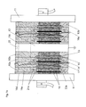
- FIG. 1 An electrolyser module in accordance with an aspect of the present invention is shown generally at 1 in Figures 1 - 3 .
- Figure 1a shows about half of an electrolyser module with 4 cells for illustrative purposes only; the other half of the electrolyser module would be a mirror image (on either side of feature 12, which in this case represents the midpoint of the electrolyser module). In practice, typically greater numbers of cells would be incorporated.
- Figure 1b shows an axial view corresponding to section A-A in Figure 1a , extended to show selected portions of a full electrolyser module
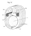
- Figure 1c shows an isometric view of a section of an electrolyser module.
- Electrolyser module 1 includes structural plates 10, end pressure plates 11, intermediate pressure plate 12, anodes 13, cathodes 14, membranes 15, current carriers 16 and bipolar plates 17.
- there are two main types of structural plates 10 cathode structural plates 10a and anode structural plates 10b. Additional special structural plates 10c and 10d are located between the adjacent cathode structural plates 10a, and one side of the intermediate pressure plate 12 and one of the end pressure plates 11, respectively. Suitable sealing gaskets (not shown) also are understood to be included.
- Electrolyser module 1 thus comprises a plurality of electrolysis cells 18 and associated degassing chambers 19.
- the electrolysis cells 18 preferably are located at the bottom part of the electrolyser module 1, and the associated degassing chambers 19 preferably are located at the top part of the electrolyser module 1, surmounting the electrolysis cells 18.
- the electrolysis cells comprise cathode and anode half cell chambers 20a and 20b defined by two adjacent structural plates, as well as a cathode 14, an anode 13, a membrane 15, and the current collectors 16.
- Bipolar plates 17 physically separate and electrically connect adjacent cells. As shown in Figures 1a , 1b and particularly 1c, each cathode half cell chamber 20a is directly connected to the hydrogen degassing chamber 19a by a gas-liquid passage 21 a, and a degassed liquid passage 22a.
- each anode half cell chamber 20b is directly connected to the oxygen degassing chamber 19b by a gas-liquid passage 21b, and a degassed liquid passage 22b. Consequently, the internal fluid flow requirements for electrolyser module 1 are provided for by the features of each half cell, rather than by features extending across all the cells or a large number of cells, such as gas-liquid manifolds and degassed liquid manifolds, which present an increasing pressure drop as their length is increased. Electrolyser module 1 thus is an inherently scaleable structure, in that not only the number of cells and the size of the degassing chambers, but also the fluid circulation capabilities, automatically scale with the number of cells in the electrolyser module.
- electrolyser module 1 does not require a mechanical electrolyte pump(s) to facilitate circulation of fluids between the half cell chambers and the degassing chambers; the fluid flows are driven by gas buoyancy and gravity head, and thus are self-regulating in that they automatically vary with the gas production rates.
- a mechanical electrolyte pump(s) to facilitate circulation of fluids between the half cell chambers and the degassing chambers; the fluid flows are driven by gas buoyancy and gravity head, and thus are self-regulating in that they automatically vary with the gas production rates.
- Most commercial electrolyser modules utilize mechanical electrolyte pumps to facilitate circulation of fluids (electrolyte and electrolyte-gas mixtures) in the electrolyser module.)
- the cell portion of the electrolyser module assembly can generally be as is known in the art.
- the boundaries of each cell are defined by bipolar plates 17, which are thin solid plates made of a suitably conductive and corrosion-resistant material such as nickel to provide electronic conduction of electricity between adjacent cells.
- Electrical connection between bipolar plates 17 and each of the cathode and the anode in a given cell may be accomplished with suitable electronically conducting current carriers 16, which allow for even current carrying and distribution across the faces of the electrodes 13, 14 and bipolar plates 17, as well as relatively unimpeded fluid flow through the half cell chambers 20.
- suitable materials and configurations for current collectors are known in the art, including woven nickel layers or nickel foam.
- the bipolar plates 17 can be dimpled, corrugated, etc., and thereby can provide direct connection between the cathodes 14 and anodes 13 without using separate current carriers 16.
- the dimpled, corrugated, etc. portions can optionally be welded to the cathodes 14 and anodes 13 to provide one-piece sub-assemblies.
- the membranes 15 are located between and in close proximity to or in contact with the respective adjacent cathodes 14 and anodes 13. The membranes 15 thus lie essentially in the middle of the cells 18, and separate the respective anode and cathode half cells.
- the membranes 15 may be micro-porous diaphragms which are fully wetted during operation to exclude gases, or non-porous ion exchange membranes.
- the cathodes 14 and anodes 13 can be as is generally known in the art, for example, catalytic metal coatings coated onto a suitable substrate, for example., nickel mesh.
- Electrical current is supplied to the cell portion of electrolyser module 1 by, for example, a DC power supply, via electrical connections to end pressure plates 11 and optionally intermediate pressure plate 12.
- One possible electrical configuration is shown in Figure 1b , with negative and positive current carrying connections to end pressure plates 11, and a non-current carrying ground connection to intermediate pressure plate 12.
- hydrogen gas is evolved at the cathodes and is released into the cathode half cell chambers 20a, where it forms hydrogen gas-liquid electrolyte mixtures that rise and travel to the hydrogen degassing chamber 19a through the gas-liquid passages 21a.
- oxygen gas is evolved at the anodes and is released into the anode half cell chambers 20b, where it forms oxygen gas-liquid electrolyte mixtures that rise and travel to the oxygen degassing chamber 19b through gas-liquid passages 21b.
- the liquid is separated from the gas in the degassing chambers, and degassed liquid returns to the respective half cell chambers 20a and 20b through degassed liquid passages 22a and 22b.
- Separated hydrogen gas exits through separated hydrogen gas outlet 25 in the hydrogen degassing chamber; separated oxygen gas exits through a similar separated oxygen gas outlet in the oxygen degassing chamber (not shown).
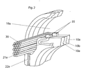
- FIG. 2 Further detail of a hydrogen degassing chamber in the electrolyser module assembly according to the current invention is shown in Figure 2 . Only a section of the hydrogen degassing chamber 19a corresponding to a few structural plates 10) is shown in Figure 2 , which is for illustrative purposes only.
- the configuration and size of the oxygen degassing chamber 19b can be, but are not necessarily, similar to those of the hydrogen degassing chamber 19a. It is to be understood that the use of more than one hydrogen degassing chamber and similarly the use of more than one oxygen degassing chamber can be contemplated.
- the degassing chamber volume is defined by the series of adjacent degassing chamber openings (19a or 19b) in the plurality of structural plates 10.
- Cooling coils 30 for cooling the incoming gas-liquid mixtures as may be required are located in the lower section of the degassing chambers 19a and 19b.
- the electrolyser module 1 includes respective gas discharge and feed water passages extending therethrough and fluidly communicating with the degassing chambers 19a and 19b for gas discharge from each degassing chamber and for feed water introduction into at least one of the degassing chambers, preferably the hydrogen degassing chamber 19a (since water is consumed in the cathodic hydrogen generation reaction).
- Water addition means add water through the feed water passages as required to one or more of degassing chambers 19a and 19b, where the added water is mixed thoroughly with electrolyte before distribution to the half cell chambers 20a and 20b (via degassed liquid passages 22a and 22b).
- the degassing chamber 19a has multiple functions: firstly, to separate the incoming gas-liquid mixtures into separated gas and separated liquid; also, to cool the fluids as may be required, for example to maintain appropriate cell operating temperatures; and further, to provide a volume for mixing of feed water with electrolyte before distribution to the respective half cell chambers.
- the gas-liquid mixture from the corresponding cathode half cell chambers enters the hydrogen degassing chamber 19a from gas-liquid passages 21a.
- gas-liquid passages 21a Although only one gas-liquid passage per cathode half cell is shown, it is understood that a plurality of gas-liquid passages per half cell may be used.
- the gas portion of the incoming gas-liquid mixture rises in the degassing chamber volume, and is thereby separated from the liquid portion of the incoming gas-liquid mixture.
- Means for promoting gas-liquid separation such as baffles, also can be used to promote gas-liquid separation in a given degassing chamber volume.
- the separated and partially cooled gas is removed from the degassing chamber 19a in the electrolyser module 1 via at least one separated gas discharge outlet 25 at one or more suitable locations near the top of the degassing chamber 19a.
- the separated and cooled liquid is returned to the cathode half cell chambers via the corresponding degassed liquid passages 22a. Although only one degassed liquid passage per cathode half cell is shown, it is to be understood that a plurality of degassed liquid passages per cathode half cell may be used.
- flow directing means 35 are added to direct the incoming gas-liquid mixture from the gas-liquid passages along the length of the degassing chamber. This configuration is preferred when the point of connection of the gas-liquid passage 22a to degassing chamber 19a lies below the intended range of operating liquid levels.
- Benefits of this configuration include: (i) extensive "automatic” mixing of feed water added to degassing chamber 19a to enable uniform distribution to all the half cells, even when the feed water is introduced above the liquid level; (ii) avoidance of disturbance of the gas layers at the top of degassing chamber 19a by incoming gas-liquid mixtures, and improved gas-liquid separation efficiency; (iii) improved heat transfer coefficients for the cooling coils in degassing chamber 19a; and, (iv) avoidance of excessive gas carry under back to the half cells.
- Fluid flow modeling indicates that without any flow directing means, there is very little flow along the length of degassing chamber 19a.
- the flow directing means 35 as shown comprises a "hood" over the point of entry of gas-liquid mixture into degassing chamber 19a, consisting of at least one and up to three “walls” and a “proof”, with the opening to the degassing chamber corresponding to the intended direction of fluid flow.
- the "walls” and “roof” may be angled or otherwise oriented as may be appropriate to obtain desired fluid flow patterns. While the "hood” structure is relatively easily manufactured and presents relatively little resistance to fluid flow, it is to be understood that other flow directing means can be used, for example, a bent tube extending from the gas-liquid passage into the degassing chamber 19a.
- the electrolyser module corresponding to the embodiment illustrated in Figure 2 is inherently highly scaleable, since the same general fluid flow patterns can be expected over a wide range of the number of cells in the module, and the degassing chamber volume and degassing capacity scale automatically with the number of cells, or more particularly, with the number of structural plates in the electrolyser module. Furthermore, even with few and significantly separated points of feed water addition, and even with feed water introduction via the top of the liquid, good mixing of feed water in the degassing chamber and uniform distribution to the connected half cells can be achieved over a wide range of the number of cells in the electrolyser module. Similarly the cooling capacity of the module also is scalable with the number of cells in the electrolyser module by adding cooling coil length proportionally, and also optionally varying the coolant flow rate.
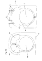
- FIG 3 shows a preferred embodiment in which each structural plate 10 defines one half cell chamber opening 20 and two degassing chamber openings 19a and 19b; it is understood that each structural plate can define more than one of each type of opening.
- Structural plates associated with anode half cells are called anode structural plates, and structural plates associated with cathode half cells are called cathode structural plates.
- Each structural plate 10 also comprises one or more gas-liquid passages 21, which directly connect the top part of the half cell chamber opening 20 to one of the degassing chamber openings 19a and 19b.
- Each structural plate 10 further comprises one or more degassed liquid passages 22, which directly connect the bottom part of the half cell chamber opening 20 to one of the degassing chamber openings 19a and 19b.
- degassed liquid passages 22 Although only one gas-liquid passage 21 and one degassed liquid passage 22 are shown in Figure 3 , it is to be understood that a plurality of each type of passage can also be used.
- the degassing chamber that is directly connected to the anode half cell chamber is an oxygen degassing chamber
- the degassing chamber that is directly connected to the cathode half cell chamber is a hydrogen degassing chamber.
- the degassing chamber openings 19a and 19b may be considered to have an upper section and a lower section. Separated gas rises into the upper section and degassed liquid descends into the lower section.
- the discharge opening of the gas-liquid passage 21 is preferably located to avoid introducing gas into the degassed liquid and liquid into the gas. Accordingly the gas-liquid passages 21 enter the degassing chambers 19a and 19b at a location above the entrance to the degassed liquid passages 22 but below the upper section of the degassing chamber openings 19a and 19b. In other words the discharge opening is therefore in the lower (preferably lowest) region of the upper section.
- the structural plate 10 further comprises a fluid flow directing means 35 at the point of connection of the gas-liquid passage 21 to degassing chamber opening 19a; similar fluid flow directing means can also be used if the gas-liquid passage 21 connects to degassing chamber opening 19b.
- fluid flow directing means 35 comprises a "hood" over the point of connection of the gas-liquid passage 21 to the degassing chamber opening 19a.
- the "hood” consists of at least one and up to three “walls” and a "roof", with an opening corresponding to the intended directions of fluid flow.
- hood structure is relatively easily manufactured, presents relatively little resistance to fluid flow, and does not adversely affect the structural integrity of the surrounding areas, it is to be understood that other fluid flow directing means can be used; for example, a bent tube shape extending from the gas-liquid passage into degassing chamber opening 19a.
- passages for gas-liquid transfer 21 and the degassed liquid passages 22 including; (i) surface channels, i.e., channels defined in the surface of structural plate 10; (ii) internal passages, i.e., passages defined in the interior of structural plate 10; (iii) surface channels that become internal passages in certain sections; and, (iv) internal passages that become surface channels in certain sections.
- the passages are shown as comprising surface passages, except near the points of connection to the half cell chamber opening 20, where the surface passages become internal passages in order to allow for passage under sealing gasket holding features. This approach aids in manufacturability when the passages are long and/or have complex shapes.
- any of the four different passage structures contemplated can be used for any given passage, and combinations of the different approaches for the passages can be used in any given structural plate. It also is to be understood that in the case of surface passages, the passages can be formed in one or both opposing surfaces of adjacent structural plates.
- the gas-liquid passage in a given structural plate can become an internal passage at an appropriate point in its path, and then travel through the width of its structural plate to the opposite face of the structural plate, then through the width of an adjacent structural plate, and finally onto the near face of the next structural plate, where the passage continues its path as a surface passage to the corresponding degassing chamber opening, optionally becoming an internal passage near the point of connection to the degassing chamber opening.
- Appropriate sealing is included at the points where the passage crosses between adjacent structural plates.
- gas-liquid passages and the degassed liquid passages can cross multiple plates. Note that multi-plate configurations also are inherently scaleable, and do not include common internal fluid collection manifolds or external piping for gas-electrolyte or electrolyte transfer.
- the lengths and cross-sectional areas of the passages for gas-liquid transfer 21 and the degassed liquid passages 22 are the primary determinants of stray currents (also known as bypass currents) and the current efficiency of the electrolyser module.
- the main path for current flow in an electrolyser module is through the cells, which is the desired gas-producing path.
- ionic current can flow through the electrolyte in the gas-liquid passages and in the degassed liquid passages.
- the amount of this so-called stray current or bypass current that bypasses the cell path via the gas-liquid passages and the degassed liquid passages depends on the relative resistances of the cell path and the passages.
- stray currents include loss of gas-producing current (lower current efficiency) and potential stray current corrosion of metal (especially steel) parts exposed to electrolyte.
- the resistance of the passages depends on: (i) the length of the passages; (ii) the cross-sectional area of the passages; and, (iii) the void fraction (gas fraction) for the fluids in the passages.
- the lengths and cross-sectional areas of the gas-liquid passages 21 and of the degassed liquid passages 22 also are key determinants of fluid flow rates and void fractions (indicative of the extent of gas hold up) in the electrolyser module. While stray currents decrease as passage lengths are increased and as passage cross sectional areas are decreased, conversely fluid flows are increasingly restricted. Restriction of fluid flows is of course undesirable, and sufficient liquid circulation is required in the electrolyser module, for example, to maintain low void fractions and good heat transfer characteristics. Consequently, design of the electrolyser module requires a compromise between control of stray currents and facilitating good fluid flows.
- the passage cross sectional areas are enlarged by using a "slot" geometry; i.e., although the passage dimension corresponding to the thickness of the structural plate is limited, a slot geometry that is elongated in the perpendicular direction of the same surface can be used to provide a significant cross sectional area, which in turn allows for good fluid flow and circulation in the electrolyser module.
- the corresponding passage length is selected so as to increase the electrical resistances associated with the passage paths, and achieve current efficiencies of, e.g., 99% or higher (i.e., 99% or more of the current passed through the electrolyser module goes through the cells and produces gases).
- the passages can be elongated through the use of various passage path geometries.
- the void fraction in the degassed liquid passages typically can be expected to be very low, and the resistivity of the fluid in the passages will be close to that of the liquid electrolyte.
- the void fraction in the gas-liquid passages typically can be expected to be significant, e.g., 0.1 to 0.5, during operation of the electrolyser module.
- the degassed liquid passages typically are longer and/or have a smaller cross-sectional area than the gas-liquid passages.
- a greater number of gas-liquid passages can be used.
- the use of complex passage configurations may be required in order to attain high current efficiencies; this is most important for large electrolyser modules with high gas production capacities and correspondingly large passage cross sectional areas.
- the ratio of maximum hydrogen generation rate per half cell i.e., the maximum hydrogen flow rate through the gas-liquid passage (in Nm 3 /h) to the cross sectional area of the gas-liquid passage (in cm 2 ) is 0.83, (maximum hydrogen generation rate per hydrogen half cell of 2.5 Nm 3 /h and cross sectional area of the gas-liquid passage of 3 cm 2 ) and the passage aspect ratio, i.e., the ratio of the length of the gas-liquid passage to its cross sectional area is 23. In cases where the cross sectional area of the gas-liquid passage varies or there is more than one gas-liquid passage, an average value could be used as an estimate.
- Electrolyser module designs with significantly larger values of these ratios can be considered to have significantly restricted fluid flows and fluid circulation, and concomitant potentially serious issues with heat removal from and excessive voiding of the half cell chambers.
- a recommended maximum value for the ratio of the maximum hydrogen generation rate (in Nm 3 /h) to the cross sectional area of the gas-liquid passage (in cm 2 ) is about 2.
- a recommended maximum value of the aspect ratio of the hydrogen gas-liquid passage is about 30.
- FIG. 4 Examples of structural plates 10 for an electrolyser module according to the current invention with different passage configurations are shown in Figure 4 .
- Most of the lengths of the passages are surface passages, which enables the use of long passages with complex shapes.
- the surface passages can optionally become internal passages in the vicinities of the points of connection to the half cell chamber opening 20 and to the degassing chamber opening 19a to facilitate holding features for locating and holding sealing gaskets.
- the gas-liquid passage 21i extends from the top part of half cell chamber opening 20 upward and over the top of the degassing chamber opening 19a, before connecting to the bottom part of the degassing chamber opening 19a.
- the degassed liquid passage 22i extends from the opposite side of degassing chamber opening 19a, down and around the periphery of the half cell chamber opening 20 on the same side of the structural plate before connecting to the bottom part of the half cell chamber 20.
- the gas-liquid passage 21ii extends from the top part of the half cell chamber 20 substantially vertically upward from the half cell chamber opening, and then returns substantially downward before connecting to the bottom part of the degassing chamber opening 19a.
- the gas-liquid passage 21iii extends from the top part of half cell chamber opening 20 and under the corresponding degassing chamber opening 19a, joining the bottom part of the degassing chamber opening 19a at the far side.
- the degassed liquid passage 22iii extends from the opposite side of the degassing chamber opening 19a, down and around the periphery of the half cell chamber opening 20 on the opposite side of the structural plate before connecting to the bottom part of the half cell chamber opening 20.
- the gas-liquid passage 21iv extends from the top part of the half cell chamber opening 20 and part way under the corresponding degassing chamber opening 19a, then doubles back over itself before joining the bottom part of the degassing chamber opening 19a at the near side.
- the structural plates 10 preferably are made of a suitable electrically insulating polymeric material that is inert to electrolyte (e.g., an aqueous solution of 25% to 35% KOH) and gases (e.g., oxygen, hydrogen, nitrogen, or chlorine), as well as other potential materials to which it may be exposed, such as ammonium hydroxide.
- gases e.g., oxygen, hydrogen, nitrogen, or chlorine
- suitable thermoplastic materials include polyphenylene oxide (PPO), polyphenylene sulphide (PPS) and the like, and in particular polysulfone.
- Thermoset polymeric materials also may be used. Fibre reinforced plastics may also be used.
- the plates may be manufactured by conventional molding techniques, such as injection molding or casting, or by conventional machining techniques, such as milling and drilling.
- Manufacturing by molding techniques enables consideration of reduction of material in the structural plates 10 through inclusion of additional openings, coring, or the like (for moldability, weight, cost, and potential strain relief considerations), as well as the use of complex shapes for the body, the half cell chamber openings, the degassing chamber openings, the gas-liquid passages, and the degassed liquid passages.
- stray current blocking walls can be straightforwardly added to the bottom portion of one or more of the degassing chamber openings (extending at higher than the highest anticipated operating liquid level) of special structural plates that can be used at appropriate points in an electrolyser module to control stray current flows.
- forming of structural plates in multiple portions that can be interconnected or joined to form a complete structural plate also is contemplated.
- the structural plates further comprise first and second opposing surfaces which define holding features for locating and holding functional cell components, including electrodes (anodes and cathodes), membranes, and bipolar plates.
- These holding features enable proper location and alignment of functional components in an assembled electrolyser module.
- Each holding feature for a given functional component comprises an "L" shaped seat, which surrounds the corresponding half cell chamber opening.
- Each "L" shaped seat comprises a seat back and a seat wall, which preferably are orthogonal to one another.
- Each "L” shaped seat faces inward toward the half cell chamber opening.
- the functional components are sized to "sit" fully in the seats, such that one planar surface of the electrode, membrane or bipolar plate is generally in the same plane as the surface of the structural plate in which it is supported.
- the structural plates further comprise first and second opposing surfaces which define holding features for locating and holding sealing gaskets.
- the seals may be as is known in the art to prevent leakage of gas, liquid, or gas-liquid mixtures (a) from inside the electrolyser module to the outside; and, (b) from inside the chambers or passages in which they are contained.
- Such seals may include, but are not limited to, for example flat gaskets or preferably o-rings.
- other features such as ribs may be added to one or more of the opposing surfaces.
- interlocking features or crush ribs without sealing gaskets, may also be used.
- the main holding features for locating and holding sealing gaskets are firstly those surrounding all or at least part of one or more of degassing chamber openings, those surrounding the half cell chamber opening, and also the main exterior seals surrounding all the fluid-containing volumes, including all of the two or more degassing chamber openings, the half cell chamber opening, the one or more gas-liquid passages and the one or more degassed liquid passages.
- the use of multiple seals and holding features for locating and holding sealing gaskets also can be contemplated.
- the first surface of one structural plate is aligned with the second surface of the adjacent structural plate such that the functional components and sealing gaskets are aligned with their respective holding features, in order that cathodes 14, membranes 15, and anodes 13 are supported by their respective structural plates, and the half cell chambers, degassing chambers, and the perimeter of the electrolyser module are sufficiently sealed.
- the sizing of the structural plate 10 in the embodiments of Figures 3 and 4 depends on the required sizes and shapes of the half cell chamber opening, degassing chamber openings, and to some extent, on the required sizes and paths of the gas-liquid passages and the degassed liquid passages.
- the half cell chamber opening is sized according to the required or appropriate active electrode area for a given operating range of current densities and number of cells in the electrolyser module.
- the anode and cathode nominal (projected geometric) surface areas, as well as the nominal membrane surface areas, generally are maintained equal, but this is not necessarily a requirement.
- the sizes, shapes and configurations of the degassing chamber openings and the gas-liquid passages and for degassed liquid passages are then subsequently sized as required to obtain target liquid flow rates, void fractions, and gas-liquid separation efficiency.
- the overall thickness of the structural plate 10 in the embodiments of Figures 3 and 4 may vary depending on the application, part diameter, material(s) of construction, operating pressure, operating temperature, manufacturing method, etc., but must be sufficient to accommodate the gas-liquid passage 19 and degassed liquid passage 22.
- the overall thickness may be in the range of 0.4 to 1.5 cm, and more preferably, 1.0 to 1.5 cm for larger diameter structural plates.
- the actual plastic thickness at any given point in a larger diameter structural plate typically is less than the overall part thickness, due to manufacturability considerations (e.g., for manufacturing by injection molding).
- the body of structural plate 10 In general, shapes without sharp corners are preferred for the body of structural plate 10, the half cell chamber opening 20, and the degassing chamber openings 19a and 19b in the embodiments of Figures 3 and 4 , in order to avoid stress concentrations.
- Specific shapes depend on the design requirements, for example to accommodate different passage paths, to achieve required structural strength, and to accommodate sizes required to achieve good fluid flows and gas-liquid separation, etc.
- the degassing chamber openings 19a and 19b preferably have an irregular shape with rounded corners, but also may have a rectilinear shape with rounded corners or a rounded shape.
- Electrolyser module 1 is shown in the embodiment of Figure 1b as being held together between end pressure plates 11 on either end.
- a number of tie rod assemblies using Belleville washer stacks with the tie rods located either around the outside of the main body of the electrolyser module, and/or going through the body of the electrolyser module, can be used to maintain sealing pressure on the module.
- the end pressure plates 11 comprise a body and can be made of steel, stainless steel, nickel-plated steel, nickel-plated stainless steel, nickel, or nickel alloy.
- the bodies of the end pressure plates 11 are electrically conducting, and typically are used to facilitate electrical connection to electrolyser module 1, using appropriate electrical connection means as are known in the art.
- Electrode current as applied to the cell portions of electrolyser module 1 by, for example an external DC power supply passes through the end pressure plates as electronic current, then through the adjacent current carrier 16 to the cathode 14, where electrons react with water to produce hydrogen and hydroxyl ions.
- the hydroxyl ions carry the current through the membrane 15 to the anode 13, where hydroxyl ions react to produce oxygen, water, and electrons.
- the current then passes as electrons through the adjacent current carrier 16 to, and then through the bipolar plate 17 to the adjacent cell.
- Analogous processes occur at the intermediate pressure plate 12, and also at the other end of the electrolyser module 1 (not shown), where electrons pass through the metallic end pressure plate 11 and then back to the external DC power supply to complete the electrical circuit.
- one of the end pressure plates 11 and one side of the intermediate pressure plate 12 are used directly to define one side of the end (adjacent) half cell chambers (defined by bipolar plates 17 or intermediate pressure plate 12 in the other half cells).
- Special structural plates 10d and 10c are placed adjacent to the other end pressure plate 11 and the other side of the intermediate pressure plate 12, respectively. These special structural plates do not have gas-liquid passages 21 or degassing passages 22.
- the special structural plates 10d next to the end pressure plates 11 have half cell chamber openings 20, but do not have degassing chamber openings 19.
- the special structural plates 10c next to the intermediate pressure plates 12 have half cell chamber openings 20 and degassing chamber openings 19.
- the purpose of the special structural plates is to provide an opposing insulating face opposite the channels in the surfaces of the adjacent structural plates 10a to form the gas-liquid passages and the degassed liquid passages.
- the end pressure plate and the intermediate pressure plate can be used directly to define one side of the adjacent half cell chambers (by using correspondingly thicker single current carriers 16).
- bipolar plates 17 can be seated in the special structural plates 10d and 10c to define one side of the adjacent half cell chambers.
- thinner current carriers can be used to provide electrical connection between the bipolar plates 17, and the adjacent end pressure plates 11 and the intermediate pressure plate 12.
- this configuration can be used at both end plates 11, and on either side of the intermediate pressure plate(s) 12.
- This alternative embodiment is advantageous in that the bodies of the end pressure plates 11 and the intermediate pressure plates 12 are not exposed to potentially corrosive electrolyte.
- appropriately sized nickel sheets or plates may be inserted into holding features in the special structural plates 10c and 10d located adjacent to the end plates and the one or more intermediate plates, or alternatively in recesses in the bodies of the end pressure plates and also on both opposite faces of the one or more intermediate pressure plates, the nickel sheets or plates thereby being located so as to face and correspond to the adjacent half cell chambers.
- Appropriate sealing may also be used to ensure that electrolyte contact is limited to the nickel sheets or plates.
- This alternative embodiment also is advantageous in that the bodies of the end pressure plates 11 and the intermediate pressure plates 12 are not exposed to potentially corrosive electrolyte.
- the degassing chamber openings in the intermediate pressure plates 12 also can include an insulating insert or sleeve, or alternatively, can be coated with an insulating material.
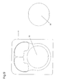
- Figure 9 is a front view illustrating an end pressure plate II utilizing a nickel plated insert 30 mounted within a recess 32 as suggested above.
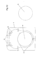
- Figures 10 and 11 are front views illustrating an intermediate pressure plate 12 utilizing a nickel plated insert 40 received in a through hole 42 and retained by retaining tabs 44 secured to the intermediate pressure plate 12.
- one or more intermediate pressure plates 12 are also included in the electrolyser module; in the case of one intermediate pressure plate 12, it is preferably located at the midpoint of the electrolyser module (i.e., with an equal number of cells on either side).
- the body of the intermediate pressure plate 12 is electrically conducting, and typically is used to facilitate electrical connections to electrolyser module 1. These electrical connections can be current carrying power connections, or non-current carrying connections for grounding purposes only.
- connections for external piping e.g., for coolant circulation, feed water addition, product gas discharge outlets, inert gas introduction, connection of the lower sections of the degassing chambers, and drains can be made to the one or more of the end pressure plates 11 and intermediate pressure plates 12.
- the lower sections of the degassing chambers can be connected by passages in the body of the one or more intermediate pressure plates 12 or the body of one or both end pressure plates 11. Additional intermediate pressure plates 12 can be included, located so as to divide the total number of electrolysis cells into sections containing equal numbers of cells, depending on the configuration for electrical connections to the electrolyser module 1.
- a function of the intermediate plates 12 is to provide a location for withdrawl of gas from the gas liquid separator chambers on either side thereof. This may be achieved with through holes 50 which in effect are "banjo" fittings mounted between opposite sides of the intermediate plates 12.
- the through holes 50 fluidly communicate with the gas liquid separator chambers 19a and 19b on opposite sides thereof and with fluid conduits 52 extending generally radially from the intermediate pressure plate 11.
- the intermediate pressure plates 12 comprise a body that can be made of steel, stainless steel, nickel-plated steel, nickel-plated stainless steel, nickel, or nickel alloy. Two or more degassing chamber openings are defined in the body, typically, but not necessarily, corresponding to the degassing chamber openings in the structural plates used in the same electrolyser module.
- the intermediate pressure plates 12 also can include protective plastic or reinforced plastic inserts fitted into the degassing chamber openings, to protect the body material against stray current corrosion.
- the inserts also can incorporate stray current blocking walls, which are walls of electrically insulating material such as plastic that block most of one or more of the degassing chamber openings in the intermediate pressure plate 12, leaving some open space near the top of the degassing chamber openings to allow for gas flow. Stray current blocking walls also can be located in any of the structural plates 10 in the electrolyser module 1, although the intermediate pressure plates 12 are a preferred location, so as to avoid interference with feed water mixing by stray current blocking walls at points intermediate to feed water addition
- the intermediate pressure plates 12 preferably divide the total number of cells into sections of equal numbers of cells, and furthermore, alternating negative and positive electrical power connections to the intermediate pressure plates 12 are located such that negative and positive electrical power connections alternate over the length of the electrolyser module 1.
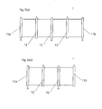
- Examples of electrical power connection configurations are depicted schematically in Figures 5(i) to 5(iv) : (i) negative electrical power connection to one end pressure plate 11a and positive electrical power connection to the other end pressure plate 11b of the electrolyser module 1; (ii) negative electrical power connection to one end pressure plate 11a and positive electrical power connection to the other end pressure plate 11b, with a non-current carrying electrical ground connection to an intermediate pressure plate 12 at the midpoint of the electrolyser module 1; (iii) negative electrical power connections to the end pressure plates 11a and 11b, and positive electrical power connection to an intermediate pressure plate 12 at the midpoint of electrolyser module 1; and, (iv) positive electrical power connections to the end pressure plates 11a and 11b, and negative electrical power connection to an intermediate plate 12 at the midpoint of the electrolyser module 1.
- the negative electrical power connections can be connected to the same electrical ground.
- One or more power supplies AC to DC converters and/or DC to DC converters
- AC to DC converters and/or DC to DC converters can be used to supply DC electricity to an electrolyser module via the electrical power connection configurations described above.
- each degassing chamber has one or more gas outlets, which are located in one or more intermediate pressure plates, or in one or both end pressure plates;
- the degassing chambers can contain one or more sets of cooling coils, which are connected to one or more external coolant circulation loops through one or more intermediate pressure plates, or through one or both end pressure plates;
- the degassing chambers can contain means of adding feed water, which are connected to one or more intermediate pressure plates, or one or both end pressure plates;
- sensors for level, temperature, pressure, or other measurements
- sensor reservoirs are connected to the degassing chambers through one or more intermediate pressure plates, or through one or both end pressure plates; and, (e) the lower sections of the degassing chambers are connected to one another by external piping through one or more intermediate pressure plates or through one or both end pressure plates.
- Figures 6(i) and 6(ii) show side views of two alternative sets of structural plates, each set being comprised of a cathode structural plate (10a(i) and 10a(ii)) and an anode structural plate (10b(i) and 10b(ii)).
- the part of the structural plates shown is at the top of the half cells and slightly above.
- the first surface of the anode structural plate 10b(i) includes two seats, the first innermost seat being for seating anode 13, the second or outermost seat being for seating membrane 15, which defines one side of the corresponding half cell.
- the opposing surface in an assembled electrolyser module is the first surface of the cathode structural plate 10a(i), which includes one seat for the seating cathode 14.
- the cathode 14 and the anode 13 thereby "sandwich" and support the membrane 15 on either side.
- the second surface of the cathode structural plate 10b(i) includes a seat for the bipolar plate 17, which defines the other side of the corresponding half cell, electrically connected to cathode 14 by the current carrier 16.
- the opposing surface is the second surface of another anode structural plate 10b(i), which in this embodiment does not include any seats for the functional components.
- the structural plates 10a(i) and 10b(i) have arbitrarily been deemed cathode and anode structural plates, respectively. It should be understood that these can also be anode and cathode structural plates, respectively.
- sealing gaskets (not shown) can be used for sealing the membrane 15 and the bipolar plate 17, in which case the structural plates further comprise the corresponding holding features for locating and holding the sealing gaskets.
- the functional component holding features are the same in the cathode and anode structural plates.
- the membrane seats in the first surfaces and the bipolar plate seats in the second surfaces each effectively are "half seats", which also incorporate holding features for sealing gaskets to seal both faces of the membranes and the bipolar plates.
- cathode structural plate 10a(ii) can be flipped around and used in the opposite orientation as anode structural plate 10b(ii), which is the mirror image of cathode structural plate 10a(ii), in order that only a single part need be manufactured (with the exception of optional special structural plates, such as special structural plates for placement next to end pressure plates or intermediate pressure plates, or structural plates with stray current blocking walls).
- the gas-liquid passages and the degassed liquid passages can be completely internal passages.
- Manufacture of such plates with completely internal passages can be accomplished by, for example, molding the structural plate in two parts, a first part and a second part.
- the face area of each of the first part and the second part corresponds to the full face area of the structural plate, and the sum of the thickness of the first part plus the thickness of the second part makes up the full thickness of the structural plate.
- Each of the first part and the second part has an outer end face and an inner end face, the outer end faces comprising the features of the end faces of the structural plate, and the inner end faces comprising opposite halves of the gas-liquid passages and the degassed liquid passages.
- the inner faces of the first part and the second part can be bonded together by means known in the art to form structural plates with gas-liquid passages and degassed liquid passage that are completely internal to the structural plates. If the gas-liquid passages and the degassed liquid passages further lie completely on one side of the vertical center line of the structural plate, then only a single type of structural plate need be used (with the exception of optional special structural plates, such as end structural plates, or structural plates with stray current blocking walls).
- Embodiments of draining systems for draining of the electrolyser module are as described below.
- the draining system drains electrolyte from the cathode half cell chambers and the anode half cell chamber, for purposes such as long term shut down, maintenance, transport, etc. It should be noted that the draining system does not affect the electrolyser module during periods of operation, and can be considered as an independent part of the electrolyser module in this regard.
- the draining system comprises two separate draining systems, a cathode draining system for the cathode half cells, and an anode draining system for the anode half cells.
- each of the cathode and anode draining systems comprise a plurality of connecting draining passages connecting the bottom portions of either each of the cathode half cell chambers or each of the anode half cell chambers to one or more draining manifolds. Note that by draining the half cell chambers, the corresponding degassing chambers also are drained, since they are connected to the half cell chambers by the degassed liquid passages and the gas-liquid passages.
- the cathode and anode draining systems can be, but are not necessarily, similar. The cathode draining system will be described here for illustrative purposes..
- the cathode draining passages comprise long passages with relatively small cross sectional areas connecting the bottom portion of the cathode half cell chambers with one or more cathode draining manifolds.
- the cathode draining manifolds are located below the cathode half cell chambers in order that draining can be achieved by gravity head, and extend at least part way along the length of the electrolyser module.
- the lengths of the draining passages for the cathode half cells can be extended by using paths comprised in more than one structural plate.
- the draining passages are internal passages near the bottom part of the cathode half cell chamber, which then become surface passages that follow a long downward path in order to render stray current flows during operation negligible.
- the passage then travels through one of the adjacent anode plates to the next cathode plate, where it once again becomes a surface passage with a long path, before joining one of the cathode draining manifolds.
- More than one cathode draining manifold can be used in order to further limit stray current flows.
- the one or more cathode draining manifolds connect to a draining point.
- the draining point comprises a draining port with a valve, located in the bottom portion of one of the intermediate pressure plates or one of the end pressure plates. There can be more than one draining point in the electrolyser module.
- each of the cathode and anode draining systems also comprise draining channels for each half cell.
- similar approaches are used for both the cathode and anode draining systems.
- the cathode draining system will be described here for illustrative purposes.
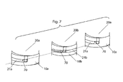
- the main features of the cathode draining system are shown in Figure 7 , which shows a series of three adjacent structural plates (two cathode structural plates and one anode structural plate) in the electrolyser module.
- the starting point of the cathode draining passage 70 for each cathode half cell is located in the degassed liquid passage 22a, near its point of connection to the cathode half cell chamber opening 20a.
- the cathode draining passage 70 is connected directly at or near the bottom of the cathode half cell chamber opening 20a.
- the cathode draining passage 70 initially is an internal passage, passing through the thickness of the cathode structural plate 10a to the opposing face of adjacent anode structural plate 10b, where it becomes a surface passage that creates a long path in order to render stray current flows during operation negligible.
- the periphery of the area defined by the surface passages in the face of anode structural plate 10b is sealed, preferably by an o-ring (not shown) that is seated in a holding feature (not shown).
- the cathode draining passage 70 then once again becomes an internal passage, passing through the thickness of anode structural plate 10b to degassed liquid passage 21a in the adjacent cathode structural plate 10a.
- This multi-structural plate configuration is then repeated until a draining point is reached.
- the draining point comprises a draining port with internal channels connecting to a valve, located in the bottom portion of one of the intermediate pressure plates 12 or one of the end pressure plates 11. There can be more than one draining point in the electrolyser module.
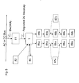
- FIG. 8 shows a schematic diagram of an electrolyser system according to the current invention.
- the electrolyser module 1 is electrically connected to a source of electricity (electric power) according to any of the general electrical connection configurations described herein.
- the electricity supplied generally is DC electricity from a power supply 81, which can be, for example, a DC-DC converter to provide regulated DC electricity from a DC bus, or an AC-DC converter to provide regulated DC electricity from an AC bus;
- the primary electricity source can be an electricity grid, and/or other sources, such as a wind turbine or wind farm, or solar array or solar farm, optionally including some or all of equipment for intermediate processes such as electricity transmission, transformation, and "unregulated" rectification.
- the electrolyser module 1 is also connected to a feed water source 82, typically with intermediate feed water purification, e.g., by reverse osmosis and/or ion exchange units.
- the electrolyser module 1 is further connected to a coolant source 83, which may comprise a coolant reservoir with a chiller or other means of heat removal, as well as coolant circulation and flow rate control means.
- the hydrogen gas outlet may be connected to a buffer volume 84a at the desired pressure for any downstream application or storage; a similar buffer volume 84b also can be used for the oxygen gas outlet.
- buffer volumes can be useful for enabling continuous flow of gases from the electrolyser module 1 at varying flow rates.
- demisting means 85a and 85b can be used to remove mist from the hydrogen gas, and also preferably from the oxygen gas, respectively.
- Separate demisting means are used for the hydrogen gas stream and the oxygen gas stream.
- the demisting means can be located at any point between the respective gas outlets from electrolyser module 1 and buffer volumes 84a and 84b. Passages or conduits for return of collected liquid from the demisters to the corresponding hydrogen or oxygen degassing chamber also can be included. Further, the demisting means can be integrated into the degassing chambers.
- the exiting product hydrogen gas and/or oxygen gas can also be contacted with feed water to improve demisting efficiency and to facilitate return of removed electrolyte mist.
- the electrolyser system may further comprise gas conditioning (gas purification) means for hydrogen 86a, and/or oxygen, 86b, which may comprise, e.g., catalytic purifiers and driers.
- Gas conditioning (gas purification) means for hydrogen 86a, and/or oxygen, 86b may comprise, e.g., catalytic purifiers and driers.
- Hydrogen compression means 87a and/or oxygen compression means 87b may be included according to downstream pressure requirements, and can be located either upstream or downstream of the gas conditioning means 86a and/or 86b, depending on the pressure of the gas produced by electrolyser module 1.
- Hydrogen transmission and/or storage means 88a and/or oxygen storage means 88b can optionally be included if there is a need to store excess hydrogen and/or oxygen for future use.
- Users 89a and 89b can be the same entity, and can include, for example, industrial processes using hydrogen and/or oxygen, hydrogen fuel dispensing systems for hydrogen-powered vehicles
- the inherently scalable electrolyser module generally produces hydrogen gas and oxygen gas by first generating the hydrogen gas and oxygen gas in the plurality of electrolytic cells contained in the electrolyser module.
- the hydrogen gas-electrolyte mixtures are transferred directly from the top part of each cathode half cell chamber to a bottom part of an upper section of one or more hydrogen degassing chambers that are integrally contained in the electrolyser module structure, through respective gas-liquid transfer passages extending directly from each cathode half cell chamber to the one or more hydrogen degassing chambers.
- the hydrogen gas-electrolyte mixture streams from each of the cathode half cells are directed longitudinally along the length of the one or more hydrogen degassing chambers, in order to promote heat transfer to the cooling coils and to promote mixing of feed water additions.
- the hydrogen gas is separated from the liquid electrolyte in the one or more hydrogen degassing chambers to produce hydrogen gas and degassed electrolyte.
- the resulting hydrogen gas is removed from the top part of the one or more hydrogen degassing chambers, and the degassed electrolyte is transferred directly from the bottom part of the lower section of one or more hydrogen degassing chambers to the bottom part of the cathode half cell chamber through degassed liquid passages directly connecting the one or more hydrogen degassing chambers to each cathode half cell chamber.
- the oxygen gas-electrolyte mixtures are transferred directly from the top part of each anode half cell chamber to the bottom part of the upper section of one or more oxygen degassing chambers that are integrally contained in the electrolyser module structure, through respective gas-liquid transfer passages extending directly from each anode half cell chamber to the one or more oxygen degassing chambers.
- the oxygen gas-electrolyte mixture streams from each of the anode half cells are directed longitudinally along the length of the one or more oxygen degassing chambers, in order to promote heat transfer to the cooling coils and to promote mixing of any feed water additions.
- the oxygen gas is separated from the liquid electrolyte in the one or more oxygen degassing chambers to produce oxygen gas and degassed electrolyte.
- the resulting oxygen gas is removed from the top part of the one or more oxygen degassing chambers, and the degassed electrolyte is transferred directly from the bottom part of the lower section of the one or more oxygen degassing chambers to the bottom part of the anode half cell chamber through degassed liquid passages directly connecting the one or more oxygen degassing chambers to each anode half cell chamber.
- the above process also is applicable for alkaline ammonia electrolysis, in which the inherently scalable electrolyser module produces hydrogen gas and nitrogen gas (instead of oxygen gas), and ammonium hydroxide is present in / added to the anolyte (anode side electrolyte).
- the oxygen degassing chamber would be a nitrogen degassing chamber in alkaline ammonia electrolysis.
- the contemplated operating pressure of the electrolyser module according to the present invention lies between atmospheric pressure and 3 MPa, depending on the application requirements and the pressure holding capability of the electrolyser module structure.
- no additional pressure containment means such as a pressure vessel surrounding the electrolyser module, or load bearing reinforcing support or shell/sleeve is utilized. Reinforcement of each structural plate can be considered to maintain inherent scalability of the electrolyser module.
- the interior pressure of the electrolyser module is increased to the intended operating pressure prior to initial start up by introducing pressurized inert gas into the electrolyser module.
- the term initial start up is understood to include any start up after depressurization of the electrolyser module is required. Examples of suitable inert gases are nitrogen, argon and helium.
- liquid level during non-operational periods is lower than where the gas-liquid passage(s) and the degassed liquid passage(s) in each of the structural plates meets the degassing chamber, but is higher than the top of the half cell chamber. In this way, a break in the electrolyte path between half cell chambers is provided, while ensuring that the half cell chambers remain filled, and the membranes remain fully wetted.
- EXAMPLE 1 The fluid flows in a six-cell electrolyser module according to the present invention were modeled by computational fluid dynamics (CFD). For simplicity, the fluid flows on the hydrogen (cathodes) side only are described herein.
- the general structural plate configuration was as shown in Figure 3 , in which the gas-liquid passage 21 extends from the top part of half cell chamber opening 20 and partway under corresponding degassing chamber opening 19a, then doubles back over itself before joining the bottom part of degassing chamber opening 19a at the near side.
- the cell active area was 6,000 cm 2 .
- the hydrogen gas-liquid separation chamber was comprised of a main section 30 cm x 50 cm x 13.2 cm.
- the cross sectional area of the gas-liquid passages and the degassed liquid passages was 3 cm 2 .
- Simulations for current densities from 100 mA/cm 2 to 1,000 mA/cm 2 showed: (a) good gas-liquid separation efficiency, with negligible gas carry under to the half cell chamber; (b) high liquid circulation rates; (c) low void fractions at the top of the cathode half cell chamber; and, (d) current efficiencies of 99%.
- the liquid circulation rates and void fractions for each of the six cathode half cells were within 2% of each other, which is indicative of inherent scalability.
- EXAMPLE 2 Next, the number of cells in the electrolyser module of Example 1 was increased to 50 cells.
- the fluid flows in the 50-cell electrolyser module were modeled by CFD. For simplicity, the fluid flows on the hydrogen (cathodes) side only are described herein.
- the results for each half cell were similar to those obtained for half cells in the six-cell electrolyser module, demonstrating the inherent scalability of the design.
- fluid flow rates in any of the degassed liquid passages in the 50-cell electrolyser module were within 6% of fluid flow rates in any of the degassed liquid passages in the six-cell electrolyser module.
- fluid flow rates in degassed liquid passages were higher in the 50-cell electrolyser module than in the six-cell electrolyser module, and (ii) the fluid flow rates in the degassed liquid passages for each of the 50 cathode half cells were within 1% of each other.
- void fractions at the tops of the 50 cathode half cell chambers were almost equal, and also were within 5% of the void fractions at the tops of any of the cathode half cell chambers in the six-cell electrolyser module.
- EXAMPLE 3 the number of cells in the electrolyser module of Example 2 was increased to 200 cells.
- the fluid flows in the 200-cell electrolyser module were modeled by CFD. For simplicity, the fluid flows on the hydrogen (cathodes) side only are described herein.
- the results for each half cell were similar to those obtained for half cells in six-cell and 50-cell electrolyser modules, demonstrating the inherent scalability of the design.
- the range of fluid flow rates in the degassed liquid passages in the 200-cell electrolyser module was identical to the range of fluid flow rates in the degassed liquid passages in the 50-cell electrolyser module.
- void fractions at the tops of the 200 cathode half cell chambers were almost equal, and also were almost equal to the void fractions at the tops of the cathode half cell chambers in the 50-cell electrolyser module.
- the present electrolyser modules can be used in the production of various gases, for example chlorine and hydrogen by the electrolysis of brine, nitrogen and hydrogen by the electrolysis of ammonia, or oxygen and hydrogen in the case of electrolysis of water.
- gases for example chlorine and hydrogen by the electrolysis of brine, nitrogen and hydrogen by the electrolysis of ammonia, or oxygen and hydrogen in the case of electrolysis of water.
- the preferred embodiments of the invention described herein concern the electrolysis of water where the hydrogen-liquid and oxygen-liquid mixtures are generated in the respective half cell chambers.
- electrolyser module of the present invention be used for large scale (e.g., MW scale), high pressure applications.
Landscapes
- Chemical & Material Sciences (AREA)
- Engineering & Computer Science (AREA)
- Chemical Kinetics & Catalysis (AREA)
- Electrochemistry (AREA)
- Materials Engineering (AREA)
- Metallurgy (AREA)
- Organic Chemistry (AREA)
- Inorganic Chemistry (AREA)
- Electrolytic Production Of Non-Metals, Compounds, Apparatuses Therefor (AREA)
Claims (35)
- Module électrolyseur comprenant une pluralité de plaques de structure dont chacune a une paroi latérale s'étendant entre des faces d'extrémité opposées avec une ouverture sur chambre hémicellulaire et au moins deux ouvertures de chambre de dégazage s'étendant à travers ladite plaque de structure entre lesdites faces d'extrémité opposées ;
lesdites plaques de structure étant disposées en juxtaposition face à face entre des plaques opposées de pression d'extrémité,
chacune desdites ouvertures sur chambre hémicellulaire logeant au moins partiellement des composants électrolytiques hémicellulaires comprenant au moins une électrode, une plaque bipolaire en communication électrique avec ladite électrode et une membrane, lesdites plaques de structure et les composants hémicellulaires définissant une rangée de cellules électrolytiques branchées en série surmontée par au moins de première et deuxième chambres de dégazage dont chacune a une section supérieure au-dessus d'une section inférieure ; lesdites plaques de structure définissant au moins, lorsqu'elle sont dans ladite juxtaposition face à face, des passages respectifs gaz-liquide s'étendant entre une partie supérieure des chambres hémicellulaires et une partie inférieure de ladite section supérieure desdites première et deuxième chambres de dégazage pour procurer une communication fluidique entre une partie anode desdites cellules électrolytiques et ladite première chambre de dégazage et entre une partie cathode desdites cellules électrolytiques et ladite deuxième chambre de dégazage ; lesdites plaques de structure définissant en outre au moins quand elles sont dans ladite juxtaposition face à face, des passages respectifs pour liquide dégazé s'étendant entre une partie inférieure desdites première et deuxième chambres de dégazage et une partie inférieure de ladite section inférieure desdites chambres hémicellulaires pour le retour de liquide dégazé desdites première et deuxième chambres de dégazage respectivement auxdites parties d'anode et de cathode desdites cellules électrolytiques ;
ledit module électrolyseur comprenant en outre des passages respectifs de décharge de gaz pour eau d'alimentation s'étendant à travers celui-ci et communiquant fluidiquement avec lesdites chambres de dégazage pour une évacuation de gaz à partir desdites chambres de dégazage et pour l'introduction d'eau d'alimentation dans lesdites chambres de dégazage, et
le module électrolyseur comprenant aussi au moins une bobine de refroidissement ou des tubes de refroidissement dans au moins soit ladite première soit ladite deuxième chambre de dégazage. - Module électrolyseur selon la revendication 1, comprenant en outre au moins une plaque de pression intermédiaire intercalée entre lesdites plaques de structure le long de ladite longueur dudit module électrolyseur ; chacune desdites au moins une plaque de pression intermédiaire comprenant des faces d'extrémité opposées avec une paroi latérale s'étendant entre elles, ladite plaque de pression intermédiaire définissant au moins de première et deuxième ouvertures de dégazage s'étendant entre ses faces d'extrémité opposées pour communiquer fluidiquement respectivement avec lesdites première et deuxième chambres de dégazage à partir de celles-ci.
- Module électrolyseur selon l'une quelconque des revendications 1 et 2, dans lequel au moins une partie desdits passages pour liquide-gaz et liquide dégazé est en partie définie par des canaux s'étendant dans au moins une desdites faces d'extrémité opposées desdites plaques de structure.
- Module électrolyseur selon la revendication 3, dans lequel lesdits passages sont définis par des canaux superficiels s'étendant dans au moins une partie desdites faces d'extrémité opposées desdits membres de structure en conjonction avec lesdites faces d'extrémité opposées adjacentes desdites plaques de structure.
- Module électrolyseur selon l'une quelconque des revendications 1 à 4, dans lequel lesdits passages pour gaz-liquide s'étendent au-dessous et sensiblement à travers la largeur d'au moins une desdites au moins deux ouvertures pour chambre de dégazage avant raccordement à ladite au moins une des au moins deux ouvertures de chambre de dégazage.
- Module électrolyseur selon l'une quelconque des revendications 1 à 4, dans lequel lesdits passages pour gaz-liquide s'étendent sous et en partie à travers la largeur d'au moins une desdites au moins deux ouvertures de chambre de dégazage avant de se doubler sur elle-même et de se raccorder auxdites au moins une desdites au moins deux ouvertures de chambre de dégazage.
- Module électrolyseur selon l'une quelconque des revendications 1 à 4, dans lequel lesdits passages pour gaz-liquide s'étendent sensiblement verticalement vers le haut à partir de ladite ouverture de chambre hémicellulaire, avant de revenir sensiblement verticalement vers le bas avant le raccordement à au moins une desdites au moins deux ouvertures de chambre de dégazage.
- Module électrolyseur selon l'une quelconque des revendications 1 à 7, dans lequel le rapport de la longueur du passage gaz-liquide à la coupe transversale en cm2 dudit passage pour gaz-liquide est inférieur à 30 cm-1.
- Module électrolyseur selon l'une quelconque des revendications 1 à 8, dans lequel au moins une desdites ouvertures de chambre de dégazage comprend en outre un moyen de direction de l'écoulement de fluide où lesdits passages gaz-liquide pénètrent dans ladite chambre de dégazage.
- Module électrolyseur selon l'une quelconque des revendications 1 à 9, comprenant en outre le maintien d'accessoires dans ledit corps autour de la périphérie de ladite ouverture de chambre hémicellulaire pour situer et pour maintenir lesdits composants hémicellulaires.
- Module électrolyseur selon l'une quelconque des revendications 1 à 10, comprenant en outre le maintien d'accessoires dans lesdites plaques de structure pour placer et pour maintenir des joints d'étanchéité.
- Module électrolyseur selon l'une quelconque des revendications 1 à 11, dans lequel lesdites plaques de structure sont constituées de matière plastique.
- Module électrolyseur selon l'une quelconque des revendications 1 à 12, dans lequel lesdites plaques de structure sont constituées de matière plastique renforcée par de la fibre.
- Module électrolyseur selon l'une quelconque des revendications 2 à 13, dans lequel au moins une desdites au moins deux ouvertures de chambre de dégazage dans au moins une desdites plaques de structure, au moins une plaque de structure spéciale et ladite au moins une plaque intermédiaire de pression comprend une paroi de blocage des courants vagabonds.
- Module électrolyseur selon l'une quelconque des revendications 2 à 14, dans lequel lesdits corps desdites plaques d'extrémité et ladite au moins une plaque de pression intermédiaire sont constitués d'au moins de l'acier, de l'acier inoxydable, de l'acier plaqué par du nickel, de l'acier inoxydable plaqué par du nickel, du nickel et un alliage de nickel.
- Module électrolyseur selon l'une quelconque des revendications 2 à 15, dans lequel chacune desdites première et deuxième chambres de dégazage comprend en outre au moins une sortie d'évacuation de gaz située dans au moins une desdites au moins une plaque de pression intermédiaire et au moins une desdites plaques de pression d'extrémité.
- Module électrolyseur selon l'une quelconque des revendications 1 à 15, dans lequel ledit au moins un ensemble de bobines de refroidissement est raccordé à au moins une boucle de circulation externe de réfrigérant à travers au moins une desdites au moins une plaque de pression intermédiaire et au moins une desdites plaques de pression d'extrémité.
- Module électrolyseur selon l'une quelconque des revendications 1 à 17, comprenant en outre un moyen d'ajout d'eau d'alimentation dans au moins une desdites au moins première et deuxième chambres de dégazage.
- Module électrolyseur selon la revendications 18, dans lequel ladite eau d'alimentation est dirigée longitudinalement en aval de la longueur desdites au moins une desdites au moins première et deuxième chambres de dégazage.
- Module électrolyseur selon la revendications 1, comprenant en outre des connexions d'alimentation électrique pour faire passer du courant à travers ladite pluralité de cellules électrolytiques, la connexion à l'alimentation électrique positive étant faite à une desdites plaques de pression d'extrémité et la connexion à l'alimentation électrique négative étant faite à l'autre plaque desdites plaques de pression d'extrémité.
- Module électrolyseur selon l'une quelconque des revendications 2 à 20, comprenant en outre des raccordements d'alimentation électrique pour faire passer du courant à travers ladite pluralité de cellules électrolytiques, la connexion à l'alimentation électrique positive étant faite à une desdites plaques de pression d'extrémité tandis que la connexion à l'alimentation électrique négative est faite à l'autre plaque desdites plaques de pression d'extrémité.
- Module électrolyseur selon la revendication 21, comprenant en outre au moins un raccordement électrique à la terre non porteur de courant vers ladite au moins une plaque intermédiaire de pression.
- Module électrolyseur selon l'une quelconque des revendications 21 à 22, dans lequel ladite au moins une plaque de pression intermédiaire comprend un nombre pair de plaques de pression intermédiaire et où en outre lesdites plaques de pression intermédiaire divisent ledit module électrolyseur en sections de nombres égaux de cellules, ledit module électrolyseur comprenant en outre des connexions alternées négative et positive à l'alimentation électrique aux dites plaques de pression intermédiaire, lesdites connexions négative et positive à l'alimentation électrique aux dites plaques de pression intermédiaire étant situées de sorte que les connexions négative et positive à l'alimentation électrique alternent sur la longueur dudit module électrolyseur.
- Module électrolyseur selon l'une quelconque des revendications 2 à 19, comprenant en outre des raccordements à l'alimentation électrique pour faire passer du courant à travers ladite pluralité de cellules électrolytiques, la connexion positive à l'alimentation électrique étant faite aux deux desdites plaques de pression d'extrémité.
- Module électrolyseur selon l'une quelconque des revendications 2 à 19, comprenant en outre des connexions à l'alimentation électrique pour faire passer du courant à travers ladite pluralité de cellules électrolytiques, la connexion négative à l'alimentation électrique étant faite vers les deux plaques desdites plaques de pression d'extrémité.
- Module électrolyseur selon l'une quelconque des revendications 24 à 25, dans lequel ladite au moins une plaque de pression intermédiaire comprend un nombre impair de plaques de pression intermédiaire et où en outre lesdites plaques de pression intermédiaire divisent ledit module électrolyseur en sections de nombres égaux de cellules, ledit module électrolyseur comprenant en outre l'alternance de connexions négative et positive à l'alimentation électrique aux dites plaques de pression intermédiaire, lesdites connexions à l'alimentation électrique négative et positive auxdites plaques de pression intermédiaire étant situées de sorte que les connexions négative et positive à l'alimentation électrique alternent sur la longueur dudit module électrolyseur.
- Module électrolyseur selon l'une quelconque des revendications 1 à 26, comprenant en outre un système de drainage de cathode où ledit système de drainage de cathode comprend des passages de drainage de cathode reliés à au moins un des passages pour liquide dégazé et des ouvertures de chambre hémicellulaire de cathode, et où en outre lesdits passages de drainage comprennent des sections dans lesquelles lesdits passages de drainage de cathode sont des canaux de surface, et des sections dans lesquelles lesdits passages de drainage sont des passages internes.
- Module électrolyseur selon la revendication 27, dans lequel lesdits passages de drainage de cathode s'étendent à travers au moins deux plaques de structure adjacentes.
- Module électrolyseur selon l'une quelconque des revendications 1 à 28, comprenant en outre un système de drainage d'anode où ledit système de drainage d'anode comprend des passages de drainage d'anode reliés à au moins un des passages pour le transfert de liquide dégazé et aux ouvertures de chambre hémicellulaire, et où en outre lesdits passages de drainage d'anode comprennent des sections dans lesquelles lesdits passages de drainage d'anode sont des passages de surface, et des sections dans lesquelles lesdits passages de drainage d'anode sont des passages internes.
- Module électrolyseur selon la revendication 29, dans lequel lesdits passages de drainage d'anode s'étendent à travers au moins deux plaques adjacentes de structure.
- Procédé d'utilisation d'un module électrolyseur selon l'une quelconque des revendications 1 à 30, comprenant l'étape d'augmentation de la pression intérieure dudit module électrolyseur jusqu'à une pression de fonctionnement voulue avant le démarrage initial par introduction de gaz inerte dans ledit module électrolyseur.
- Procédé selon la revendication 31, dans lequel ledit gaz inerte comprend au moins soit de l'azote, soit de l'argon, soit de l'hélium.
- Procédé d'utilisation d'un module électrolyseur selon l'une quelconque des revendications 1 à 30, comprenant l'étape de maintien d'un niveau de liquide pendant des périodes de non-utilisation qui est inférieur à où ledit un passage gaz-liquide et ledit au moins un passage pour liquide dégazé dans chacune desdites plaques de structure atteint ladite chambre de dégazage, mais qui est supérieur à la partie supérieure de ladite chambre hémicellulaire.
- Procédé de production d'hydrogène gazeux et d'oxygène gazeux utilisant un module électrolyseur comprenant les étapes suivantes :(a) produire de l'hydrogène gazeux et de l'oxygène gazeux par électrolyse alcaline d'eau dans une pluralité de cellules électrolytiques contenues dans ledit module électrolyseur, chacun desdits modules d'électrolyseur comprenant une demi-cellule cathodique où ledit hydrogène gazeux est produit et une demi-cellule anodique où ledit oxygène gazeux est produit ;(b) transférer un mélange dudit hydrogène gazeux et de l'électrolyte liquide directement à partir de la partie supérieure de chaque chambre hémicellulaire cathodique vers une partie inférieure d'une partie supérieure d'au moins une chambre de dégazage d'hydrogène intégralement contenue dans ladite structure de module d'électrolyseur à travers des passages respectifs gaz-liquide s'étendant directement à partir de ladite chambre hémicellulaire de cathode jusqu'à ladite au moins une chambre de dégazage d'hydrogène ;(c) refroidir ledit mélange dudit hydrogène gazeux et de l'électrolyte liquide dans ladite au moins une chambre de dégazage d'hydrogène, ladite au moins une chambre de dégazage d'hydrogène contenant au moins un serpentin de refroidissement ou au moins un tuyau de refroidissement ;(d) séparer ledit hydrogène gazeux dudit électrolyte liquide dans ladite au moins une chambre de dégazage d'hydrogène pour produire de l'hydrogène gazeux et un électrolyte dégazé ;(e) éliminer ledit hydrogène gazeux de la partie supérieure de ladite au moins une chambre de dégazage d'hydrogène ;(f) transférer ledit électrolyte dégazé directement à partir d'une partie inférieure d'une partie inférieure de ladite au moins une chambre de dégazage d'hydrogène vers la partie inférieure de chacune desdites chambres hémicellulaires de cathode à travers des passages respectifs pour liquide dégazé s'étendant directement à partir de ladite au moins une chambre de dégazage d'hydrogène vers chacune desdites chambres hémicellulaires de cathode ;(g) transférer un mélange dudit oxygène gazeux et dudit électrolyte liquide directement à partir d'une partie supérieure de chaque chambre hémicellulaire de l'anode vers une partie inférieure d'une section supérieure d'au moins une chambre de dégazage d'oxygène contenue dans ladite structure de module d'électrolyseur à travers des passages respectifs pour gaz-liquide s'étendant directement à partir de chacune desdites chambres hémicellulaires d'anode jusqu'à au moins une chambre de dégazage d'oxygène ;(h) refroidir ledit mélange dudit oxygène gazeux et d'électrolyte liquide dans ladite au moins une chambre de dégazage d'oxygène, ladite au moins une chambre de dégazage d'oxygène contenant au moins un serpentin de refroidissement ou un tuyau de refroidissement ;(i) séparer ledit oxygène gazeux dudit électrolyte liquide dans ladite au moins une chambre de dégazage d'oxygène pour produire de l'oxygène gazeux et un électrolyte dégazé ;(j) éliminer ledit oxygène gazeux de la partie supérieure de ladite au moins une chambre de dégazage d'oxygène ;(k) transférer ledit électrolyte dégazé directement à partir d'une partie inférieure d'une partie inférieure de ladite chambre de dégazage d'oxygène jusqu'à la partie inférieure de chacune desdites chambres hémicellulaires d'anode à travers les passages respectifs pour liquide dégazé s'étendant directement à partir de ladite au moins une chambre de dégazage d'oxygène vers chacune desdites chambres hémicellulaires d'anode.
- Procédé d'utilisation d'un module électrolyseur selon la revendication 34, comprenant en outre au moins une des étapes suivantes :(a) diriger ledit mélange dudit hydrogène gazeux et de l'électrolyte liquide transféré de chaque chambre hémicellulaire de cathode longitudinalement le long de la longueur de ladite chambre de dégazage d'hydrogène ; et,(b) diriger ledit mélange d'oxygène gazeux et d'électrolyte liquide transféré de chaque chambre hémicellulaire d'anode longitudinalement le long de la longueur de ladite chambre de dégazage d'oxygène.
Applications Claiming Priority (2)
| Application Number | Priority Date | Filing Date | Title |
|---|---|---|---|
| CA002637865A CA2637865A1 (fr) | 2008-07-15 | 2008-07-15 | Module electrolyseur |
| PCT/CA2009/000960 WO2010006423A1 (fr) | 2008-07-15 | 2009-07-09 | Module électrolyseur |
Publications (3)
| Publication Number | Publication Date |
|---|---|
| EP2300640A1 EP2300640A1 (fr) | 2011-03-30 |
| EP2300640A4 EP2300640A4 (fr) | 2014-06-25 |
| EP2300640B1 true EP2300640B1 (fr) | 2015-09-23 |
Family
ID=41529340
Family Applications (1)
| Application Number | Title | Priority Date | Filing Date |
|---|---|---|---|
| EP09797307.7A Active EP2300640B1 (fr) | 2008-07-15 | 2009-07-09 | Module électrolyseur |
Country Status (5)
| Country | Link |
|---|---|
| US (1) | US8308917B2 (fr) |
| EP (1) | EP2300640B1 (fr) |
| CN (1) | CN102099507B (fr) |
| CA (2) | CA2637865A1 (fr) |
| WO (1) | WO2010006423A1 (fr) |
Families Citing this family (42)
| Publication number | Priority date | Publication date | Assignee | Title |
|---|---|---|---|---|
| EP1528126A1 (fr) * | 2003-10-30 | 2005-05-04 | Vandenborre Hydrogen Systems N.V. | Module d'électrolyseur intégré avec separateur gaz/liquide |
| US8864962B2 (en) * | 2008-07-15 | 2014-10-21 | Next Hydrogen Corporation | Electrolyser module |
| EP2467515B8 (fr) | 2009-08-19 | 2016-10-12 | Next Hydrogen Corporation | Conception modulaire d'électrolyseur d'eau à membrane éxchangeuse de protons |
| US8524028B2 (en) * | 2009-08-25 | 2013-09-03 | Hamilton Sundstrnad Space Systems International, Inc. | Laminate assembly sealing method and arrangement |
| FR2957361B1 (fr) * | 2010-03-12 | 2012-04-20 | Commissariat Energie Atomique | Electrolyseur a haute temperature (eht) a surete de fonctionnement amelioree |
| AU2011288890B2 (en) * | 2010-08-07 | 2014-07-10 | Saltworks Technologies Inc. | Modular apparatus for a saltwater desalinating system, and method for using same |
| US9169138B2 (en) | 2010-08-07 | 2015-10-27 | Saltworks Technologies Inc. | Apparatus for compression of a stack and for a water treatment system |
| US20120301801A1 (en) * | 2011-05-26 | 2012-11-29 | Alex Wein | Systems and methods for converting received stored energy |
| US9695070B2 (en) | 2011-10-27 | 2017-07-04 | Pentair Residential Filtration, Llc | Regeneration of a capacitive deionization system |
| US8961770B2 (en) | 2011-10-27 | 2015-02-24 | Pentair Residential Filtration, Llc | Controller and method of operation of a capacitive deionization system |
| US8671985B2 (en) | 2011-10-27 | 2014-03-18 | Pentair Residential Filtration, Llc | Control valve assembly |
| US9637397B2 (en) | 2011-10-27 | 2017-05-02 | Pentair Residential Filtration, Llc | Ion removal using a capacitive deionization system |
| US9010361B2 (en) | 2011-10-27 | 2015-04-21 | Pentair Residential Filtration, Llc | Control valve assembly |
| PT2812464T (pt) * | 2012-02-10 | 2019-11-18 | Hydrox Holdings Ltd | Método e aparelho para produção de gás |
| US9187833B2 (en) * | 2012-09-13 | 2015-11-17 | Next Hydrogen Corporation | Internally-reinforced water electrolyser module |
| US9133553B2 (en) * | 2012-09-13 | 2015-09-15 | Next Hydrogen Corporation | Externally-reinforced water electrolyzer module |
| FR2998901B1 (fr) * | 2012-12-05 | 2014-12-26 | 2Bgas Hydrogen | Generateur de flamme comprenant un electrolyseur pour la production d'oxygene et d'hydrogene par electrolyse d'eau |
| US9222178B2 (en) | 2013-01-22 | 2015-12-29 | GTA, Inc. | Electrolyzer |
| US8808512B2 (en) * | 2013-01-22 | 2014-08-19 | GTA, Inc. | Electrolyzer apparatus and method of making it |
| EP2971258B1 (fr) | 2013-03-12 | 2020-06-03 | Next Hydrogen Corporation | Plaque de pression d'extrémité pour électrolyseurs |
| KR20160040614A (ko) | 2013-07-31 | 2016-04-14 | 아쿠아하이드렉스 프로프라이어터리 리미티드 | 기체 확산 전극(들)을 가지는 전기-합성 또는 전기-에너지 전지 |
| DK178317B1 (en) * | 2014-09-05 | 2015-11-30 | Greenhydrogen Dk Aps | Electrolyser Stack Divided into Sub-stacks |
| WO2016054784A1 (fr) * | 2014-10-09 | 2016-04-14 | 建宇绿能股份有限公司 | Générateur de combustible à hydrogène-oxygène en nid d'abeilles |
| FR3045215B1 (fr) | 2015-12-15 | 2023-03-03 | Commissariat Energie Atomique | Systeme de serrage autonome d'un empilement a oxydes solides de type soec/sofc a haute temperature |
| US20170211516A1 (en) * | 2016-01-27 | 2017-07-27 | Serge V. Monros | On-demand oxy-hydrogen fuel system |
| US10536992B2 (en) * | 2016-10-12 | 2020-01-14 | John Arthur Cobb, JR. | Resistance method |
| CN108269638A (zh) * | 2017-12-20 | 2018-07-10 | 中核四0四有限公司 | 一种带有外部冷却的乏燃料后处理工艺系统电解槽 |
| IL258252A (en) * | 2018-03-20 | 2018-06-28 | Technion Res & Development Found Ltd | System and method for generation of gases |
| DE102018208624A1 (de) * | 2018-05-30 | 2019-12-05 | Thyssenkrupp Uhde Chlorine Engineers Gmbh | Verfahren und Vorrichtung zum Bereitstellen von wenigstens einem Produktstrom durch Elektrolyse sowie Verwendung |
| CA3127358A1 (fr) | 2019-02-01 | 2020-08-06 | Aquahydrex, Inc. | Systeme electrochimique a electrolyte confine |
| EP3699323A1 (fr) * | 2019-02-20 | 2020-08-26 | Hymeth ApS | Système d'électrodes |
| CA3178292A1 (fr) | 2020-09-09 | 2022-03-17 | Key Dh Ip Inc./Ip Strategiques Dh, Inc. | Ensemble d'extremite de filtre-presse et systeme de gestion de fluides destines a etre utilises dans des dispositifs electrochimiques unipolaires |
| CN112111755B (zh) * | 2020-09-30 | 2025-07-15 | 宜宾海丰和锐有限公司 | 离子膜制碱单槽开车并气设备 |
| US12129562B2 (en) | 2020-12-10 | 2024-10-29 | Analog Devices, Inc. | Electrolyzers with bypassable bipolar plates |
| US11339483B1 (en) * | 2021-04-05 | 2022-05-24 | Alchemr, Inc. | Water electrolyzers employing anion exchange membranes |
| EP4092164A1 (fr) * | 2021-05-17 | 2022-11-23 | Siemens Energy Global GmbH & Co. KG | Appareil sous pression doté d'un dispositif structural de support |
| EP4092160A1 (fr) * | 2021-05-21 | 2022-11-23 | Hitachi Zosen Inova AG | Procédé pour fournir un gaz, séparateur et électrolyseur comprenant un séparateur |
| EP4410404B1 (fr) * | 2021-09-29 | 2026-04-15 | Aestech Co., Ltd | Système d'électrolyse d'ammoniac et son procédé de commande |
| EP4279636B1 (fr) | 2022-05-18 | 2025-07-09 | Primetals Technologies Germany GmbH | Dispositif d'électrolyse |
| FI131070B1 (en) * | 2022-07-08 | 2024-09-02 | Neovolt Oy | System and method for estimating the current efficiency of an electrolysis device |
| IT202300007206A1 (it) * | 2023-04-14 | 2024-10-14 | Hydep S R L | Elettrolizzatore |
| CN116905043A (zh) * | 2023-07-24 | 2023-10-20 | 阳光氢能科技有限公司 | 一种制氢系统的控制方法及装置 |
Family Cites Families (13)
| Publication number | Priority date | Publication date | Assignee | Title |
|---|---|---|---|---|
| US2075688A (en) | 1935-01-10 | 1937-03-30 | Bamag Meguin Ag | Electrolytic apparatus |
| CH280175A (de) * | 1949-11-30 | 1952-01-15 | Lonza Ag | Verfahren zur Inbetriebnahme von mehrzelligen Überdruck-Elektrolyseuren. |
| GB1595193A (en) * | 1977-03-04 | 1981-08-12 | Ici Ltd | Diaphragm cell |
| JPS5933193B2 (ja) * | 1980-12-04 | 1984-08-14 | 大阪曹達株式会社 | 水処理用薬剤の製法 |
| CH672142A5 (fr) | 1985-07-17 | 1989-10-31 | Metkon Sa | |
| IT1251419B (it) * | 1991-10-23 | 1995-05-09 | Solvay | Cella di elettrolisi per la produzione di un gas |
| WO1995028510A1 (fr) * | 1994-04-19 | 1995-10-26 | Hydrogen Technology Ltd. | Perfectionnements se rapportant aux systemes d'electrolyse et a la disponibilite d'un excedent d'energie |
| NL1005081C2 (nl) * | 1997-01-24 | 1998-07-27 | Zilvold Tieleman Hydro Technie | Inrichting voor het uitvoeren van een elektrolyse, een hierin toepasbaar celelement, werkwijze voor het uitvoeren van een elektrolyse in een dergelijke inrichting, werkwijze voor het bereiden van chloordioxide, reactor voor het uitvoeren van een dergelijke werkwijze en een installatie voor het bereiden van chloordioxide. |
| EP0995818A1 (fr) | 1998-10-12 | 2000-04-26 | Hydrogen Systems N.V. | Module d'électrolyse fonctionnant à haute pression |
| EP1528126A1 (fr) | 2003-10-30 | 2005-05-04 | Vandenborre Hydrogen Systems N.V. | Module d'électrolyseur intégré avec separateur gaz/liquide |
| WO2006060912A1 (fr) | 2004-12-07 | 2006-06-15 | Stuart Energy Systems Corporation | Electrolyseur et composants les contenant. |
| CN100999824A (zh) * | 2006-01-13 | 2007-07-18 | 高原 | 一种压力型水电解槽 |
| CN101126162A (zh) * | 2006-08-14 | 2008-02-20 | 李士宏 | 压滤式水电解槽 |
-
2008
- 2008-07-15 CA CA002637865A patent/CA2637865A1/fr not_active Abandoned
-
2009
- 2009-07-09 EP EP09797307.7A patent/EP2300640B1/fr active Active
- 2009-07-09 CA CA2726677A patent/CA2726677C/fr active Active
- 2009-07-09 CN CN200980127561.5A patent/CN102099507B/zh active Active
- 2009-07-09 WO PCT/CA2009/000960 patent/WO2010006423A1/fr not_active Ceased
- 2009-07-13 US US12/501,790 patent/US8308917B2/en active Active
Also Published As
| Publication number | Publication date |
|---|---|
| CA2726677A1 (fr) | 2010-01-21 |
| CA2726677C (fr) | 2014-08-12 |
| EP2300640A1 (fr) | 2011-03-30 |
| CN102099507A (zh) | 2011-06-15 |
| US8308917B2 (en) | 2012-11-13 |
| CA2637865A1 (fr) | 2010-01-15 |
| US20100012503A1 (en) | 2010-01-21 |
| CN102099507B (zh) | 2014-09-03 |
| EP2300640A4 (fr) | 2014-06-25 |
| WO2010006423A1 (fr) | 2010-01-21 |
Similar Documents
| Publication | Publication Date | Title |
|---|---|---|
| EP2300640B1 (fr) | Module électrolyseur | |
| US20130140171A1 (en) | Electrolyser module | |
| CA2836173C (fr) | Conception modulaire de cellule d'electrolyseur d'eau a membrane echangeuse de protons | |
| CA2883708C (fr) | Module d'electrolyseur d'eau renforce a l'interieur | |
| US8864962B2 (en) | Electrolyser module | |
| US20020017463A1 (en) | Method and apparatus for integrated water deionization, electrolytic hydrogen production, and electrochemical power generation | |
| CA2883705C (fr) | Module d'electrolyseur d'eau renforce a l'exterieur | |
| CN112166209A (zh) | 用于分流型电解流通装置的电极 | |
| CN111826671A (zh) | 电解水制气装置和方法 | |
| JP2026506532A (ja) | モジュール式スタックセル構造を有する電気化学装置 | |
| WO2024126350A1 (fr) | Ensemble collecteur pour électrolyseur |
Legal Events
| Date | Code | Title | Description |
|---|---|---|---|
| PUAI | Public reference made under article 153(3) epc to a published international application that has entered the european phase |
Free format text: ORIGINAL CODE: 0009012 |
|
| 17P | Request for examination filed |
Effective date: 20110111 |
|
| AK | Designated contracting states |
Kind code of ref document: A1 Designated state(s): AT BE BG CH CY CZ DE DK EE ES FI FR GB GR HR HU IE IS IT LI LT LU LV MC MK MT NL NO PL PT RO SE SI SK SM TR |
|
| AX | Request for extension of the european patent |
Extension state: AL BA RS |
|
| DAX | Request for extension of the european patent (deleted) | ||
| RIN1 | Information on inventor provided before grant (corrected) |
Inventor name: HINATSU, JAMES T. Inventor name: STEMP, MICHAEL |
|
| A4 | Supplementary search report drawn up and despatched |
Effective date: 20140523 |
|
| RIC1 | Information provided on ipc code assigned before grant |
Ipc: C25B 9/18 20060101ALI20140519BHEP Ipc: C25B 9/20 20060101ALI20140519BHEP Ipc: C25B 1/02 20060101ALI20140519BHEP Ipc: C25B 15/00 20060101ALI20140519BHEP Ipc: C25B 1/00 20060101ALI20140519BHEP Ipc: C25B 1/08 20060101AFI20140519BHEP |
|
| GRAP | Despatch of communication of intention to grant a patent |
Free format text: ORIGINAL CODE: EPIDOSNIGR1 |
|
| INTG | Intention to grant announced |
Effective date: 20150416 |
|
| GRAS | Grant fee paid |
Free format text: ORIGINAL CODE: EPIDOSNIGR3 |
|
| GRAA | (expected) grant |
Free format text: ORIGINAL CODE: 0009210 |
|
| AK | Designated contracting states |
Kind code of ref document: B1 Designated state(s): AT BE BG CH CY CZ DE DK EE ES FI FR GB GR HR HU IE IS IT LI LT LU LV MC MK MT NL NO PL PT RO SE SI SK SM TR |
|
| REG | Reference to a national code |
Ref country code: GB Ref legal event code: FG4D |
|
| REG | Reference to a national code |
Ref country code: CH Ref legal event code: EP |
|
| REG | Reference to a national code |
Ref country code: AT Ref legal event code: REF Ref document number: 751304 Country of ref document: AT Kind code of ref document: T Effective date: 20151015 |
|
| REG | Reference to a national code |
Ref country code: IE Ref legal event code: FG4D |
|
| REG | Reference to a national code |
Ref country code: DE Ref legal event code: R096 Ref document number: 602009033840 Country of ref document: DE |
|
| REG | Reference to a national code |
Ref country code: CH Ref legal event code: NV Representative=s name: FIAMMENGHI-FIAMMENGHI, CH |
|
| REG | Reference to a national code |
Ref country code: NL Ref legal event code: MP Effective date: 20150923 |
|
| PG25 | Lapsed in a contracting state [announced via postgrant information from national office to epo] |
Ref country code: LT Free format text: LAPSE BECAUSE OF FAILURE TO SUBMIT A TRANSLATION OF THE DESCRIPTION OR TO PAY THE FEE WITHIN THE PRESCRIBED TIME-LIMIT Effective date: 20150923 Ref country code: FI Free format text: LAPSE BECAUSE OF FAILURE TO SUBMIT A TRANSLATION OF THE DESCRIPTION OR TO PAY THE FEE WITHIN THE PRESCRIBED TIME-LIMIT Effective date: 20150923 Ref country code: LV Free format text: LAPSE BECAUSE OF FAILURE TO SUBMIT A TRANSLATION OF THE DESCRIPTION OR TO PAY THE FEE WITHIN THE PRESCRIBED TIME-LIMIT Effective date: 20150923 Ref country code: GR Free format text: LAPSE BECAUSE OF FAILURE TO SUBMIT A TRANSLATION OF THE DESCRIPTION OR TO PAY THE FEE WITHIN THE PRESCRIBED TIME-LIMIT Effective date: 20151224 |
|
| REG | Reference to a national code |
Ref country code: NO Ref legal event code: T2 Effective date: 20150923 |
|
| REG | Reference to a national code |
Ref country code: LT Ref legal event code: MG4D |
|
| REG | Reference to a national code |
Ref country code: AT Ref legal event code: MK05 Ref document number: 751304 Country of ref document: AT Kind code of ref document: T Effective date: 20150923 |
|
| PG25 | Lapsed in a contracting state [announced via postgrant information from national office to epo] |
Ref country code: SE Free format text: LAPSE BECAUSE OF FAILURE TO SUBMIT A TRANSLATION OF THE DESCRIPTION OR TO PAY THE FEE WITHIN THE PRESCRIBED TIME-LIMIT Effective date: 20150923 Ref country code: HR Free format text: LAPSE BECAUSE OF FAILURE TO SUBMIT A TRANSLATION OF THE DESCRIPTION OR TO PAY THE FEE WITHIN THE PRESCRIBED TIME-LIMIT Effective date: 20150923 |
|
| PG25 | Lapsed in a contracting state [announced via postgrant information from national office to epo] |
Ref country code: NL Free format text: LAPSE BECAUSE OF FAILURE TO SUBMIT A TRANSLATION OF THE DESCRIPTION OR TO PAY THE FEE WITHIN THE PRESCRIBED TIME-LIMIT Effective date: 20150923 |
|
| PG25 | Lapsed in a contracting state [announced via postgrant information from national office to epo] |
Ref country code: IT Free format text: LAPSE BECAUSE OF FAILURE TO SUBMIT A TRANSLATION OF THE DESCRIPTION OR TO PAY THE FEE WITHIN THE PRESCRIBED TIME-LIMIT Effective date: 20150923 Ref country code: SK Free format text: LAPSE BECAUSE OF FAILURE TO SUBMIT A TRANSLATION OF THE DESCRIPTION OR TO PAY THE FEE WITHIN THE PRESCRIBED TIME-LIMIT Effective date: 20150923 Ref country code: ES Free format text: LAPSE BECAUSE OF FAILURE TO SUBMIT A TRANSLATION OF THE DESCRIPTION OR TO PAY THE FEE WITHIN THE PRESCRIBED TIME-LIMIT Effective date: 20150923 Ref country code: CZ Free format text: LAPSE BECAUSE OF FAILURE TO SUBMIT A TRANSLATION OF THE DESCRIPTION OR TO PAY THE FEE WITHIN THE PRESCRIBED TIME-LIMIT Effective date: 20150923 Ref country code: IS Free format text: LAPSE BECAUSE OF FAILURE TO SUBMIT A TRANSLATION OF THE DESCRIPTION OR TO PAY THE FEE WITHIN THE PRESCRIBED TIME-LIMIT Effective date: 20160123 Ref country code: EE Free format text: LAPSE BECAUSE OF FAILURE TO SUBMIT A TRANSLATION OF THE DESCRIPTION OR TO PAY THE FEE WITHIN THE PRESCRIBED TIME-LIMIT Effective date: 20150923 |
|
| PG25 | Lapsed in a contracting state [announced via postgrant information from national office to epo] |
Ref country code: AT Free format text: LAPSE BECAUSE OF FAILURE TO SUBMIT A TRANSLATION OF THE DESCRIPTION OR TO PAY THE FEE WITHIN THE PRESCRIBED TIME-LIMIT Effective date: 20150923 Ref country code: PT Free format text: LAPSE BECAUSE OF FAILURE TO SUBMIT A TRANSLATION OF THE DESCRIPTION OR TO PAY THE FEE WITHIN THE PRESCRIBED TIME-LIMIT Effective date: 20160125 Ref country code: PL Free format text: LAPSE BECAUSE OF FAILURE TO SUBMIT A TRANSLATION OF THE DESCRIPTION OR TO PAY THE FEE WITHIN THE PRESCRIBED TIME-LIMIT Effective date: 20150923 Ref country code: RO Free format text: LAPSE BECAUSE OF FAILURE TO SUBMIT A TRANSLATION OF THE DESCRIPTION OR TO PAY THE FEE WITHIN THE PRESCRIBED TIME-LIMIT Effective date: 20150923 |
|
| REG | Reference to a national code |
Ref country code: FR Ref legal event code: PLFP Year of fee payment: 8 |
|
| REG | Reference to a national code |
Ref country code: DE Ref legal event code: R097 Ref document number: 602009033840 Country of ref document: DE |
|
| PLBE | No opposition filed within time limit |
Free format text: ORIGINAL CODE: 0009261 |
|
| STAA | Information on the status of an ep patent application or granted ep patent |
Free format text: STATUS: NO OPPOSITION FILED WITHIN TIME LIMIT |
|
| 26N | No opposition filed |
Effective date: 20160624 |
|
| PG25 | Lapsed in a contracting state [announced via postgrant information from national office to epo] |
Ref country code: DK Free format text: LAPSE BECAUSE OF FAILURE TO SUBMIT A TRANSLATION OF THE DESCRIPTION OR TO PAY THE FEE WITHIN THE PRESCRIBED TIME-LIMIT Effective date: 20150923 |
|
| PG25 | Lapsed in a contracting state [announced via postgrant information from national office to epo] |
Ref country code: SI Free format text: LAPSE BECAUSE OF FAILURE TO SUBMIT A TRANSLATION OF THE DESCRIPTION OR TO PAY THE FEE WITHIN THE PRESCRIBED TIME-LIMIT Effective date: 20150923 |
|
| PG25 | Lapsed in a contracting state [announced via postgrant information from national office to epo] |
Ref country code: MC Free format text: LAPSE BECAUSE OF FAILURE TO SUBMIT A TRANSLATION OF THE DESCRIPTION OR TO PAY THE FEE WITHIN THE PRESCRIBED TIME-LIMIT Effective date: 20150923 |
|
| REG | Reference to a national code |
Ref country code: IE Ref legal event code: MM4A |
|
| REG | Reference to a national code |
Ref country code: FR Ref legal event code: PLFP Year of fee payment: 9 |
|
| PG25 | Lapsed in a contracting state [announced via postgrant information from national office to epo] |
Ref country code: IE Free format text: LAPSE BECAUSE OF NON-PAYMENT OF DUE FEES Effective date: 20160709 |
|
| PG25 | Lapsed in a contracting state [announced via postgrant information from national office to epo] |
Ref country code: LU Free format text: LAPSE BECAUSE OF NON-PAYMENT OF DUE FEES Effective date: 20160709 |
|
| PG25 | Lapsed in a contracting state [announced via postgrant information from national office to epo] |
Ref country code: HU Free format text: LAPSE BECAUSE OF FAILURE TO SUBMIT A TRANSLATION OF THE DESCRIPTION OR TO PAY THE FEE WITHIN THE PRESCRIBED TIME-LIMIT; INVALID AB INITIO Effective date: 20090709 Ref country code: CY Free format text: LAPSE BECAUSE OF FAILURE TO SUBMIT A TRANSLATION OF THE DESCRIPTION OR TO PAY THE FEE WITHIN THE PRESCRIBED TIME-LIMIT Effective date: 20150923 Ref country code: SM Free format text: LAPSE BECAUSE OF FAILURE TO SUBMIT A TRANSLATION OF THE DESCRIPTION OR TO PAY THE FEE WITHIN THE PRESCRIBED TIME-LIMIT Effective date: 20150923 |
|
| REG | Reference to a national code |
Ref country code: FR Ref legal event code: PLFP Year of fee payment: 10 |
|
| PG25 | Lapsed in a contracting state [announced via postgrant information from national office to epo] |
Ref country code: MT Free format text: LAPSE BECAUSE OF NON-PAYMENT OF DUE FEES Effective date: 20160731 Ref country code: TR Free format text: LAPSE BECAUSE OF FAILURE TO SUBMIT A TRANSLATION OF THE DESCRIPTION OR TO PAY THE FEE WITHIN THE PRESCRIBED TIME-LIMIT Effective date: 20150923 Ref country code: MK Free format text: LAPSE BECAUSE OF FAILURE TO SUBMIT A TRANSLATION OF THE DESCRIPTION OR TO PAY THE FEE WITHIN THE PRESCRIBED TIME-LIMIT Effective date: 20150923 |
|
| PG25 | Lapsed in a contracting state [announced via postgrant information from national office to epo] |
Ref country code: BG Free format text: LAPSE BECAUSE OF FAILURE TO SUBMIT A TRANSLATION OF THE DESCRIPTION OR TO PAY THE FEE WITHIN THE PRESCRIBED TIME-LIMIT Effective date: 20150923 |
|
| REG | Reference to a national code |
Ref country code: DE Ref legal event code: R079 Ref document number: 602009033840 Country of ref document: DE Free format text: PREVIOUS MAIN CLASS: C25B0001080000 Ipc: C25B0001040000 |
|
| P01 | Opt-out of the competence of the unified patent court (upc) registered |
Effective date: 20230525 |
|
| PGFP | Annual fee paid to national office [announced via postgrant information from national office to epo] |
Ref country code: DE Payment date: 20250708 Year of fee payment: 17 |
|
| PGFP | Annual fee paid to national office [announced via postgrant information from national office to epo] |
Ref country code: NO Payment date: 20250709 Year of fee payment: 17 |
|
| PGFP | Annual fee paid to national office [announced via postgrant information from national office to epo] |
Ref country code: BE Payment date: 20250716 Year of fee payment: 17 Ref country code: GB Payment date: 20250710 Year of fee payment: 17 |
|
| PGFP | Annual fee paid to national office [announced via postgrant information from national office to epo] |
Ref country code: FR Payment date: 20250708 Year of fee payment: 17 |
|
| PGFP | Annual fee paid to national office [announced via postgrant information from national office to epo] |
Ref country code: CH Payment date: 20250801 Year of fee payment: 17 |