EP2301827A1 - Lagertechnikstapler, insbesondere Hubwagen - Google Patents
Lagertechnikstapler, insbesondere Hubwagen Download PDFInfo
- Publication number
- EP2301827A1 EP2301827A1 EP10009251A EP10009251A EP2301827A1 EP 2301827 A1 EP2301827 A1 EP 2301827A1 EP 10009251 A EP10009251 A EP 10009251A EP 10009251 A EP10009251 A EP 10009251A EP 2301827 A1 EP2301827 A1 EP 2301827A1
- Authority
- EP
- European Patent Office
- Prior art keywords
- platform
- driver
- storage
- pressure plate
- air spring
- Prior art date
- Legal status (The legal status is an assumption and is not a legal conclusion. Google has not performed a legal analysis and makes no representation as to the accuracy of the status listed.)
- Granted
Links
Images




Classifications
-
- B—PERFORMING OPERATIONS; TRANSPORTING
- B62—LAND VEHICLES FOR TRAVELLING OTHERWISE THAN ON RAILS
- B62D—MOTOR VEHICLES; TRAILERS
- B62D51/00—Motor vehicles characterised by the driver not being seated
- B62D51/04—Motor vehicles characterised by the driver not being seated the driver walking
-
- B—PERFORMING OPERATIONS; TRANSPORTING
- B62—LAND VEHICLES FOR TRAVELLING OTHERWISE THAN ON RAILS
- B62D—MOTOR VEHICLES; TRAILERS
- B62D51/00—Motor vehicles characterised by the driver not being seated
- B62D51/02—Motor vehicles characterised by the driver not being seated the driver standing in the vehicle
-
- B—PERFORMING OPERATIONS; TRANSPORTING
- B66—HOISTING; LIFTING; HAULING
- B66F—HOISTING, LIFTING, HAULING OR PUSHING, NOT OTHERWISE PROVIDED FOR, e.g. DEVICES WHICH APPLY A LIFTING OR PUSHING FORCE DIRECTLY TO THE SURFACE OF A LOAD
- B66F9/00—Devices for lifting or lowering bulky or heavy goods for loading or unloading purposes
- B66F9/06—Devices for lifting or lowering bulky or heavy goods for loading or unloading purposes movable, with their loads, on wheels or the like, e.g. fork-lift trucks
- B66F9/075—Constructional features or details
- B66F9/0759—Details of operating station, e.g. seats, levers, operator platforms, cabin suspension
Definitions
- the invention relates to a storage technology stacker, in particular a lift truck, with a sprung on a vehicle frame, driver platform, in particular a driver's platform.
- Designed as a lift truck storage technology stacker can be designed as a pure forklift truck for driving or as a truck that are suitable for both a pedestrian and for a passenger operation. In such trucks are designed, for example, as low pallet truck, stacker, Niederhubkommissionierer or tractor.
- a storage technology forklift for pure rider operation is known in which a driver platform is pivotally mounted on the vehicle frame and on the driver's platform a support support is arranged, which is supported via a spring-damper element, such as a rubber buffer on the vehicle frame to a suspension of the driver's platform to enable.
- a spring-damper element such as a rubber buffer on the vehicle frame to a suspension of the driver's platform to enable.
- Warehouse forklift trucks which are suitable and designed for both pedestrian and passenger operation, are equipped with a foldable operator platform, which is in a folded position in pedestrian mode and can be folded out for rider operation.
- a driver station module with a hinged operator platform for a warehouse forklift truck which can be operated either in pedestrian mode and in rider mode, is from the DE 101 59 565 A1 known.
- a suspension for the operator platform in the unfolded position for pedestrian operation is not provided.
- a storage forklift truck for pedestrian operations and rider operation with a folding operator platform is also from the EP 0 449 029 B1 known.
- the operator platform is locked in the extended position for rider operation by means of a locking device.
- the present invention has for its object to provide a storage technology stacker of the type mentioned available, in which a sprung driver's platform can be provided with low construction costs, the suspension behavior can be easily adjusted.
- the driver's platform is supported by means of a spring pressure variable in the set pressure spring on the vehicle frame.
- the driver's platform can be sprung and damped supported on the vehicle frame in a simple manner and with little construction effort to dampen vibrations and shocks from road bumps and to improve the comfort and ergonomics of the storage truck.
- the main advantage of an air spring is that by changing the set pressure in a simple manner and with little effort, an adaptation of the suspension behavior can be achieved, so that the suspension behavior of the driver's platform can be changed by the operator in a simple manner, in particular to different weights of the operator can be adapted to allow comfortable operation of the warehouse truck with improved ergonomics.
- the air spring is designed as a bellows cylinder, in particular as Einfaltenbalgzylinder.
- bellows allow for low construction costs and low space requirement adjustable suspension of the driver's platform, which can be changed and adjusted by simply changing the air pressure in the bellows cylinder, the suspension properties in a simple and fast way.
- the air spring is provided with a valve for connection to an air pump or a stationary compressed air supply.
- Generic storage technology vehicle are usually used within factory buildings and factories, where a stationary compressed air supply is available.
- the valve and a conventional valve connection piece thus the air spring can be changed in a simple manner via the stationary compressed air supply or a manually operated air pump in the set pressure and thus adapted and changed the suspension behavior.
- the warehousing vehicle is to be used universally, it is also possible according to an advantageous embodiment of the invention to provide a compressed air compressor in the storage truck, which is connected to the air spring, so that the air spring can be inflated with an in-vehicle compressed air supply to an adaptation of the suspension behavior to achieve the driver's platform.
- the driver's platform is pivotally mounted about a substantially horizontal pivot axis according to a preferred embodiment of the invention, wherein the driver's platform is provided with at least one lever which can be brought into operative connection with a pressure plate, wherein the pressure plate is in operative connection with the air spring.
- About appropriate levers of a pivotally mounted driver's platform and can be brought into contact with the levers pressure plate can be made with little construction effort an operative connection between the driver's platform and the air spring to support the driver's platform sprung on the air spring on the vehicle frame.
- the air spring can be arranged protected against damage in the vehicle frame, as the connection to the pivotally mounted driver's platform can be produced via the pressure plate and the lever. However, it is also possible to arrange the air spring on the driver's platform or to store the driver's platform vertically displaceable.
- the pressure plate is pivotally mounted about a substantially horizontal pivot axis. Since the overall height changes with the setting pressure in the case of a pneumatic spring designed as a bellows cylinder, compensation for the changing overall height of the bellows cylinder can be achieved in a simple manner via a pivotally mounted pressure plate. Alternatively, it is also possible to provide a linear compensation movement for the pressure plate, for example by means of a linear guide of the pressure plate.
- the pressure plate is provided with at least one receptacle for the lever.
- a torque on the pressure plate for supporting the driver's platform on the air spring can be achieved in a simple manner .
- a receptacle it is also possible in a simple manner that can be supported on the pressure plate over the compensating movement range of the pressure plate, the lever of the driver's platform.
- the driver's platform is pivotally mounted about the pivot axis by means of two laterally spaced pivot supports and the pressure plate has two laterally spaced receptacles for the levers, wherein the levers are formed on the pivot supports and the air spring arranged in the lateral direction between the levers is.
- the air spring on two connection plates with an interposed bellows cylinder wherein the air spring is fixed by means of a connection plate on the pressure plate and is supported by means of the further connection plate to the vehicle frame.
- the pressure plate and the driver's platform are pivotally mounted on a support member which is releasably attachable to the vehicle frame of the storage vehicle, a pre-assembly for the sprung driver's platform with the air spring can be achieved with little construction effort, in a simple manner can be attached to the storage vehicle.
- the support member is in this case preferably provided with laterally spaced bearing flanges for the storage of the pivot support of the driver's platform and for the storage of bearing flanges of Andrückpatte, wherein the support member is provided between the bearing flanges with a recess for receiving the air spring. Between the mounting flanges of the support member thus arranged in the region of the recess air spring can be supported directly on the vehicle frame with the corresponding connection plate.
- the receptacles for the lever on the pressure plate are expediently arranged in the region of the bearing flanges of the pressure plate, whereby the space requirement, in particular in the longitudinal direction, can be further reduced.
- the pivot axis of the driver's platform and the pivot axis of the pressure plate are spaced in the vertical direction, wherein the lever and the receptacles are arranged between the pivot axes.
- This can also be a space-saving design in the vertical direction and favorable ratio of the lever arms between the lever and pivot axis of the driver's platform and between the recording and the pivot axis of the pressure plate can be achieved.
- At least one lever of the driver's platform a spring device is arranged which can be brought into operative connection with the receptacle via an actuating tappet in order to support a folding movement of the driver's platform, the operator can use the spring device when leaving the driver's platform a collapsing movement of the driver's platform into an intermediate position can be achieved whereby in connection min a sensor device which determines the position of the driver's platform, a dead man's circuit can be achieved.
- the driver's platform is designed as a folding platform platform that can be folded from a retracted position in pedestrian mode in a deployed position in rider operation, the operator platform in the unfolded position for the rider operation by means of the air spring sprung on the vehicle frame is supported.
- the air spring according to the invention can thus be achieved at a usable in pedestrian and rider operation warehouse trucks with low construction costs in rider operation in the deployed position of the operator platform improved driving behavior and improved ergonomics for the operator.
- FIG. 1 is an inventive storage technology forklift 1, which is designed for example as a drawbar guided pallet truck, especially low-lift truck.
- the storage technology forklift 1 has a drive part 2 and a load part 3, which can be raised and lowered relative to the drive part 2.
- the load part 3 comprises a fork formed by, for example, two laterally spaced load arms 4.
- a drive unit which includes a drive wheel and a drive wheel driving electric traction drive motor is arranged steerable about a vertical pivot axis.
- the storage technology forklift 1 is provided for optional operation in pedestrian mode and in rider mode.
- an operator platform designed as a driver platform 5 is arranged on the drive part 2 opposite to the load part 3, which is arranged around a horizontal, arranged in the vehicle transverse direction pivot axis 6 hinged to the drive part 2.
- the driver platform 5 is in an unfolded position for the rider operation of the warehouse truck 1.
- the operator platform 5 By pivoting about the pivot axis 6, the operator platform 5 can be brought into a folded position for the pedestrian operation of the storage technology forklift 1. In the front of the drive part 2, a bulge is present for the folded driver platform 5, so that in the pedestrian mode when folded Driver's platform 5, the driver's platform 5 is located within the contour of the drive part 2.
- the driver platform 5 is supported in the unfolded position for the rider operation by means of a variable in setting pressure air spring 10 on the vehicle frame to achieve suspension and damping of the operator platform 5 in MitKnown Sea the storage technology forklift 1.
- the driver platform 5 is shown in more detail with the air spring 10 in a constructive embodiment.
- driver platform 5 has two laterally and in the vehicle transverse direction spaced pivot support 11a, 11b, which are pivotally mounted in a support member 12 about the pivot axis 6.
- the support member 12 is this for each pivot support 11a and 11b provided with two vertical flange 13a, 13b, which form a bearing flange 13, between which the pivot support 11a and 11b are arranged and pivotally mounted by means of a respective bearing pin 14.
- the support member 12 is provided between the laterally spaced bearing flanges 13 with a recess in which the air spring 10 is arranged.
- the air spring 10 is in this case arranged in the horizontal direction and extends in the vehicle longitudinal direction.
- the support member 12 is detachably fastened to a corresponding vertical frame plate of the vehicle frame of the storage technology truck 1.
- the air spring 10 is formed by a bellows cylinder 20, for example a Einfaltenbalgzylinder which is arranged between two connection plates 21, 22.
- the connection plate 22 By means of the connection plate 22, the air spring 10 is supported on the vertical frame plate of the vehicle frame of the storage technology forklift 1.
- the connecting plate 21 By means of the connecting plate 21, the air spring is attached to a pressure plate 25, for example by means of corresponding fastening screws 26.
- the pressure plate 25 is pivotally mounted about a horizontal, arranged in the vehicle transverse direction pivot axis 27 on the support member 12.
- the pivot axis 27 is hereby spaced in the vertical direction from the pivot axis 6 of the driver's platform 5.
- the pressure plate 25 is provided for storage on the support plate 12 in the lower region with laterally spaced bearing flanges 25a, 25b.
- the vertical flange plates 13a, 13b of the support member 12 in this case each form a corresponding bearing flange 13, between which the bearing flange 25a and 25b of the pressure plate 25 is arranged and pivotally mounted by means of a respective bearing pin 28.
- the bellows cylinder 20 is provided with a valve 30, for example, a conventional valve connection piece.
- the pressure plate 25 is provided with a slot-shaped recess 32 through which the valve 30 extends.
- a front vertical frame wall of the storage technology truck 1 is also provided with a groove-shaped recess, so that the valve 30 extends to the drive part 2 to the outside and is accessible from the outside.
- each pivot carrier 11 a, 11 b of the driver's platform 5 is provided with a spaced apart from the pivot axis 6 levers 35a, 35b.
- the lever 35a, 35b is in this case formed by a respective cam-shaped extension of the pivot support 11a, 11b and thus formed on the pivot support 11a, 11b.
- the pressure plate 25 is provided in the region of the bearing flanges 25a, 25b each with a cross-sectionally V-shaped and adapted to the levers 35a, 35b receiving 36a, 36b, which are spaced from the pivot axis 27 in which in the unfolded position of the driver's platform. 5 - like in the FIG. 4 is shown - the levers 35a, 35b support.
- the receptacles 36a, 36b and the levers 35a, 35b are arranged in this case in the vertical direction between the pivot axes 6 and 27, so that a load on the driver platform 5 by an operator standing on the driver platform 5 and thus pivoting the pivot support 11 a, 11 b about the pivot axis 6 in the counterclockwise direction to a pivoting of the pressure plate 25 about the pivot axis 27 in a clockwise direction, whereby the driver platform 5 is sprung supported on the vehicle frame via the air spring 10.
- a receiving bore 40 for a spring device 41 is formed in the region of the lever 35a, which cooperates with an actuating tappet 42.
- the actuating tappet 42 extends through the lever 35a and is in operative connection with the receptacle 36a of the pressure plate 12 with an end projecting out of the lever 35a.
- spring device 41 is biased by the voltage applied to the receptacle 36a actuating tappet 42.
- the driver's platform 5 If an operator rises from the driver's platform 5, the driver's platform 5 is thus folded up in the direction of the folded position by means of the spring device 41 and the actuating plunger 25 supported on the receptacle 36a of the pressure plate 25 until the actuating plunger 42 engages with a stop collar on a bore shoulder of the receiving bore 40 is applied.
- the intermediate position of the driver's platform 5 is shown.
- sensor devices 50 which determine the folded position and the unfolded position of the driver platform 5 a dead man's circuit can be achieved in a simple manner by means of the spring device 41.
- the driver platform 5 is shown in the folded-in position, in which the levers 35a, 35b are out of engagement with the receptacles 36a, 36b of the pressure plate 25.
- stop tabs 45 are formed, with which the pivot lever 11a, 11b abut in the folded position of the operator platform 5 on the support member 12.
- the air spring 10 is easily changeable and adjustable via the valve 30 and the corresponding valve connection piece in the setting pressure, so that a simple adaptation of the suspension to the weight of the operator can be achieved.
- the inflation or deflation of the air spring 10 can take place via a manually operated air pump or via a stationary compressed air supply existing in factory halls.
- a compressed air compressor it is possible to install in the storage truck 1 a compressed air compressor to allow an internal compressed air supply to the air spring 10.
- a space-saving design can be achieved in the vehicle longitudinal direction, in which a horizontal arrangement of the air spring 10 in the vehicle longitudinal direction and a support of the air spring 10 can be achieved on a vertical frame plate of the vehicle frame of the warehouse truck 1.
Landscapes
- Engineering & Computer Science (AREA)
- Transportation (AREA)
- Mechanical Engineering (AREA)
- Structural Engineering (AREA)
- Chemical & Material Sciences (AREA)
- Combustion & Propulsion (AREA)
- Civil Engineering (AREA)
- Life Sciences & Earth Sciences (AREA)
- Geology (AREA)
- Vehicle Body Suspensions (AREA)
Abstract
Description
- Die Erfindung betrifft ein Lagertechnikstapler, insbesondere Hubwagen, mit einer an einem Fahrzeugrahmen gefederten, Fahrerplattform, insbesondere einer Fahrerstandplattform.
- Als Hubwagen ausgebildete Lagertechnikstapler, können als reine Stapler für den Mitfahrbetrieb ausgeführt sein oder als Stapler, die sowohl für einen Mitgängerbetrieb als auch für einen Mitfahrerbetrieb geeignet sind. Bei Derartige Stapler sind beispielsweise als Niederhubwagen, Hochhubwagen, Niederhubkommissionierer oder Schlepper ausgebildet.
- Bei Staplern für den Mitfahrbetrieb ist für die Bedienperson eine als Fahrerstandplattform ausgebildete Fahrerplattform vorgesehen, wobei bereits Lösungen bekannt sind, die Fahrerstandplattform gefedert am Fahrzeugrahmen abzustützen. Ein derartiger Lagertechnikstapler für den Mitfahrerbetrieb mit einer gefederten Fahrerstandplattform ist beispielsweise aus der
DE 100 55 263 A1 bekannt. Die Fahrerstandplattform ist mittels zweier Kreuzstreben an dem Fahrzeugrahmen in vertikaler Richtung geführt und steht mittels Hebeln mit einer auf Torsion beanspruchten Feder-Dämpfer-Einheit in Wirkverbindung. Aufgrund der hohen Anzahl von zueinander beweglichen Bauteilen weist eine derartige gefederte Fahrerstandplattform einen hohen Bauaufwand auf. Zudem ist das Federungsverhalten von der Feder-Dämpfer-Einheit bestimmt und vorgeben, wobei eine Anpassung des Federungsverhalten, beispielsweise an unterschiedliche Gewichte der Bedienperson, nur durch eine aufwändige Anpassung oder einen Austausch der Federelemente ermöglicht wird. - Aus der
DE 196 01 374 B4 ist ein Lagertechnikstapler für den reinen Mitfahrerbetrieb bekannt, bei dem eine Fahrerstandplattform schwenkbar an dem Fahrzeugrahmen angeordnet ist und an der Fahrerstandplattform ein Abstützträger angeordnet ist, der über ein Feder-Dämpferelement, beispielsweise einen Gummipuffer, an dem Fahrzeugrahmen abgestützt ist, um eine Federung der Fahrerstandplattform zu ermöglichen. Eine Anpassung der Federung der Fahrerstandplattform, beispielsweise an unterschiedliche Gewichte der Bedienperson, ist nicht möglich. - Lagertechnikstapler, die sowohl für den Mitgängerbetrieb als auch für den Mitfahrerbetrieb geeignet und ausgelegt sind, sind mit einer klappbaren Fahrerstandplattform versehen, die sich im Mitgängerbetrieb in einer eingeklappten Stellung befindet und für den Mitfahrerbetrieb ausgeklappt werden kann.
- Ein Fahrerplatzmodul mit einer klappbaren Fahrerstandplattform für einen Lagertechnikstapler, der wahlweise im Mitgängerbetrieb und im Mitfahrerbetrieb betreibbar ist, ist aus der
DE 101 59 565 A1 bekannt. Eine Federung für die Fahrerstandplattform in der ausgeklappten Stellung für den Mitgängerbetrieb ist nicht vorgesehen. Einen Lagertechnikstapler für den Mitgängerbetrieb und den Mitfahrerbetrieb mit einer klappbaren Fahrerstandplattform ist auch aus derEP 0 449 029 B1 bekannt. Die Fahrerstandplattform ist in der ausgeklappten Stellung für den Mitfahrerbetrieb mittels einer Verriegelungsvorrichtung verriegelt. - Der vorliegenden Erfindung liegt die Aufgabe zugrunde, einen Lagertechnikstapler der eingangs genannten Gattung zur Verfügung zu stellen, bei dem mit geringem Bauaufwand eine gefederte Fahrerplattform vorgesehen werden kann, deren Federungsverhalten auf einfache Weise angepasst werden kann.
- Diese Aufgabe wird erfindungsgemäß dadurch gelöst, dass die Fahrerplattform mittels einer im Einstelldruck veränderbaren Luftfeder gefedert am Fahrzeugrahmen abgestützt ist. Mittels einer Luftfeder kann auf einfache Weise und mit geringem Bauaufwand die Fahrerplattform gefedert und gedämpft am Fahrzeugrahmen abgestützt werden, um Schwingungen und Stöße aus Fahrbahnunebenheiten zu dämpfen und den Komfort und die Ergonomie des Lagertechnikstaplers zu verbessern. Der wesentliche Vorteil einer Luftfeder besteht darin, dass durch die Veränderung des Einstelldruckes auf einfache Weise und mit geringem Aufwand eine Anpassung des Federungsverhaltens erzielbar ist, so dass das Federungsverhalten der Fahrerplattform von der Bedienperson auf einfache Weise verändert werden kann, insbesondere an unterschiedliche Gewichte der Bedienperson angepasst werden kann, um einen komfortablen Betrieb des Lagertechnikstaplers mit verbesserter Ergonomie zu ermöglichen.
- Gemäß einer vorteilhaften Ausführungsform der Erfindung ist die Luftfeder als Balgzylinder, insbesondere als Einfaltenbalgzylinder, ausgebildet. Derartige Balgzylinder ermöglichen bei geringem Bauaufwand und geringem Bauraumbedarf eine einstellbare Federung der Fahrerplattform, wobei durch einfaches Veränderung des Luftdruckes in dem Balgzylinder die Federungseigenschaften auf einfache und schnelle Weise verändert und angepasst werden können.
- Zweckmäßigerweise ist hierzu die Luftfeder mit einem Ventil zum Anschluss an eine Luftpumpe oder eine stationäre Druckluftversorgung versehen. Gattungsgemäße Lagertechnikfahrzeug werden in der Regel innerhalb von Fabrikhallen und Fabrikanlagen eingesetzt, in denen eine stationäre Druckluftversorgung vorhanden ist. Durch das Ventil und einen üblichen Ventilanschlussstutzen kann somit die Luftfeder auf einfache Weise über die stationäre Druckluftversorgung oder eine manuell betätigte Luftpumpe im Einstelldruck verändert und somit das Federungsverhalten angepasst und verändert werden.
- Sofern das Lagertechnikfahrzeug universell eingesetzt werden soll, ist es gemäß einer zweckmäßigen Ausgestaltung der Erfindung ebenfalls möglich, in dem Lagertechnikstapler einen Druckluftkompressor vorzusehen, der mit der Luftfeder verbunden ist, so dass die Luftfeder mit einer fahrzeuginternen Druckluftversorgung aufgepumpt werden kann, um eine Anpassung der Federungsverhalten der Fahrerplattform zu erzielen.
- Die Fahrerplattform ist gemäß einer bevorzugten Ausführungsform der Erfindung um eine im wesentlichen horizontale Schwenkachse schwenkbar gelagert, wobei die Fahrerplattform mit mindestens einem Hebel versehen ist, der mit einer Andrückplatte in Wirkverbindung bringbar ist, wobei die Andrückplatte mit der Luftfeder in Wirkverbindung steht. Über entsprechende Hebel einer schwenkbar angeordneten Fahrerplattform und eine mit den Hebeln in Verbindung bringbare Andrückplatte kann mit geringem Bauaufwand eine Wirkverbindung zwischen der Fahrerplattform und der Luftfeder hergestellt werden, um die Fahrerplattform über die Luftfeder am Fahrzeugrahmen gefedert abzustützen. Die Luftfeder kann hierbei vor Beschädigungen geschützt in dem Fahrzeugrahmen angeordnet werden, da über die Andrückplatte und die Hebel die Verbindung zu der schwenkbar gelagerten Fahrerplattform herstellbar ist. Es ist jedoch ebenfalls möglich, die Luftfeder an der Fahrerplattform anzuordnen oder die Fahrerplattform vertikal verschiebbar zu lagern.
- Besondere Vorteile ergeben sich hierbei, wenn die Andrückplatte um eine im Wesentlichen horizontale Schwenkachse schwenkbar gelagert ist. Da sich bei einer als Balgzylinder ausgebildeten Luftfeder mit dem Einstelldruck die Bauhöhe verändert, kann über eine schwenkbar gelagerte Andrückplatte auf einfache Weise ein Ausgleich für die sich ändernde Bauhöhe des Balgzylinders erzielt werden. Alternativ ist es ebenfalls möglich, für die Andrückplatte eine lineare Ausgleichsbewegung vorzusehen, beispielsweise mittels einer Linearführung der Andrückplatte.
- Zweckmäßigerweise ist hierbei die Andrückplatte mit mindestens einer Aufnahme für den Hebel versehen. Durch den Eingriff des Hebels in eine an den Hebel angepassten Aufnahme, die von der Schwenkachse der Andrückplatte beabstandet ist, um einen entsprechenden Hebelarm an der Andrückplatte zu definieren, kann auf einfache Weise ein Drehmoment an der Andrückplatte zur Abstützung der Fahrerplattform an der Luftfeder erzielt werden. Mit einer derartigen Aufnahme ist es ebenfalls auf einfache Weise möglich, dass sich über den Ausgleichsbewegungsbereich der Andrückplatte der Hebel der Fahrerplattform an der Andrückplatte abstützten kann.
- Gemäß einer bevorzugten Ausgestaltungsform der Erfindung ist die Fahrerplattform mittels zwei seitlich beabstandeter Schwenkträger um die Schwenkachse schwenkbar gelagert und weist die Andrückplatte zwei seitlich beabstandete Aufnahmen für die Hebel auf, wobei die Hebel an den Schwenkträgern ausgebildet sind und die Luftfeder in seitlicher Richtung zwischen den Hebeln angeordnet ist. Hierdurch ist ein einfacher und bauraumsparender Aufbau der Federung erzielbar, da die Luftfeder in dem Bauraum zwischen den Schwenkträgern mit den Hebeln angeordnet werden kann.
- Mit besonderem Vorteil weist die Luftfeder zwei Anschlussplatten mit einem dazwischen angeordneten Balgzylinder auf, wobei die Luftfeder mittels einer Anschlussplatte an der Andrückplatte befestigt ist und mittels der weiteren Anschlussplatte an dem Fahrzeugrahmen abgestützt ist. Durch die Befestigung des Balgzylinders an der Andrückplatte wird ermöglicht, das Ventil mit dem Ventilanschlussstutzen im Bereich der Andrückplatte vorzusehen, so dass eine gute Zugänglichkeit des Ventils erzielbar ist.
- Sofern gemäß einer vorteilhaften Ausgestaltungsform der Erfindung die Andrückplatte und die Fahrerplattform an einem Trägerbauteil schwenkbar befestigt sind, das an dem Fahrzeugrahmen des Lagertechnikfahrzeugs lösbar befestigbar ist, kann mit geringem Bauaufwand eine Vormontagebaugruppe für die gefederte Fahrerplattform mit der Luftfeder erzielt werden, die auf einfache Weise an dem Lagertechnikfahrzeug befestigt werden kann.
- Das Trägerbauteil ist hierbei bevorzugt mit seitlich beabstandeten Lagerflanschen für die Lagerung der Schwenkträger der Fahrerplattform und für die Lagerung von Lagerflanschen der Andrückpatte versehen, wobei das Trägerbauteil zwischen den Lagerflanschen mit einer Aussparung zur Aufnahme der Luftfeder versehen ist. Zwischen den Befestigungsflanschen des Trägerbauteils kann sich somit die im Bereich der Aussparung angeordnete Luftfeder direkt an dem Fahrzeugrahmen mit der entsprechenden Anschlussplatte abstützen.
- Die Aufnahmen für die Hebel an der Andrückplatte sind zweckmäßigerweise im Bereich der Lagerflansche der Andrückplatte angeordnet, wodurch der Bauraumbedarf, insbesondere in Längsrichtung, weiter verringert werden kann.
- Mit besonderem Vorteil sind die Schwenkachse der Fahrerplattform und die Schwenkachse der Andruckplatte in vertikaler Richtung beabstandet, wobei die Hebel und die Aufnahmen zwischen den Schwenkachsen angeordnet sind. Hierdurch können ebenfalls eine bauraumsparende Bauweise in vertikaler Richtung und günstige Verhältnisses der Hebelarme zwischen dem Hebel und Schwenkachse der Fahrerplattform sowie zwischen der Aufnahme und der Schwenkachse der Andrückplatte erzielt werden.
- Sofern gemäß einer bevorzugten Weiterbildung der Erfindung an mindestens einem Hebel der Fahrerplattform eine Federeinrichtung angeordnet ist, die über einen Betätigungsstößel mit der Aufnahme in Wirkverbindung bringbar ist, um eine Einklappbewegung der Fahrerplattform zu unterstützen, kann bei einem Verlassen der Fahrerplattform durch die Bedienperson mittels der Federeinrichtung eine Einklappbewegung der Fahrerplattform in eine Zwischenstellung erzielt werden, wodurch in Verbindung min einer Sensoreinrichtung, die die Stellung der Fahrerplattform ermittelt, eine Totmannschaltung erzielbar ist.
- Besondere Vorteile ergeben sich bei der Ausbildung des Lagertechnikstapler zum wahlweisen Betrieb im Mitgängerbetrieb und Mitfahrerbetrieb, wobei die Fahrerplattform als klappbare Fahrerstandplattform ausgebildet ist, die von einer eingeklappten Stellung im Mitgängerbetrieb in eine ausgeklappte Stellung im Mitfahrerbetrieb klappbar ist, wobei die Fahrerstandplattform in der ausgeklappten Stellung für den Mitfahrerbetrieb mittels der Luftfeder gefedert am Fahrzeugrahmen abgestützt ist. Mittels der als Balgzylinder ausgebildeten Luftfeder kann eine klappbare Fahrerstandplattform in der ausgeklappten Stellung mit geringem Bauaufwand und auf einfache Weise gefedert an dem Fahrzeugrahmen abgestützt werden, wobei weiterhin eine Anpassung der Federungseigenschaften durch einfaches Verändern des Einstelldruckes der Luftfeder erzielbar ist. Mit der erfindungsgemäßen Luftfeder kann somit bei einem im Mitgängerbetrieb und im Mitfahrerbetrieb verwendbaren Lagertechnikstapler mit geringem Bauaufwand im Mitfahrerbetrieb bei ausgeklappter Stellung der Fahrerstandplattform ein verbessertes Fahrverhalten und eine verbesserte Ergonomie für die Bedienperson erzielt werden.
- Weitere Vorteile und Einzelheiten der Erfindung werden anhand der in den schematischen Figuren dargestellten Ausführungsbeispiele näher erläutert. Hierbei zeigt
- Figur 1
- einen erfindungsgemäßen Lagertechnikstapler in einer perspektivischen Darstellung,
- Figur 2
- die Fahrerstandplattform des Staplers der
Figur 1 in der ausgeklappten Stellung für den Mitfahrerbetrieb in einer perspektivischen Darstellung, - Figur 3
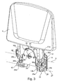
- die Fahrerstandplattform des Staplers der
Figur 1 in der eingeklappten Stellung für den Mitgängerbetrieb in einer perspektivischen Darstellung, - Figur 4
- einen Ausschnitt der
Figur 2 in einer vergrößertenFigur 5 Schnittdarstellung, die Fahrerstandplattform in einer Zwischenstellung und - Figur 6
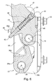
- einen Ausschnitt der
Figur 3 in einer vergrößerten Schnittdarstellung. - In der
Figur 1 ist ein erfindungsgemäßer Lagertechnikstapler 1, der beispielsweise als deichselgeführter Hubwagen, insbesondere Niederhubwagen, ausgebildet ist, dargestellt. Der Lagertechnikstapler 1 weist einen Antriebsteil 2 und einen relativ zu dem Antriebsteil 2 anhebbaren und absenkbaren Lastteil 3 auf. Der Lastteil 3 umfasst eine von beispielsweise zwei seitlich beabstandeten Lastarmen 4 gebildete Lastgabel. - Mittels an den Spitzen der Lastarme 4 angeordneten und nicht mehr dargestellter Lastrollen ist der Lastteil 3 auf einer Fahrbahn abgestützt.
- In dem Antriebsteil 2 ist eine nicht mehr dargestellte Fahrantriebseinheit, die ein Antriebsrad und einen das Antriebsrad antreibenden elektrischen Fahrantriebsmotor umfasst, um eine vertikale Schwenkachse lenkbar angeordnet ist. Das Lenken und die Bedienung des Lagertechnikstaplers 1 durch eine Bedienperson erfolgt mittels einer nicht mehr dargestellten Deichsel, die an der Oberseite des Antriebsteils 2 in dessen mittleren Bereich angeordnet ist.
- Der erfindungsgemäße Lagertechnikstapler 1 ist zum wahlweisen Betrieb im Mitgängerbetrieb und im Mitfahrerbetrieb vorgesehen. Hierzu ist an dem Antriebsteil 2 gegenüberliegend zu dem Lastteil 3 eine als Fahrerstandplattform ausgebildete Fahrerplattform 5 angeordnet, die um eine horizontale, in Fahrzeugquerrichtung angeordnete Schwenkachse 6 klappbar am Antriebsteil 2 angeordnet ist. In der
Figur 1 befindet sich die Fahrerplattform 5 in einer ausgeklappten Stellung für den Mitfahrerbetrieb des Lagertechnikstaplers 1. - Durch Hochschwenken um die Schwenkachse 6 kann die Fahrerplattform 5 in eine eingeklappte Stellung für den Mitgängerbetrieb des Lagertechnikstaplers 1 gebracht werden. In der Vorderseite des Antriebsteils 2 ist für die eingeklappte Fahrerplattform 5 eine Ausbuchtung vorhanden, so dass sich im Mitgängerbetrieb bei eingeklappter Fahrerplattform 5 die Fahrerplattform 5 innerhalb der Kontur des Antriebsteils 2 befindet.
- Erfindungsgemäß ist die Fahrerplattform 5 in der ausgeklappten Stellung für den Mitfahrerbetrieb mittels einer im Einstelldruck veränderbaren Luftfeder 10 am Fahrzeugrahmen abgestützt, um eine Federung und Dämpfung der Fahrerplattform 5 im Mitfahrerbetrieb des Lagertechnikstaplers 1 zu erzielen.
- In den
Figuren 2 bis 6 ist die Fahrerplattform 5 mit der Luftfeder 10 in einer konstruktiven Ausführungsform näher dargestellt. - Wie aus den
Figuren 2 und3 gezeigt ist, weist die als Fahrerstandplattform ausgebildete Fahrerplattform 5 zwei seitlich und in Fahrzeugquerrichtung beabstandete Schwenkträger 11a, 11b auf, die in einem Trägerbauteil 12 um die Schwenkachse 6 schwenkbar gelagert sind. Das Trägerbauteil 12 ist hierzu für jeden Schwenkträger 11a bzw. 11 b mit zwei vertikalen Flanschplatten 13a, 13b versehen, die einen Lagerflansch 13 bilden, zwischen denen der Schwenkträger 11a bzw. 11b angeordnet und mittels jeweils eines Lagerbolzens 14 schwenkbar gelagert sind. - Das Trägerbauteil 12 ist zwischen den seitlich beabstandeten Lagerflanschen 13 mit einer Aussparung versehen, in der die Luftfeder 10 angeordnet ist. Die Luftfeder 10 ist hierbei in horizontaler Richtung angeordnet und erstreckt sich in Fahrzeugslängsrichtung. Mittels Befestigungsschrauben 15 ist das Trägerbauteil 12 an einer entsprechenden vertikalen Rahmenplatte des Fahrzeugrahmens des Lagertechnikstaplers 1 lösbar befestigbar.
- Die Luftfeder 10 ist von einem Balgzylinder 20 gebildet, beispielsweise einem Einfaltenbalgzylinder, der zwischen zwei Anschlussplatten 21, 22 angeordnet ist. Mittels der Anschlussplatte 22 ist die Luftfeder 10 an der vertikalen Rahmenplatte des Fahrzeugrahmens des Lagertechnikstaplers 1 abgestützt. Mittels der Anschlussplatte 21 ist die Luftfeder an einer Andrückplatte 25 befestigt, beispielsweise mittels entsprechender Befestigungsschrauben 26. Die Andrückplatte 25 ist um eine horizontale, in Fahrzeugquerrichtung angeordnete Schwenkachse 27 an dem Trägerbauteil 12 schwenkbar gelagert. Die Schwenkachse 27 ist hierbei in vertikaler Richtung von der Schwenkachse 6 der Fahrerplattform 5 beabstandet.
- Die Andrückplatte 25 ist zur Lagerung an der Trägerplatte 12 im unteren Bereich mit seitlich beabstandeten Lagerflanschen 25a, 25b versehen. Die vertikalen Flanschplatten 13a, 13b des Trägerbauteils 12 bilden hierbei jeweils einen entsprechenden Lagerflansch 13, zwischen denen der Lagerflansch 25a bzw. 25b der Andrückplatte 25 angeordnet und mittels jeweils eines entsprechenden Lagerbolzens 28 schwenkbar gelagert ist.
- Zur Veränderung des Einstelldruckes der Luftfeder 10 ist der Balgzylinder 20 mit einem Ventil 30 versehen, beispielsweise einem üblichen Ventilanschlussstutzen. Die Andrückplatte 25 ist mit einer langlochförmigen Ausnehmung 32 versehen, durch die sich das Ventil 30 erstreckt. Wie in Verbindung mit der
Figur 1 ersichtlich ist, ist eine vordere vertikale Rahmenwand des Lagertechnikstaplers 1 ebenfalls mit einer nutförmigen Ausnehmung versehen, so dass sich das Ventil 30 am Antriebsteil 2 nach Außen erstreckt und von Außen zugänglich ist. - Zur Herstellung einer Wirkverbindung zwischen der Fahrerplattform 5 und der Andrückplatte 25 ist - wie in den
Figuren 4 bis 6 in Verbindung mit derFigur 3 ersichtlich ist - jeder Schwenkträger 11 a, 11 b der Fahrerplattform 5 mit einem von der Schwenkachse 6 beabstandeten Hebel 35a, 35b versehen. Der Hebel 35a, 35b ist hierbei von jeweils einer nockenförmigen Erweiterung des Schwenkträgers 11a, 11b gebildet und somit an dem Schwenkträger 11a, 11b angeformt. Die Anrückplatte 25 ist im Bereich der Lagerflansche 25a, 25b mit jeweils einer im Querschnitt V-förmigen und an die Hebel 35a, 35b angepasste Aufnahme 36a, 36b versehen, die von der Schwenkachse 27 beabstandet sind in der sich in der ausgeklappten Stellung der Fahrerplattform 5 - wie in derFigur 4 dargestellt ist - die Hebel 35a, 35b abstützen. - Die Aufnahmen 36a, 36b und die Hebel 35a, 35b sind hierbei in vertikaler Richtung zwischen den Schwenkachsen 6 und 27 angeordnet, so dass eine Belastung der Fahrerplattform 5 durch eine auf der Fahrerplattform 5 stehende Bedienperson und somit ein Verschwenken der Schwenkträger 11 a, 11 b um die Schwenkachse 6 entgegen dem Uhrzeigersinn zu einem Verschwenken der Andrückplatte 25 um die Schwenkachse 27 im Uhrzeigersinn führt, wodurch die Fahrerplattform 5 über die Luftfeder 10 am Fahrzeugrahmen gefedert abgestützt ist.
- In dem Schwenkträger 11a der Fahrerplattform 5 ist im Bereich des Hebels 35a eine Aufnahmebohrung 40 für eine Federeinrichtung 41 ausgebildet, die mit einem Betätigungsstößel 42 zusammenwirkt. Der Betätigungsstößel 42 erstreckt sich durch den Hebel 35a und steht mit einem aus dem Hebel 35a herauskragenden Ende mit der Aufnahme 36a der Andrückplatte 12 in Wirkverbindung. In der in der
Figur 4 dargestellten ausgeklappten Stellung der Fahrerplattform 5 wird die an einer Verschlussschraube 43 der Aufnahmebohrung 40 abgestützte Federeinrichtung 41 von dem an der Aufnahme 36a anliegenden Betätigungsstößel 42 vorgespannt. - Steigt eine Bedienperson von der Fahrerplattform 5, wird somit die Fahrerplattform 5 mittels der Federeinrichtung 41 und dem sich an der Aufnahme 36a der Andrückplatte 25 abstützenden Betätigungsstößel 42 in Richtung der eingeklappten Stellung hochgeklappt, bis der Betätigungsstößel 42 mit einem Anschlagbund an einem Bohrungsabsatz der Aufnahmebohrung 40 anliegt. In der
Figur 5 ist die Zwischenposition der Fahrerplattform 5 dargestellt. In Verbindung mit Sensoreinrichtungen 50, die die eingeklappte Stellung und die ausgeklappte Stellung der Fahrerplattform 5 ermitteln, kann mittels der Federeinrichtung 41 auf einfache Weise eine Totmannschaltung erzielt werden. - In der
Figur 6 ist die Fahrerplattform 5 in der eingeklappten Stellung dargestellt, in der die Hebel 35a, 35b außer Eingriff mit den Aufnahmen 36a, 36b der Andrückplatte 25 sind. An den Schwenkhebeln 11a bzw. 11 b sind Anschlagnasen 45 angeformt, mit denen die Schwenkhebel 11a, 11 b in der hochgeklappten Stellung der Fahrerplattform 5 an dem Trägerbauteil 12 anliegen. - Die Luftfeder 10 ist über das Ventil 30 und den entsprechenden Ventilanschlussstutzen auf einfache Weise im Einstelldruck veränderbar und anpassbar, so dass eine einfache Anpassung der Federung an das Gewicht der Bedienperson erzielt werden kann. Das Aufpumpen bzw. Luftablassen der Luftfeder 10 kann herbei über eine handbetätigte Luftpumpe erfolgen oder über eine in Fabrikhallen vorhandene stationäre Druckluftversorgung. Zudem ist möglich, in dem Lagertechnikstapler 1 einen Druckluftkompressor einzubauen, um eine interne Druckluftversorgung der Luftfeder 10 zu ermöglichen. Durch die Veränderung und Anpassung des Einstelldruckes der Luftfeder 10 ändert sich in axialer Richtung die Bauhöhe der Luftfeder, wobei über die Hebel 35a, 35b und die Aufnahmen 36a, 36b in der Andrückplatte 25 bei sich verändernder axialer Bauhöhe der Luftfeder 10 eine einfache Abstützung der Fahrerplattform 5 an der Luftfeder 10 erzielt werden kann.
- Durch die Abstützung der Fahrerplattform 5 mittels der an den Schwenkträgern 11a, 11 b angeordneten Hebeln 35a, 35b an der schwenkbaren Andrückplatte 25 kann hierbei eine platzsparende Bauweise in Fahrzeuglängsrichtung erzielt werden, bei der eine horizontale Anordnung der Luftfeder 10 in Fahrzeugslängsrichtung und eine Abstützung der Luftfeder 10 an einer vertikalen Rahmenplatte des Fahrzeugrahmens des Lagertechnikstaplers 1 erzielt werden kann.
- Zudem kann durch die Befestigung der Luftfeder 10 an der Andrückplatte 25, und der Lagerung der Fahrerplattform 5 sowie der Lagerung der Andrückplatte 25 an dem Trägerbauteil 12 eine einfach aufgebaute Baueinheit für die gefederte Fahrerplattform 5 gebildet werden, die auf einfache Weise an dem Lagertechnikstapler 1 über die Verschraubungen 15 befestigt werden kann, so dass ein Lagertechnikstapler 1 auf einfache Weise mit der gefederten Fahrerplattform 5 versehen werden kann.
Claims (15)
- Lagertechnikstapler, insbesondere Hubwagen, mit einer an einem Fahrzeugrahmen gefederten Fahrerplattform, insbesondere einer Fahrerstandplattform, dadurch gekennzeichnet, dass die Fahrerplattform (5) mittels einer im Einstelldruck veränderbaren Luftfeder (10) gefedert an dem Fahrzeugrahmen abgestützt ist.
- Lagertechnikstapler nach Anspruch 1, dadurch gekennzeichnet, dass die Luftfeder (10) als Balgzylinder (20), insbesondere als Einfaltenbalgzylinder, ausgebildet ist.
- Lagertechnikstapler nach Anspruch 1 oder 2, dadurch gekennzeichnet, dass die Luftfeder (10) mit einem Ventil (30) zum Anschluss an eine Luftpumpe oder eine stationäre Druckluftversorgung versehen ist.
- Lagertechnikstapler nach Anspruch 1 oder 2, dadurch gekennzeichnet, dass die Luftfeder (10) mit einem Druckluftkompressor des Lagertechnikstaplers (1) in Verbindung steht.
- Lagertechnikstapler nach einem der Ansprüche 1 bis 4, dadurch gekennzeichnet, dass die Fahrerplattform (5) um eine im wesentlichen horizontale Schwenkachse (6) schwenkbar gelagert ist, wobei die Fahrerplattform (5) mit mindestens einem Hebel (35a; 35b) versehen ist, der mit einer Andrückplatte (25) in Wirkverbindung bringbar ist, wobei die Andrückplatte (25) mit der Luftfeder (10) in Wirkverbindung steht.
- Lagertechnikstapler nach Anspruch 5, dadurch gekennzeichnet, dass die Andrückplatte (25) um eine im Wesentlichen horizontale Schwenkachse (27) schwenkbar gelagert ist.
- Lagertechnikstapler nach Anspruch 5 oder 6, dadurch gekennzeichnet, dass die Andrückplatte (25) mit mindestens einer Aufnahme (36a; 36b) für den Hebel (35a; 35b) versehen ist.
- Lagertechnikstapler nach einem der Ansprüche 5 bis 7, dadurch gekennzeichnet, dass die Fahrerplattform (5) mittels zwei seitlich beabstandeter Schwenkträgern (11a, 11 b) um die Schwenkachse (6) schwenkbar gelagert ist und die Andrückplatte (25) zwei seitlich beabstandete Aufnahmen (36a, 36b) für Hebel (35a, 35b) aufweist, wobei die Hebel (35a, 35b) an den Schwenkträgern (36a, 36b) ausgebildet sind und die Luftfeder (10) in seitlicher Richtung zwischen den Hebeln (35a, 35b) angeordnet ist.
- Lagertechnikstapler nach einem der Ansprüche 5 bis 8, dadurch gekennzeichnet, dass die Luftfeder (10) zwei Anschlussplatten (21, 22) mit einem dazwischen angeordneten Balgzylinder (20) umfasst, wobei die Luftfeder (10) mittels einer Anschlussplatte (21) an der Andrückplatte (25) befestigt ist und mittels der weiteren Anschlussplatte (22) an dem Fahrzeugrahmen abgestützt ist.
- Lagertechnikstapler nach einem der Ansprüche 5 bis 9, dadurch gekennzeichnet, dass die Andrückplatte (25) und die Fahrerplattform (5) an einem Trägerbauteil (12) schwenkbar befestigt sind, das an dem Fahrzeugrahmen des Lagertechnikfahrzeugs (1) lösbar befestigbar ist.
- Lagertechnikstapler nach Anspruch 10, dadurch gekennzeichnet, dass das Trägerbauteil (12) mit seitlich beabstandeten Lagerflanschen (13) für die Lagerung der Schwenkträger (11a, 11b) der Fahrerplattform (5) und für die Lagerung von Lagerflanschen (25a, 25b) der Andrückpatte (25) versehen ist, wobei das Trägerbauteil (12) zwischen den Lagerflanschen (13) mit einer Aussparung zur Aufnahme der Luftfeder (10) versehen ist.
- Lagertechnikstapler nach Anspruch 11, dadurch gekennzeichnet, dass die Aufnahmen (36a, 36b) für die Hebel (35a, 35b) an der Andrückplatte (25) im Bereich der Lagerflansche (25a, 25b) der Andrückplatte (25) angeordnet sind.
- Lagertechnikstapler nach einem der Ansprüche 6 bis 12, dadurch gekennzeichnet, dass die Schwenkachse (6) der Fahrerplattform (5) und die Schwenkachse (27) der Andrückplatte (25) in vertikaler Richtung beabstandet sind, wobei die Hebel (35a, 35b) und die Aufnahmen (36a, 36b) zwischen den Schwenkachsen (6, 27) angeordnet sind.
- Lagertechnikstapler nach einem der Ansprüche 5 bis 13, dadurch gekennzeichnet, dass an mindestens einem Hebel (35a; 35b) der Fahrerplattform (5) eine Federeinrichtung (41) angeordnet ist, die über einen Betätigungsstößel (42) mit der Aufnahme (36a; 36b) in Wirkverbindung bringbar ist, um eine Einklappbewegung der Fahrerplattform (5) zu unterstützen.
- Lagertechnikstapler nach einem der vorangegangenen Ansprüche, dadurch gekennzeichnet, dass der Lagertechnikstapler (1) zum wahlweisen Betrieb im Mitgängerbetrieb und Mitfahrerbetrieb ausgebildet ist und die Fahrerplattform (5) als klappbare Fahrerstandplattform (5) ausgebildet ist, die von einer eingeklappten Stellung im Mitgängerbetrieb in eine ausgeklappte Stellung im Mitfahrerbetrieb klappbar ist, wobei die Fahrerstandplattform (5) in der ausgeklappten Stellung für den Mitfahrerbetrieb mittels der Luftfeder (10) gefedert am Fahrzeugrahmen abgestützt ist.
Applications Claiming Priority (1)
| Application Number | Priority Date | Filing Date | Title |
|---|---|---|---|
| DE200910042318 DE102009042318A1 (de) | 2009-09-21 | 2009-09-21 | Lagertechnikstapler, insbesondere Hubwagen |
Publications (2)
| Publication Number | Publication Date |
|---|---|
| EP2301827A1 true EP2301827A1 (de) | 2011-03-30 |
| EP2301827B1 EP2301827B1 (de) | 2018-07-18 |
Family
ID=43244753
Family Applications (1)
| Application Number | Title | Priority Date | Filing Date |
|---|---|---|---|
| EP10009251.9A Active EP2301827B1 (de) | 2009-09-21 | 2010-09-06 | Lagertechnikstapler, insbesondere Hubwagen |
Country Status (2)
| Country | Link |
|---|---|
| EP (1) | EP2301827B1 (de) |
| DE (1) | DE102009042318A1 (de) |
Cited By (2)
| Publication number | Priority date | Publication date | Assignee | Title |
|---|---|---|---|---|
| CN105083398A (zh) * | 2014-05-19 | 2015-11-25 | 永恒力股份公司 | 随行地面运输工具 |
| US10858051B2 (en) | 2018-07-03 | 2020-12-08 | Mtd Products Inc | Standing platform and suspension assembly for riding equipment |
Families Citing this family (3)
| Publication number | Priority date | Publication date | Assignee | Title |
|---|---|---|---|---|
| DE102015120507A1 (de) | 2015-11-26 | 2017-06-01 | Still Gmbh | Lagertechnikstapler |
| DE102019101862A1 (de) * | 2019-01-25 | 2020-07-30 | Jungheinrich Aktiengesellschaft | Flurförderzeug mit Standplattform |
| EP3696134B1 (de) | 2019-02-13 | 2023-07-19 | STILL S.p.A. | Flurförderzeug mit einem eine fahrerstandplattform umfassenden fahrerarbeitsplatzmodul |
Citations (9)
| Publication number | Priority date | Publication date | Assignee | Title |
|---|---|---|---|---|
| EP0466065A1 (de) * | 1990-07-11 | 1992-01-15 | STEINBOCK BOSS GmbH | Lastförderfahrzeug |
| EP0449029B1 (de) | 1990-03-22 | 1994-05-25 | Linde Aktiengesellschaft | Deichselgeführtes elektrisches Flurförderzeug |
| JP2002145128A (ja) * | 2000-11-09 | 2002-05-22 | Nippon Yusoki Co Ltd | ローリフトトラック |
| DE10055263A1 (de) | 2000-11-08 | 2002-05-23 | Still & Saxby Sarl | Flurföderzeug mit einer elastisch abgestützten Standplattform |
| DE10159565A1 (de) | 2001-12-05 | 2003-06-18 | Linde Ag | Fahrerplatzmodul für einen Hubwagen |
| US20060103093A1 (en) * | 2004-09-10 | 2006-05-18 | Kallevig Bruce E | Rider platform for self-propelled vehicle |
| DE19601374B4 (de) | 1996-01-16 | 2007-02-22 | Linde Ag | Flurförderzeug mit einer Fahrer-Plattform |
| EP2014605A1 (de) * | 2007-07-09 | 2009-01-14 | BT Products AB | Lastenhebevorrichtung und Plattform für eine Lastenhebevorrichtung |
| EP2239187A1 (de) * | 2009-04-07 | 2010-10-13 | BT Products AB | System zur Erfassung der Position einer Drehplattform in einem Fahrzeug |
Family Cites Families (4)
| Publication number | Priority date | Publication date | Assignee | Title |
|---|---|---|---|---|
| US1404419A (en) * | 1917-07-13 | 1922-01-24 | Wright Hibbard Ind Electric Tr | Electrical industrial truck |
| DE10360298A1 (de) * | 2003-12-20 | 2005-07-14 | Still S.A.R.L. | Gefederte Fahrerplattform |
| DE102009058598B4 (de) * | 2009-12-17 | 2022-08-04 | Linde Material Handling Gmbh | Lagertechnikfahrzeug mit einer Fahrerstandplattform |
| DE102009058599B4 (de) * | 2009-12-17 | 2020-06-18 | Linde Material Handling Gmbh | Lagertechnikfahrzeug, insbesondere Hubwagen |
-
2009
- 2009-09-21 DE DE200910042318 patent/DE102009042318A1/de not_active Withdrawn
-
2010
- 2010-09-06 EP EP10009251.9A patent/EP2301827B1/de active Active
Patent Citations (9)
| Publication number | Priority date | Publication date | Assignee | Title |
|---|---|---|---|---|
| EP0449029B1 (de) | 1990-03-22 | 1994-05-25 | Linde Aktiengesellschaft | Deichselgeführtes elektrisches Flurförderzeug |
| EP0466065A1 (de) * | 1990-07-11 | 1992-01-15 | STEINBOCK BOSS GmbH | Lastförderfahrzeug |
| DE19601374B4 (de) | 1996-01-16 | 2007-02-22 | Linde Ag | Flurförderzeug mit einer Fahrer-Plattform |
| DE10055263A1 (de) | 2000-11-08 | 2002-05-23 | Still & Saxby Sarl | Flurföderzeug mit einer elastisch abgestützten Standplattform |
| JP2002145128A (ja) * | 2000-11-09 | 2002-05-22 | Nippon Yusoki Co Ltd | ローリフトトラック |
| DE10159565A1 (de) | 2001-12-05 | 2003-06-18 | Linde Ag | Fahrerplatzmodul für einen Hubwagen |
| US20060103093A1 (en) * | 2004-09-10 | 2006-05-18 | Kallevig Bruce E | Rider platform for self-propelled vehicle |
| EP2014605A1 (de) * | 2007-07-09 | 2009-01-14 | BT Products AB | Lastenhebevorrichtung und Plattform für eine Lastenhebevorrichtung |
| EP2239187A1 (de) * | 2009-04-07 | 2010-10-13 | BT Products AB | System zur Erfassung der Position einer Drehplattform in einem Fahrzeug |
Cited By (3)
| Publication number | Priority date | Publication date | Assignee | Title |
|---|---|---|---|---|
| CN105083398A (zh) * | 2014-05-19 | 2015-11-25 | 永恒力股份公司 | 随行地面运输工具 |
| CN105083398B (zh) * | 2014-05-19 | 2018-01-26 | 永恒力股份公司 | 随行地面运输工具 |
| US10858051B2 (en) | 2018-07-03 | 2020-12-08 | Mtd Products Inc | Standing platform and suspension assembly for riding equipment |
Also Published As
| Publication number | Publication date |
|---|---|
| EP2301827B1 (de) | 2018-07-18 |
| DE102009042318A1 (de) | 2011-03-24 |
Similar Documents
| Publication | Publication Date | Title |
|---|---|---|
| DE102009058598B4 (de) | Lagertechnikfahrzeug mit einer Fahrerstandplattform | |
| EP2301827B1 (de) | Lagertechnikstapler, insbesondere Hubwagen | |
| EP2311772A1 (de) | Flurförderzeug, insbesondere Hubwagen | |
| EP2861437A1 (de) | Radaufhängung | |
| EP3686151B1 (de) | Flurförderzeug mit standplattform | |
| EP2231463A1 (de) | Lenksäulenanordnung für kraftfahrzeuge | |
| EP3502039B1 (de) | Flurförderzeug mit einem eine fahrerstandplattform umfassenden fahrerarbeitsplatz | |
| EP3222491A1 (de) | Stützrolle eines flurförderzeugs | |
| DE102006009331A1 (de) | Standplattform mit einem Anwesenheitssensor | |
| DE60131805T2 (de) | Fahrzeugaufhängung mit zwei lenkbare Räder tragender Achse, insbesondere für Vierrad-Gabelstapler | |
| DE102009051275A1 (de) | Lagertechnikstapler, insbesondere Hubwagen | |
| EP3560801B1 (de) | Lagertechnikfahrzeug mit aktiver anpassung der einstiegshöhe | |
| EP3502041B1 (de) | Flurförderzeug mit einem eine fahrerstandplattform umfassenden fahrerarbeitsplatz | |
| DE102013100071A1 (de) | Flurförderzeug mit einer mittels einer Feder-Dämpfer-Einrichtung abgestützten Stützrolle | |
| WO2007033626A1 (de) | Federvorrichtung, insbesondere für einen fahrersitz | |
| EP3553019B1 (de) | Flurförderzeug mit einem eine fahrerstandplattform umfassenden fahrerarbeitsplatz | |
| DE102009058599B4 (de) | Lagertechnikfahrzeug, insbesondere Hubwagen | |
| DE102009057028A1 (de) | Verstelleinrichtung für eine Bedieneinrichtung eines Flurförderzeugs | |
| DE102010022762A1 (de) | Kraftfahrzeugachse mit Panhardstab | |
| DE102016119418B4 (de) | Flurförderzeug | |
| DE102014007884A1 (de) | Achshebevorrichtung | |
| EP4419059B1 (de) | Fahrzeug zum befahren einer treppe oder einer rampe | |
| DE102006004336B4 (de) | Niederhubwagen mit einer Hubeinrichtung | |
| DE102018112548A1 (de) | Flurförderzeug mit einem eine Fahrerstandplattform umfassenden Fahrerarbeitsplatz | |
| EP1591310B1 (de) | Kippeinrichtung für ein Fahrzeug |
Legal Events
| Date | Code | Title | Description |
|---|---|---|---|
| PUAI | Public reference made under article 153(3) epc to a published international application that has entered the european phase |
Free format text: ORIGINAL CODE: 0009012 |
|
| AK | Designated contracting states |
Kind code of ref document: A1 Designated state(s): AL AT BE BG CH CY CZ DE DK EE ES FI FR GB GR HR HU IE IS IT LI LT LU LV MC MK MT NL NO PL PT RO SE SI SK SM TR |
|
| AX | Request for extension of the european patent |
Extension state: BA ME RS |
|
| 17P | Request for examination filed |
Effective date: 20110929 |
|
| RAP1 | Party data changed (applicant data changed or rights of an application transferred) |
Owner name: OM CARRELLI ELEVATORI S.P.A. |
|
| 17Q | First examination report despatched |
Effective date: 20150515 |
|
| GRAP | Despatch of communication of intention to grant a patent |
Free format text: ORIGINAL CODE: EPIDOSNIGR1 |
|
| STAA | Information on the status of an ep patent application or granted ep patent |
Free format text: STATUS: GRANT OF PATENT IS INTENDED |
|
| INTG | Intention to grant announced |
Effective date: 20180214 |
|
| GRAS | Grant fee paid |
Free format text: ORIGINAL CODE: EPIDOSNIGR3 |
|
| GRAA | (expected) grant |
Free format text: ORIGINAL CODE: 0009210 |
|
| STAA | Information on the status of an ep patent application or granted ep patent |
Free format text: STATUS: THE PATENT HAS BEEN GRANTED |
|
| AK | Designated contracting states |
Kind code of ref document: B1 Designated state(s): AL AT BE BG CH CY CZ DE DK EE ES FI FR GB GR HR HU IE IS IT LI LT LU LV MC MK MT NL NO PL PT RO SE SI SK SM TR |
|
| REG | Reference to a national code |
Ref country code: GB Ref legal event code: FG4D Free format text: NOT ENGLISH |
|
| REG | Reference to a national code |
Ref country code: CH Ref legal event code: EP |
|
| REG | Reference to a national code |
Ref country code: IE Ref legal event code: FG4D Free format text: LANGUAGE OF EP DOCUMENT: GERMAN |
|
| REG | Reference to a national code |
Ref country code: DE Ref legal event code: R096 Ref document number: 502010015157 Country of ref document: DE |
|
| REG | Reference to a national code |
Ref country code: AT Ref legal event code: REF Ref document number: 1019027 Country of ref document: AT Kind code of ref document: T Effective date: 20180815 |
|
| REG | Reference to a national code |
Ref country code: FR Ref legal event code: PLFP Year of fee payment: 9 |
|
| REG | Reference to a national code |
Ref country code: SE Ref legal event code: TRGR |
|
| REG | Reference to a national code |
Ref country code: NL Ref legal event code: MP Effective date: 20180718 |
|
| REG | Reference to a national code |
Ref country code: LT Ref legal event code: MG4D |
|
| PG25 | Lapsed in a contracting state [announced via postgrant information from national office to epo] |
Ref country code: NL Free format text: LAPSE BECAUSE OF FAILURE TO SUBMIT A TRANSLATION OF THE DESCRIPTION OR TO PAY THE FEE WITHIN THE PRESCRIBED TIME-LIMIT Effective date: 20180718 |
|
| PG25 | Lapsed in a contracting state [announced via postgrant information from national office to epo] |
Ref country code: GR Free format text: LAPSE BECAUSE OF FAILURE TO SUBMIT A TRANSLATION OF THE DESCRIPTION OR TO PAY THE FEE WITHIN THE PRESCRIBED TIME-LIMIT Effective date: 20181019 Ref country code: BG Free format text: LAPSE BECAUSE OF FAILURE TO SUBMIT A TRANSLATION OF THE DESCRIPTION OR TO PAY THE FEE WITHIN THE PRESCRIBED TIME-LIMIT Effective date: 20181018 Ref country code: NO Free format text: LAPSE BECAUSE OF FAILURE TO SUBMIT A TRANSLATION OF THE DESCRIPTION OR TO PAY THE FEE WITHIN THE PRESCRIBED TIME-LIMIT Effective date: 20181018 Ref country code: LT Free format text: LAPSE BECAUSE OF FAILURE TO SUBMIT A TRANSLATION OF THE DESCRIPTION OR TO PAY THE FEE WITHIN THE PRESCRIBED TIME-LIMIT Effective date: 20180718 Ref country code: PL Free format text: LAPSE BECAUSE OF FAILURE TO SUBMIT A TRANSLATION OF THE DESCRIPTION OR TO PAY THE FEE WITHIN THE PRESCRIBED TIME-LIMIT Effective date: 20180718 Ref country code: IS Free format text: LAPSE BECAUSE OF FAILURE TO SUBMIT A TRANSLATION OF THE DESCRIPTION OR TO PAY THE FEE WITHIN THE PRESCRIBED TIME-LIMIT Effective date: 20181118 Ref country code: FI Free format text: LAPSE BECAUSE OF FAILURE TO SUBMIT A TRANSLATION OF THE DESCRIPTION OR TO PAY THE FEE WITHIN THE PRESCRIBED TIME-LIMIT Effective date: 20180718 |
|
| PG25 | Lapsed in a contracting state [announced via postgrant information from national office to epo] |
Ref country code: AL Free format text: LAPSE BECAUSE OF FAILURE TO SUBMIT A TRANSLATION OF THE DESCRIPTION OR TO PAY THE FEE WITHIN THE PRESCRIBED TIME-LIMIT Effective date: 20180718 Ref country code: HR Free format text: LAPSE BECAUSE OF FAILURE TO SUBMIT A TRANSLATION OF THE DESCRIPTION OR TO PAY THE FEE WITHIN THE PRESCRIBED TIME-LIMIT Effective date: 20180718 Ref country code: LV Free format text: LAPSE BECAUSE OF FAILURE TO SUBMIT A TRANSLATION OF THE DESCRIPTION OR TO PAY THE FEE WITHIN THE PRESCRIBED TIME-LIMIT Effective date: 20180718 Ref country code: ES Free format text: LAPSE BECAUSE OF FAILURE TO SUBMIT A TRANSLATION OF THE DESCRIPTION OR TO PAY THE FEE WITHIN THE PRESCRIBED TIME-LIMIT Effective date: 20180718 |
|
| REG | Reference to a national code |
Ref country code: DE Ref legal event code: R097 Ref document number: 502010015157 Country of ref document: DE |
|
| PG25 | Lapsed in a contracting state [announced via postgrant information from national office to epo] |
Ref country code: MC Free format text: LAPSE BECAUSE OF FAILURE TO SUBMIT A TRANSLATION OF THE DESCRIPTION OR TO PAY THE FEE WITHIN THE PRESCRIBED TIME-LIMIT Effective date: 20180718 Ref country code: IT Free format text: LAPSE BECAUSE OF FAILURE TO SUBMIT A TRANSLATION OF THE DESCRIPTION OR TO PAY THE FEE WITHIN THE PRESCRIBED TIME-LIMIT Effective date: 20180718 Ref country code: RO Free format text: LAPSE BECAUSE OF FAILURE TO SUBMIT A TRANSLATION OF THE DESCRIPTION OR TO PAY THE FEE WITHIN THE PRESCRIBED TIME-LIMIT Effective date: 20180718 Ref country code: CZ Free format text: LAPSE BECAUSE OF FAILURE TO SUBMIT A TRANSLATION OF THE DESCRIPTION OR TO PAY THE FEE WITHIN THE PRESCRIBED TIME-LIMIT Effective date: 20180718 Ref country code: EE Free format text: LAPSE BECAUSE OF FAILURE TO SUBMIT A TRANSLATION OF THE DESCRIPTION OR TO PAY THE FEE WITHIN THE PRESCRIBED TIME-LIMIT Effective date: 20180718 |
|
| REG | Reference to a national code |
Ref country code: CH Ref legal event code: PL |
|
| PLBE | No opposition filed within time limit |
Free format text: ORIGINAL CODE: 0009261 |
|
| STAA | Information on the status of an ep patent application or granted ep patent |
Free format text: STATUS: NO OPPOSITION FILED WITHIN TIME LIMIT |
|
| PG25 | Lapsed in a contracting state [announced via postgrant information from national office to epo] |
Ref country code: SM Free format text: LAPSE BECAUSE OF FAILURE TO SUBMIT A TRANSLATION OF THE DESCRIPTION OR TO PAY THE FEE WITHIN THE PRESCRIBED TIME-LIMIT Effective date: 20180718 Ref country code: DK Free format text: LAPSE BECAUSE OF FAILURE TO SUBMIT A TRANSLATION OF THE DESCRIPTION OR TO PAY THE FEE WITHIN THE PRESCRIBED TIME-LIMIT Effective date: 20180718 Ref country code: SK Free format text: LAPSE BECAUSE OF FAILURE TO SUBMIT A TRANSLATION OF THE DESCRIPTION OR TO PAY THE FEE WITHIN THE PRESCRIBED TIME-LIMIT Effective date: 20180718 |
|
| REG | Reference to a national code |
Ref country code: BE Ref legal event code: MM Effective date: 20180930 |
|
| 26N | No opposition filed |
Effective date: 20190423 |
|
| GBPC | Gb: european patent ceased through non-payment of renewal fee |
Effective date: 20181018 |
|
| REG | Reference to a national code |
Ref country code: IE Ref legal event code: MM4A |
|
| PG25 | Lapsed in a contracting state [announced via postgrant information from national office to epo] |
Ref country code: LU Free format text: LAPSE BECAUSE OF NON-PAYMENT OF DUE FEES Effective date: 20180906 |
|
| REG | Reference to a national code |
Ref country code: DE Ref legal event code: R082 Ref document number: 502010015157 Country of ref document: DE Representative=s name: PATENTSHIP PATENTANWALTSGESELLSCHAFT MBH, DE Ref country code: DE Ref legal event code: R081 Ref document number: 502010015157 Country of ref document: DE Owner name: STILL S.P.A., IT Free format text: FORMER OWNER: OM CARRELLI ELEVATORI S.P.A., LAINATE, MILANO, IT |
|
| PG25 | Lapsed in a contracting state [announced via postgrant information from national office to epo] |
Ref country code: IE Free format text: LAPSE BECAUSE OF NON-PAYMENT OF DUE FEES Effective date: 20180906 |
|
| PG25 | Lapsed in a contracting state [announced via postgrant information from national office to epo] |
Ref country code: SI Free format text: LAPSE BECAUSE OF FAILURE TO SUBMIT A TRANSLATION OF THE DESCRIPTION OR TO PAY THE FEE WITHIN THE PRESCRIBED TIME-LIMIT Effective date: 20180718 Ref country code: LI Free format text: LAPSE BECAUSE OF NON-PAYMENT OF DUE FEES Effective date: 20180930 Ref country code: CH Free format text: LAPSE BECAUSE OF NON-PAYMENT OF DUE FEES Effective date: 20180930 Ref country code: BE Free format text: LAPSE BECAUSE OF NON-PAYMENT OF DUE FEES Effective date: 20180930 |
|
| PG25 | Lapsed in a contracting state [announced via postgrant information from national office to epo] |
Ref country code: GB Free format text: LAPSE BECAUSE OF NON-PAYMENT OF DUE FEES Effective date: 20181018 |
|
| REG | Reference to a national code |
Ref country code: AT Ref legal event code: MM01 Ref document number: 1019027 Country of ref document: AT Kind code of ref document: T Effective date: 20180906 |
|
| PG25 | Lapsed in a contracting state [announced via postgrant information from national office to epo] |
Ref country code: MT Free format text: LAPSE BECAUSE OF FAILURE TO SUBMIT A TRANSLATION OF THE DESCRIPTION OR TO PAY THE FEE WITHIN THE PRESCRIBED TIME-LIMIT Effective date: 20180718 Ref country code: AT Free format text: LAPSE BECAUSE OF NON-PAYMENT OF DUE FEES Effective date: 20180906 |
|
| PG25 | Lapsed in a contracting state [announced via postgrant information from national office to epo] |
Ref country code: TR Free format text: LAPSE BECAUSE OF FAILURE TO SUBMIT A TRANSLATION OF THE DESCRIPTION OR TO PAY THE FEE WITHIN THE PRESCRIBED TIME-LIMIT Effective date: 20180718 |
|
| PG25 | Lapsed in a contracting state [announced via postgrant information from national office to epo] |
Ref country code: HU Free format text: LAPSE BECAUSE OF FAILURE TO SUBMIT A TRANSLATION OF THE DESCRIPTION OR TO PAY THE FEE WITHIN THE PRESCRIBED TIME-LIMIT; INVALID AB INITIO Effective date: 20100906 Ref country code: PT Free format text: LAPSE BECAUSE OF FAILURE TO SUBMIT A TRANSLATION OF THE DESCRIPTION OR TO PAY THE FEE WITHIN THE PRESCRIBED TIME-LIMIT Effective date: 20180718 |
|
| PG25 | Lapsed in a contracting state [announced via postgrant information from national office to epo] |
Ref country code: MK Free format text: LAPSE BECAUSE OF NON-PAYMENT OF DUE FEES Effective date: 20180718 Ref country code: CY Free format text: LAPSE BECAUSE OF FAILURE TO SUBMIT A TRANSLATION OF THE DESCRIPTION OR TO PAY THE FEE WITHIN THE PRESCRIBED TIME-LIMIT Effective date: 20180718 |
|
| P01 | Opt-out of the competence of the unified patent court (upc) registered |
Effective date: 20230510 |
|
| PGFP | Annual fee paid to national office [announced via postgrant information from national office to epo] |
Ref country code: DE Payment date: 20250919 Year of fee payment: 16 |
|
| PGFP | Annual fee paid to national office [announced via postgrant information from national office to epo] |
Ref country code: FR Payment date: 20250922 Year of fee payment: 16 |
|
| PGFP | Annual fee paid to national office [announced via postgrant information from national office to epo] |
Ref country code: SE Payment date: 20250922 Year of fee payment: 16 |