EP2302149A1 - Dispositif d'actionnement, par exemple cylindre de fermeture ou garniture de poignée de porte, doté d'un organe de commutation pouvant se rabattre magnétiquement par un élément de commutation - Google Patents
Dispositif d'actionnement, par exemple cylindre de fermeture ou garniture de poignée de porte, doté d'un organe de commutation pouvant se rabattre magnétiquement par un élément de commutation Download PDFInfo
- Publication number
- EP2302149A1 EP2302149A1 EP10180528A EP10180528A EP2302149A1 EP 2302149 A1 EP2302149 A1 EP 2302149A1 EP 10180528 A EP10180528 A EP 10180528A EP 10180528 A EP10180528 A EP 10180528A EP 2302149 A1 EP2302149 A1 EP 2302149A1
- Authority
- EP
- European Patent Office
- Prior art keywords
- magnet
- drive
- actuating device
- coupling
- switching
- Prior art date
- Legal status (The legal status is an assumption and is not a legal conclusion. Google has not performed a legal analysis and makes no representation as to the accuracy of the status listed.)
- Granted
Links
- 230000008878 coupling Effects 0.000 claims description 106
- 238000010168 coupling process Methods 0.000 claims description 106
- 238000005859 coupling reaction Methods 0.000 claims description 106
- 230000000903 blocking effect Effects 0.000 claims description 17
- 230000033001 locomotion Effects 0.000 claims description 12
- 238000006073 displacement reaction Methods 0.000 claims description 10
- 230000005540 biological transmission Effects 0.000 claims description 4
- 230000000694 effects Effects 0.000 description 10
- 230000006835 compression Effects 0.000 description 8
- 238000007906 compression Methods 0.000 description 8
- 238000007654 immersion Methods 0.000 description 7
- 210000004072 lung Anatomy 0.000 description 4
- 230000003993 interaction Effects 0.000 description 2
- 230000001846 repelling effect Effects 0.000 description 2
- 208000012886 Vertigo Diseases 0.000 description 1
- 230000001419 dependent effect Effects 0.000 description 1
- 238000007598 dipping method Methods 0.000 description 1
- 210000003746 feather Anatomy 0.000 description 1
- 230000005764 inhibitory process Effects 0.000 description 1
- 230000007935 neutral effect Effects 0.000 description 1
- 230000000717 retained effect Effects 0.000 description 1
Images









Classifications
-
- E—FIXED CONSTRUCTIONS
- E05—LOCKS; KEYS; WINDOW OR DOOR FITTINGS; SAFES
- E05B—LOCKS; ACCESSORIES THEREFOR; HANDCUFFS
- E05B47/00—Operating or controlling locks or other fastening devices by electric or magnetic means
- E05B47/06—Controlling mechanically-operated bolts by electro-magnetically-operated detents
- E05B47/0611—Cylinder locks with electromagnetic control
- E05B47/0638—Cylinder locks with electromagnetic control by disconnecting the rotor
- E05B47/0646—Cylinder locks with electromagnetic control by disconnecting the rotor radially
- E05B47/0649—Cylinder locks with electromagnetic control by disconnecting the rotor radially with a rectilinearly moveable coupling element
-
- E—FIXED CONSTRUCTIONS
- E05—LOCKS; KEYS; WINDOW OR DOOR FITTINGS; SAFES
- E05B—LOCKS; ACCESSORIES THEREFOR; HANDCUFFS
- E05B47/00—Operating or controlling locks or other fastening devices by electric or magnetic means
- E05B47/0038—Operating or controlling locks or other fastening devices by electric or magnetic means using permanent magnets
-
- E—FIXED CONSTRUCTIONS
- E05—LOCKS; KEYS; WINDOW OR DOOR FITTINGS; SAFES
- E05B—LOCKS; ACCESSORIES THEREFOR; HANDCUFFS
- E05B47/00—Operating or controlling locks or other fastening devices by electric or magnetic means
- E05B47/06—Controlling mechanically-operated bolts by electro-magnetically-operated detents
- E05B47/0611—Cylinder locks with electromagnetic control
- E05B47/0615—Cylinder locks with electromagnetic control operated by handles, e.g. by knobs
-
- E—FIXED CONSTRUCTIONS
- E05—LOCKS; KEYS; WINDOW OR DOOR FITTINGS; SAFES
- E05B—LOCKS; ACCESSORIES THEREFOR; HANDCUFFS
- E05B47/00—Operating or controlling locks or other fastening devices by electric or magnetic means
- E05B47/06—Controlling mechanically-operated bolts by electro-magnetically-operated detents
- E05B47/0657—Controlling mechanically-operated bolts by electro-magnetically-operated detents by locking the handle, spindle, follower or the like
- E05B47/0661—Controlling mechanically-operated bolts by electro-magnetically-operated detents by locking the handle, spindle, follower or the like axially, i.e. with an axially engaging blocking element
-
- E—FIXED CONSTRUCTIONS
- E05—LOCKS; KEYS; WINDOW OR DOOR FITTINGS; SAFES
- E05B—LOCKS; ACCESSORIES THEREFOR; HANDCUFFS
- E05B47/00—Operating or controlling locks or other fastening devices by electric or magnetic means
- E05B47/06—Controlling mechanically-operated bolts by electro-magnetically-operated detents
- E05B47/0676—Controlling mechanically-operated bolts by electro-magnetically-operated detents by disconnecting the handle
- E05B47/0684—Controlling mechanically-operated bolts by electro-magnetically-operated detents by disconnecting the handle radially
- E05B47/0692—Controlling mechanically-operated bolts by electro-magnetically-operated detents by disconnecting the handle radially with a rectilinearly moveable coupling element
-
- E—FIXED CONSTRUCTIONS
- E05—LOCKS; KEYS; WINDOW OR DOOR FITTINGS; SAFES
- E05B—LOCKS; ACCESSORIES THEREFOR; HANDCUFFS
- E05B47/00—Operating or controlling locks or other fastening devices by electric or magnetic means
- E05B47/0001—Operating or controlling locks or other fastening devices by electric or magnetic means with electric actuators; Constructional features thereof
- E05B2047/0014—Constructional features of actuators or power transmissions therefor
- E05B2047/0015—Output elements of actuators
- E05B2047/0017—Output elements of actuators with rotary motion
-
- E—FIXED CONSTRUCTIONS
- E05—LOCKS; KEYS; WINDOW OR DOOR FITTINGS; SAFES
- E05B—LOCKS; ACCESSORIES THEREFOR; HANDCUFFS
- E05B47/00—Operating or controlling locks or other fastening devices by electric or magnetic means
- E05B47/0001—Operating or controlling locks or other fastening devices by electric or magnetic means with electric actuators; Constructional features thereof
- E05B2047/0014—Constructional features of actuators or power transmissions therefor
- E05B2047/0018—Details of actuator transmissions
- E05B2047/002—Geared transmissions
-
- E—FIXED CONSTRUCTIONS
- E05—LOCKS; KEYS; WINDOW OR DOOR FITTINGS; SAFES
- E05B—LOCKS; ACCESSORIES THEREFOR; HANDCUFFS
- E05B47/00—Operating or controlling locks or other fastening devices by electric or magnetic means
- E05B47/0001—Operating or controlling locks or other fastening devices by electric or magnetic means with electric actuators; Constructional features thereof
- E05B2047/0014—Constructional features of actuators or power transmissions therefor
- E05B2047/0018—Details of actuator transmissions
- E05B2047/0026—Clutches, couplings or braking arrangements
- E05B2047/003—Clutches, couplings or braking arrangements of the overload- slip- or friction type
-
- E—FIXED CONSTRUCTIONS
- E05—LOCKS; KEYS; WINDOW OR DOOR FITTINGS; SAFES
- E05B—LOCKS; ACCESSORIES THEREFOR; HANDCUFFS
- E05B47/00—Operating or controlling locks or other fastening devices by electric or magnetic means
- E05B47/0001—Operating or controlling locks or other fastening devices by electric or magnetic means with electric actuators; Constructional features thereof
- E05B2047/0014—Constructional features of actuators or power transmissions therefor
- E05B2047/0018—Details of actuator transmissions
- E05B2047/0026—Clutches, couplings or braking arrangements
- E05B2047/0031—Clutches, couplings or braking arrangements of the elastic type
-
- E—FIXED CONSTRUCTIONS
- E05—LOCKS; KEYS; WINDOW OR DOOR FITTINGS; SAFES
- E05B—LOCKS; ACCESSORIES THEREFOR; HANDCUFFS
- E05B47/00—Operating or controlling locks or other fastening devices by electric or magnetic means
- E05B2047/0092—Operating or controlling locks or other fastening devices by electric or magnetic means including means for preventing manipulation by an external magnetic field, e.g. preventing opening by using a strong magnet
-
- E—FIXED CONSTRUCTIONS
- E05—LOCKS; KEYS; WINDOW OR DOOR FITTINGS; SAFES
- E05B—LOCKS; ACCESSORIES THEREFOR; HANDCUFFS
- E05B47/00—Operating or controlling locks or other fastening devices by electric or magnetic means
- E05B47/0001—Operating or controlling locks or other fastening devices by electric or magnetic means with electric actuators; Constructional features thereof
- E05B47/0012—Operating or controlling locks or other fastening devices by electric or magnetic means with electric actuators; Constructional features thereof with rotary electromotors
Definitions
- the invention relates to an actuating device with a drive part mounted in a housing and a movable by actuation of the drive member in an operative position of a switching member driven part, wherein the switching member by magnetic force during displacement of a switching element associated first magnet between the operative position and a counteracting position back and forth is movable, in which Schmidt sued a movement of the driven part is prevented by pressing the drive member.
- An actuator in the form of a lock cylinder describes the DE 103 03 220 A2 ,
- the lock cylinder has a drive shaft which carries a knob at each end.
- the drive shaft is rotatably mounted in a housing of the lock cylinder.
- a closing member which can be coupled to the drive shaft by means of a coupling member.
- a slide having a magnet can be brought into a positive connection between the closing member and the drive shaft.
- a permanent magnet which can be displaced in the axial direction of the drive shaft.
- a second magnet opposed thereto drives the coupling slider to the uncoupled position. While in the coupling position, the closing member is rotated at a rotation of the knob, it is not rotated in the uncoupled position or only with a small Mitschleppkraft.
- the invention has for its object to improve such an operating device functionally.
- a second magnet adjacent to the first magnet is proposed.
- This magnet is polarized in opposite directions to the first magnet.
- a compensation magnetic field is built up, with which external magnetic fields can be compensated.
- External magnetic fields may otherwise be able to affect the switching function of the switching magnet formed by the first magnet.
- Both magnets can be displaced by a common drive device. This is preferably done by turning both magnets.
- the two magnets are firmly connected. The two magnets are spaced apart, in such a way that the field constructed by the second magnet does not affect the panel constructed by the first magnet. Relative to the axis of rotation of the drive shaft, the two magnets have an axial distance.
- the two magnets are firmly seated on a common magnetic carrier.
- This magnetic carrier may be a rotary armature or the axis of rotation of a drive motor. But it is also possible to shift the position of the two magnets in the axial direction for switching. It can even be provided that one of the two magnets exerts a switching function.
- either the first or the second magnet is brought between two oppositely poled drive magnets.
- These permanent magnets are associated with the switching element, which is formed in particular by a slider. The other magnet then forms a compensation magnet.
- the switching element can cooperate with coupling members.
- the switching element can also exercise a blocking function.
- the actuator may be a lock cylinder with a rotatably mounted in the housing of the lock cylinder closing member which forms the actuator.
- the lock cylinder may have a drive shaft provided with a knob, which is switchable by means of a displaceable by the first magnet by magnetic force switching element between a rotatable uncoupled position and a rotationally fixed coupling position to the closing member.
- the uncoupled position is the counteracting position and the coupling position is the active position.
- It may be provided a coupling member, which is acted upon by the force of a spring in a coupling recess, from which it can escape in the decoupled position and in which it is held in the coupling position by the switching member.
- the second magnet is adjacent to the first magnet and opposite polarity to the first magnet. Both magnets can be shifted from the same drive unit.
- the coupling members are acted upon by a spring in coupling recesses. In the decoupled position, they can emerge from the coupling recesses, so that the torques transmitted to the closing member with the drive shaft are small and insufficient to close a lock with the closing member. In the coupling position, the coupling members are held positively by a slide. In the coupling position, the coupling members can not escape from the coupling recesses, so that in this position a rotationally fixed entrainment of the closing member is ensured by the drive shaft.
- the magnetic actuator has in the axial direction of the drive shaft rotatable, poled in the radial direction switching magnet, which cooperates with two opposite polarity, diametrically to the axis of rotation of the switching magnet associated with the slider permanent magnet.
- the switching magnet can be turned against two stops.
- the switching magnet changes its direction of force with respect to the slider when it is rotated by 180 °.
- In an initial position of the switching magnet is in the immediate vicinity of a poled in the same direction permanent magnet of the slider.
- the slider is thus held either in the uncoupled or in the coupled position.
- the coupling members can escape in immersion clearances of the slide. This is done in the radial direction, based on the axis of rotation of the drive shaft.
- the switching magnet is rotated by a drive motor. It is preferably pivoted by more than 180 °, for example by 220 °. In a 180 ° rotation are opposite poles, so that the switching magnet unfolds a repulsive effect on the permanent magnet lying next to him and also on the magnet lying away him an attractive effect. Since the switching magnet is rotated when switching but beyond the 180 ° -Winkel ein out in a Verkipplage, it is held by the stronger repulsive force in the Verkipplage against a stop.
- the freely displaceable with inoperative lock cylinder slide shifts due to the changed direction of force in the other operating position, in turn, the switching magnet is in attractive operative connection to the nearest him permanent magnet of the slide. This changes the position of the switching magnet. It pivots out of the Verkipplage, so that its pole axis is in the direction of the polar axis of the permanent magnet.
- the coupling recesses are preferably formed by V-shaped radial recesses of a ring inner wall of the closing member.
- a plurality of preferably eight coupling recesses are arranged in a uniform circumferential distribution about the axis of rotation of the closing member. In each case two mutually opposite coupling recesses obliquely cut tips of the coupling members are substantially a positive fit.
- the two ends of the coupling members facing away from the locking tips are acted upon by a spreading spring, so that the two coupling members are acted upon by a common helical gear compression spring in the coupling recesses.
- Between the two mutually facing ends of the coupling members of the coupling slide is displaceable in the radial direction to the axis of rotation.
- the switching magnet sits on a drive shaft of an electric motor, which is located in the drive shaft of the lock cylinder.
- the electric motor is preferably supported by two housing halves in the drive shaft. One of the two housing halves can form the stop against which a counter-stop of the drive shaft of the electric motor or the switching magnet occurs when the latter is rotated.
- the switching member is preferably formed by a rotary body which is rotatable by a drive motor between two end positions.
- the drive can be coaxial. But it is also possible that the drive axis of the drive motor is parallel to the axis of rotation of the switching element.
- the transmission of motion from the drive motor to the switching element can take place via a lower or a transmission gear, for example a gearwheel.
- the displacement of the switching element causes a rotational blockade of the drive member.
- the drive part may have a blocking recess into which a switching element formed by a slide is inserted in the counteracting position.
- the switching element may have the form of a round pin which is non-rotatably but axially displaceable inserted in a bearing cavity.
- the front side of this pin carries oppositely poled drive magnet.
- the two magnets of the switching member are oppositely poled next to each other, wherein the pole axes may extend in the axial direction of the axis of rotation of the switching member.
- the two magnets each face a drive magnet, with which the first magnet interacts either via a repelling or an attractive interaction.
- the actuator is preferably designed as a lock cylinder, wherein the switching member and the switching member are housed as well as the drive motor in the profile section of the cylinder housing.
- the switching member shifts between active position and counteracting position in the direction of the axis of rotation of the switching element, which extends transversely to the axis of rotation of the closing member of the lock cylinder whose rotation is blocked or released by displacing the switching element.
- a development of the invention relates to the embodiment of the actuator as a nut coupling.
- Such a nut coupling may be provided in a door fitting plate.
- the nut clutch has two nut halves which are rotationally engageable via suitable coupling means, one of which has a nut of a door lock and the other is connected to a door handle. If the two nut halves are held in a coupling position, the nut of the lock and thus the latch of the lock can be withdrawn by actuating the door handle.
- a decoupled position takes place when turning the handle handle no rotational drive of the other half of the nut.
- the two nut halves are coupled together via a mutual tooth engagement, which is maintained in the coupling position by means of a coupling rocker.
- the coupling rocker is held by a switching element according to the invention in the coupling position. If the switching element is displaced from this active position into a counteracting position, the coupling rocker can deflect, so that the two nut halves get out of meshing engagement.
- the switching element preferably has two oppositely poled drive magnet.
- the switching member has a first magnet which performs the switching function and whose polar direction can be changed by turning the switching member.
- a second magnet is arranged, which unfolds the initially described compensation effect.
- the first and second magnets together generate a quadrupole field.
- the magnetic fields built up by the two essentially equally strong magnets thus compensate each other outside the actuating device.
- An external magnetic field, in particular an external magnetic dipole field, is hardly capable of disturbing or compensating the magnetic force of the first magnet acting on the at least one drive magnet such that the switching element is moved back and forth between the active position and the counteracting position without displacement of the switching element ,
- An inventively designed actuator in the form of a lock cylinder may have two drive shafts.
- a drive shaft connected to a door-side knob can be permanently coupled to the closing member in a rotationally fixed manner.
- a second, with a door outside Rotary knob coupled drive shaft can be coupled via the coupling described above with the closing member. But it is also possible that both drive shafts can transmit torque in the coupled position on the closing member. It is considered to be particularly advantageous that all electrical lines run within the drive shaft or the rotary knob fixedly connected to the drive shaft. No safety-relevant electrical cables need to be led out of the cylinder body or out of the knob. Furthermore, it is considered advantageous that the electric motor or the switching magnet can be rotated in any operating position. There are no mechanical elements that could block the rotatability of the engine.
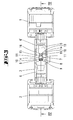
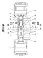
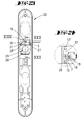
- the in the FIGS. 1 to 18 Lock cylinder shown is a double lock cylinder.
- a knob 1, 2 is provided on each side of the double lock cylinder.
- the knob 1 is fixedly connected to a drive shaft 6 '
- the knob 2 is fixedly connected to a drive shaft 6.
- the two drive shafts 6, 6 ' are mounted in bearing bores of a cylinder housing 3.
- a recess is provided in which a closing member 4 is mounted rotatably. With the closing member 4, a mortise lock of a door can be actuated.
- the drive shaft 6 'with the closing member 4 can be brought into different operative positions. In a coupling position torques can be transmitted via the drive shaft 6 'on the closing member. In a decoupled position, only small torques can be transmitted from the drive shaft 6 'to the closing member 4.
- a drive motor 5 is mounted in the drive shaft 6 '.
- two housing halves 16 which receive the motor 5.
- electrical lines of the motor 5 is connected to a control electronics, which is located in the knob 1.
- the control electronics may be connected to a transceiver to communicate with a transponder carrying a privacy secret.
- the drive motor 5 drives a motor drive shaft, on which a stopper body 14 is seated.
- This stopper body 14 cooperates with a counter-stop 15, so that the motor shaft of the electric motor 5 can only rotate by a limited angle of rotation.
- the angle of rotation is greater than 180 °, but less than 360 ° and is approximately in the range between 220 ° and 270 °.
- a switching magnet 7 On the end of the motor shaft of the electric motor 5 is a switching magnet 7.
- the axis of rotation of the motor shaft 19 extends coaxially to the drive shaft 6 '.
- the polarity of the switching magnet 7 is directed in the radial direction.
- Fig. 5 can be seen, is located on the motor shaft 19, a further magnet 18.
- the further magnet 18 is from the switching magnet 7 relative to the axis of rotation of the electric motor 5 in the axial direction of the switching magnet 7 spaced. How the particular Fig. 7 can be seen, switching magnet 7 and the magnet 18 are polarized in opposite directions.
- the polar axes are parallel to each other in the radial direction, but with opposite polarity.
- the second magnet 18 forms a compensation magnet to prevent interference by external magnetic fields.
- the switching magnet 7 is seated in an oval recess 17 of a slider 8.
- the slider 8 is mounted in the radial direction with respect to the axis of rotation of the drive shaft 6 'displaceable in the region of the closing member 4.
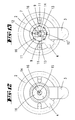
- the slider 8 has two permanent magnets 12, 12 ', which are connected in opposite polarity in diametrical opposite position relative to the switching magnet 7 fixed to the slider 8. If the polar direction of the switching magnet 7 lies in the direction of the pole axis of the two permanent magnets 12, 12 ', the switching magnet 7 is in detracting operative connection with one of the permanent magnets 12 in attractive operative connection and with the respective other permanent magnet 12'. This has the consequence that the freely displaceable in the interior of the closing member 4 slider 8 moves to a position in which the attracting magnet 12 is the Umschaltmagneten 7 closest.
- the associated with the slider 8 magnets 12 are in the same axial plane in which the switching magnet 7 is located.
- the axial plane in which the compensation magnet 18 is located is offset in the axial direction relative to the radial plane in which the permanent magnets 12 lie.
- the switching magnet 7 If the switching magnet 7 is rotated by 180 °, the permanent magnet 12 closest to the switching magnet 7 at the moment develops a repulsive effect. However, since the switching magnet is rotated by more than 180 ° to a stop position, it is (initially) acted upon against the stop due to the repulsive effect. The repulsive effect on the nearest permanent magnet 12 and the then attractive effect on the removed lying permanent magnet 12 'but then leads to a relocation of the slider. 8
- the two previously discussed displacement positions of the slide 8 are each assigned an operating position. In a first displacement position, the slide can assume the decoupled operating position, in the second displacement position, the coupling position.
- the slide has two opposite transverse to the pole axis of the permanent magnets 12, 12 'aligned immersion clearances 13. Relative to the middle between the two permanent magnets 12, 12' are the two immersion free spaces 13 one of the two permanent magnets 12 'adjacent.
- the coupling members 9 Transverse to the direction of displacement of the permanent magnet and also in the radial direction with respect to the axis of rotation of the drive shaft 6, 6 'are located within the closing member 4, two coupling members 9.
- the coupling members 9 have tapered coupling tips 9', which point away from each other.
- the coupling tips 9 ' have sloping edges.
- the coupling tips 9 ' normally stuck in each coupling recesses 11, wherein the two diametrically opposite tips 9' in diametrically opposite coupling recesses 11 eino.
- the closure member 4 has an annular portion.
- In the inner wall of the ring are substantially V-shaped coupling recesses 11.
- the two coupling members 9 have locking ends 9 "which are spaced apart from each other, and the distance between the two locking ends 9" in the normal operating position is greater than the width of the slider 8.
- a distance between the two Locking 9 "of the two coupling members 9 extending compression spring 10 acts on the coupling members 9 in the coupling recesses eleventh
- the coupling member 8 If the coupling member 8 is in the decoupled position, the two immersion clearances 13 are aligned with the blocking ends 9 "of the coupling members 9. If the drive shaft 6 'is rotated in this state, the closing member 4 is first dragged along 4 but to a resistance, the bevelled tips 9 'of the coupling members 9 slide on the inclined flanks of the coupling recesses 11, so that the coupling members 9 displace in the radial direction immerse yourself in the immersion free spaces 13 and overflow the lying between the coupling recesses 11 coupling projections of the closing member 4. It is thus a free rotation in the uncoupled position of the drive shaft 6 'guaranteed. The tips 9 ', that is, the oblique flanks of the coupling members 9, thereby emerge completely from the coupling recesses 11.
- the two magnets 7, 18 each form a switching magnet.
- the relevant embodiment differs from the embodiment shown in the drawings only essentially in that the motor 5 does not rotationally drive the magnet carrier 18, but linearly displaces it.
- the slider 8 may for this purpose have an opening through which the magnetic carrier 19 can be pushed.
- the magnet carrier 19 is then moved back and forth in the axial direction relative to the cylinder axis of rotation, so that either the first magnet 7 or the second magnet 18 polarized opposite thereto is located between the oppositely poled drive magnets 12.
- the slider shifted in one direction or the other from either the magnet 7 or the magnet 18.
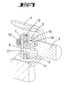
- FIGS. 19 to 21 illustrated second embodiment also relates to a lock cylinder with a cylinder housing 3.
- a drive shaft 6 is connected to a cylinder core, which can be rotated by inserting a matching key into a keyway.
- the coupling between the drive shaft 6 and a blocking collar 21 can take place via a slip clutch.
- the coaxial with the drive shaft 6 arranged in the housing 3 blocking collar 21 is rotatably connected to a driven part, which is formed by a closing member 4, connected, so that in an operative position of a switching element 3, in the Fig. 20 is shown, the rotation of the key is transmitted to the closing member 4. In this operative position, the front end of the switching member 23 is outside a blocking recess 22 which is associated with the outer wall of the blocking collar 21.
- an electric motor 5 which is connected in motion via a first gear 24 and a second gear 25 with a switching member 19.
- the axis of rotation of the electric motor 5 runs parallel to the axis of rotation of the switching element 19. Both axes of rotation extend transversely to the axis of rotation of the drive shaft 6.
- a bearing cavity in which the freely movable switching member 23 is mounted which is formed by a slider.
- the front side of this slider 23, which faces the end face of the switching element 19, is equipped with two polarized magnets 12, 12 'in opposite directions. The polar direction of these two drive magnets 12, 12 'extends in the direction of movement of the switching member 23rd
- the switching member 23 is rotatably mounted, but axially displaceable in the bearing cavity.
- Each of the two drive magnets 12, 12 ' is a magnet 7, 18 of the switching element 19 opposite, wherein the polarity of the two magnets. 7 , 18 in the opposite direction but parallel to the axis of rotation of the switching element 19.
- the magnets 7, 18; 12, 12 ' arranged such that the magnets 7, 12' and 18, 12 attract each other. Since both magnet pairs are oppositely poled, they develop a compensating effect to shield external magnetic fields. They each generate a magnetic quadrupole field. The field lines are closed in a very small ambient volume of the four quadrupole magnets arranged.
- the switching member 19 If the switching member 19 is rotated by 180 °, which takes place by energizing the electric motor 5, then the drive magnets 12, 12 'are respectively counter-magnetized magnets 7, 18. While in the in Fig. 20 shown active position the switching member 19 exerts an attraction force on the switching member 23, the switching member 19 exercises in the in Fig. 21 illustrated Gegenwirk ein a repulsive force on the switching element 23 from. Escapes the blocking recess 22 with the switching member 23, the switching member 23 enters the blocking recess 22, so that the blocking collar 21 and thus also the closing member 4 can not be rotated. Again, proves the presence of a compensation magnet 18 in the immediate vicinity of the first magnet 7 as conducive. Because of the opposite polarity of the Compensation magnet 18 to the first switching magnet 7 is given a high level of security.
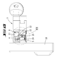
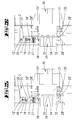
- first Nussteil 29 with a square opening into which a square mandrel is inserted, with which the nut 29 can be coupled with a nut of a mortise lock a door.
- the first Nussteil 29 is connected to a second Nussteil 30, which has a square pin for attaching a door handle, via a toothed engagement 33, 34.
- the tooth engagement is formed by teeth 33 extending in the axial direction of the two nut parts 29, 30.
- the teeth 33 engage in tooth gaps 34, wherein both the tooth spaces 34 and the teeth 33 have circumferentially extending bevels.
- the Nussteil 29 has a radially projecting collar 29 ', on which a coupling rocker 28 is supported. One end 28 'of the coupling rocker 28 is supported on a closure plate 32. The second end 28 "of the coupling rocker 28 cooperates with a switching element 26, which is designed as a slide, and a compression spring 27 is provided which holds the axially displaceable socket part 29 in the coupling position via a pressure on the coupling rocker 28.
- the Nussteil 30 By means of a leg spring 31, the Nussteil 30 will be held in a middle neutral position, from which it can be rotated by turning the pusher.
- the switching member 26 is formed as a slide and can by means of a magnetic force of a in Fig. 25 shown operative position in which a locking projection 26 'in the trajectory of the end 28 "of the coupling rocker 28 is located in an in Fig. 26 shown counteracting position are brought in the the end 28 "of the coupling rocker 28 can escape 27 against the restoring force of the compression spring.
- the adjustment of the switching element 26 is effected by means of a switching member 19.
- the switching member 19 is rotated by an electric motor 5, as in the previous embodiments, between two stop positions by 180 °.
- the switching member 19 carries a first magnet 7, which forms a switching magnet.
- the switching member 19 carries a compensation magnet 18 which, based on the first magnet 7, has an opposite polar direction.
- both magnets 7, 18 are equally strong within the tolerances, so that the magnetic fields generated by them in the distance substantially cancel each other out.
- the switching magnet 7 thus lies between one of two drive magnets 12, 12 'defined axis.
- the switching member 19 has a rotational position in which the first magnet 7 is in attractive interaction with the drive magnet 12 '.
- the other drive magnet 12 is repelled by the first magnet 7.
- the end 28 "of the coupling rocker 28 lies underneath the blocking shoulder 26 'of the closing member 26 and can not yield, as a result of which the toothed engagement 33, 34 is retained even when a torque is applied by the nut part 30 to the nut part 29.
Landscapes
- Physics & Mathematics (AREA)
- Electromagnetism (AREA)
- Lock And Its Accessories (AREA)
Applications Claiming Priority (1)
| Application Number | Priority Date | Filing Date | Title |
|---|---|---|---|
| DE102009043358A DE102009043358A1 (de) | 2008-04-11 | 2009-09-29 | Schließzylinder mit magnetisch gekuppeltem Schließglied |
Publications (2)
| Publication Number | Publication Date |
|---|---|
| EP2302149A1 true EP2302149A1 (fr) | 2011-03-30 |
| EP2302149B1 EP2302149B1 (fr) | 2014-10-29 |
Family
ID=43509223
Family Applications (1)
| Application Number | Title | Priority Date | Filing Date |
|---|---|---|---|
| EP20100180528 Not-in-force EP2302149B1 (fr) | 2009-09-29 | 2010-09-28 | Dispositif d'actionnement, par exemple cylindre de fermeture ou garniture de poignée de porte, doté d'un organe de commutation pouvant se rabattre magnétiquement par un élément de commutation |
Country Status (3)
| Country | Link |
|---|---|
| EP (1) | EP2302149B1 (fr) |
| DE (2) | DE102009043358A1 (fr) |
| ES (1) | ES2522974T3 (fr) |
Cited By (8)
| Publication number | Priority date | Publication date | Assignee | Title |
|---|---|---|---|---|
| EP2466043A1 (fr) * | 2010-12-20 | 2012-06-20 | Microhard S.R.L. | Dispositif de couplage d'une poignée externe à un verrou |
| DE102014104607B3 (de) * | 2014-04-01 | 2015-09-17 | Dom Sicherheitstechnik Gmbh & Co Kg | Elektromechanische Kupplungsanordnung mit magnetischem Drehschalter und Verfahren |
| EP2848754A3 (fr) * | 2013-09-11 | 2016-04-13 | Aug. Winkhaus GmbH & Co. KG | Barillet de serrure |
| GB2546552A (en) * | 2016-01-25 | 2017-07-26 | Ramtech Electronics Ltd | A handle control unit |
| DE102016210779A1 (de) * | 2016-06-16 | 2017-12-21 | Geze Gmbh | Türbeschlag |
| EP3480396A1 (fr) * | 2017-11-02 | 2019-05-08 | iLOQ Oy | Serrure électromécanique utilisant des forces de champ magnétique |
| CN112900977A (zh) * | 2021-02-01 | 2021-06-04 | 珠海磐磊智能科技有限公司 | 锁体、锁具及智能锁 |
| CN114833849A (zh) * | 2022-06-06 | 2022-08-02 | 深圳市尚为照明有限公司 | 一种防爆机器人 |
Families Citing this family (2)
| Publication number | Priority date | Publication date | Assignee | Title |
|---|---|---|---|---|
| DE102011113796A1 (de) * | 2011-09-12 | 2013-03-14 | Assa Abloy Sicherheitstechnik Gmbh | Knaufzylinder |
| DE102014111413B3 (de) | 2014-08-11 | 2015-09-17 | ASTRA Gesellschaft für Asset Management mbH & Co. KG | Schließzylinderanordnung |
Citations (7)
| Publication number | Priority date | Publication date | Assignee | Title |
|---|---|---|---|---|
| CH478323A (de) * | 1966-08-05 | 1969-09-15 | Huwil Werke Gmbh | Schliesszylinder mit magnetbetätigten Kuppelstücken |
| EP0999328A1 (fr) * | 1998-11-05 | 2000-05-10 | Simons & Voss Identifikationssysteme GmbH | Serrure cylindrique |
| DE10065155A1 (de) * | 2000-12-23 | 2002-06-27 | Schulte Zylinderschl Gmbh | Kupplungsanordnung in einem Schließzylinder |
| DE10359620A1 (de) * | 2002-12-20 | 2004-07-01 | Vachette | Sicherheitsschloss mit mechanischer und elektrischer Verriegelung |
| DE10303220B3 (de) | 2003-01-23 | 2004-09-16 | Dom Sicherheitstechnik Gmbh & Co Kg | Schließzylinder |
| DE102007000439A1 (de) * | 2007-08-13 | 2009-02-19 | Aug. Winkhaus Gmbh & Co. Kg | Elektronisch betätigter Schließzylinder |
| EP2083137A1 (fr) * | 2008-01-28 | 2009-07-29 | EZ Trend Technology Co., Ltd. | Verrou électrique |
Family Cites Families (2)
| Publication number | Priority date | Publication date | Assignee | Title |
|---|---|---|---|---|
| FR1591129A (fr) * | 1968-10-17 | 1970-04-27 | ||
| JP4295542B2 (ja) * | 2003-04-08 | 2009-07-15 | 美和ロック株式会社 | 防犯サムターン |
-
2009
- 2009-09-29 DE DE102009043358A patent/DE102009043358A1/de not_active Ceased
-
2010
- 2010-09-28 DE DE202010017885U patent/DE202010017885U1/de not_active Expired - Lifetime
- 2010-09-28 EP EP20100180528 patent/EP2302149B1/fr not_active Not-in-force
- 2010-09-28 ES ES10180528.1T patent/ES2522974T3/es active Active
Patent Citations (7)
| Publication number | Priority date | Publication date | Assignee | Title |
|---|---|---|---|---|
| CH478323A (de) * | 1966-08-05 | 1969-09-15 | Huwil Werke Gmbh | Schliesszylinder mit magnetbetätigten Kuppelstücken |
| EP0999328A1 (fr) * | 1998-11-05 | 2000-05-10 | Simons & Voss Identifikationssysteme GmbH | Serrure cylindrique |
| DE10065155A1 (de) * | 2000-12-23 | 2002-06-27 | Schulte Zylinderschl Gmbh | Kupplungsanordnung in einem Schließzylinder |
| DE10359620A1 (de) * | 2002-12-20 | 2004-07-01 | Vachette | Sicherheitsschloss mit mechanischer und elektrischer Verriegelung |
| DE10303220B3 (de) | 2003-01-23 | 2004-09-16 | Dom Sicherheitstechnik Gmbh & Co Kg | Schließzylinder |
| DE102007000439A1 (de) * | 2007-08-13 | 2009-02-19 | Aug. Winkhaus Gmbh & Co. Kg | Elektronisch betätigter Schließzylinder |
| EP2083137A1 (fr) * | 2008-01-28 | 2009-07-29 | EZ Trend Technology Co., Ltd. | Verrou électrique |
Cited By (20)
| Publication number | Priority date | Publication date | Assignee | Title |
|---|---|---|---|---|
| ITMI20102326A1 (it) * | 2010-12-20 | 2012-06-21 | Microhard Srl | Dispositivo di accoppiamento della maniglia esterna ad una serratura |
| EP2466043A1 (fr) * | 2010-12-20 | 2012-06-20 | Microhard S.R.L. | Dispositif de couplage d'une poignée externe à un verrou |
| EP2848754A3 (fr) * | 2013-09-11 | 2016-04-13 | Aug. Winkhaus GmbH & Co. KG | Barillet de serrure |
| DE102014104607B3 (de) * | 2014-04-01 | 2015-09-17 | Dom Sicherheitstechnik Gmbh & Co Kg | Elektromechanische Kupplungsanordnung mit magnetischem Drehschalter und Verfahren |
| EP2930292A1 (fr) | 2014-04-01 | 2015-10-14 | DOM Sicherheitstechnik GmbH & Co. KG | Système de couplage électromécanique doté d'un commutateur rotatif magnétique et procédé |
| GB2546552A (en) * | 2016-01-25 | 2017-07-26 | Ramtech Electronics Ltd | A handle control unit |
| DE102016210779B4 (de) | 2016-06-16 | 2019-12-24 | Geze Gmbh | Türbeschlag mit einer Kupplung |
| DE102016210779A1 (de) * | 2016-06-16 | 2017-12-21 | Geze Gmbh | Türbeschlag |
| CN111279040A (zh) * | 2017-11-02 | 2020-06-12 | 伊洛克公司 | 利用磁场力的电动机械锁 |
| WO2019086587A1 (fr) | 2017-11-02 | 2019-05-09 | Iloq Oy | Serrure électromagnétique utilisant des forces de champ magnétique |
| EP3480396A1 (fr) * | 2017-11-02 | 2019-05-08 | iLOQ Oy | Serrure électromécanique utilisant des forces de champ magnétique |
| US20200291683A1 (en) * | 2017-11-02 | 2020-09-17 | Iloq Oy | Electromechanical lock utilizing magnetic field forces |
| JP2021501840A (ja) * | 2017-11-02 | 2021-01-21 | イロク オサケ ユキチュア | 磁界力を利用する電気機械式ロック |
| RU2749442C1 (ru) * | 2017-11-02 | 2021-06-10 | Айлок Ой | Электромеханический замок с использованием сил магнитного поля |
| CN111279040B (zh) * | 2017-11-02 | 2021-08-13 | 伊洛克公司 | 利用磁场力的电动机械锁 |
| US11808057B2 (en) | 2017-11-02 | 2023-11-07 | Iloq Oy | Electromechanical lock utilizing magnetic field forces |
| CN112900977A (zh) * | 2021-02-01 | 2021-06-04 | 珠海磐磊智能科技有限公司 | 锁体、锁具及智能锁 |
| CN112900977B (zh) * | 2021-02-01 | 2022-07-05 | 珠海磐磊智能科技有限公司 | 锁体、锁具及智能锁 |
| CN114833849A (zh) * | 2022-06-06 | 2022-08-02 | 深圳市尚为照明有限公司 | 一种防爆机器人 |
| CN114833849B (zh) * | 2022-06-06 | 2024-01-16 | 深圳市尚为照明有限公司 | 一种防爆机器人 |
Also Published As
| Publication number | Publication date |
|---|---|
| DE202010017885U1 (de) | 2012-12-12 |
| ES2522974T3 (es) | 2014-11-19 |
| DE102009043358A1 (de) | 2011-04-07 |
| EP2302149B1 (fr) | 2014-10-29 |
Similar Documents
| Publication | Publication Date | Title |
|---|---|---|
| EP2302149B1 (fr) | Dispositif d'actionnement, par exemple cylindre de fermeture ou garniture de poignée de porte, doté d'un organe de commutation pouvant se rabattre magnétiquement par un élément de commutation | |
| EP1608830B1 (fr) | Dispositif de fermeture magneto-mecanique | |
| DE3617217C2 (fr) | ||
| EP3058154B1 (fr) | Poignée de porte | |
| EP2336628B1 (fr) | Verrouillage de fermeture | |
| EP3207197B1 (fr) | Élément d'actionnement pour une serrure à palastre | |
| EP2436858B1 (fr) | Cylindre de fermeture pour un verrou | |
| DE2711061C2 (de) | Permanentmagnet-Schlüssel betätigbares Schloß | |
| DE10303220B3 (de) | Schließzylinder | |
| DE3632904C2 (fr) | ||
| DE19939717A1 (de) | Handbetätigungsvorrichtung mit Drehgriff für elektrische Schaltgeräte | |
| EP1576246A1 (fr) | Dispositif de verrouillage | |
| CH701790A2 (de) | Schliesseinrichtung. | |
| DE102008018297A1 (de) | Schließzylinder mit magnetisch gekuppeltem Schließglied | |
| EP1719861B1 (fr) | Serrure cylindrique pour un système de verrouillage électronique | |
| DE102007011554B4 (de) | Koppeleinheit für elektronische Schließ-Systeme | |
| DE102014119252A1 (de) | Betätigungsvorrichtung für einen Verriegelungsmechanismus einer Tür oder eines Fensters | |
| DE102013104366B4 (de) | Kupplung für ein elektromechanisches Schloss | |
| DE112007002578B4 (de) | Schließzylinder | |
| DE102015007872B3 (de) | Koppelsystem für elektronische Schließsysteme | |
| EP1722049A2 (fr) | Système de verrouillage électromécanique | |
| DE102012020450A1 (de) | Kupplungsmechanismus für ein Türbetätigungsteil | |
| EP1931843B1 (fr) | Dispositif de verrouillage | |
| EP4112856B1 (fr) | Serrure dotée d'un verrou pouvant tourner à l'aide d'un élément d'actionnement | |
| DE102011000576A1 (de) | Schloss für eine Tür oder Dergleichen sowie Handwerkzeug für ein Schloss |
Legal Events
| Date | Code | Title | Description |
|---|---|---|---|
| PUAI | Public reference made under article 153(3) epc to a published international application that has entered the european phase |
Free format text: ORIGINAL CODE: 0009012 |
|
| AK | Designated contracting states |
Kind code of ref document: A1 Designated state(s): AL AT BE BG CH CY CZ DE DK EE ES FI FR GB GR HR HU IE IS IT LI LT LU LV MC MK MT NL NO PL PT RO SE SI SK SM TR |
|
| AX | Request for extension of the european patent |
Extension state: BA ME RS |
|
| 17P | Request for examination filed |
Effective date: 20110518 |
|
| 17Q | First examination report despatched |
Effective date: 20121015 |
|
| GRAP | Despatch of communication of intention to grant a patent |
Free format text: ORIGINAL CODE: EPIDOSNIGR1 |
|
| INTG | Intention to grant announced |
Effective date: 20140415 |
|
| GRAS | Grant fee paid |
Free format text: ORIGINAL CODE: EPIDOSNIGR3 |
|
| GRAA | (expected) grant |
Free format text: ORIGINAL CODE: 0009210 |
|
| AK | Designated contracting states |
Kind code of ref document: B1 Designated state(s): AL AT BE BG CH CY CZ DE DK EE ES FI FR GB GR HR HU IE IS IT LI LT LU LV MC MK MT NL NO PL PT RO SE SI SK SM TR |
|
| REG | Reference to a national code |
Ref country code: GB Ref legal event code: FG4D Free format text: NOT ENGLISH |
|
| REG | Reference to a national code |
Ref country code: CH Ref legal event code: EP Ref country code: CH Ref legal event code: NV Representative=s name: R. A. EGLI AND CO. PATENTANWAELTE, CH |
|
| REG | Reference to a national code |
Ref country code: AT Ref legal event code: REF Ref document number: 693703 Country of ref document: AT Kind code of ref document: T Effective date: 20141115 |
|
| REG | Reference to a national code |
Ref country code: IE Ref legal event code: FG4D Free format text: LANGUAGE OF EP DOCUMENT: GERMAN Ref country code: ES Ref legal event code: FG2A Ref document number: 2522974 Country of ref document: ES Kind code of ref document: T3 Effective date: 20141119 |
|
| REG | Reference to a national code |
Ref country code: DE Ref legal event code: R096 Ref document number: 502010008134 Country of ref document: DE Effective date: 20141204 |
|
| REG | Reference to a national code |
Ref country code: RO Ref legal event code: EPE |
|
| REG | Reference to a national code |
Ref country code: NL Ref legal event code: T3 |
|
| REG | Reference to a national code |
Ref country code: LT Ref legal event code: MG4D |
|
| PG25 | Lapsed in a contracting state [announced via postgrant information from national office to epo] |
Ref country code: FI Free format text: LAPSE BECAUSE OF FAILURE TO SUBMIT A TRANSLATION OF THE DESCRIPTION OR TO PAY THE FEE WITHIN THE PRESCRIBED TIME-LIMIT Effective date: 20141029 Ref country code: IS Free format text: LAPSE BECAUSE OF FAILURE TO SUBMIT A TRANSLATION OF THE DESCRIPTION OR TO PAY THE FEE WITHIN THE PRESCRIBED TIME-LIMIT Effective date: 20150228 Ref country code: NO Free format text: LAPSE BECAUSE OF FAILURE TO SUBMIT A TRANSLATION OF THE DESCRIPTION OR TO PAY THE FEE WITHIN THE PRESCRIBED TIME-LIMIT Effective date: 20150129 Ref country code: PT Free format text: LAPSE BECAUSE OF FAILURE TO SUBMIT A TRANSLATION OF THE DESCRIPTION OR TO PAY THE FEE WITHIN THE PRESCRIBED TIME-LIMIT Effective date: 20150302 Ref country code: LT Free format text: LAPSE BECAUSE OF FAILURE TO SUBMIT A TRANSLATION OF THE DESCRIPTION OR TO PAY THE FEE WITHIN THE PRESCRIBED TIME-LIMIT Effective date: 20141029 |
|
| PG25 | Lapsed in a contracting state [announced via postgrant information from national office to epo] |
Ref country code: HR Free format text: LAPSE BECAUSE OF FAILURE TO SUBMIT A TRANSLATION OF THE DESCRIPTION OR TO PAY THE FEE WITHIN THE PRESCRIBED TIME-LIMIT Effective date: 20141029 Ref country code: PL Free format text: LAPSE BECAUSE OF FAILURE TO SUBMIT A TRANSLATION OF THE DESCRIPTION OR TO PAY THE FEE WITHIN THE PRESCRIBED TIME-LIMIT Effective date: 20141029 Ref country code: LV Free format text: LAPSE BECAUSE OF FAILURE TO SUBMIT A TRANSLATION OF THE DESCRIPTION OR TO PAY THE FEE WITHIN THE PRESCRIBED TIME-LIMIT Effective date: 20141029 Ref country code: GR Free format text: LAPSE BECAUSE OF FAILURE TO SUBMIT A TRANSLATION OF THE DESCRIPTION OR TO PAY THE FEE WITHIN THE PRESCRIBED TIME-LIMIT Effective date: 20150130 Ref country code: SE Free format text: LAPSE BECAUSE OF FAILURE TO SUBMIT A TRANSLATION OF THE DESCRIPTION OR TO PAY THE FEE WITHIN THE PRESCRIBED TIME-LIMIT Effective date: 20141029 Ref country code: CY Free format text: LAPSE BECAUSE OF FAILURE TO SUBMIT A TRANSLATION OF THE DESCRIPTION OR TO PAY THE FEE WITHIN THE PRESCRIBED TIME-LIMIT Effective date: 20141029 |
|
| REG | Reference to a national code |
Ref country code: DE Ref legal event code: R097 Ref document number: 502010008134 Country of ref document: DE |
|
| PG25 | Lapsed in a contracting state [announced via postgrant information from national office to epo] |
Ref country code: EE Free format text: LAPSE BECAUSE OF FAILURE TO SUBMIT A TRANSLATION OF THE DESCRIPTION OR TO PAY THE FEE WITHIN THE PRESCRIBED TIME-LIMIT Effective date: 20141029 Ref country code: DK Free format text: LAPSE BECAUSE OF FAILURE TO SUBMIT A TRANSLATION OF THE DESCRIPTION OR TO PAY THE FEE WITHIN THE PRESCRIBED TIME-LIMIT Effective date: 20141029 Ref country code: SK Free format text: LAPSE BECAUSE OF FAILURE TO SUBMIT A TRANSLATION OF THE DESCRIPTION OR TO PAY THE FEE WITHIN THE PRESCRIBED TIME-LIMIT Effective date: 20141029 |
|
| PLBE | No opposition filed within time limit |
Free format text: ORIGINAL CODE: 0009261 |
|
| STAA | Information on the status of an ep patent application or granted ep patent |
Free format text: STATUS: NO OPPOSITION FILED WITHIN TIME LIMIT |
|
| 26N | No opposition filed |
Effective date: 20150730 |
|
| PG25 | Lapsed in a contracting state [announced via postgrant information from national office to epo] |
Ref country code: SI Free format text: LAPSE BECAUSE OF FAILURE TO SUBMIT A TRANSLATION OF THE DESCRIPTION OR TO PAY THE FEE WITHIN THE PRESCRIBED TIME-LIMIT Effective date: 20141029 |
|
| PG25 | Lapsed in a contracting state [announced via postgrant information from national office to epo] |
Ref country code: MC Free format text: LAPSE BECAUSE OF FAILURE TO SUBMIT A TRANSLATION OF THE DESCRIPTION OR TO PAY THE FEE WITHIN THE PRESCRIBED TIME-LIMIT Effective date: 20141029 Ref country code: LU Free format text: LAPSE BECAUSE OF FAILURE TO SUBMIT A TRANSLATION OF THE DESCRIPTION OR TO PAY THE FEE WITHIN THE PRESCRIBED TIME-LIMIT Effective date: 20150928 |
|
| REG | Reference to a national code |
Ref country code: IE Ref legal event code: MM4A |
|
| PG25 | Lapsed in a contracting state [announced via postgrant information from national office to epo] |
Ref country code: IE Free format text: LAPSE BECAUSE OF NON-PAYMENT OF DUE FEES Effective date: 20150928 |
|
| REG | Reference to a national code |
Ref country code: FR Ref legal event code: PLFP Year of fee payment: 7 |
|
| PG25 | Lapsed in a contracting state [announced via postgrant information from national office to epo] |
Ref country code: MT Free format text: LAPSE BECAUSE OF FAILURE TO SUBMIT A TRANSLATION OF THE DESCRIPTION OR TO PAY THE FEE WITHIN THE PRESCRIBED TIME-LIMIT Effective date: 20141029 |
|
| PG25 | Lapsed in a contracting state [announced via postgrant information from national office to epo] |
Ref country code: BG Free format text: LAPSE BECAUSE OF FAILURE TO SUBMIT A TRANSLATION OF THE DESCRIPTION OR TO PAY THE FEE WITHIN THE PRESCRIBED TIME-LIMIT Effective date: 20141029 Ref country code: HU Free format text: LAPSE BECAUSE OF FAILURE TO SUBMIT A TRANSLATION OF THE DESCRIPTION OR TO PAY THE FEE WITHIN THE PRESCRIBED TIME-LIMIT; INVALID AB INITIO Effective date: 20100928 Ref country code: SM Free format text: LAPSE BECAUSE OF FAILURE TO SUBMIT A TRANSLATION OF THE DESCRIPTION OR TO PAY THE FEE WITHIN THE PRESCRIBED TIME-LIMIT Effective date: 20141029 |
|
| PG25 | Lapsed in a contracting state [announced via postgrant information from national office to epo] |
Ref country code: BE Free format text: LAPSE BECAUSE OF NON-PAYMENT OF DUE FEES Effective date: 20150930 |
|
| PG25 | Lapsed in a contracting state [announced via postgrant information from national office to epo] |
Ref country code: TR Free format text: LAPSE BECAUSE OF FAILURE TO SUBMIT A TRANSLATION OF THE DESCRIPTION OR TO PAY THE FEE WITHIN THE PRESCRIBED TIME-LIMIT Effective date: 20141029 |
|
| REG | Reference to a national code |
Ref country code: FR Ref legal event code: PLFP Year of fee payment: 8 |
|
| REG | Reference to a national code |
Ref country code: DE Ref legal event code: R082 Ref document number: 502010008134 Country of ref document: DE Representative=s name: RIEDER & PARTNER MBB PATENTANWAELTE - RECHTSAN, DE Ref country code: DE Ref legal event code: R081 Ref document number: 502010008134 Country of ref document: DE Owner name: C.ED. SCHULTE GESELLSCHAFT MIT BESCHRAENKTER H, DE Free format text: FORMER OWNER: CESTRONICS GMBH, 42551 VELBERT, DE |
|
| PG25 | Lapsed in a contracting state [announced via postgrant information from national office to epo] |
Ref country code: MK Free format text: LAPSE BECAUSE OF FAILURE TO SUBMIT A TRANSLATION OF THE DESCRIPTION OR TO PAY THE FEE WITHIN THE PRESCRIBED TIME-LIMIT Effective date: 20141029 |
|
| REG | Reference to a national code |
Ref country code: FR Ref legal event code: PLFP Year of fee payment: 9 |
|
| PG25 | Lapsed in a contracting state [announced via postgrant information from national office to epo] |
Ref country code: AL Free format text: LAPSE BECAUSE OF FAILURE TO SUBMIT A TRANSLATION OF THE DESCRIPTION OR TO PAY THE FEE WITHIN THE PRESCRIBED TIME-LIMIT Effective date: 20141029 |
|
| PGFP | Annual fee paid to national office [announced via postgrant information from national office to epo] |
Ref country code: CZ Payment date: 20190709 Year of fee payment: 10 Ref country code: DE Payment date: 20190919 Year of fee payment: 10 Ref country code: FR Payment date: 20190918 Year of fee payment: 10 Ref country code: RO Payment date: 20190710 Year of fee payment: 10 Ref country code: NL Payment date: 20190919 Year of fee payment: 10 |
|
| PGFP | Annual fee paid to national office [announced via postgrant information from national office to epo] |
Ref country code: AT Payment date: 20190918 Year of fee payment: 10 Ref country code: GB Payment date: 20190918 Year of fee payment: 10 |
|
| PGFP | Annual fee paid to national office [announced via postgrant information from national office to epo] |
Ref country code: CH Payment date: 20190920 Year of fee payment: 10 |
|
| PGFP | Annual fee paid to national office [announced via postgrant information from national office to epo] |
Ref country code: IT Payment date: 20190926 Year of fee payment: 10 Ref country code: ES Payment date: 20191015 Year of fee payment: 10 |
|
| REG | Reference to a national code |
Ref country code: DE Ref legal event code: R119 Ref document number: 502010008134 Country of ref document: DE |
|
| PG25 | Lapsed in a contracting state [announced via postgrant information from national office to epo] |
Ref country code: CZ Free format text: LAPSE BECAUSE OF NON-PAYMENT OF DUE FEES Effective date: 20200928 Ref country code: RO Free format text: LAPSE BECAUSE OF NON-PAYMENT OF DUE FEES Effective date: 20200928 |
|
| REG | Reference to a national code |
Ref country code: CH Ref legal event code: PL |
|
| REG | Reference to a national code |
Ref country code: NL Ref legal event code: MM Effective date: 20201001 |
|
| REG | Reference to a national code |
Ref country code: AT Ref legal event code: MM01 Ref document number: 693703 Country of ref document: AT Kind code of ref document: T Effective date: 20200928 |
|
| GBPC | Gb: european patent ceased through non-payment of renewal fee |
Effective date: 20200928 |
|
| PG25 | Lapsed in a contracting state [announced via postgrant information from national office to epo] |
Ref country code: NL Free format text: LAPSE BECAUSE OF NON-PAYMENT OF DUE FEES Effective date: 20201001 |
|
| PG25 | Lapsed in a contracting state [announced via postgrant information from national office to epo] |
Ref country code: DE Free format text: LAPSE BECAUSE OF NON-PAYMENT OF DUE FEES Effective date: 20210401 Ref country code: FR Free format text: LAPSE BECAUSE OF NON-PAYMENT OF DUE FEES Effective date: 20200930 |
|
| PG25 | Lapsed in a contracting state [announced via postgrant information from national office to epo] |
Ref country code: CH Free format text: LAPSE BECAUSE OF NON-PAYMENT OF DUE FEES Effective date: 20200930 Ref country code: AT Free format text: LAPSE BECAUSE OF NON-PAYMENT OF DUE FEES Effective date: 20200928 Ref country code: GB Free format text: LAPSE BECAUSE OF NON-PAYMENT OF DUE FEES Effective date: 20200928 Ref country code: LI Free format text: LAPSE BECAUSE OF NON-PAYMENT OF DUE FEES Effective date: 20200930 |
|
| PG25 | Lapsed in a contracting state [announced via postgrant information from national office to epo] |
Ref country code: IT Free format text: LAPSE BECAUSE OF NON-PAYMENT OF DUE FEES Effective date: 20200928 |
|
| REG | Reference to a national code |
Ref country code: ES Ref legal event code: FD2A Effective date: 20220119 |
|
| PG25 | Lapsed in a contracting state [announced via postgrant information from national office to epo] |
Ref country code: ES Free format text: LAPSE BECAUSE OF NON-PAYMENT OF DUE FEES Effective date: 20200929 |