EP2302450A2 - Rückprojektionsbildschirm - Google Patents
Rückprojektionsbildschirm Download PDFInfo
- Publication number
- EP2302450A2 EP2302450A2 EP10006870A EP10006870A EP2302450A2 EP 2302450 A2 EP2302450 A2 EP 2302450A2 EP 10006870 A EP10006870 A EP 10006870A EP 10006870 A EP10006870 A EP 10006870A EP 2302450 A2 EP2302450 A2 EP 2302450A2
- Authority
- EP
- European Patent Office
- Prior art keywords
- film
- light
- visible light
- adhesive
- screen
- Prior art date
- Legal status (The legal status is an assumption and is not a legal conclusion. Google has not performed a legal analysis and makes no representation as to the accuracy of the status listed.)
- Granted
Links
Images


Classifications
-
- G—PHYSICS
- G03—PHOTOGRAPHY; CINEMATOGRAPHY; ANALOGOUS TECHNIQUES USING WAVES OTHER THAN OPTICAL WAVES; ELECTROGRAPHY; HOLOGRAPHY
- G03B—APPARATUS OR ARRANGEMENTS FOR TAKING PHOTOGRAPHS OR FOR PROJECTING OR VIEWING THEM; APPARATUS OR ARRANGEMENTS EMPLOYING ANALOGOUS TECHNIQUES USING WAVES OTHER THAN OPTICAL WAVES; ACCESSORIES THEREFOR
- G03B21/00—Projectors or projection-type viewers; Accessories therefor
- G03B21/54—Accessories
- G03B21/56—Projection screens
- G03B21/60—Projection screens characterised by the nature of the surface
-
- Y—GENERAL TAGGING OF NEW TECHNOLOGICAL DEVELOPMENTS; GENERAL TAGGING OF CROSS-SECTIONAL TECHNOLOGIES SPANNING OVER SEVERAL SECTIONS OF THE IPC; TECHNICAL SUBJECTS COVERED BY FORMER USPC CROSS-REFERENCE ART COLLECTIONS [XRACs] AND DIGESTS
- Y10—TECHNICAL SUBJECTS COVERED BY FORMER USPC
- Y10T—TECHNICAL SUBJECTS COVERED BY FORMER US CLASSIFICATION
- Y10T156/00—Adhesive bonding and miscellaneous chemical manufacture
- Y10T156/10—Methods of surface bonding and/or assembly therefor
Definitions
- This invention relates to a rear-projection screen and in particular a rear-projection screen having at least two layers which enhances the image-contrast of a projected image and reduces the effect of ambient light.
- Rear-projection screens are utilized for various applications, such as, for example, advertising in store windows, show rooms, exhibitions, shopping malls, lobbies, restaurants, museums and various transportation stations.
- an image source located behind the screen projects image light forward along a projection axis toward the screen to form a visible image at the plane of the screen which is distributed to viewers on both the receiving or rear side of the screen and the opposing, front side of the screen.
- Typical screen characteristics used to describe a screen's performance include contrast, image brightness, visible light transmittance, visible light absorbance and visible light reflectance.
- the primary object of the invention is to provide a rear-projection screen having improved image contrast and very little, if any, reflection of sunlight to a viewer located outside of a building. It has been discovered that a rear-projection screen having a visible light transmittance of between 25 to 50% and visible light absorbance of between 35 to 55% would exhibit the desired image contrast.
- Another object of the invention is to provide a rear-projection screen having improved image contrast and enhanced image brightness while providing a viewable image to viewers located inside and outside of a building. It has been discovered that a rear-projection screen having a visible light transmittance of between 25 to 50% and visible light absorbance of between 35 to 55% would exhibit the desired image contrast.
- Still another object of the invention is to provide a rear-projection screen having improved image contrast and enhanced image brightness which is be easily and temporarily or permanently mountable onto a transparent substrate such as a store window for viewing of a projected image inside and outside of a building.
- Still yet another object of the invention is to provide a rear-projection screen that is both relatively inexpensive to manufacture and very high quality, and meets all of the requirements set out above for an improved rear-projection screen.
- a rear-projection screen which encompasses 1) a flexible light-diffusive first film having a substantially smooth first surface and an opposing substantially smooth second surface, and comprising a wax-free amorphous thermoplastic matrix having a plurality of light-diffusing particles dispersed therein and which is lens-free; and 2) an opposing flexible light-absorption second film having a first surface and an opposing second surface, and comprising a thermoplastic matrix having a plurality of light-absorbing particles dispersed therein, wherein the first and second films are adapted to be 3) bonded together in direct contact with each other and then, affixed as a laminate to one or more transparent rigid substrates or 4) affixed individually to a transparent rigid substrate.
- the present invention refers to a rear-projection screen as defined in Claim 1 or Claim 9 or Claim 10, respectively; particular embodiments are the subject-matter of the respective dependent claims.
- the present invention refers to a method for forming a rear-projection screen as defined in Claim 11 or Claim 13, respectively; particular embodiments are the subject-matter of the respective dependent claim.
- the present invention refers to a method for displaying a projected image onto a window as defined in Claim 14; particular embodiments are the subject-matter of the respective dependent claim.
- lens-free refers to light-diffusive films which do not include the following: any repeating geometric structure, such as, for example, trough-like and post-like features, embedded within the film or on the surface of the screen, which focuses or defocuses light passing through it; Fresnel lens; lenticular lens; and any other optically transparent device which focuses or defocuses light passing through it.
- Rear-projection screen utilizing the aforementioned lens for light diffusion are known in the art and have been described for example, in U.S. Patent Nos.
- U.S. Patent No. 3,832,032 describes a transparent projection screen comprising Fresnel lenses which faces the primary image-source.
- U.S. Patent Nos. 4,003,080 and 4,666,248 describe a rear-projection screen comprising a single sheet which at its back carries a multitude of lens elements arranged in a two dimensional matrix.
- Patent No. 7,142,361 describes microstructured protrusions and indentions arranged internally in a multilayered projection screen.
- Patent Nos. 6,204,971 ; 6,765,720 and RE38,245 each describe an array of closely packed glass microspheres or beads on a film surface for use in a rear-projection screen.
- thermoplastic refers to a polymer or polymer mixture that softens when exposed to heat and returns to its original condition when cooled to room temperature.
- thermoplastic materials include, but are not limited too, synthetic polymers such as polyolefins, polyesters, vinyl acetate copolymers, and the like.
- Thermoplastic materials may also include any synthetic polymer that is cross-linked by either radiation or chemical reaction during a manufacturing process operation.
- amorphous refers to thermoplastic polymer or copolymer with an absence of a regular three-dimensional arrangement of molecules or subunits of molecules extending over distances, which are large relative to atomic dimensions. However, regularity of structure exists on a local scale.
- amorphous Polymers in Encyclopedia of Polymer Science and Engineering, 2nd Ed., pp. 789-842 (J. Wiley & Sons, Inc. 1985 ). This document has a Library of Congress Catalogue Card Number of 84-19713.
- amorphous refers to a material recognized by one skilled in the art of differential scanning calorimetry (DSC) as having no measurable melting point (less than 0.5 cal/g) or no heat of fusion as measured by DSC using ASTM 3417-83.
- polymer refers to the product of a polymerization reaction, and is inclusive of homopolymers, copolymers, terpolymers, etc.
- the layers of a film as used herein can consist essentially of a single polymer, or can have still additional polymers together therewith, i.e., blended therewith.
- Particularly suitable amorphous thermoplastic polymer or copolymer for use in the present invention includes, but is not limited to, polyolefins, polyesters, and polyvinyl chlorides.
- Polyolefin refers to homopolymers, copolymers, including e.g. bipolymers, terpolymers, etc., having a methylene linkage between monomer units which may be formed by any method known to those skilled in the art.
- polyolefins include polyethylene, low density polyethylene, linear low density polyethylene, very low density polyethylene, ultra low density polyethylene, medium density polyethylene, high density polyethylene, polyethylenes comprising copolymers of ethylene with one or more alpha-olefins ( ⁇ -olefins) such as butene-1, hexene-1, octene-1, or the like as a comonomer, linear low density polyethylene, very low density polyethylene, ultra low density polyethylene, ethylene/propylene copolymers, polypropylene, propylene/ethylene copolymer, polyisoprene, polybutylene, polybutene, poly-3-methylbutene-1, poly-4-methylpentene-1, ionomers and the like.
- ⁇ -olefins alpha-olefins
- Polymers refers to homopolymers or copolymers having an ester linkage between monomer units which may be formed, for example, by condensation polymerization reactions between a dicarboxylic acid and a glycol.
- the dicarboxylic acid may be linear or aliphatic, i.e., oxalic acid, malonic acid, succinic acid, glutaric acid, adipic acid, pimelic acid, suberic acid, azelaic acid, sebacic acid, and the like; or may be aromatic or alkyl substituted aromatic, i.e., various isomers of phthalic acid, such as paraphthalic acid (or terephthalic acid), isophthalic acid and naphthalic acid.
- alkyl substituted aromatic acids include the various isomers of dimethylphthalic acid, such as dimethylisophthalic acid, dimethylorthophthalic acid, dimethylterephthalic acid, the various isomers of diethylphthalic acid, such as diethylisophthalic acid, diethylorthophthalic acid, the various isomers of dimethylnaphthalic acid, such as 2,6-dimethylnaphthalic acid and 2,5-dimethylnaphthalic acid, and the various isomers of diethylnaphthalic acid.
- the glycols may be straight-chained or branched.
- the first layer comprises polyethylene terephthalate copolymer and most preferable, biaxially-oriented polyethylene terephthalate copolymer.
- Polyvinyl chloride commonly abbreviated PVC refers to homopolymers or copolymers having at least a vinyl chloride repeating unit within the polymer backbone. Polyvinyl chloride may be formed, for example, by free-radical polymerization a vinyl chloride monomer. PVC is similar to polyethylene, but on every other carbon in the backbone chain, one of the hydrogen atoms is replaced with a chlorine atom.
- amorphous thermoplastic matrix of the present invention is not, of course, limited to any of the examples provided above.
- Preferred embodiments of the present invention have a light-diffusive film and light-absorption film where each includes a thermoplastic matrix comprising polyolefin, particularly, polyethylene and polypropylene, polyester or polyvinyl chloride matrix.
- the both the light-diffusive film and light-absorption film comprising a thermoplastic matrix that includes polyvinyl chloride.
- the light-diffusive film is a lens-free, flexible monolayer or multilayer film having a substantially smooth first surface and an opposing substantially smooth second surface and comprises a wax-free amorphous thermoplastic matrix having a plurality of light-diffusing particle dispersed therein.
- the light-diffusive film according to the present invention will exhibit a visible light transmittance of between 60 to 80% and a visible light absorbance of between 0 to 15% as measured in accordance with European Norms EN410 test procedures.
- the light-diffusive layer will have a milky or frosted translucent appearance.
- the wax-free amorphous thermoplastic matrix is obtained by molding the material along with the desired amount of light-diffusing particles into a sheet-like form by methods known in the art which include, but are not limited to, for example, calendaring, extrusion, co-extrusion, injection molding, etc.
- the light diffusion capability of the light-diffusive film can be controlled by the selection of thermoplastic matrix material and light-diffusing particles, and the relative amounts of the light-diffusing particles present in the film.
- the light-diffusing particles according to the present invention may include, but are not limited to, for example, organic particles, such as styrene resin particles, silicone resin articles, acrylic resin particles, and methacryl-styrene copolymer particles, inorganic particles, such as barium sulfate, calcium carbonate particles, silicon dioxide particles and the like, and metallic particles, such as aluminum and aluminum hydroxide, titanium oxide and the like.
- organic particles such as styrene resin particles, silicone resin articles, acrylic resin particles, and methacryl-styrene copolymer particles
- inorganic particles such as barium sulfate, calcium carbonate particles, silicon dioxide particles and the like
- metallic particles such as aluminum and aluminum hydroxide, titanium oxide and the like.
- the light-diffusing particles of the present invention preferably include inorganic particles or inorganic particles and metallic particles, more preferably include barium sulfate particles, and most preferably include barium sulfate particles and aluminum particles.
- a preferred amount of barium sulfate particles dispersed in the light-diffusive film is between 15 to 20% by weight relative to the entire weight of the layer.
- the preferred amount of aluminum particles present in the light-diffusive layer is preferably between 0 to 1.0 % and more preferably, between 0.4 to 0.8% by weight relative to the entire weight of the layer.
- the thickness of the light-diffusive film is not particularly restricted, however a preferred range of thickness is between 25 to 250 microns, more preferably between 40 to 150 microns, and most preferably, between 50 to 100 microns.
- the rear-projection screen according to the present invention is preferably constructed such that the light-diffusive film is an image receiving surface.
- suitable light-diffusive films for use in the present invention include those sold under the following trademarks and trade names: MACal® Glass Décor 700 series of films which are commercially available from MACtac Europe SA, Soignies, Belgium; Multi-fix series 5600 films which are commercially available from Multi-fix NV, Genk, Belgium; Hexis® S 5DP series of films which are commercially available from Hexis SA, Frontignan, France; and Avery® Dusted Glass Film which is commercially available from Avery Dennison Company, Graphics Division, Hazerswoude, The Netherlands.
- the light-absorption film is a flexible monolayer or multilayer film having a first surface and an opposing second surface and comprises an amorphous thermoplastic matrix having a plurality of light-absorbing particle dispersed therein.
- a light-absorption film according to the present invention will exhibit a visible light transmittance of between 35 to 60% and a visible light absorbance of between 40 to 60% as measured in accordance with European Norms EN410 test procedures.
- the light-absorption layer will be a colored transparent film.
- the light-absorbing particles according to the present invention are any material that can absorb light uniformly and/or selectively and may include, for example, any organic or inorganic colorants or pigments.
- colorant refers to any particulate material which exhibits hue, chroma and/or value and may include any conventional colorant such as, for example, Toluidine Blue, Brillant Acid Blue, Cyanine Blue, First Light Red, Super Chrome Yellow, Ethyl Orange and others such as Titanium oxide, carbon black, cadmium red, barium yellow, cobalt green, manganese violet and other inorganic pigments, such as, Vulcan Orange, Lake Red, and azo pigments, nitroso pigments, nitro pigments, basic dye Lakes, acidic dye Lakes, phthalocyanine pigments, fluorescent pigments, etc.
- the light-absorbing particles used are not, of course, limited to the above and may be added to and dispersed into the thermoplastic matrix by the same manner as described above for the light-diffusing particles of the light-diffusive film.
- the light-absorbing particles preferably include carbon black particles, graphite particles, metal salt particles, such as black iron oxide particles, colored organic particles and colored glass beads, and more preferably, carbon black particles.
- the light-absorbing particles may be dispersed in the light-absorption film in any amount desired.
- the preferred amount of carbon black particles present in the light-absorption film is between 0.05 to 0.5% and more preferably between 0.05 to 0.3% by weight relative to the entire weight of the layer.
- the light absorption capability of the light-absorption film can be controlled by the selection of thermoplastic matrix material and light-absorbing particles, and the relative amounts of the light-absorbing particles present in the film.
- the thickness of the light-absorption film is not particularly restricted, however a preferred range of thickness is between 25 to 250 microns, more preferably between 40 to 150 microns, and most preferably, between 50 to 100 microns.
- the rear-projection screen according to the present invention is preferably constructed such that the light-diffusive film is an ambient light or sunlight receiving surface.
- suitable light-diffusive films for use in the present invention include those sold under the following trademarks and trade names: Hexis® AUTO 20 CH and AUTO 35 CH series of films which are commercially available from Hexis SA, Frontignan, France; Solar Zone Alpha 36 films which are commercially available from Hanita Coatings, Kibbutz Hanita, Israel; 3M ScotchtintTM FX series of films which are commercially available from 3M Company, St Paul, Minnesota, U.S.A.; and Llumar Solar Control Films which are commercially available from CPFilms, Inc., Martinsville, Virginia, U.S.A.
- FIGS. 1a and 1b A conventional light-diffusive type rear-projection screen 10 is illustrated in FIGS. 1a and 1b having an image receiving surface (or rear viewing surface) 11 and a front viewing (or ambient light or sunlight receiving) surface 12.
- the projected image light from a light source or projector is incident on the image receiving surface 11 of the screen and observer A views the reflected image designated by dotted-line arrows 14 from surface 11.
- observer B views the transmitted image designated by dotted-line arrows 15 as it passes through the screen onto surface 12.
- ambient light typically present inside of a building, is shown by the dashed-line arrow 16, with the arrow indicating the direction of the incident light.
- the manner in which such ambient light can be reflected from the surface 12 before it enters screen 10 is designated schematically by the weighted dotted-line arrow 17.
- a small portion of the reflected ambient light 17 will be directed from surface 12 towards observer B and will cause some obscuring of the transmitted image 15.
- a small portion of the ambient light incident on the viewing surface 12 is diffused or refracted upon entry into screen 10 and is scattered within the screen.
- a portion of this ambient light is then transmitted through screen 10 and is directed back towards the observer A as designated by weighted dotted-line arrow 18. This portion of ambient light 18 will cause some interference with the viewing of the reflected image 14 by observer A.
- FIG. 2 A conventional light-absorption screen 10' is illustrated in FIG. 2 .
- the projected image light is incident on the image receiving surface 11 of the screen and observer A views the reflected image designated by dotted-line arrows 14 from surface 11.
- observer B views the transmitted image designated by shortened dotted-line arrow 15 as it passes through the screen onto surface 12.
- Sunlight is shown by the weighted dashed-line arrow 16' with the arrow indicating the direction of the incident light.
- the manner in which such sunlight can be reflected from the surface 12 before it enters screen 10 is designated schematically by the weighted dotted-line arrow 17'.
- a portion of the reflected sunlight 17' will be directed from surface 12 towards observer B and will cause some obscuring of the transmitted image 15.
- a small portion of the sunlight incident on the viewing surface 12 is diffused or refracted upon entry into screen 10' and is scattered within the screen. A portion of this sunlight is then transmitted through screen 10' and is directed back towards the observer A as designated by shortened dotted-line arrow 18'. This portion of sunlight will cause some interference with the viewing of the reflected image 14 by observer A.
- a light-absorption screen is used as a rear-projection screen, a relatively large portion of the projected image light will be absorbed by screen 10'. Consequently, a relatively small amount of image will be transmitted through screen 10' as designated schematically by shortened dotted-line arrow 15. This results in very poor image quality, particularly with respect to low image brightness for observer B.
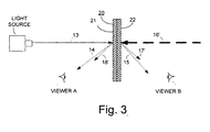
- the inventive screen 20 shown in FIG. 3 has a light-diffusive film 21 applied to a light-absorption film 22.
- a preferred embodiment of the present invention is shown having the light-diffusive film 21 facing the light source to receive the projected image thereon and the light-absorption film 22 facing sunlight in order to absorb the same.
- the projected image light from a light source is incident on the light-diffusive film 21 and observer A views the reflected image designated by dotted-line arrows 14.
- observer B views the transmitted image designated by dotted-line arrows 15 as it passes through the screen.
- Sunlight is shown by the weighted dashed-line arrow 16', with the arrow indicating the direction of the incident light.
- the manner in which such sunlight can be reflected from the light-absorption film 22 before it enters screen 20 is designated schematically by the shortened dotted-line arrow 17'.
- a large portion of sunlight is absorbed which results in a relatively small amount of sunlight being both reflected as designated schematically by the shortened dotted-line arrow 17' and transmitted through screen 20.
- FIG. 4a shows an enlarged schematic cross-section of one embodiment of the inventive rear-projection screen 30.
- Screen 30 includes a light-diffusive film 31 and a light-absorption film 33.
- Film 31 has a first surface 31a and an opposing second surface 31b and includes a plurality of light-diffusing particles 32 embedded and dispersed therein.
- Film 33 has a first surface 33a and an opposing second surface 33b and includes a plurality of light-absorbing particles 34 embedded and dispersed therein. As illustrated, the second surface 31b of film 31 is affixed to first surface 33a of film 33 which can be accomplished by fusing these surfaces together under heat and pressure.
- FIG. 4b shows an enlarged schematic cross-section of another embodiment of the inventive rear-projection screen 40.
- Screen 40 includes a light-diffusive film 31, a light-absorption film 43 and an adhesive 45.
- Adhesive 45 may comprise any transparent pressure sensitive adhesive and may include a repositionable transparent pressure sensitive adhesive.
- adhesive 45 comprises an acrylic-based transparent pressure sensitive adhesive.
- Film 41 has a first surface 41a and an opposing second surface 41b and includes a plurality of light-diffusing particles 32 embedded and dispersed therein.
- Film 43 has a first surface 43a and an opposing second surface 43b and includes a plurality of light-absorbing particles 34 embedded and dispersed therein.
- adhesive layer 45 joins second surface 41b of film 41 to first surface 33a of film 33.
- FIGS. 5a and 5b show enlarged schematic cross-sections of embodiments of the inventive rear-projection screen capable of being mounted to the surface of a planar transparent rigid substrate or between two planar transparent rigid substrates.
- a rear-projection screen 50 may be adapted to be temporarily or permanently mounted to a planar transparent rigid substrate 51 such as, for example, a pane glass.
- Screen 50 is substantially identical to screen 30 as depicted in FIG. 4a and further includes a transparent pressure sensitive adhesive 45 positioned between the second surface 33b of light-absorption film 33 and rigid substrate 51.
- FIG. 5b illustrates screen 60 adapted to be permanently mounted between two planar transparent rigid substrates 51 and 52.
- Screen 60 is substantially identical to screen 50 and further includes a second transparent pressure sensitive adhesive 46 positioned between the first surface 31b of light-diffusive film 31 and rigid substrate 52. It is contemplated that adhesive 46 may be the same or different transparent pressure sensitive adhesive as adhesive 45.
- FIGS. 6a and 6b show enlarged schematic cross-sections of alternative embodiments of the inventive rear-projection screen capable of being mounted to the surface of a planar transparent rigid substrate or between two planar transparent rigid substrates.
- screen 70 includes a light-diffusive film 31 affixed to a first side of rigid substrate 51 via a transparent pressure sensitive adhesive 45 and a light-absorption layer 33 affixed to the opposite second side of rigid substrate 51 via a second transparent pressure sensitive adhesive 46.
- screen 80 is adapted to be mounted between two planar transparent rigid substrates 52 and 53.
- screen 80 is substantially identical to screen 70 and further comprises a third transparent pressure sensitive adhesive 47 disposed between the second surface 33b of light-absorption film 33 and rigid substrate 53, and a fourth transparent pressure sensitive adhesive 48 disposed between rigid substrate 52 and the first surface 31a of light-diffusive film 31.
- transparent pressure sensitive adhesives 45, 46, 47 and 48 may be the same or different transparent pressure sensitive adhesives.
- transparent pressure sensitive adhesives 45, 46, 47 and 48 may be applied as a coating over an entire surface of a film or substrate or portions thereof, or as individual spots on a surface of the film or substrate.
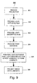
- FIG. 7 a flowchart 100 depicts one technique for creating a rear-projection screen in accordance with embodiments depicted in FIGS. 5a and 5b .
- the following steps are contemplated in this order:
- this method for creating a rear-projection screen may further include the following optional steps as indicated by the dashed-line arrows:
- this method for creating a rear-projection screen may further include the following optional steps of:
- FIG. 8 a flowchart 200 depicts one technique for creating a rear-projection screen in accordance with the embodiment depicted in FIG. 6a .
- the following steps are contemplated in this order:
- a flowchart 300 depicts one method for displaying a projected image onto a window with the use of a rear-projection screen in accordance with the present invention.
- the following steps are contemplated in this order:
- said first film may exhibit a visible light transmittance of between 60 to 80%.
- said first film may exhibit a visible light absorbance of between 0 to 15%.
- said second film may exhibit a visible light transmittance of between 35 to 60%.
- said second film may exhibit a visible light absorbance of between 40 to 60%.
- Said first surface of said second film may be in direct contact with said second surface of said first film.
- Said projection screen may further comprise a transparent pressure sensitive first adhesive.
- said first adhesive is in direct contact with said second surface of said second film.
- Said screen may be affixed to a planar transparent rigid substrate such that said first adhesive is positioned between said first film and said substrate, and said first film may be in direct contact with said second film.
- Said projection screen may further comprise a transparent pressure sensitive second adhesive in direct contact with said first surface of said first film.
- Said screen may be positioned between said first substrate and a planar transparent rigid second substrate, and said first film may be in direct contact with said second film.
- Said first adhesive may be in direct contact with said second surface of said first film and positioned between said first film and said second film.
- Said projection screen may further comprise a transparent pressure sensitive second adhesive in direct contact with said first surface of said second film.
- Said screen may be affixed to a planar transparent rigid substrate such that substrate is positioned between and in direct contact with said first and second adhesives.
- Said first adhesive may be e.g. an acrylic-based pressure sensitive adhesive.
- Said second adhesive may be e.g. an acrylic-based pressure sensitive adhesive.
- Said projection screen may further comprise a release liner in direct contact with said pressure sensitive adhesive.
- thermoplastic matrix of the inventive projection screen may comprises a polymer selected from the group consisting of polyvinyl chloride, polyester and polyolefin.
- Said polymer may be e.g. polyvinyl chloride.
- Said light-diffusing particles may comprise organic, inorganic, metallic light-diffusing particles or combinations thereof.
- Said light-diffusing particles may be inorganic light-diffusing particles.
- Said inorganic light-diffusing particles may comprise barium sulfate.
- Said barium sulfate may be present in an amount of between 15 to 20% by weight relative to the entire weight of said first film.
- Said light-diffusing particles may also comprise both inorganic and metallic light-diffusing particles.
- Said metallic light-diffusing particles may comprise aluminum.
- Said aluminum may be present in an amount of between 0 to 1.0% by weight relative to the entire weight of said first film. Especially, said aluminum may be present in an amount of between 0.4 to 0.8% by weight relative to the entire weight of said first film.
- Said light-absorbing particles may comprise a colorant.
- Said colorant may e.g. comprise carbon black.
- Said carbon black may be present in an amount of between 0.05 to 0.5% by weight relative to the entire weight of said second film. Especially, said carbon black may be present in an amount of between 0.05 to 0.3% by weight relative to the entire weight of said second film.
- Said screen may exhibit a visible light reflectance of between 0 to 25%.
- Said screen may exhibit a total solar energy transmittance of between 25 to 45%.
- Said screen may particularly be flexible.
- a rear-projection screen comprising:
- thermoplastic matrix may be polyvinyl chloride.
- Said metallic light-diffusing particles may be present in an amount of between 0.4 to 0.8% by weight relative to the entire weight of said first film.
- Said inorganic light-diffusing particles may barium sulfate.
- Said metallic light-diffusing particles may aluminum.
- Said light-absorbing colorant particles may be carbon black.
- Said carbon black may be present in an amount of between 0.05 to 0.3% by weight relative to the entire weight of said second film.
- Said first film may exhibit a visible light transmittance of between 60 to 80%.
- Said first film may exhibit a visible light absorbance of between 0 to 15%.
- Said second film may exhibit a visible light transmittance of between 35 to 60%.
- Said second film may exhibit a visible light absorbance of between 40 to 60%.
- Said screen may exhibit a visible light reflectance of between 10 to 25%.
- Said screen may exhibit a total solar energy transmittance of between 25 to 45%.
- Said screen may especially be flexible.
- said screen may be affixed to a planar transparent rigid substrate such that said adhesive is position between said second film and said substrate.
- Said projection screen may further comprise a transparent pressure sensitive second adhesive in direct contact with said first surface of said first film.
- Said screen may be positioned between a planar transparent rigid first substrate and a planar transparent rigid second substrate, and said first film may be in direct contact with said second film.
- a rear-projection screen comprising:
- thermoplastic matrix may be polyvinyl chloride.
- Said metallic light-diffusing particles may be present in an amount of between 0.4 to 0.8% by weight relative to the entire weight of said first film.
- Said inorganic light-diffusing particles may be barium sulfate.
- Said metallic light-diffusing particles may be aluminum.
- Said light-absorbing colorant particles may be carbon black.
- Said carbon black may be present in an amount of between 0.05 to 0.3% by weight relative to the entire weight of said second film.
- Said first film may exhibit a visible light transmittance of between 60 to 80%.
- Said first film may exhibit a visible light absorbance of between 0 to 15%.
- Said second film may exhibit a visible light transmittance of between 35 to 60%.
- Said second film may exhibit a visible light absorbance of between 40 to 60%.
- Said screen may exhibit a visible light reflectance of between 0 to 25%.
- Said screen may exhibit a total solar energy transmittance of between 25 to 45%.
- Said screen may especially be flexible.
- Said screen may be affixed to a planar transparent rigid substrate such that substrate is positioned between said first adhesive and said second adhesive.
- a method for forming a rear-projection screen comprising:
- Said method may further comprise applying a transparent pressure sensitive adhesive to said second surface of said second film.
- Said method may further comprise affixing said laminate to a planar transparent rigid substrate such that said adhesive is positioned between said laminate and said substrate, and said first film is in direct contact with said second film.
- Said method may further comprise applying a transparent pressure sensitive adhesive to said first surface of said first film.
- Said method may further comprise affixing said laminate to and between a planar transparent rigid first substrate and to a planar transparent rigid second substrate, such that said first film is in direct contact with said second film.
- said first film may comprise an amorphous thermoplastic matrix selected from the group consisting of polyvinyl chloride, polyester and polyolefin, a plurality of inorganic light-diffusing particles dispersed therein in an amount of between 15 to 20% by weight relative to the entire weight of said first film and a plurality of light diffusing metallic particles dispersed therein in an amount of between 0 to 1.0% by weight relative to the entire weight of said first film.
- said second film may comprise a thermoplastic matrix selected from the group consisting of polyvinyl chloride, polyester and polyolefin; and a plurality of light-absorbing colorant particles dispersed therein in an amount of between 0.05 to 0.5% by weight relative to the entire weight of said second film.
- said inorganic light-diffusing particles may be barium sulfate.
- said metallic light-diffusing particles may be aluminum.
- said light-absorbing colorant particles may be carbon black.
- thermoplastic matrix may especially be polyvinyl chloride.
- Said adhesive may particularly be an acrylic-based pressure sensitive adhesive.
- a method for forming a rear-projection screen comprising:
- said first film may comprise an amorphous thermoplastic matrix selected from the group consisting of polyvinyl chloride, polyester and polyolefin, a plurality of inorganic light-diffusing particles dispersed therein in an amount of between 15 to 20% by weight relative to the entire weight of said first film and a plurality of metallic light-diffusing particles dispersed therein in an amount of between 0 to 1.0% by weight relative to the entire weight of said first film.
- said second film may comprise a thermoplastic matrix selected from the group consisting of polyvinyl chloride, polyester and polyolefin; and a plurality of light-absorbing colorant particles dispersed therein in an amount of between 0.05 to 0.5% by weight relative to the entire weight of said second film; wherein said first surface of said second film may be in direct contact with said second surface of said first film.
- said inorganic light-diffusing particles may be barium sulfate.
- said metallic light-diffusing particles may be aluminum.
- said light-absorbing colorant particles may be carbon black.
- thermoplastic matrix may be e.g. polyvinyl chloride.
- Said first and second adhesives may each comprise an acrylic-based pressure sensitive adhesive.
- a method for displaying a projected image onto a window comprising:
- said thermoplastic matrix may be polyvinyl chloride.
- Said metallic light-diffusing particles may be present in an amount of between 0.4 to 0.8% by weight relative to the entire weight of said first film.
- Said inorganic light-diffusing particles may be barium sulfate.
- Said metallic light-diffusing particles may be aluminum.
- Said light-absorbing colorant particles may be carbon black.
- Said carbon black may be present in an amount of between 0.05 to 0.3% by weight relative to the entire weight of said second film.
- said first film may exhibit a visible light transmittance of between 60 to 80% and a visible light absorbance of between 0 to 15%.
- Said second film may exhibit a visible light transmittance of between 35 to 60% and a visible light absorbance of between 40 to 60%.
- Said laminate may exhibit a visible light transmittance of between 25 to 50% and a visible light absorbance of between 35 to 60%.
- Said laminate may exhibit a visible light reflectance of between 0 to 25%.
- Said laminate may exhibit a total solar energy transmittance of between 25 to 45%.
- Comparative example 1 was a light-diffusive film similar to the one described in FIG. 1 .
- the light-diffusive film was a MACal® Glass Décor 700 film obtained from MACtac Europe SA which included a translucent monolayer film having amorphous polyvinyl chloride matrix with between 15 to 20% by weight relative to the entire weight the film of barium sulfate particles and between 0.4 to 0.8% by weight relative to the entire weight the film of aluminum particles each incorporated and dispersed therein.
- the film had an approximate overall thickness of about 75 to 80 microns.
- Comparative example 2 was a monolayer light-diffusive film identical to that described for Comparative Example 1, except that about 0.2% by weight relative to the entire weight the film of carbon black was incorporated into the polyvinyl chloride matrix.
- Comparative example 3 was a monolayer light-absorptive film similar to the one described in FIG. 2 .
- the light-absorptive film consisted of a polyethylene terephthalate matrix having 0.2% by weight relative to the entire weight the film of carbon black incorporated therein.
- Comparative example 4 was similar to Comparative Example 3, except for an extra light-absorptive film having a identical composition was added. The two light-absorptive films were fused together by heat and pressure to form a two-ply laminate.
- Comparative example 5 was a monolayer light-absorptive film similar to the one described in FIG. 2 .
- the light-absorptive film consisted of a polyvinyl chloride matrix with about 0.2% by weight relative to the entire weight the film of carbon black incorporated therein.
- Example 1 included a light-diffusive film and a light-absorptive film similar to the laminate described in FIG. 3 .
- the light-diffusive film was identical to that described for Comparative Example 1.
- the light-absorptive film was a transparent monolayer film having a matrix of amorphous polyethylene terephthalate and about 0.2% by weight relative to the entire weight of the film of carbon black incorporated therein.
- the light-diffusive and light-absorptive films were adhesively laminated together by use of a transparent acrylic pressure sensitive adhesive to form a two-ply laminate.
- Example 2 was similar to Example 1, except that an extra light-absorptive film having an identical composition as that described in Example 1 was added.
- the light-diffusive and light-absorptive films were fused together by heat and pressure form a three-ply laminate.
- Example 3 was similar to Example 2, except that an extra light-absorptive film having an identical composition as that described in Example 1 was added.
- the light-diffusive film and light-absorptive films were fused together by heat and pressure form a four-ply laminate.
- Example 4 was similar to Example 1, except for the light-absorptive film was a transparent monolayer film having a matrix of amorphous polyvinyl chloride with between 0.05 to 0.3% by weight relative to the entire weight of film of carbon black incorporated therein.
- the light-diffusive and light-absorptive films were fused together by heat and pressure to form a two-ply laminate.
- Example 5 was identical to Example 4, except that the laminate was mounted onto a 4 mm pane of glass similar to that described in FIG. 5a .
- Table 1 illustrates the various spectral properties of the rear-projection screens described above for Comparative Examples 1, 2, 3, 4 and 5, and Examples 1, 2, 3, 4, and 5. Prior to measuring the spectral properties, a layer of pressure sensitive adhesive applied to the surface of each screen. It will be understood that the spectral properties were measured in accordance with European Norm EN 410.
Landscapes
- Physics & Mathematics (AREA)
- General Physics & Mathematics (AREA)
- Overhead Projectors And Projection Screens (AREA)
- Optical Elements Other Than Lenses (AREA)
Priority Applications (1)
| Application Number | Priority Date | Filing Date | Title |
|---|---|---|---|
| PL10006870T PL2302450T3 (pl) | 2009-07-02 | 2010-07-02 | Ekran z tylną projekcją |
Applications Claiming Priority (1)
| Application Number | Priority Date | Filing Date | Title |
|---|---|---|---|
| US12/496,793 US8000006B2 (en) | 2009-07-02 | 2009-07-02 | Rear-projection screen |
Publications (3)
| Publication Number | Publication Date |
|---|---|
| EP2302450A2 true EP2302450A2 (de) | 2011-03-30 |
| EP2302450A3 EP2302450A3 (de) | 2011-12-14 |
| EP2302450B1 EP2302450B1 (de) | 2017-05-24 |
Family
ID=42941950
Family Applications (1)
| Application Number | Title | Priority Date | Filing Date |
|---|---|---|---|
| EP10006870.9A Active EP2302450B1 (de) | 2009-07-02 | 2010-07-02 | Rückprojektionsbildschirm |
Country Status (4)
| Country | Link |
|---|---|
| US (1) | US8000006B2 (de) |
| EP (1) | EP2302450B1 (de) |
| ES (1) | ES2629447T3 (de) |
| PL (1) | PL2302450T3 (de) |
Families Citing this family (16)
| Publication number | Priority date | Publication date | Assignee | Title |
|---|---|---|---|---|
| DE102005010523A1 (de) * | 2005-03-04 | 2006-09-07 | Fraunhofer-Gesellschaft zur Förderung der angewandten Forschung e.V. | Kontrasterhöhender Rückprojektionsschirm |
| BE1018074A3 (fr) * | 2008-03-31 | 2010-04-06 | Mactac Europ Sa | Structure adhesive a cristaux liquides. |
| JP6452620B2 (ja) * | 2013-01-08 | 2019-01-16 | コベストロ、ドイチュラント、アクチエンゲゼルシャフトCovestro Deutschland Ag | 「昼/夜」効果を有するリアプロジェクションフィルム |
| CN104749870B (zh) * | 2013-12-25 | 2017-07-25 | 常州亚玛顿股份有限公司 | 双面投影幕及包含彼的双面投影显示系统 |
| JP6563383B2 (ja) * | 2014-04-14 | 2019-08-21 | 国立大学法人東京工業大学 | 透明スクリーン用フィルムおよびその製造方法ならびにそれを備えた透明スクリーン |
| US9848169B2 (en) * | 2014-09-25 | 2017-12-19 | Steve H. McNelley | Transparent projection communication terminals |
| US11750772B2 (en) | 2014-09-25 | 2023-09-05 | Steve H. McNelley | Rear illuminated transparent communication terminals |
| US10129506B2 (en) | 2014-09-25 | 2018-11-13 | Steve H. McNelley | Advanced transparent projection communication terminals |
| US10841535B2 (en) | 2014-09-25 | 2020-11-17 | Steve H. McNelley | Configured transparent communication terminals |
| US10298877B2 (en) | 2014-09-25 | 2019-05-21 | Steve H. McNelley | Communication stage and display systems |
| US11258983B2 (en) | 2014-09-25 | 2022-02-22 | Steve H. McNelley | Immersive communication terminals |
| US11099465B2 (en) | 2014-09-25 | 2021-08-24 | Steve H. McNelley | Communication stage and display systems |
| CN104977791B (zh) * | 2015-05-22 | 2017-01-18 | 上海理鑫光学科技有限公司 | 一种低成本投影显示系统 |
| CN110007552B (zh) * | 2018-12-14 | 2021-07-20 | 北京宝江科技有限公司 | 用于投影的透明薄膜和投影系统 |
| JP7259482B2 (ja) * | 2019-03-28 | 2023-04-18 | 大日本印刷株式会社 | 反射スクリーン及びそれを用いた投射システム |
| CN115917427A (zh) * | 2020-06-08 | 2023-04-04 | 富士胶片株式会社 | 水箱用透明屏幕、水箱及透明图像显示系统 |
Citations (6)
| Publication number | Priority date | Publication date | Assignee | Title |
|---|---|---|---|---|
| US3832032A (en) | 1972-04-25 | 1974-08-27 | Sony Corp | Lenticular rear projection screen |
| US4003080A (en) | 1975-06-02 | 1977-01-11 | Laser Video, Inc. | Large screen video display systems and methods therefor |
| US4573764A (en) | 1983-12-30 | 1986-03-04 | North American Philips Consumer Electronics Corp. | Rear projection screen |
| US4666248A (en) | 1985-12-20 | 1987-05-19 | U. S. Philips Corporation | Rear-projection screen |
| US6204971B1 (en) | 1999-05-14 | 2001-03-20 | 3M Innovative Properties Company | Glass microspheres for use in films and projection screen displays and methods |
| US7142361B2 (en) | 2003-12-11 | 2006-11-28 | 3M Innovative Properties Company | Optical material adhesive, film including optical material and projection screen including film |
Family Cites Families (34)
| Publication number | Priority date | Publication date | Assignee | Title |
|---|---|---|---|---|
| US3552822A (en) * | 1968-06-07 | 1971-01-05 | Gerald Altman | Rear projection screen |
| USRE28516E (en) * | 1969-07-01 | 1975-08-12 | Polymeric rear projection screens | |
| US3655262A (en) * | 1970-09-04 | 1972-04-11 | Eastman Kodak Co | Rear projection screen |
| US3682530A (en) * | 1970-09-24 | 1972-08-08 | Eastman Kodak Co | Polymeric rear projection screens |
| JPS5189419A (de) * | 1975-02-03 | 1976-08-05 | ||
| US4083626A (en) * | 1975-04-04 | 1978-04-11 | Fuji Photo Film Co., Ltd. | Rear projection screens |
| GB2022861A (en) | 1978-04-05 | 1979-12-19 | Freen Ltd | Rear Projection Screen |
| CA1245890A (en) | 1982-12-27 | 1988-12-06 | G.B. Kirby Meacham | System of projecting three-dimensional images |
| US5361164A (en) * | 1992-06-17 | 1994-11-01 | Walltalkers | Projection markerboard |
| JP2926454B2 (ja) * | 1992-10-02 | 1999-07-28 | 大日本印刷株式会社 | 反射型映写スクリーン |
| US5563738A (en) * | 1993-09-03 | 1996-10-08 | Jenmar Visual Systems | Light transmitting and dispersing filter having low reflectance |
| US5631163A (en) * | 1995-10-23 | 1997-05-20 | Bayer Corporation | Method for the determination of specific gravity of fluids |
| US5870224A (en) | 1995-10-25 | 1999-02-09 | Toppan Printing Company Limited | Lenticular sheet, rear-projection screen or TV using the same, and fabrication method for said lenticular sheet |
| WO2000038005A1 (en) * | 1998-12-18 | 2000-06-29 | Mitsubishi Rayon Co., Ltd. | Transmission screen |
| US6440551B1 (en) * | 1999-06-14 | 2002-08-27 | Cpfilms, Inc. | Light-stable colored transparent composite films |
| JP2001100318A (ja) * | 1999-07-27 | 2001-04-13 | Kikuchi Kagaku Kenkyusho:Kk | 透過型映写スクリーン |
| US6624933B2 (en) * | 2001-01-15 | 2003-09-23 | Kuraray Co., Ltd. | Front faceplate used in rear projection type screen, front-faceplate-equipped lenticular lens sheet, and rear projection type screen |
| US6727313B2 (en) * | 2001-01-17 | 2004-04-27 | 3M Innovative Properties Company | Polymeric compositions and articles with anisotropic light scattering and methods of making and using |
| US6819486B2 (en) * | 2001-01-17 | 2004-11-16 | 3M Innovative Properties Company | Projection screen having elongated structures |
| AT414051B (de) * | 2001-01-18 | 2006-08-15 | Eckelt Glas Gmbh | Projektionswand mit einem glasschirm |
| JP2002292775A (ja) | 2001-03-26 | 2002-10-09 | Three M Innovative Properties Co | グラフィックス形成用シート及びグラフィックス表示シート |
| US6870670B2 (en) * | 2001-04-06 | 2005-03-22 | 3M Innovative Properties Company | Screens and methods for displaying information |
| US7057805B2 (en) * | 2001-10-22 | 2006-06-06 | Commonwealth Laminating & Coating, Inc. | Solar control film containing carbon black and process for preparing the solar control film |
| CN1592857A (zh) * | 2001-11-09 | 2005-03-09 | 3M创新有限公司 | 高反差光学薄膜 |
| JP4190253B2 (ja) * | 2002-10-31 | 2008-12-03 | 大日本印刷株式会社 | コントラスト向上シートおよび背面投射型スクリーン |
| FR2849932B1 (fr) * | 2003-01-15 | 2005-02-18 | Saint Gobain | Ecran de retroprojection et/ou de projection |
| US7453635B2 (en) * | 2004-08-10 | 2008-11-18 | Fusion Optix Inc. | Imaging material with improved contrast |
| US20060061861A1 (en) * | 2004-09-23 | 2006-03-23 | Reflexite Corporation | High performance rear-projection screen |
| JP4676190B2 (ja) * | 2004-11-25 | 2011-04-27 | 大日本印刷株式会社 | 光拡散シート及び透過型スクリーン |
| DE202005013031U1 (de) * | 2005-08-16 | 2005-11-10 | Biggair Gmbh | Transportable Großbildleinwand |
| US7253953B2 (en) * | 2005-08-29 | 2007-08-07 | Stewart Filmscreen Corporation | Polymer sheet for projection screen |
| KR20080087238A (ko) * | 2007-03-26 | 2008-10-01 | 엘지전자 주식회사 | 플라즈마 디스플레이 패널의 콘트라스트 향상 광학 시트 및그 제작 방법 |
| US7923675B2 (en) * | 2007-06-06 | 2011-04-12 | 3M Innovative Properties Company | Projection system having avirtual mask |
| US20090004478A1 (en) * | 2007-06-29 | 2009-01-01 | 3M Innovative Properties Company | Flexible hardcoat compositions, articles, and methods |
-
2009
- 2009-07-02 US US12/496,793 patent/US8000006B2/en active Active
-
2010
- 2010-07-02 ES ES10006870.9T patent/ES2629447T3/es active Active
- 2010-07-02 EP EP10006870.9A patent/EP2302450B1/de active Active
- 2010-07-02 PL PL10006870T patent/PL2302450T3/pl unknown
Patent Citations (8)
| Publication number | Priority date | Publication date | Assignee | Title |
|---|---|---|---|---|
| US3832032A (en) | 1972-04-25 | 1974-08-27 | Sony Corp | Lenticular rear projection screen |
| US4003080A (en) | 1975-06-02 | 1977-01-11 | Laser Video, Inc. | Large screen video display systems and methods therefor |
| US4573764A (en) | 1983-12-30 | 1986-03-04 | North American Philips Consumer Electronics Corp. | Rear projection screen |
| US4666248A (en) | 1985-12-20 | 1987-05-19 | U. S. Philips Corporation | Rear-projection screen |
| US6204971B1 (en) | 1999-05-14 | 2001-03-20 | 3M Innovative Properties Company | Glass microspheres for use in films and projection screen displays and methods |
| USRE38245E1 (en) | 1999-05-14 | 2003-09-09 | 3M Innovative Properties Company | Glass microspheres for use in films and projection screen displays and methods |
| US6765720B2 (en) | 1999-05-14 | 2004-07-20 | 3M Innovative Properties Company | Glass microspheres for use in films and projection screen displays |
| US7142361B2 (en) | 2003-12-11 | 2006-11-28 | 3M Innovative Properties Company | Optical material adhesive, film including optical material and projection screen including film |
Also Published As
| Publication number | Publication date |
|---|---|
| US8000006B2 (en) | 2011-08-16 |
| EP2302450A3 (de) | 2011-12-14 |
| US20110002036A1 (en) | 2011-01-06 |
| PL2302450T3 (pl) | 2017-10-31 |
| EP2302450B1 (de) | 2017-05-24 |
| ES2629447T3 (es) | 2017-08-09 |
Similar Documents
| Publication | Publication Date | Title |
|---|---|---|
| EP2302450B1 (de) | Rückprojektionsbildschirm | |
| US9946147B2 (en) | Transmission-type transparent screen, image display system and image display method | |
| CN105408777B (zh) | 反射屏、反射屏的制造方法、屏幕框体和影像显示系统 | |
| US9977322B2 (en) | Film or sheet, and screen | |
| US20070019290A1 (en) | Projection screen and projection system containing same | |
| MXPA04009570A (es) | Articulos fluorescentes que tienen multiples capas de pelicula. | |
| JP2005107011A (ja) | 反射スクリーン、それを用いた表示方法および表示装置 | |
| CN101646557A (zh) | 多层屏幕复合材料 | |
| JP2017198807A (ja) | 透過型透明スクリーン、映像表示システムおよび映像表示方法 | |
| JP6142251B2 (ja) | 投映スクリーン | |
| JP2012514771A (ja) | 高コントラストのフロント投射スクリーン | |
| US20060134434A1 (en) | Plastic sheet | |
| JP2016009149A (ja) | 透過投映スクリーン | |
| US6312132B1 (en) | Fluorescent red article and retroreflective article made therefrom | |
| CN100542802C (zh) | 有多个薄膜层的荧光制品 | |
| JP2016109778A (ja) | 透過型透明スクリーン、映像表示システムおよび映像表示方法 | |
| WO2006004798A2 (en) | Multilayer optical display device | |
| JP6368911B2 (ja) | 透過投映スクリーン | |
| JP6507563B2 (ja) | 反射スクリーン、映像表示システム | |
| JPH10104747A (ja) | 反射型映写スクリーン | |
| JPH09211729A (ja) | 反射型スクリーン | |
| JP6318448B2 (ja) | 透過投映スクリーン | |
| JP3113504U (ja) | 透過型スクリーン | |
| KR20070110173A (ko) | 투사 스크린 | |
| CN115390351B (zh) | 长焦投影幕布 |
Legal Events
| Date | Code | Title | Description |
|---|---|---|---|
| PUAI | Public reference made under article 153(3) epc to a published international application that has entered the european phase |
Free format text: ORIGINAL CODE: 0009012 |
|
| AK | Designated contracting states |
Kind code of ref document: A2 Designated state(s): AL AT BE BG CH CY CZ DE DK EE ES FI FR GB GR HR HU IE IS IT LI LT LU LV MC MK MT NL NO PL PT RO SE SI SK SM TR |
|
| AX | Request for extension of the european patent |
Extension state: BA ME RS |
|
| PUAL | Search report despatched |
Free format text: ORIGINAL CODE: 0009013 |
|
| AK | Designated contracting states |
Kind code of ref document: A3 Designated state(s): AL AT BE BG CH CY CZ DE DK EE ES FI FR GB GR HR HU IE IS IT LI LT LU LV MC MK MT NL NO PL PT RO SE SI SK SM TR |
|
| AX | Request for extension of the european patent |
Extension state: BA ME RS |
|
| RIC1 | Information provided on ipc code assigned before grant |
Ipc: G03B 21/60 20060101AFI20111109BHEP |
|
| 17P | Request for examination filed |
Effective date: 20120609 |
|
| 17Q | First examination report despatched |
Effective date: 20120709 |
|
| RAP1 | Party data changed (applicant data changed or rights of an application transferred) |
Owner name: MORGAN ADHESIVES COMPANY LLC |
|
| RAP1 | Party data changed (applicant data changed or rights of an application transferred) |
Owner name: EVERGREEN HOLDING S.A.R.L. |
|
| RAP1 | Party data changed (applicant data changed or rights of an application transferred) |
Owner name: EVERGREEN HOLDING S.A.R.L. |
|
| GRAP | Despatch of communication of intention to grant a patent |
Free format text: ORIGINAL CODE: EPIDOSNIGR1 |
|
| STAA | Information on the status of an ep patent application or granted ep patent |
Free format text: STATUS: GRANT OF PATENT IS INTENDED |
|
| INTG | Intention to grant announced |
Effective date: 20161215 |
|
| RIN1 | Information on inventor provided before grant (corrected) |
Inventor name: SIRAUX, GUY Inventor name: PEROTTI, DANIEL |
|
| GRAS | Grant fee paid |
Free format text: ORIGINAL CODE: EPIDOSNIGR3 |
|
| GRAA | (expected) grant |
Free format text: ORIGINAL CODE: 0009210 |
|
| STAA | Information on the status of an ep patent application or granted ep patent |
Free format text: STATUS: THE PATENT HAS BEEN GRANTED |
|
| RAP1 | Party data changed (applicant data changed or rights of an application transferred) |
Owner name: AVERY DENNISON CORPORATION |
|
| AK | Designated contracting states |
Kind code of ref document: B1 Designated state(s): AL AT BE BG CH CY CZ DE DK EE ES FI FR GB GR HR HU IE IS IT LI LT LU LV MC MK MT NL NO PL PT RO SE SI SK SM TR |
|
| REG | Reference to a national code |
Ref country code: GB Ref legal event code: FG4D |
|
| REG | Reference to a national code |
Ref country code: CH Ref legal event code: EP |
|
| REG | Reference to a national code |
Ref country code: IE Ref legal event code: FG4D |
|
| REG | Reference to a national code |
Ref country code: AT Ref legal event code: REF Ref document number: 896302 Country of ref document: AT Kind code of ref document: T Effective date: 20170615 |
|
| REG | Reference to a national code |
Ref country code: FR Ref legal event code: PLFP Year of fee payment: 8 |
|
| REG | Reference to a national code |
Ref country code: DE Ref legal event code: R096 Ref document number: 602010042514 Country of ref document: DE |
|
| REG | Reference to a national code |
Ref country code: ES Ref legal event code: FG2A Ref document number: 2629447 Country of ref document: ES Kind code of ref document: T3 Effective date: 20170809 |
|
| REG | Reference to a national code |
Ref country code: NL Ref legal event code: FP |
|
| REG | Reference to a national code |
Ref country code: LT Ref legal event code: MG4D |
|
| REG | Reference to a national code |
Ref country code: AT Ref legal event code: MK05 Ref document number: 896302 Country of ref document: AT Kind code of ref document: T Effective date: 20170524 |
|
| PG25 | Lapsed in a contracting state [announced via postgrant information from national office to epo] |
Ref country code: FI Free format text: LAPSE BECAUSE OF FAILURE TO SUBMIT A TRANSLATION OF THE DESCRIPTION OR TO PAY THE FEE WITHIN THE PRESCRIBED TIME-LIMIT Effective date: 20170524 Ref country code: AT Free format text: LAPSE BECAUSE OF FAILURE TO SUBMIT A TRANSLATION OF THE DESCRIPTION OR TO PAY THE FEE WITHIN THE PRESCRIBED TIME-LIMIT Effective date: 20170524 Ref country code: GR Free format text: LAPSE BECAUSE OF FAILURE TO SUBMIT A TRANSLATION OF THE DESCRIPTION OR TO PAY THE FEE WITHIN THE PRESCRIBED TIME-LIMIT Effective date: 20170825 Ref country code: HR Free format text: LAPSE BECAUSE OF FAILURE TO SUBMIT A TRANSLATION OF THE DESCRIPTION OR TO PAY THE FEE WITHIN THE PRESCRIBED TIME-LIMIT Effective date: 20170524 Ref country code: NO Free format text: LAPSE BECAUSE OF FAILURE TO SUBMIT A TRANSLATION OF THE DESCRIPTION OR TO PAY THE FEE WITHIN THE PRESCRIBED TIME-LIMIT Effective date: 20170824 Ref country code: LT Free format text: LAPSE BECAUSE OF FAILURE TO SUBMIT A TRANSLATION OF THE DESCRIPTION OR TO PAY THE FEE WITHIN THE PRESCRIBED TIME-LIMIT Effective date: 20170524 |
|
| PG25 | Lapsed in a contracting state [announced via postgrant information from national office to epo] |
Ref country code: IS Free format text: LAPSE BECAUSE OF FAILURE TO SUBMIT A TRANSLATION OF THE DESCRIPTION OR TO PAY THE FEE WITHIN THE PRESCRIBED TIME-LIMIT Effective date: 20170924 Ref country code: LV Free format text: LAPSE BECAUSE OF FAILURE TO SUBMIT A TRANSLATION OF THE DESCRIPTION OR TO PAY THE FEE WITHIN THE PRESCRIBED TIME-LIMIT Effective date: 20170524 Ref country code: BG Free format text: LAPSE BECAUSE OF FAILURE TO SUBMIT A TRANSLATION OF THE DESCRIPTION OR TO PAY THE FEE WITHIN THE PRESCRIBED TIME-LIMIT Effective date: 20170824 Ref country code: SE Free format text: LAPSE BECAUSE OF FAILURE TO SUBMIT A TRANSLATION OF THE DESCRIPTION OR TO PAY THE FEE WITHIN THE PRESCRIBED TIME-LIMIT Effective date: 20170524 |
|
| PG25 | Lapsed in a contracting state [announced via postgrant information from national office to epo] |
Ref country code: DK Free format text: LAPSE BECAUSE OF FAILURE TO SUBMIT A TRANSLATION OF THE DESCRIPTION OR TO PAY THE FEE WITHIN THE PRESCRIBED TIME-LIMIT Effective date: 20170524 Ref country code: RO Free format text: LAPSE BECAUSE OF FAILURE TO SUBMIT A TRANSLATION OF THE DESCRIPTION OR TO PAY THE FEE WITHIN THE PRESCRIBED TIME-LIMIT Effective date: 20170524 Ref country code: SK Free format text: LAPSE BECAUSE OF FAILURE TO SUBMIT A TRANSLATION OF THE DESCRIPTION OR TO PAY THE FEE WITHIN THE PRESCRIBED TIME-LIMIT Effective date: 20170524 Ref country code: EE Free format text: LAPSE BECAUSE OF FAILURE TO SUBMIT A TRANSLATION OF THE DESCRIPTION OR TO PAY THE FEE WITHIN THE PRESCRIBED TIME-LIMIT Effective date: 20170524 Ref country code: CZ Free format text: LAPSE BECAUSE OF FAILURE TO SUBMIT A TRANSLATION OF THE DESCRIPTION OR TO PAY THE FEE WITHIN THE PRESCRIBED TIME-LIMIT Effective date: 20170524 |
|
| REG | Reference to a national code |
Ref country code: DE Ref legal event code: R097 Ref document number: 602010042514 Country of ref document: DE |
|
| PG25 | Lapsed in a contracting state [announced via postgrant information from national office to epo] |
Ref country code: SM Free format text: LAPSE BECAUSE OF FAILURE TO SUBMIT A TRANSLATION OF THE DESCRIPTION OR TO PAY THE FEE WITHIN THE PRESCRIBED TIME-LIMIT Effective date: 20170524 |
|
| REG | Reference to a national code |
Ref country code: CH Ref legal event code: PL |
|
| PLBE | No opposition filed within time limit |
Free format text: ORIGINAL CODE: 0009261 |
|
| STAA | Information on the status of an ep patent application or granted ep patent |
Free format text: STATUS: NO OPPOSITION FILED WITHIN TIME LIMIT |
|
| REG | Reference to a national code |
Ref country code: IE Ref legal event code: MM4A |
|
| PG25 | Lapsed in a contracting state [announced via postgrant information from national office to epo] |
Ref country code: LI Free format text: LAPSE BECAUSE OF NON-PAYMENT OF DUE FEES Effective date: 20170731 Ref country code: IE Free format text: LAPSE BECAUSE OF NON-PAYMENT OF DUE FEES Effective date: 20170702 Ref country code: CH Free format text: LAPSE BECAUSE OF NON-PAYMENT OF DUE FEES Effective date: 20170731 |
|
| 26N | No opposition filed |
Effective date: 20180227 |
|
| PG25 | Lapsed in a contracting state [announced via postgrant information from national office to epo] |
Ref country code: SI Free format text: LAPSE BECAUSE OF FAILURE TO SUBMIT A TRANSLATION OF THE DESCRIPTION OR TO PAY THE FEE WITHIN THE PRESCRIBED TIME-LIMIT Effective date: 20170524 |
|
| REG | Reference to a national code |
Ref country code: FR Ref legal event code: PLFP Year of fee payment: 9 |
|
| PG25 | Lapsed in a contracting state [announced via postgrant information from national office to epo] |
Ref country code: LU Free format text: LAPSE BECAUSE OF NON-PAYMENT OF DUE FEES Effective date: 20170702 |
|
| PGFP | Annual fee paid to national office [announced via postgrant information from national office to epo] |
Ref country code: PL Payment date: 20180619 Year of fee payment: 9 |
|
| PG25 | Lapsed in a contracting state [announced via postgrant information from national office to epo] |
Ref country code: MT Free format text: LAPSE BECAUSE OF NON-PAYMENT OF DUE FEES Effective date: 20170702 |
|
| PGFP | Annual fee paid to national office [announced via postgrant information from national office to epo] |
Ref country code: IT Payment date: 20180711 Year of fee payment: 9 |
|
| PG25 | Lapsed in a contracting state [announced via postgrant information from national office to epo] |
Ref country code: MC Free format text: LAPSE BECAUSE OF FAILURE TO SUBMIT A TRANSLATION OF THE DESCRIPTION OR TO PAY THE FEE WITHIN THE PRESCRIBED TIME-LIMIT Effective date: 20170524 Ref country code: HU Free format text: LAPSE BECAUSE OF FAILURE TO SUBMIT A TRANSLATION OF THE DESCRIPTION OR TO PAY THE FEE WITHIN THE PRESCRIBED TIME-LIMIT; INVALID AB INITIO Effective date: 20100702 |
|
| PGFP | Annual fee paid to national office [announced via postgrant information from national office to epo] |
Ref country code: NL Payment date: 20190627 Year of fee payment: 10 |
|
| PG25 | Lapsed in a contracting state [announced via postgrant information from national office to epo] |
Ref country code: CY Free format text: LAPSE BECAUSE OF NON-PAYMENT OF DUE FEES Effective date: 20170524 |
|
| PG25 | Lapsed in a contracting state [announced via postgrant information from national office to epo] |
Ref country code: MK Free format text: LAPSE BECAUSE OF FAILURE TO SUBMIT A TRANSLATION OF THE DESCRIPTION OR TO PAY THE FEE WITHIN THE PRESCRIBED TIME-LIMIT Effective date: 20170524 |
|
| PG25 | Lapsed in a contracting state [announced via postgrant information from national office to epo] |
Ref country code: TR Free format text: LAPSE BECAUSE OF FAILURE TO SUBMIT A TRANSLATION OF THE DESCRIPTION OR TO PAY THE FEE WITHIN THE PRESCRIBED TIME-LIMIT Effective date: 20170524 |
|
| PG25 | Lapsed in a contracting state [announced via postgrant information from national office to epo] |
Ref country code: PT Free format text: LAPSE BECAUSE OF FAILURE TO SUBMIT A TRANSLATION OF THE DESCRIPTION OR TO PAY THE FEE WITHIN THE PRESCRIBED TIME-LIMIT Effective date: 20170524 |
|
| PG25 | Lapsed in a contracting state [announced via postgrant information from national office to epo] |
Ref country code: AL Free format text: LAPSE BECAUSE OF FAILURE TO SUBMIT A TRANSLATION OF THE DESCRIPTION OR TO PAY THE FEE WITHIN THE PRESCRIBED TIME-LIMIT Effective date: 20170524 |
|
| REG | Reference to a national code |
Ref country code: ES Ref legal event code: FD2A Effective date: 20201126 |
|
| PG25 | Lapsed in a contracting state [announced via postgrant information from national office to epo] |
Ref country code: ES Free format text: LAPSE BECAUSE OF NON-PAYMENT OF DUE FEES Effective date: 20190703 |
|
| REG | Reference to a national code |
Ref country code: NL Ref legal event code: MM Effective date: 20200801 |
|
| REG | Reference to a national code |
Ref country code: BE Ref legal event code: MM Effective date: 20200731 |
|
| PG25 | Lapsed in a contracting state [announced via postgrant information from national office to epo] |
Ref country code: NL Free format text: LAPSE BECAUSE OF NON-PAYMENT OF DUE FEES Effective date: 20200801 |
|
| PG25 | Lapsed in a contracting state [announced via postgrant information from national office to epo] |
Ref country code: BE Free format text: LAPSE BECAUSE OF NON-PAYMENT OF DUE FEES Effective date: 20200731 |
|
| PG25 | Lapsed in a contracting state [announced via postgrant information from national office to epo] |
Ref country code: IT Free format text: LAPSE BECAUSE OF NON-PAYMENT OF DUE FEES Effective date: 20200702 |
|
| PG25 | Lapsed in a contracting state [announced via postgrant information from national office to epo] |
Ref country code: PL Free format text: LAPSE BECAUSE OF NON-PAYMENT OF DUE FEES Effective date: 20190702 |
|
| REG | Reference to a national code |
Ref country code: DE Ref legal event code: R081 Ref document number: 602010042514 Country of ref document: DE Owner name: AVERY DENNISON CORPORATION, MENTOR, US Free format text: FORMER OWNER: AVERY DENNISON CORPORATION, GLENDALE, CALIF., US |
|
| P01 | Opt-out of the competence of the unified patent court (upc) registered |
Effective date: 20230507 |
|
| PGFP | Annual fee paid to national office [announced via postgrant information from national office to epo] |
Ref country code: GB Payment date: 20250612 Year of fee payment: 16 |
|
| PGFP | Annual fee paid to national office [announced via postgrant information from national office to epo] |
Ref country code: FR Payment date: 20250612 Year of fee payment: 16 |
|
| PGFP | Annual fee paid to national office [announced via postgrant information from national office to epo] |
Ref country code: DE Payment date: 20250616 Year of fee payment: 16 |