EP2302761A1 - Système de commande de communications de réseau électrique - Google Patents
Système de commande de communications de réseau électrique Download PDFInfo
- Publication number
- EP2302761A1 EP2302761A1 EP10183876A EP10183876A EP2302761A1 EP 2302761 A1 EP2302761 A1 EP 2302761A1 EP 10183876 A EP10183876 A EP 10183876A EP 10183876 A EP10183876 A EP 10183876A EP 2302761 A1 EP2302761 A1 EP 2302761A1
- Authority
- EP
- European Patent Office
- Prior art keywords
- luminaire
- telegram
- information
- lights
- lamp
- Prior art date
- Legal status (The legal status is an assumption and is not a legal conclusion. Google has not performed a legal analysis and makes no representation as to the accuracy of the status listed.)
- Granted
Links
Images


Classifications
-
- H—ELECTRICITY
- H05—ELECTRIC TECHNIQUES NOT OTHERWISE PROVIDED FOR
- H05B—ELECTRIC HEATING; ELECTRIC LIGHT SOURCES NOT OTHERWISE PROVIDED FOR; CIRCUIT ARRANGEMENTS FOR ELECTRIC LIGHT SOURCES, IN GENERAL
- H05B47/00—Circuit arrangements for operating light sources in general, i.e. where the type of light source is not relevant
- H05B47/10—Controlling the light source
- H05B47/175—Controlling the light source by remote control
- H05B47/185—Controlling the light source by remote control via power line carrier transmission
-
- H—ELECTRICITY
- H04—ELECTRIC COMMUNICATION TECHNIQUE
- H04L—TRANSMISSION OF DIGITAL INFORMATION, e.g. TELEGRAPHIC COMMUNICATION
- H04L12/00—Data switching networks
- H04L12/02—Details
- H04L12/10—Current supply arrangements
-
- H—ELECTRICITY
- H04—ELECTRIC COMMUNICATION TECHNIQUE
- H04B—TRANSMISSION
- H04B3/00—Line transmission systems
- H04B3/54—Systems for transmission via power distribution lines
-
- H—ELECTRICITY
- H04—ELECTRIC COMMUNICATION TECHNIQUE
- H04B—TRANSMISSION
- H04B3/00—Line transmission systems
- H04B3/54—Systems for transmission via power distribution lines
- H04B3/546—Combination of signalling, telemetering, protection
-
- H—ELECTRICITY
- H04—ELECTRIC COMMUNICATION TECHNIQUE
- H04B—TRANSMISSION
- H04B3/00—Line transmission systems
- H04B3/54—Systems for transmission via power distribution lines
- H04B3/58—Repeater circuits
-
- H—ELECTRICITY
- H05—ELECTRIC TECHNIQUES NOT OTHERWISE PROVIDED FOR
- H05B—ELECTRIC HEATING; ELECTRIC LIGHT SOURCES NOT OTHERWISE PROVIDED FOR; CIRCUIT ARRANGEMENTS FOR ELECTRIC LIGHT SOURCES, IN GENERAL
- H05B47/00—Circuit arrangements for operating light sources in general, i.e. where the type of light source is not relevant
- H05B47/10—Controlling the light source
- H05B47/16—Controlling the light source by timing means
-
- H—ELECTRICITY
- H05—ELECTRIC TECHNIQUES NOT OTHERWISE PROVIDED FOR
- H05B—ELECTRIC HEATING; ELECTRIC LIGHT SOURCES NOT OTHERWISE PROVIDED FOR; CIRCUIT ARRANGEMENTS FOR ELECTRIC LIGHT SOURCES, IN GENERAL
- H05B47/00—Circuit arrangements for operating light sources in general, i.e. where the type of light source is not relevant
- H05B47/20—Responsive to malfunctions or to light source life; for protection
- H05B47/21—Responsive to malfunctions or to light source life; for protection of two or more light sources connected in parallel
- H05B47/22—Responsive to malfunctions or to light source life; for protection of two or more light sources connected in parallel with communication between the lamps and a central unit
-
- H—ELECTRICITY
- H02—GENERATION; CONVERSION OR DISTRIBUTION OF ELECTRIC POWER
- H02J—ELECTRIC POWER NETWORKS; CIRCUIT ARRANGEMENTS OR SYSTEMS FOR SUPPLYING OR DISTRIBUTING ELECTRIC POWER; SYSTEMS FOR STORING ELECTRIC ENERGY
- H02J13/00—Circuit arrangements for providing remote monitoring or remote control of equipment in a power distribution network
- H02J13/13—Circuit arrangements for providing remote monitoring or remote control of equipment in a power distribution network characterised by the transmission of data to equipment in the power network
- H02J13/1311—Circuit arrangements for providing remote monitoring or remote control of equipment in a power distribution network characterised by the transmission of data to equipment in the power network using the power network as support for the transmission
- H02J13/1313—Circuit arrangements for providing remote monitoring or remote control of equipment in a power distribution network characterised by the transmission of data to equipment in the power network using the power network as support for the transmission using pulsed signals
-
- H—ELECTRICITY
- H04—ELECTRIC COMMUNICATION TECHNIQUE
- H04B—TRANSMISSION
- H04B2203/00—Indexing scheme relating to line transmission systems
- H04B2203/54—Aspects of powerline communications not already covered by H04B3/54 and its subgroups
- H04B2203/5404—Methods of transmitting or receiving signals via power distribution lines
- H04B2203/5416—Methods of transmitting or receiving signals via power distribution lines by adding signals to the wave form of the power source
-
- H—ELECTRICITY
- H04—ELECTRIC COMMUNICATION TECHNIQUE
- H04B—TRANSMISSION
- H04B2203/00—Indexing scheme relating to line transmission systems
- H04B2203/54—Aspects of powerline communications not already covered by H04B3/54 and its subgroups
- H04B2203/5404—Methods of transmitting or receiving signals via power distribution lines
- H04B2203/542—Methods of transmitting or receiving signals via power distribution lines using zero crossing information
-
- H—ELECTRICITY
- H04—ELECTRIC COMMUNICATION TECHNIQUE
- H04B—TRANSMISSION
- H04B2203/00—Indexing scheme relating to line transmission systems
- H04B2203/54—Aspects of powerline communications not already covered by H04B3/54 and its subgroups
- H04B2203/5429—Applications for powerline communications
- H04B2203/5458—Monitor sensor; Alarm systems
-
- H—ELECTRICITY
- H04—ELECTRIC COMMUNICATION TECHNIQUE
- H04B—TRANSMISSION
- H04B2203/00—Indexing scheme relating to line transmission systems
- H04B2203/54—Aspects of powerline communications not already covered by H04B3/54 and its subgroups
- H04B2203/5462—Systems for power line communications
- H04B2203/5483—Systems for power line communications using coupling circuits
-
- H—ELECTRICITY
- H05—ELECTRIC TECHNIQUES NOT OTHERWISE PROVIDED FOR
- H05B—ELECTRIC HEATING; ELECTRIC LIGHT SOURCES NOT OTHERWISE PROVIDED FOR; CIRCUIT ARRANGEMENTS FOR ELECTRIC LIGHT SOURCES, IN GENERAL
- H05B47/00—Circuit arrangements for operating light sources in general, i.e. where the type of light source is not relevant
- H05B47/10—Controlling the light source
- H05B47/175—Controlling the light source by remote control
- H05B47/196—Controlling the light source by remote control characterised by user interface arrangements
-
- Y—GENERAL TAGGING OF NEW TECHNOLOGICAL DEVELOPMENTS; GENERAL TAGGING OF CROSS-SECTIONAL TECHNOLOGIES SPANNING OVER SEVERAL SECTIONS OF THE IPC; TECHNICAL SUBJECTS COVERED BY FORMER USPC CROSS-REFERENCE ART COLLECTIONS [XRACs] AND DIGESTS
- Y02—TECHNOLOGIES OR APPLICATIONS FOR MITIGATION OR ADAPTATION AGAINST CLIMATE CHANGE
- Y02B—CLIMATE CHANGE MITIGATION TECHNOLOGIES RELATED TO BUILDINGS, e.g. HOUSING, HOUSE APPLIANCES OR RELATED END-USER APPLICATIONS
- Y02B20/00—Energy efficient lighting technologies, e.g. halogen lamps or gas discharge lamps
- Y02B20/40—Control techniques providing energy savings, e.g. smart controller or presence detection
-
- Y—GENERAL TAGGING OF NEW TECHNOLOGICAL DEVELOPMENTS; GENERAL TAGGING OF CROSS-SECTIONAL TECHNOLOGIES SPANNING OVER SEVERAL SECTIONS OF THE IPC; TECHNICAL SUBJECTS COVERED BY FORMER USPC CROSS-REFERENCE ART COLLECTIONS [XRACs] AND DIGESTS
- Y02—TECHNOLOGIES OR APPLICATIONS FOR MITIGATION OR ADAPTATION AGAINST CLIMATE CHANGE
- Y02B—CLIMATE CHANGE MITIGATION TECHNOLOGIES RELATED TO BUILDINGS, e.g. HOUSING, HOUSE APPLIANCES OR RELATED END-USER APPLICATIONS
- Y02B90/00—Enabling technologies or technologies with a potential or indirect contribution to GHG emissions mitigation
- Y02B90/20—Smart grids as enabling technology in buildings sector
-
- Y—GENERAL TAGGING OF NEW TECHNOLOGICAL DEVELOPMENTS; GENERAL TAGGING OF CROSS-SECTIONAL TECHNOLOGIES SPANNING OVER SEVERAL SECTIONS OF THE IPC; TECHNICAL SUBJECTS COVERED BY FORMER USPC CROSS-REFERENCE ART COLLECTIONS [XRACs] AND DIGESTS
- Y04—INFORMATION OR COMMUNICATION TECHNOLOGIES HAVING AN IMPACT ON OTHER TECHNOLOGY AREAS
- Y04S—SYSTEMS INTEGRATING TECHNOLOGIES RELATED TO POWER NETWORK OPERATION, COMMUNICATION OR INFORMATION TECHNOLOGIES FOR IMPROVING THE ELECTRICAL POWER GENERATION, TRANSMISSION, DISTRIBUTION, MANAGEMENT OR USAGE, i.e. SMART GRIDS
- Y04S40/00—Systems for electrical power generation, transmission, distribution or end-user application management characterised by the use of communication or information technologies, or communication or information technology specific aspects supporting them
- Y04S40/12—Systems for electrical power generation, transmission, distribution or end-user application management characterised by the use of communication or information technologies, or communication or information technology specific aspects supporting them characterised by data transport means between the monitoring, controlling or managing units and monitored, controlled or operated electrical equipment
- Y04S40/121—Systems for electrical power generation, transmission, distribution or end-user application management characterised by the use of communication or information technologies, or communication or information technology specific aspects supporting them characterised by data transport means between the monitoring, controlling or managing units and monitored, controlled or operated electrical equipment using the power network as support for the transmission
Definitions
- the present invention relates to a control system for electrical devices such as outdoor lighting systems or a method for operating outdoor lighting systems.
- the control devices for operating lamps which have been developed in recent years, have opened up the possibility of forming complex illumination systems in which the distributed luminaires are individually controlled by a central unit.
- Such lighting systems are used, for example, in larger buildings, the lights are usually connected to the one to the normal power supply network and connected to the other via a bus line to the central unit. Via this bus line, digital commands are transmitted from the central unit to the control units of the decentrally arranged lights.
- a corresponding structure would of course also in outdoor lighting systems - for example, for street lighting or the like - possible, but the difficulty then is to allow transmission of the control commands from the central unit to the far away lights.
- the laying of bus lines is usually difficult or even impossible in outdoor lighting systems because of the relatively large distances and the associated effort.
- Powerline technology An alternative possibility for data transmission without the need for additional bus lines is in the so-called.
- the power supply lines themselves are used for data transmission by modulating to the normal line frequency of 50 Hz higher frequency carrier frequency is applied.
- the carrier frequency contains in encrypted form the information to be transmitted, which are decrypted by corresponding receivers.
- Such power line methods are already used in some lighting systems for building lighting or other home-internal control systems, in which case the internal power network is used for data transmission.
- a versatile and trouble-free operation - for example, the lights - are made possible.
- a first aspect of the invention relates to a method for controlling electrical devices, in particular lights, which are connected to a common power supply network.
- the electrical devices exchange information with a control unit via the power supply network by means of a powerline method, with the electrical devices being synchronized with one another in such a way that they receive information from the power supply network or transmit it to the power supply network during predetermined transmission and reception cycles.
- each electrical device acts as a so-called.
- Repeater by it sends a received in a transmission and reception cycle information - hereinafter referred to as a telegram - in an indirectly or immediately following transmission and reception cycle back into the power grid.
- a telegram fed in at any desired point into the power supply network spreads, as it were, like an avalanche over the entire network until finally it is received by the addressed electrical device.
- an electrical device only forwards a telegram if this telegram is not exclusively intended for the respective electrical device itself.
- the method according to the invention is characterized in particular by the fact that in this way a high data throughput with a low error rate is achieved in a simple manner.
- the electrical devices send information to be forwarded to the power supply network for a predetermined number of successive transmission and reception cycles. This increases the transmission reliability.
- the electrical equipment are able to recognize once received and forwarded telegrams so that they one at a later time once again received telegram no longer forward. This prevents telegrams from running in endless loops through the network. This recognition can be made possible for example by a suitable indexing (index number etc.) of the telegrams.
- the data transmission is preferably carried out by a phase modulation of the carrier frequency (so-called phase shift keying - PSK).
- phase shift keying - PSK phase shift keying - PSK
- This method is characterized by its low susceptibility to interference.
- a synchronization of the different lights is done by monitoring the grid frequency.
- This aspect of the invention also relates to a control system for electrical devices, in particular for lights, which are connected to a common power supply network, wherein the control system has at least one also connectable to the power supply control unit and transmitting and receiving units with a powerline process with information the control unit via the power supply network and each can be assigned to an electrical device.
- the transmitting and receiving units are synchronized with each other in the manner described above and have to forward the information to the inventive repeater function.
- Such a control system can optionally be retrofitted to existing outdoor lighting systems.
- this invention also relates to a lamp for a lighting system, which consists of several connected to a common power grid lights, the lamp has a transmitting and receiving unit, which is designed as an interface according to the powerline method.
- the transmitting and receiving unit is designed such that it can exchange information in predetermined transmission and reception cycles, wherein it has a repeater function for transmitting the information by a received in a transmission and reception cycle information in a direct or indirect sends the following send and receive cycles again.
- a second aspect of the present invention relates to the temporal structure of the data transmission.
- the data or telegrams to be transmitted can be divided into different groups according to their function.
- So-called system telegrams are responsible, for example, for the luminaires being able to log into the system or being logged off.
- these system telegrams have the task of data - for example, address data, measurement data, operating data or errors - between a connected to the network control unit and replace the lights.
- so-called user telegrams are used, with which the lights are caused to perform a certain function, for example, turn on or change the brightness. Since these user telegrams contain the actual control commands for operating the luminaires and for adjusting the brightness, these telegrams have a higher priority than the system telegrams mentioned above.
- Forward telegrams are those telegrams that have been sent by a control unit and addressed to one or more of the lights. These are, for example, brightness commands, switch-on and switch-off commands, queries, etc.
- Backward telegrams are information which is sent back to the control unit by the luminaires in response to a forward telegram. This may be, for example, status information, the transmission of a measured value or the like. Preferably, such a backward telegram is only sent by a luminaire if it was previously requested to do so via a corresponding forward telegram.
- an I-telegram can be sent by a luminaire when a special event has occurred inside the luminaire - for example a lamp defect - which must be reported to the control center as quickly as possible.
- the transmission of this information be synchronized in successive transmission and reception Cycles takes place, wherein a transmission and reception cycle in at least two time periods - hereinafter also referred to as channels - is divided.
- a first period of time is provided for transmitting control commands or interrogation commands to the electrical appliances, the second time period separated from the first time period is provided for transmitting operating or status information from the electrical appliances.
- exactly one forward telegram and one backward telegram can be transmitted by each participant. If, for example, the control unit sends a system telegram as a forward telegram to a specific luminaire, in order, for example, to query its status, it is not necessary for the system telegram to be forwarded to it Send a further forward telegram a response of the lamp is waiting in the form of a sudographtelegramms, since the transmission of forward and backward telegrams is independent of each other. As a result, high transmission rates can be achieved for individual telegrams, even with longer propagation times, since several telegrams can be transmitted simultaneously.
- the user telegrams preferably have a higher priority.
- routine system telegrams for cyclically polling the operating states of the luminaires preferably run in the background. Therefore, if the control unit wants to send a specific control command to a luminaire, it interrupts the cyclical transmission of the interrogation commands for this purpose.
- a transmission and reception cycle is even divided into three time periods, wherein the third time period is provided for transmitting event messages that are emitted by an electrical device or a lamp.
- This asynchronous channel ensures that these special event messages can be communicated to the control unit as soon as possible.
- This second aspect of the invention also relates to a control system for electrical devices or luminaires, which have transmitting and receiving units, via which information about the operation of the electrical devices can be transmitted from a control unit via the power supply network using a power-line method. and receiving units of the electrical in the manner described above are synchronized with each other and a transmission and reception cycle is divided into at least two time periods, of which a period for transmitting control commands or interrogation commands to an electrical device and the other, time-separated period for transmitting Operating or status information of an electrical device to the control unit is provided.
- this second aspect of the invention also relates to a luminaire having an interface via which operating information about its power supply can be transmitted by means of a powerline method, the interface being designed such that it receives or receives information about the power supply in predetermined transmission and reception cycles , and wherein a transmission and reception cycle is subdivided into at least two time periods, of which a time period is provided for transmitting control commands to the light and the other time period for transmitting operation or status information from the light.
- a third aspect of the present invention relates to the ability of the lights to autonomously continue to operate during a disruption of data transmission or not receiving new commands.
- a lamp stores at least a portion of the received information, which relate to the brightness control of the lamp as control commands, and executes these stored commands independently repeatedly, unless they receive any other information.
- the stored commands thus form an action list, which is continuously processed by the lamp, so that an independent operation is ensured.
- a command may include the instruction to turn on the light ten minutes before sunset to 50% of the maximum brightness.
- the luminaire knows its location data and contains an internal clock for determining the current time and date information. Based on this information, the luminaire can calculate the current position of the sun and thus also the actual time to execute the command.
- An addition to this concept is also to equip the lights with different sensors that detect certain environmental parameters, such as brightness or temperature. This information can be considered independently when operating the lamp or transmitted as appropriate information to a central office.
- this third aspect of the invention also relates to a luminaire with an interface via which it can transmit operating information about its power supply by means of a powerline method, the luminaire having a memory for storing those received information relating to the brightness control of the luminaire as control commands, and wherein the lamp is designed such that it executes these stored commands independently repeatedly, unless it receives any other information.
- the invention is explained here on the basis of the example of an outdoor lighting system whose luminaires are controlled according to the present invention.
- the invention can generally be used for electrical devices that are connected to a common power supply network and to be controlled via this. These can be both active devices such as fans or the like as well as passive devices, such as sensors, etc.
- the realization of a network of sensors would be conceivable that transmit their measurement data via the common power supply network to a central office.
- FIG. 1 External light system shown consists of several street lights L, which are connected to a common power grid 1. About this power grid 1, the lights L are also connected to a network coupler 2, which is a local control unit of the outdoor lighting system.
- This network coupler 2 has the task of the lights L corresponding commands to transmit, for example, to turn them on or off or to change the brightness in a certain way.
- the network coupler 2 can also cause the lights L to report information about their current status or measured values detected by the lights L.
- the communication between the network coupler 2 and the lights L by means of a power-line method, which will be explained in detail later.
- the network coupler 2 which is arranged, for example, in a control cabinet on site, can also communicate with higher-level control units, for example with the central server of a management system 3-which in the illustrated example can be street lighting, for example, in the city construction office-or a maintenance center 4 for monitoring the functionality the entire plant.
- a management system 3- which in the illustrated example can be street lighting, for example, in the city construction office-or a maintenance center 4 for monitoring the functionality the entire plant.
- the communication between the network coupler 2 and the higher-level control units 3 and 4 is carried out by other data transmission methods and can be divided into several hierarchical levels, such as in FIG. 2 is shown.
- the lowest hierarchical level of the outdoor lighting system consists of several network couplers 2, which are connected via a local power grid 1 each with multiple lights L and exchange data with these over the powerline process.
- the network couplers 2 are connected via serial data lines 5 to a communicator 6, which represents an intermediate level in the management structure.
- a communicator 6 represents an intermediate level in the management structure.
- the communication between the communicator 6 and the network couplers 2 can also take place by radio.
- Several communicators 6 are finally connected to the central server of the management system 3, which manages the control of the system as a whole. Communication between the management system 3 and the communicators 6 takes place via dial-up connections, for example via the Internet or radio.
- a connection to the central service point 4 can be created, which is responsible for the maintenance and verification of the functionality of the system.
- An essential aspect of the present invention relates to the power line communication between a network coupler 2 and the luminaire L connected thereto.
- a method is used which ensures reliable data transmission over the power supply network 1 in a simple manner. This will therefore be explained in more detail below.
- FIG. 3 shows a subunit of the outdoor lighting system, which consists of a network coupler 2 and three connected lights L 1 to L 3 .
- the connection is made by a power grid 1, which on the one hand ensures the power supply of the lights L 1 to L 3 and on the other hand is used for data transmission.
- each luminaire L 1 to L 3 has a transmitting and receiving unit S 1 to S 3 , which evaluates the data received via the power grid 1 and, if appropriate, forwards, and sends back operating information of the luminaire to the network coupler 2.
- phase modulation PSK - phase shift keying
- a high-frequency carrier frequency of 104.2 kHz 104.2 kHz
- the information to be transmitted by means of PSK modulation is temporally bundled into so-called telegrams which are transmitted by the transmitting and receiving units S 1 to S 3 of the luminaires L 1 to L 3 and the network coupler 2 can be decrypted.
- Each telegram corresponds to defined conventions and contains an address indicating to which or which subscribers the corresponding telegram is addressed. In particular, it is possible to control the lamps L 1 to L 3 individually or in groups.
- An entire transmission and reception cycle consists of three consecutive channels, a forward channel (F channel), a backward channel (B channel) and an intermediate interrupt channel (I channel).
- the time base for the subdivision into the three channels forms the network synchronization, wherein all three channels are triggered via a forward telegram received in the context of the F-channel.
- a B or I channel may only be set up if a forward telegram has been received or the corresponding timer of the luminaire L 1 to L 3 is running synchronously.
- the sending or forwarding of telegrams is therefore only possible for synchronously running transmitting and receiving units S 1 to S 3 .
- an unintentional asynchronous transmission is avoided by a non-synchronous transmitting and receiving unit S 1 to S 3 .
- the transmitting and receiving units S 1 to S 3 are always ready to receive forward telegrams, which lead to a corresponding synchronization.
- Forward telegrams originate from the network coupler 2 and are addressed to one or more lights L 1 to L 3 .
- the forward telegrams include a request to the lights L 1 to L 3 to perform a specific action, for example, turn on or off or a specific To assume brightness.
- This type of forward telegram thus relates to the brightness control of the outdoor lighting system and is also referred to as a user telegram.
- the forward telegram may also include a request to a light L 1 to L 3 to report back their current information status or other operational or measurement parameters. Since this is primarily a data exchange regarding the functionality of the system, such forward telegrams are also referred to as system telegrams.
- a vomeratuphan comes from a lamp L 1 to L 3 and provides feedback to the network coupler 2. Accordingly, a lamp L 1 to L 3 generates a separate scrubiertelegramm only if they previously in the context of a forward telegram - strictly speaking one System telegram - was requested. This can be done, for example, in the context of a routine query in the sense of a polling mechanism. Since these queries do not directly affect the brightness control of the lights L 1 to L 3 , they have a lower priority than the user telegrams.
- a lamp L 1 to L 3 It is essential that a lamp L 1 to L 3 generates a new sudelletelegramm and sends it into the power grid 1 only if it was requested to do so. This is to prevent the lights L 1 to L 3 from arbitrarily generating telegrams and sending them to the power grid 1.
- a reverse telegram received in a transmission and reception cycle is in principle forwarded in an indirectly or immediately following transmission and reception cycle in order to ensure feedback to the network coupler 2.
- the only condition for forwarding is that the corresponding transmitting and receiving unit S 1 to S 3 of the corresponding lamp L 1 to L 3 runs synchronously.
- the I-channel is finally used to transmit an extraordinary event from a luminaire to the network coupler 2. This may be necessary, for example, when a particular event, for example an error or a limit value violation, occurs within a luminaire L 1 to L 3 .
- a particular event for example an error or a limit value violation
- Such an I-telegram contains information about the light L 1 to L 3 , in which the error has occurred, as well as an identification of the event, for example, what an error is.
- this asynchronous I channel can also be occupied by a luminaire L 1 to L 3 , if it was not previously requested to do so in the context of a forward telegram. However, it must be a correspondingly important event.
- For forwarding an I-telegram the same conditions apply as for a scrub trend, ie, to forward the transmitting and receiving unit S 1 to S 3 of the corresponding lamp L 1 to L 3 must run synchronously.
- a forward telegram transmitted for example, from the network coupler 2 into the power supply network 1 actually arrives at the luminaire L 1 to L 3 provided for this purpose
- a special transmission method is used, which is explained below.
- the problem of a powerline method is namely that the range in a powerline network is limited due to the maximum allowable transmission level and the interference and the attenuation occurring.
- a certain minimum signal-to-noise ratio is necessary. Due to the physical characteristics of the power lines, however, it can lead to attenuations, which have the result that the signal-to-noise ratio falls below this minimum value.
- the solution to this problem according to the invention consists in that the individual transmitting and receiving units S 1 to S 3 of the lights L 1 to L 3 act as so-called repeaters and synchronously reprocess a telegram not exclusively intended for them.
- the forwarding of a telegram takes place in an indirectly or immediately following transmission and reception cycle, synchronous to the network coupler 2 and the other transmitting and receiving units S 1 to S 3 .
- the forward telegram is then fed by the transmitting and receiving unit S 1 of the lamp L 1 again into the power supply network 1 and detected accordingly by the transmitting and receiving unit S 2 of the middle lamp L 2 .
- the transmitting and receiving unit S 2 will feed the telegram again in the power grid 1 in the subsequent cycle until this finally of the transmitting and receiving unit S 3 of the addressed third Lamp L 3 is received.
- This mechanism thus ensures that a telegram sent by the network coupler 2 is actually received by the addressed luminaire. This is also the case when the lights are not connected in series as shown, but are connected to each other in a network, and it is not necessary to specify the way of forwarding the telegram, as this avalanche spread over the entire network.
- the lights L 1 to L 3 forward telegrams which they have received in a specific transmission and reception cycle in the immediately following cycle.
- the telegrams In order to prevent a once sent telegram from repeatedly traversing the power supply network in loops and repeatedly being repeated by the transmitting and receiving units, the telegrams have an index or the like via which they are clearly recognizable. If this telegram is then received again at a later time by a transmitting and receiving unit which has forwarded the telegram earlier, a further forwarding is suppressed. Furthermore, in the example described above, the light L 3 for which the telegram was intended, the telegram also not forward, but only if this telegram was intended exclusively for them. However, if the telegram is addressed to a group of luminaires, each luminaire will forward the telegram the first time, since only then is it ensured that all the luminaires actually receive the telegram.
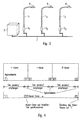
- FIG. 5 schematically represents the forwarding of a forward telegram in a network, wherein the vertical axis represents the time (in transmission and reception cycles), while the horizontal axis indicates the distance of the telegram from the place of origin. This distance is given in so-called.
- Logical repeater stages and corresponds to the number of repetitions of a reception of the telegram in a cycle and the forwarding in the immediately following cycle.
- a double arrow corresponds to the event that a telegram is sent to the network, while a circle represents that a subscriber is ready to receive.
- the network coupler NK sends the telegram intended for the subscriber 5, which is received simultaneously by the adjacent subscriber 1.
- the subscriber 1 in the cycle 1 sends the telegram one more time into the power grid, this now being received by the adjacent subscriber 2. This also sends the telegram in the next cycle 3 in the network. At this time, both the subscriber 1 and the subscriber 3 will be the one sent by the subscriber 2 Receive telegram. However, since the subscriber 1 recognizes that he has already forwarded this telegram to an earlier point in time, the telegram is forwarded in the subsequent cycle 3 exclusively by the subscriber 3, the subscriber 1 preferably suppresses a further transmission. This forwarding of the telegram finally continues until the telegram has arrived at the addressed subscriber 5 - represented by the triangle.
- Essential for the illustrated transmission method is that the participants connected via a power network have a common time frame for sending telegrams.
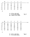
- a synchronization can be done for example by monitoring the zero crossing of the mains voltage and by a telegram itself, as for example in FIG. 6 is shown.
- a telegram is fed into the network, which - as described above - propagates across the network and thereby ensures synchronization of all participants to the network coupler NK.
- the synchronization is additionally improved in that the synchronization telegram is sent by the network coupler NK and the other participants each in two consecutive cycles.
- FIG. 7 now represents the propagation of a forward telegram and the feedback on a backward telegram, with all telegrams are repeated once to increase the transmission reliability.
- the network coupler NK sends a system message, which is directed to the subscriber 3 and prompts the latter to report an operating information.
- the forward telegram propagates so that during cycle 2 it is fed by the subscriber 2 into the network and received by the subscriber 3, again represented by the triangle.
- this subscriber 3 does not forward the forward telegram in the subsequent cycles 3 and 4, but instead sends a backward telegram which is sent to the Network coupler NK is addressed and contains the corresponding information.
- This backward telegram now propagates in all directions across the network until finally in the cycle 5 it is repeated by the first subscriber and thus received by the network coupler NK.
- the network coupler NK could already have sent another forward telegram because, due to the division of a cycle into the three channels, the forward and backward telegrams can run independently in different directions of transfer. This example thus illustrates that by dividing a transmit and receive cycle into three independent channels, data throughput can be increased.
- FIG. 8 finally shows a case in which the subscriber 4 sends an I-telegram due to an extraordinary event, which is transmitted independently of the indicated forward or backward telegrams to the network coupler NK in the manner described above.
- the data traffic just described by means of powerline communication takes place only between a network coupler and connected via a power grid lights.
- the other data transfers, however, are made by other communication techniques, which are not further explained below.
- the lights To address each of the individual lights individually or in groups, the lights have an operating address, which is divided into a corresponding group and individual address. In particular, this operating address may contain information about the geographical location of the luminaire.
- the lights of the outdoor lighting system can be displayed on a screen of the central server 3 in a graphical interface.
- the states of the individual luminaires can be displayed, for example their current brightness status or other information concerning the functionality of the individual luminaires.
- the presentation on a graphical user interface offers the possibility of addressing a specific part of the luminaires in a particularly simple and descriptive manner in order to convey individual commands to them.
- the desired lights or the corresponding area with the help of an input device - for example, a mouse - be marked.
- the within the marked area lying lights then automatically receive the desired instruction.
- the operation of the outdoor lighting system can be controlled in a particularly simple manner.
- each luminaire contains a suitable GPS receiver which permits an accurate determination of the position. This data can be reported back to the central server 3 or the maintenance center 4 via the various communication levels.
- the lights L - as in Fig. 2 shown - can be connected to a suitable GPS device 7 so that, for example, during installation, the corresponding location data from the light L can be stored.
- the location data stored in the lights L can also be used in a further inventive function of the lights L beyond. They have the ability to operate autonomously to some degree if they do not receive orders. This is made possible by the lights L having a memory in which the last received brightness commands are stored. These commands represent an action list, which is independently executed by a light L, if no new commands are received.
- the lights L include an internal clock, which ensures the timely execution of the action list, so that a light L, for example, in the evening at 20:00 clock turns on and off in the morning at 7:00 clock again. The synchronization of the internal clock can be done, for example, with the help of transmitted over the power network time data.
- the lights L can also have one in the Fig. 2 and 3 illustrated light sensor 8 whose input signal is taken into account in the brightness control of the lights L.
- the detected by the light sensors 8 data can also be transmitted in the context of a cyclic polling to the central server 3 in order to be able to take into account appropriate information for controlling the system at a central location.
- the lights L may also contain other sensors for detecting environmental parameters, such as temperature or the like.
- the in the Fig. 2 and 3 The sensor shown can generally be provided for the detection of environmental parameters, which are then taken into account in the execution of the commands.
- the sensor may also be used to detect the temperature or the presence of fog.
- a tilt sensor which can be used to determine whether the luminaire has been damaged or tilted due to external influences, for example an accident or the like.
- the action list for the previously described free-running function of the lights L is - as described - created by the fact that the lights L store the last commands received during normal operation.
- the freewheeling function can also be selectively used in that the lights L at the beginning of operation once a corresponding action list is transmitted. Subsequently, however, no further commands are made.
- the lamps L then work independently until they contain new commands at some point later.
- the storage of a corresponding action list can alternatively also take place via a powerline interface via which, for example, a laptop 9 or the like is connected.
- the lights L can be programmed independently of an outdoor lighting system and then work independently.
- the outdoor lighting system according to the invention is thus characterized by the diverse functionality of the individual lights, which can work largely independently under consideration of corresponding environmental parameters, but at the same time are also suitable for extensive data exchange with other lights or a central control unit.
- the repeater function of the luminaires enables reliable data transfer over the power network even over long distances, without the need for additional data lines.
Landscapes
- Engineering & Computer Science (AREA)
- Computer Networks & Wireless Communication (AREA)
- Signal Processing (AREA)
- Power Engineering (AREA)
- Circuit Arrangement For Electric Light Sources In General (AREA)
- Selective Calling Equipment (AREA)
- Control Of Eletrric Generators (AREA)
- Supply And Distribution Of Alternating Current (AREA)
- Remote Monitoring And Control Of Power-Distribution Networks (AREA)
- Train Traffic Observation, Control, And Security (AREA)
- Cable Transmission Systems, Equalization Of Radio And Reduction Of Echo (AREA)
- Laying Of Electric Cables Or Lines Outside (AREA)
Applications Claiming Priority (3)
| Application Number | Priority Date | Filing Date | Title |
|---|---|---|---|
| DE10128258A DE10128258A1 (de) | 2001-06-12 | 2001-06-12 | Powerline-Steuersystem |
| EP06015367A EP1717927B1 (fr) | 2001-06-12 | 2002-05-22 | Système de commande par ligne de tension |
| EP02750966A EP1483819B1 (fr) | 2001-06-12 | 2002-05-22 | Systeme de commande pour ligne secteur |
Related Parent Applications (2)
| Application Number | Title | Priority Date | Filing Date |
|---|---|---|---|
| EP02750966.0 Division | 2002-05-22 | ||
| EP06015367.3 Division | 2006-07-24 |
Publications (2)
| Publication Number | Publication Date |
|---|---|
| EP2302761A1 true EP2302761A1 (fr) | 2011-03-30 |
| EP2302761B1 EP2302761B1 (fr) | 2012-05-09 |
Family
ID=7687894
Family Applications (3)
| Application Number | Title | Priority Date | Filing Date |
|---|---|---|---|
| EP10183876A Expired - Lifetime EP2302761B1 (fr) | 2001-06-12 | 2002-05-22 | Système de commande de communications de réseau électrique |
| EP02750966A Expired - Lifetime EP1483819B1 (fr) | 2001-06-12 | 2002-05-22 | Systeme de commande pour ligne secteur |
| EP06015367A Expired - Lifetime EP1717927B1 (fr) | 2001-06-12 | 2002-05-22 | Système de commande par ligne de tension |
Family Applications After (2)
| Application Number | Title | Priority Date | Filing Date |
|---|---|---|---|
| EP02750966A Expired - Lifetime EP1483819B1 (fr) | 2001-06-12 | 2002-05-22 | Systeme de commande pour ligne secteur |
| EP06015367A Expired - Lifetime EP1717927B1 (fr) | 2001-06-12 | 2002-05-22 | Système de commande par ligne de tension |
Country Status (9)
| Country | Link |
|---|---|
| EP (3) | EP2302761B1 (fr) |
| AT (2) | ATE336821T1 (fr) |
| AU (1) | AU2002348766A1 (fr) |
| DE (2) | DE10128258A1 (fr) |
| DK (1) | DK1483819T3 (fr) |
| ES (1) | ES2271303T3 (fr) |
| NO (1) | NO326002B1 (fr) |
| PL (2) | PL207134B1 (fr) |
| WO (1) | WO2002101904A2 (fr) |
Families Citing this family (18)
| Publication number | Priority date | Publication date | Assignee | Title |
|---|---|---|---|---|
| JP3947895B2 (ja) * | 2000-02-24 | 2007-07-25 | 株式会社日立製作所 | 照明装置用点灯装置 |
| DE102004042200B4 (de) * | 2004-09-01 | 2007-04-19 | Legrand-Bticino Gmbh | Astronomische Schaltuhr mit automatischer Parametrierung |
| DE102005029728B4 (de) * | 2005-06-24 | 2007-06-06 | Baumeister, Jörg | Anordnung zur Steuerung der Straßenbeleuchtung |
| FI122992B (fi) * | 2009-11-05 | 2012-09-28 | Teclux Oy | Ulkovalaisu |
| PL390613A1 (pl) | 2010-03-04 | 2011-09-12 | Lars Co. K. Łagutko, A. Roman, J. Belino-Studziński Spółka Jawna | Sposób sterowania urządzeniami elektrycznymi, w szczególności lampami oświetleniowym, system sterowania urządzeniami elektrycznymi, w szczególności lampami oświetleniowym, sposób sterowania lampami oświetleniowym oraz lampa oświetleniowa |
| DE102010054784A1 (de) * | 2010-08-31 | 2012-03-01 | Cp Electronics Gmbh | Leuchtensystem |
| RU2489787C2 (ru) * | 2010-10-22 | 2013-08-10 | Общество с ограниченной ответственностью "Мастер МАКСИМУС" | Автоматизированная система мониторинга и управления освещением городов и автомобильных дорог |
| RU2474030C2 (ru) * | 2011-03-28 | 2013-01-27 | Открытое акционерное общество ОАО "Орбита" | Способ и система для управления электрическим оборудованием, в частности системой освещения |
| SK6029Y1 (sk) * | 2011-04-08 | 2012-03-02 | Jozef Sedlak | Involvement of programmable electronic ballast to supply lines for light sources |
| DE102012007497A1 (de) | 2012-04-17 | 2013-10-17 | Axel R. Hidde | Netzübertragungssystem mit Steuerung, Leitung und Empfänger |
| DE102012008215B4 (de) | 2012-04-18 | 2019-06-13 | Heribert Oechsler | Vorrichtung zur Realisierung einer Referenzuhr mit selbsttätiger Anbindung der internen Systemzeit an die Erdrotation |
| AT513542B1 (de) | 2012-11-15 | 2014-07-15 | Fronius Int Gmbh | Verfahren und Anordnung zur Datenkommunikation zwischen einem Wechselrichter und einer Netzüberwachungseinheit |
| US10231316B2 (en) | 2013-02-01 | 2019-03-12 | Philips Lighting Holding B.V. | Communication via a power waveform |
| DE102014111711B4 (de) | 2014-08-15 | 2026-01-15 | Tilo Könnecke | Steuerung der Leistungsaufnahme von elektrischen Verbrauchern im Außenbereich |
| DE102016207142B4 (de) * | 2016-04-27 | 2025-09-25 | Tridonic Gmbh & Co Kg | Nutzung von Rundsteuersignalen zur Zeitbestimmung in einem Beleuchtungssystem |
| DE102016217747B4 (de) | 2016-09-16 | 2024-02-22 | Tridonic Gmbh & Co Kg | Verfahren zur bidirektionalen kommunikation mittelsphasenschnittmodulation einer ac-versorgungsspannung sowieentsprechend ausgestaltetes betriebsgerät, steuergerät undsystem |
| US11483912B2 (en) * | 2018-05-18 | 2022-10-25 | Selc Ireland Ltd | Global positioning systems (GPS) registration tool (GRT) and related systems, methods and computer program products |
| DE102019131848A1 (de) | 2019-11-25 | 2021-05-27 | Beckhoff Automation Gmbh | Verfahren zum Betreiben eines Geräts, Gerät und System |
Citations (10)
| Publication number | Priority date | Publication date | Assignee | Title |
|---|---|---|---|---|
| EP0200016A2 (fr) | 1985-05-02 | 1986-11-05 | ABBPATENT GmbH | Procédé de transmission d'informations sur des réseaux d'alimentation en énergie électrique |
| DE4001265A1 (de) | 1990-01-18 | 1991-07-25 | Waldsee Electronic Gmbh | Verfahren und einrichtung zum empfang digitaler informationen ueber stromversorgungsnetze |
| DE4001266A1 (de) | 1990-01-18 | 1991-07-25 | Waldsee Electronic Gmbh | Verfahren und sendeeinrichtung zur uebertragung digitaler informationen ueber stromversorgungsnetze |
| EP0634842A2 (fr) | 1993-07-13 | 1995-01-18 | ABBPATENT GmbH | Procédé et dispositif de transmission bidirectionelle résistant aux perturbations pour réseaux d'alimentation électrique |
| US5461608A (en) * | 1993-06-30 | 1995-10-24 | Nec Corporation | Ring network with temporary master node for collecting data from slave nodes during failure |
| US5559377A (en) * | 1989-04-28 | 1996-09-24 | Abraham; Charles | Transformer coupler for communication over various lines |
| US5818725A (en) * | 1993-08-11 | 1998-10-06 | First Pacific Networks | System for utility demand monitoring and control |
| US5986539A (en) * | 1998-06-08 | 1999-11-16 | Ultracision, Inc. | Hafe-duplex two-wire DC power-line communication system |
| US6229432B1 (en) * | 1997-10-30 | 2001-05-08 | Duane Patrick Fridley | Intelligent transceiver module particularly suited for power line control systems |
| US6388399B1 (en) * | 1998-05-18 | 2002-05-14 | Leviton Manufacturing Co., Inc. | Network based electrical control system with distributed sensing and control |
Family Cites Families (9)
| Publication number | Priority date | Publication date | Assignee | Title |
|---|---|---|---|---|
| US4427968A (en) * | 1981-04-09 | 1984-01-24 | Westinghouse Electric Corp. | Distribution network communication system with flexible message routes |
| DE4418315C2 (de) * | 1994-05-26 | 1998-02-26 | L & R Losse Und Ramscheid Date | Verfahren und Schaltungsvorrichtung zur Reduzierung des Energieverbrauchs von Straßenbeleuchtungsnetzen |
| DK0775380T3 (da) * | 1994-08-10 | 1999-06-14 | Siemens Ag | Fjernstyringssystem med dataoverføring via afskærmningen af energioverføringskabler |
| DE4438901A1 (de) * | 1994-10-31 | 1996-05-02 | Setup Elektrotechnik Gmbh | Verfahren zur Leistungssteuerung von mehreren an eine Niedervolt-Wechselspannung-Zweidrahtleitung angeschlossenen Verbrauchern |
| DE29608623U1 (de) * | 1996-05-11 | 1996-08-01 | Insta Elektro GmbH & Co KG, 58511 Lüdenscheid | Anordnung zur Erzeugung von Lichtszenen |
| DE19653306C2 (de) * | 1996-12-20 | 2001-06-13 | Insta Elektro Gmbh & Co Kg | Verfahren für eine elektronische Jalousie-, Rolladen-, Markisensteuerung oder dergleichen |
| DE19731150A1 (de) * | 1997-07-21 | 1999-02-25 | Elektrobau Oschatz Gmbh & Co K | Verfahren und Schaltungsanordnung zum Betreiben und Überwachen diskontinuierlich betriebener elektrischer Verbraucher über Starkstromleitungen |
| ATE263445T1 (de) * | 1999-06-08 | 2004-04-15 | Lempi S A | System und verfahren zur fernverwaltung von einer strassenbeleuchtungsanlage, und mittel für die inbetriebnahme dieses verfahrens |
| FR2805355B1 (fr) * | 2000-02-22 | 2002-05-03 | L2G | Dispositif de commande perfectionnee d'une alimentation electrique, notamment pour candelabres d'eclairage public |
-
2001
- 2001-06-12 DE DE10128258A patent/DE10128258A1/de not_active Withdrawn
-
2002
- 2002-05-22 WO PCT/EP2002/005623 patent/WO2002101904A2/fr not_active Ceased
- 2002-05-22 PL PL385449A patent/PL207134B1/pl unknown
- 2002-05-22 AT AT02750966T patent/ATE336821T1/de active
- 2002-05-22 EP EP10183876A patent/EP2302761B1/fr not_active Expired - Lifetime
- 2002-05-22 PL PL372830A patent/PL207017B1/pl unknown
- 2002-05-22 DK DK02750966T patent/DK1483819T3/da active
- 2002-05-22 EP EP02750966A patent/EP1483819B1/fr not_active Expired - Lifetime
- 2002-05-22 AU AU2002348766A patent/AU2002348766A1/en not_active Abandoned
- 2002-05-22 AT AT10183876T patent/ATE557462T1/de active
- 2002-05-22 EP EP06015367A patent/EP1717927B1/fr not_active Expired - Lifetime
- 2002-05-22 DE DE50207889T patent/DE50207889D1/de not_active Expired - Lifetime
- 2002-05-22 ES ES02750966T patent/ES2271303T3/es not_active Expired - Lifetime
-
2003
- 2003-12-11 NO NO20035520A patent/NO326002B1/no not_active IP Right Cessation
Patent Citations (10)
| Publication number | Priority date | Publication date | Assignee | Title |
|---|---|---|---|---|
| EP0200016A2 (fr) | 1985-05-02 | 1986-11-05 | ABBPATENT GmbH | Procédé de transmission d'informations sur des réseaux d'alimentation en énergie électrique |
| US5559377A (en) * | 1989-04-28 | 1996-09-24 | Abraham; Charles | Transformer coupler for communication over various lines |
| DE4001265A1 (de) | 1990-01-18 | 1991-07-25 | Waldsee Electronic Gmbh | Verfahren und einrichtung zum empfang digitaler informationen ueber stromversorgungsnetze |
| DE4001266A1 (de) | 1990-01-18 | 1991-07-25 | Waldsee Electronic Gmbh | Verfahren und sendeeinrichtung zur uebertragung digitaler informationen ueber stromversorgungsnetze |
| US5461608A (en) * | 1993-06-30 | 1995-10-24 | Nec Corporation | Ring network with temporary master node for collecting data from slave nodes during failure |
| EP0634842A2 (fr) | 1993-07-13 | 1995-01-18 | ABBPATENT GmbH | Procédé et dispositif de transmission bidirectionelle résistant aux perturbations pour réseaux d'alimentation électrique |
| US5818725A (en) * | 1993-08-11 | 1998-10-06 | First Pacific Networks | System for utility demand monitoring and control |
| US6229432B1 (en) * | 1997-10-30 | 2001-05-08 | Duane Patrick Fridley | Intelligent transceiver module particularly suited for power line control systems |
| US6388399B1 (en) * | 1998-05-18 | 2002-05-14 | Leviton Manufacturing Co., Inc. | Network based electrical control system with distributed sensing and control |
| US5986539A (en) * | 1998-06-08 | 1999-11-16 | Ultracision, Inc. | Hafe-duplex two-wire DC power-line communication system |
Also Published As
| Publication number | Publication date |
|---|---|
| PL207134B1 (pl) | 2010-11-30 |
| NO326002B1 (no) | 2008-09-01 |
| EP1717927B1 (fr) | 2012-07-04 |
| EP1717927A2 (fr) | 2006-11-02 |
| ES2271303T3 (es) | 2007-04-16 |
| DE50207889D1 (de) | 2006-09-28 |
| ATE557462T1 (de) | 2012-05-15 |
| DE10128258A1 (de) | 2002-12-19 |
| WO2002101904A3 (fr) | 2004-09-23 |
| NO20035520D0 (no) | 2003-12-11 |
| PL372830A1 (en) | 2005-08-08 |
| ATE336821T1 (de) | 2006-09-15 |
| WO2002101904A2 (fr) | 2002-12-19 |
| AU2002348766A1 (en) | 2002-12-23 |
| EP1483819A2 (fr) | 2004-12-08 |
| DK1483819T3 (da) | 2006-12-18 |
| EP1483819B1 (fr) | 2006-08-16 |
| EP2302761B1 (fr) | 2012-05-09 |
| PL207017B1 (pl) | 2010-10-29 |
| EP1717927A3 (fr) | 2011-03-16 |
Similar Documents
| Publication | Publication Date | Title |
|---|---|---|
| EP2302761B1 (fr) | Système de commande de communications de réseau électrique | |
| DE602004011201T2 (de) | Paketkommunikation zwischen einer sammeleinheit und einer vielzahl von steuervorrichtungen über die stromversorgung | |
| EP1064759B1 (fr) | Procede de mise en service d'un systeme bus et systeme bus en question | |
| DE68925085T2 (de) | Laststeuerungssystem | |
| DE102007044816B3 (de) | Verfahren zum Betrieb eines Bussystems | |
| DE69526932T2 (de) | Kommunikation ueber eine serienleitung | |
| DE102009005431A1 (de) | Buskoppler mit Netzteil | |
| DE3611949C2 (fr) | ||
| EP0192120B1 (fr) | Système et dispositif de transmission de données pour commande à distance | |
| EP0813324A1 (fr) | Bus de données en série et son utilisation | |
| DE102010052661B3 (de) | Kommunikationssystem zur Steuerung von elektrischen Lasten | |
| DE102020119124A1 (de) | System und Verfahren zum Herstellen einer Datenverbindung zwischen einer Master-Einheit und zumindest einer Device-Einheit | |
| EP3251469A1 (fr) | Procédé pour faire fonctionner des appareils dans un système d'éclairage | |
| DE4447559A1 (de) | Verfahren für den Betrieb einer Aufladesteuervorrichtung für eine Speicherheizgeräteanlage | |
| DE69406796T2 (de) | Mikroprozessoreinrichtung zur überwachung von beleuchtungselementen und verfahren mit solch einer einrichtung | |
| DE3211020C1 (de) | Übertragungs-Einrichtung zur Datenübermittlung zwischen einer Steuerzentrale und mehreren Regel- oder Steuergeräten eines Gebäudes | |
| EP2957148B1 (fr) | Procédé et systém pour commander des charges connectées a une ligne de bus | |
| DE19917063B4 (de) | Drahtloses Datenübertragungssystem zur Ankopplung eines mobilen Bedien- und Anzeigegerätes an einen Steuerbus | |
| DE19927869C1 (de) | Elektroinstallationseinrichtung für Gebäude | |
| EP2941101B1 (fr) | Système d'éclairage doté d'une pluralité d'éclairages couplés et de détecteurs de présence | |
| EP0738033B1 (fr) | Installation de télécommande centralisée | |
| DE3241438C2 (de) | Verfahren zum Steuern transportabler Lichtzeichenanlagen | |
| CH689929A5 (de) | Verfahren zur Informationsübertragung in Rundsteuersystemen. | |
| EP0121666B1 (fr) | Méthode et dispositif pour la surveillance d'amplificateurs intermédiaires | |
| EP2891933A1 (fr) | Unité de réglage pour un système de chauffage ayant un mode d'économie d'énergie et de commande de communication et procédé de commande ou de réglage d'une unité de réglage |
Legal Events
| Date | Code | Title | Description |
|---|---|---|---|
| PUAI | Public reference made under article 153(3) epc to a published international application that has entered the european phase |
Free format text: ORIGINAL CODE: 0009012 |
|
| AC | Divisional application: reference to earlier application |
Ref document number: 1717927 Country of ref document: EP Kind code of ref document: P Ref document number: 1483819 Country of ref document: EP Kind code of ref document: P |
|
| AK | Designated contracting states |
Kind code of ref document: A1 Designated state(s): AT BE CH CY DE DK ES FI FR GB GR IE IT LI LU MC NL PT SE TR |
|
| 17P | Request for examination filed |
Effective date: 20110825 |
|
| GRAP | Despatch of communication of intention to grant a patent |
Free format text: ORIGINAL CODE: EPIDOSNIGR1 |
|
| RIC1 | Information provided on ipc code assigned before grant |
Ipc: H05B 37/02 20060101ALI20111017BHEP Ipc: H02J 13/00 20060101AFI20111017BHEP Ipc: H04B 3/54 20060101ALI20111017BHEP Ipc: H04L 12/403 20060101ALI20111017BHEP Ipc: H04L 12/28 20060101ALI20111017BHEP Ipc: H05B 37/03 20060101ALI20111017BHEP Ipc: H05B 41/392 20060101ALI20111017BHEP |
|
| RIN1 | Information on inventor provided before grant (corrected) |
Inventor name: KUFFER, ALOIS Inventor name: WITTMANN, GERHARD |
|
| GRAS | Grant fee paid |
Free format text: ORIGINAL CODE: EPIDOSNIGR3 |
|
| GRAA | (expected) grant |
Free format text: ORIGINAL CODE: 0009210 |
|
| AC | Divisional application: reference to earlier application |
Ref document number: 1483819 Country of ref document: EP Kind code of ref document: P Ref document number: 1717927 Country of ref document: EP Kind code of ref document: P |
|
| AK | Designated contracting states |
Kind code of ref document: B1 Designated state(s): AT BE CH CY DE DK ES FI FR GB GR IE IT LI LU MC NL PT SE TR |
|
| REG | Reference to a national code |
Ref country code: GB Ref legal event code: FG4D Free format text: NOT ENGLISH |
|
| REG | Reference to a national code |
Ref country code: AT Ref legal event code: REF Ref document number: 557462 Country of ref document: AT Kind code of ref document: T Effective date: 20120515 Ref country code: CH Ref legal event code: EP Ref country code: CH Ref legal event code: NV Representative=s name: RIEDERER HASLER & PARTNER PATENTANWAELTE AG |
|
| REG | Reference to a national code |
Ref country code: IE Ref legal event code: FG4D Free format text: LANGUAGE OF EP DOCUMENT: GERMAN |
|
| REG | Reference to a national code |
Ref country code: DE Ref legal event code: R096 Ref document number: 50215479 Country of ref document: DE Effective date: 20120705 |
|
| REG | Reference to a national code |
Ref country code: NL Ref legal event code: T3 |
|
| PG25 | Lapsed in a contracting state [announced via postgrant information from national office to epo] |
Ref country code: FI Free format text: LAPSE BECAUSE OF FAILURE TO SUBMIT A TRANSLATION OF THE DESCRIPTION OR TO PAY THE FEE WITHIN THE PRESCRIBED TIME-LIMIT Effective date: 20120509 Ref country code: CY Free format text: LAPSE BECAUSE OF FAILURE TO SUBMIT A TRANSLATION OF THE DESCRIPTION OR TO PAY THE FEE WITHIN THE PRESCRIBED TIME-LIMIT Effective date: 20120509 Ref country code: SE Free format text: LAPSE BECAUSE OF FAILURE TO SUBMIT A TRANSLATION OF THE DESCRIPTION OR TO PAY THE FEE WITHIN THE PRESCRIBED TIME-LIMIT Effective date: 20120509 |
|
| BERE | Be: lapsed |
Owner name: ZUMTOBEL LIGHTING GMBH Effective date: 20120531 |
|
| PG25 | Lapsed in a contracting state [announced via postgrant information from national office to epo] |
Ref country code: PT Free format text: LAPSE BECAUSE OF FAILURE TO SUBMIT A TRANSLATION OF THE DESCRIPTION OR TO PAY THE FEE WITHIN THE PRESCRIBED TIME-LIMIT Effective date: 20120910 Ref country code: GR Free format text: LAPSE BECAUSE OF FAILURE TO SUBMIT A TRANSLATION OF THE DESCRIPTION OR TO PAY THE FEE WITHIN THE PRESCRIBED TIME-LIMIT Effective date: 20120810 |
|
| PG25 | Lapsed in a contracting state [announced via postgrant information from national office to epo] |
Ref country code: MC Free format text: LAPSE BECAUSE OF NON-PAYMENT OF DUE FEES Effective date: 20120531 |
|
| PG25 | Lapsed in a contracting state [announced via postgrant information from national office to epo] |
Ref country code: DK Free format text: LAPSE BECAUSE OF FAILURE TO SUBMIT A TRANSLATION OF THE DESCRIPTION OR TO PAY THE FEE WITHIN THE PRESCRIBED TIME-LIMIT Effective date: 20120509 |
|
| REG | Reference to a national code |
Ref country code: IE Ref legal event code: MM4A |
|
| PG25 | Lapsed in a contracting state [announced via postgrant information from national office to epo] |
Ref country code: BE Free format text: LAPSE BECAUSE OF NON-PAYMENT OF DUE FEES Effective date: 20120531 |
|
| PLBE | No opposition filed within time limit |
Free format text: ORIGINAL CODE: 0009261 |
|
| STAA | Information on the status of an ep patent application or granted ep patent |
Free format text: STATUS: NO OPPOSITION FILED WITHIN TIME LIMIT |
|
| 26N | No opposition filed |
Effective date: 20130212 |
|
| PG25 | Lapsed in a contracting state [announced via postgrant information from national office to epo] |
Ref country code: IE Free format text: LAPSE BECAUSE OF NON-PAYMENT OF DUE FEES Effective date: 20120522 Ref country code: ES Free format text: LAPSE BECAUSE OF FAILURE TO SUBMIT A TRANSLATION OF THE DESCRIPTION OR TO PAY THE FEE WITHIN THE PRESCRIBED TIME-LIMIT Effective date: 20120820 |
|
| REG | Reference to a national code |
Ref country code: DE Ref legal event code: R097 Ref document number: 50215479 Country of ref document: DE Effective date: 20130212 |
|
| PG25 | Lapsed in a contracting state [announced via postgrant information from national office to epo] |
Ref country code: TR Free format text: LAPSE BECAUSE OF FAILURE TO SUBMIT A TRANSLATION OF THE DESCRIPTION OR TO PAY THE FEE WITHIN THE PRESCRIBED TIME-LIMIT Effective date: 20120509 |
|
| PG25 | Lapsed in a contracting state [announced via postgrant information from national office to epo] |
Ref country code: LU Free format text: LAPSE BECAUSE OF NON-PAYMENT OF DUE FEES Effective date: 20120522 |
|
| PGFP | Annual fee paid to national office [announced via postgrant information from national office to epo] |
Ref country code: IT Payment date: 20140526 Year of fee payment: 13 Ref country code: NL Payment date: 20140523 Year of fee payment: 13 |
|
| PGFP | Annual fee paid to national office [announced via postgrant information from national office to epo] |
Ref country code: CH Payment date: 20150526 Year of fee payment: 14 |
|
| PGFP | Annual fee paid to national office [announced via postgrant information from national office to epo] |
Ref country code: AT Payment date: 20150528 Year of fee payment: 14 |
|
| PG25 | Lapsed in a contracting state [announced via postgrant information from national office to epo] |
Ref country code: IT Free format text: LAPSE BECAUSE OF NON-PAYMENT OF DUE FEES Effective date: 20150522 |
|
| REG | Reference to a national code |
Ref country code: NL Ref legal event code: MM Effective date: 20150601 |
|
| PG25 | Lapsed in a contracting state [announced via postgrant information from national office to epo] |
Ref country code: NL Free format text: LAPSE BECAUSE OF NON-PAYMENT OF DUE FEES Effective date: 20150601 |
|
| REG | Reference to a national code |
Ref country code: FR Ref legal event code: PLFP Year of fee payment: 15 |
|
| REG | Reference to a national code |
Ref country code: CH Ref legal event code: PL |
|
| REG | Reference to a national code |
Ref country code: AT Ref legal event code: MM01 Ref document number: 557462 Country of ref document: AT Kind code of ref document: T Effective date: 20160522 |
|
| PG25 | Lapsed in a contracting state [announced via postgrant information from national office to epo] |
Ref country code: LI Free format text: LAPSE BECAUSE OF NON-PAYMENT OF DUE FEES Effective date: 20160531 Ref country code: CH Free format text: LAPSE BECAUSE OF NON-PAYMENT OF DUE FEES Effective date: 20160531 |
|
| PG25 | Lapsed in a contracting state [announced via postgrant information from national office to epo] |
Ref country code: AT Free format text: LAPSE BECAUSE OF NON-PAYMENT OF DUE FEES Effective date: 20160522 |
|
| REG | Reference to a national code |
Ref country code: FR Ref legal event code: PLFP Year of fee payment: 16 |
|
| REG | Reference to a national code |
Ref country code: FR Ref legal event code: PLFP Year of fee payment: 17 |
|
| REG | Reference to a national code |
Ref country code: DE Ref legal event code: R084 Ref document number: 50215479 Country of ref document: DE |
|
| PGFP | Annual fee paid to national office [announced via postgrant information from national office to epo] |
Ref country code: FR Payment date: 20190527 Year of fee payment: 18 |
|
| PGFP | Annual fee paid to national office [announced via postgrant information from national office to epo] |
Ref country code: DE Payment date: 20200529 Year of fee payment: 19 |
|
| GBPC | Gb: european patent ceased through non-payment of renewal fee |
Effective date: 20200522 |
|
| PG25 | Lapsed in a contracting state [announced via postgrant information from national office to epo] |
Ref country code: GB Free format text: LAPSE BECAUSE OF NON-PAYMENT OF DUE FEES Effective date: 20200522 Ref country code: FR Free format text: LAPSE BECAUSE OF NON-PAYMENT OF DUE FEES Effective date: 20200531 |
|
| REG | Reference to a national code |
Ref country code: DE Ref legal event code: R119 Ref document number: 50215479 Country of ref document: DE |
|
| PG25 | Lapsed in a contracting state [announced via postgrant information from national office to epo] |
Ref country code: DE Free format text: LAPSE BECAUSE OF NON-PAYMENT OF DUE FEES Effective date: 20211201 |