EP2302765A2 - Extern drehender Mechanismus durch Versatz des äußeren Drehelektromaschinenantriebs - Google Patents
Extern drehender Mechanismus durch Versatz des äußeren Drehelektromaschinenantriebs Download PDFInfo
- Publication number
- EP2302765A2 EP2302765A2 EP10179612A EP10179612A EP2302765A2 EP 2302765 A2 EP2302765 A2 EP 2302765A2 EP 10179612 A EP10179612 A EP 10179612A EP 10179612 A EP10179612 A EP 10179612A EP 2302765 A2 EP2302765 A2 EP 2302765A2
- Authority
- EP
- European Patent Office
- Prior art keywords
- electrical machine
- ring type
- wheel
- offset
- running wheel
- Prior art date
- Legal status (The legal status is an assumption and is not a legal conclusion. Google has not performed a legal analysis and makes no representation as to the accuracy of the status listed.)
- Withdrawn
Links
- 230000007246 mechanism Effects 0.000 title claims abstract description 163
- 238000009434 installation Methods 0.000 claims abstract description 14
- 230000005540 biological transmission Effects 0.000 claims description 85
- 230000003068 static effect Effects 0.000 claims description 34
- 230000008878 coupling Effects 0.000 claims description 28
- 238000010168 coupling process Methods 0.000 claims description 28
- 238000005859 coupling reaction Methods 0.000 claims description 28
- 230000000149 penetrating effect Effects 0.000 claims description 9
- WABPQHHGFIMREM-UHFFFAOYSA-N lead(0) Chemical compound [Pb] WABPQHHGFIMREM-UHFFFAOYSA-N 0.000 claims description 6
- 238000000034 method Methods 0.000 claims description 6
- 238000001816 cooling Methods 0.000 claims description 2
- 230000001419 dependent effect Effects 0.000 claims description 2
- 230000001360 synchronised effect Effects 0.000 claims description 2
- 238000009423 ventilation Methods 0.000 claims description 2
- 238000010586 diagram Methods 0.000 description 2
Images


Classifications
-
- F—MECHANICAL ENGINEERING; LIGHTING; HEATING; WEAPONS; BLASTING
- F16—ENGINEERING ELEMENTS AND UNITS; GENERAL MEASURES FOR PRODUCING AND MAINTAINING EFFECTIVE FUNCTIONING OF MACHINES OR INSTALLATIONS; THERMAL INSULATION IN GENERAL
- F16H—GEARING
- F16H3/00—Toothed gearings for conveying rotary motion with variable gear ratio or for reversing rotary motion
-
- B—PERFORMING OPERATIONS; TRANSPORTING
- B60—VEHICLES IN GENERAL
- B60K—ARRANGEMENT OR MOUNTING OF PROPULSION UNITS OR OF TRANSMISSIONS IN VEHICLES; ARRANGEMENT OR MOUNTING OF PLURAL DIVERSE PRIME-MOVERS IN VEHICLES; AUXILIARY DRIVES FOR VEHICLES; INSTRUMENTATION OR DASHBOARDS FOR VEHICLES; ARRANGEMENTS IN CONNECTION WITH COOLING, AIR INTAKE, GAS EXHAUST OR FUEL SUPPLY OF PROPULSION UNITS IN VEHICLES
- B60K17/00—Arrangement or mounting of transmissions in vehicles
- B60K17/04—Arrangement or mounting of transmissions in vehicles characterised by arrangement, location or kind of gearing
- B60K17/043—Transmission unit disposed in on near the vehicle wheel, or between the differential gear unit and the wheel
- B60K17/046—Transmission unit disposed in on near the vehicle wheel, or between the differential gear unit and the wheel with planetary gearing having orbital motion
-
- B—PERFORMING OPERATIONS; TRANSPORTING
- B60—VEHICLES IN GENERAL
- B60K—ARRANGEMENT OR MOUNTING OF PROPULSION UNITS OR OF TRANSMISSIONS IN VEHICLES; ARRANGEMENT OR MOUNTING OF PLURAL DIVERSE PRIME-MOVERS IN VEHICLES; AUXILIARY DRIVES FOR VEHICLES; INSTRUMENTATION OR DASHBOARDS FOR VEHICLES; ARRANGEMENTS IN CONNECTION WITH COOLING, AIR INTAKE, GAS EXHAUST OR FUEL SUPPLY OF PROPULSION UNITS IN VEHICLES
- B60K7/00—Disposition of motor in, or adjacent to, traction wheel
- B60K7/0007—Disposition of motor in, or adjacent to, traction wheel the motor being electric
-
- B—PERFORMING OPERATIONS; TRANSPORTING
- B60—VEHICLES IN GENERAL
- B60L—PROPULSION OF ELECTRICALLY-PROPELLED VEHICLES; SUPPLYING ELECTRIC POWER FOR AUXILIARY EQUIPMENT OF ELECTRICALLY-PROPELLED VEHICLES; ELECTRODYNAMIC BRAKE SYSTEMS FOR VEHICLES IN GENERAL; MAGNETIC SUSPENSION OR LEVITATION FOR VEHICLES; MONITORING OPERATING VARIABLES OF ELECTRICALLY-PROPELLED VEHICLES; ELECTRIC SAFETY DEVICES FOR ELECTRICALLY-PROPELLED VEHICLES
- B60L15/00—Methods, circuits, or devices for controlling the traction-motor speed of electrically-propelled vehicles
- B60L15/20—Methods, circuits, or devices for controlling the traction-motor speed of electrically-propelled vehicles for control of the vehicle or its driving motor to achieve a desired performance, e.g. speed, torque, programmed variation of speed
- B60L15/2054—Methods, circuits, or devices for controlling the traction-motor speed of electrically-propelled vehicles for control of the vehicle or its driving motor to achieve a desired performance, e.g. speed, torque, programmed variation of speed by controlling transmissions or clutches
-
- H—ELECTRICITY
- H02—GENERATION; CONVERSION OR DISTRIBUTION OF ELECTRIC POWER
- H02K—DYNAMO-ELECTRIC MACHINES
- H02K41/00—Propulsion systems in which a rigid body is moved along a path due to dynamo-electric interaction between the body and a magnetic field travelling along the path
- H02K41/06—Rolling motors, i.e. motors having the rotor axis parallel to the stator axis and following a circular path as the rotor rolls around the inside or outside of the stator ; Nutating motors, i.e. having the rotor axis parallel to the stator axis inclined with respect to the stator axis and performing a nutational movement as the rotor rolls on the stator
-
- H—ELECTRICITY
- H02—GENERATION; CONVERSION OR DISTRIBUTION OF ELECTRIC POWER
- H02K—DYNAMO-ELECTRIC MACHINES
- H02K7/00—Arrangements for handling mechanical energy structurally associated with dynamo-electric machines, e.g. structural association with mechanical driving motors or auxiliary dynamo-electric machines
- H02K7/10—Structural association with clutches, brakes, gears, pulleys or mechanical starters
- H02K7/116—Structural association with clutches, brakes, gears, pulleys or mechanical starters with gears
-
- B—PERFORMING OPERATIONS; TRANSPORTING
- B60—VEHICLES IN GENERAL
- B60K—ARRANGEMENT OR MOUNTING OF PROPULSION UNITS OR OF TRANSMISSIONS IN VEHICLES; ARRANGEMENT OR MOUNTING OF PLURAL DIVERSE PRIME-MOVERS IN VEHICLES; AUXILIARY DRIVES FOR VEHICLES; INSTRUMENTATION OR DASHBOARDS FOR VEHICLES; ARRANGEMENTS IN CONNECTION WITH COOLING, AIR INTAKE, GAS EXHAUST OR FUEL SUPPLY OF PROPULSION UNITS IN VEHICLES
- B60K7/00—Disposition of motor in, or adjacent to, traction wheel
- B60K2007/0038—Disposition of motor in, or adjacent to, traction wheel the motor moving together with the wheel axle
-
- B—PERFORMING OPERATIONS; TRANSPORTING
- B60—VEHICLES IN GENERAL
- B60K—ARRANGEMENT OR MOUNTING OF PROPULSION UNITS OR OF TRANSMISSIONS IN VEHICLES; ARRANGEMENT OR MOUNTING OF PLURAL DIVERSE PRIME-MOVERS IN VEHICLES; AUXILIARY DRIVES FOR VEHICLES; INSTRUMENTATION OR DASHBOARDS FOR VEHICLES; ARRANGEMENTS IN CONNECTION WITH COOLING, AIR INTAKE, GAS EXHAUST OR FUEL SUPPLY OF PROPULSION UNITS IN VEHICLES
- B60K7/00—Disposition of motor in, or adjacent to, traction wheel
- B60K2007/0061—Disposition of motor in, or adjacent to, traction wheel the motor axle being parallel to the wheel axle
-
- B—PERFORMING OPERATIONS; TRANSPORTING
- B60—VEHICLES IN GENERAL
- B60L—PROPULSION OF ELECTRICALLY-PROPELLED VEHICLES; SUPPLYING ELECTRIC POWER FOR AUXILIARY EQUIPMENT OF ELECTRICALLY-PROPELLED VEHICLES; ELECTRODYNAMIC BRAKE SYSTEMS FOR VEHICLES IN GENERAL; MAGNETIC SUSPENSION OR LEVITATION FOR VEHICLES; MONITORING OPERATING VARIABLES OF ELECTRICALLY-PROPELLED VEHICLES; ELECTRIC SAFETY DEVICES FOR ELECTRICALLY-PROPELLED VEHICLES
- B60L2220/00—Electrical machine types; Structures or applications thereof
- B60L2220/40—Electrical machine applications
- B60L2220/44—Wheel Hub motors, i.e. integrated in the wheel hub
-
- B—PERFORMING OPERATIONS; TRANSPORTING
- B60—VEHICLES IN GENERAL
- B60L—PROPULSION OF ELECTRICALLY-PROPELLED VEHICLES; SUPPLYING ELECTRIC POWER FOR AUXILIARY EQUIPMENT OF ELECTRICALLY-PROPELLED VEHICLES; ELECTRODYNAMIC BRAKE SYSTEMS FOR VEHICLES IN GENERAL; MAGNETIC SUSPENSION OR LEVITATION FOR VEHICLES; MONITORING OPERATING VARIABLES OF ELECTRICALLY-PROPELLED VEHICLES; ELECTRIC SAFETY DEVICES FOR ELECTRICALLY-PROPELLED VEHICLES
- B60L2220/00—Electrical machine types; Structures or applications thereof
- B60L2220/50—Structural details of electrical machines
-
- B—PERFORMING OPERATIONS; TRANSPORTING
- B60—VEHICLES IN GENERAL
- B60L—PROPULSION OF ELECTRICALLY-PROPELLED VEHICLES; SUPPLYING ELECTRIC POWER FOR AUXILIARY EQUIPMENT OF ELECTRICALLY-PROPELLED VEHICLES; ELECTRODYNAMIC BRAKE SYSTEMS FOR VEHICLES IN GENERAL; MAGNETIC SUSPENSION OR LEVITATION FOR VEHICLES; MONITORING OPERATING VARIABLES OF ELECTRICALLY-PROPELLED VEHICLES; ELECTRIC SAFETY DEVICES FOR ELECTRICALLY-PROPELLED VEHICLES
- B60L2240/00—Control parameters of input or output; Target parameters
- B60L2240/40—Drive Train control parameters
- B60L2240/48—Drive Train control parameters related to transmissions
- B60L2240/486—Operating parameters
-
- B—PERFORMING OPERATIONS; TRANSPORTING
- B60—VEHICLES IN GENERAL
- B60Y—INDEXING SCHEME RELATING TO ASPECTS CROSS-CUTTING VEHICLE TECHNOLOGY
- B60Y2200/00—Type of vehicle
- B60Y2200/10—Road Vehicles
- B60Y2200/13—Bicycles; Tricycles
-
- Y—GENERAL TAGGING OF NEW TECHNOLOGICAL DEVELOPMENTS; GENERAL TAGGING OF CROSS-SECTIONAL TECHNOLOGIES SPANNING OVER SEVERAL SECTIONS OF THE IPC; TECHNICAL SUBJECTS COVERED BY FORMER USPC CROSS-REFERENCE ART COLLECTIONS [XRACs] AND DIGESTS
- Y02—TECHNOLOGIES OR APPLICATIONS FOR MITIGATION OR ADAPTATION AGAINST CLIMATE CHANGE
- Y02T—CLIMATE CHANGE MITIGATION TECHNOLOGIES RELATED TO TRANSPORTATION
- Y02T10/00—Road transport of goods or passengers
- Y02T10/60—Other road transportation technologies with climate change mitigation effect
- Y02T10/64—Electric machine technologies in electromobility
-
- Y—GENERAL TAGGING OF NEW TECHNOLOGICAL DEVELOPMENTS; GENERAL TAGGING OF CROSS-SECTIONAL TECHNOLOGIES SPANNING OVER SEVERAL SECTIONS OF THE IPC; TECHNICAL SUBJECTS COVERED BY FORMER USPC CROSS-REFERENCE ART COLLECTIONS [XRACs] AND DIGESTS
- Y02—TECHNOLOGIES OR APPLICATIONS FOR MITIGATION OR ADAPTATION AGAINST CLIMATE CHANGE
- Y02T—CLIMATE CHANGE MITIGATION TECHNOLOGIES RELATED TO TRANSPORTATION
- Y02T10/00—Road transport of goods or passengers
- Y02T10/60—Other road transportation technologies with climate change mitigation effect
- Y02T10/72—Electric energy management in electromobility
-
- Y—GENERAL TAGGING OF NEW TECHNOLOGICAL DEVELOPMENTS; GENERAL TAGGING OF CROSS-SECTIONAL TECHNOLOGIES SPANNING OVER SEVERAL SECTIONS OF THE IPC; TECHNICAL SUBJECTS COVERED BY FORMER USPC CROSS-REFERENCE ART COLLECTIONS [XRACs] AND DIGESTS
- Y10—TECHNICAL SUBJECTS COVERED BY FORMER USPC
- Y10T—TECHNICAL SUBJECTS COVERED BY FORMER US CLASSIFICATION
- Y10T74/00—Machine element or mechanism
- Y10T74/19—Gearing
- Y10T74/19642—Directly cooperating gears
- Y10T74/19647—Parallel axes or shafts
Definitions
- An externally rotating mechanism through offset outer rotating electrical machine drive is constituted of an externally rotating mechanism, offset mechanism, outer rotating electrical machine and transmission.
- the externally rotating mechanism is equipped with a wheel hub structure; and installed with a fixed axle to facilitate rotation of the wheel hub.
- An offset mechanism is further installed inside the wheel hub.
- the radial offset mechanism is installed with one or more extension arm/s for deployment of one or more rotary arbors and to become an offset outer rotating electrical machine with the fixed axle rotating the wheel hub.
- a running wheel is coaxially installed with the outer rotating electrical machine rotary housing which includes gear or friction wheel to couple with the ring type inner running wheel installed inside the wheel hub in order to enable a running function between the outer rotating electrical machine rotary parts of the outer rotating electrical machine and the externally rotating mechanism.
- the running wheels of the individual outer rotating electrical machine rotary part together couple with the ring type inner running wheel installed inside the wheel hub in order to jointly drive the externally rotating mechanism to improve power.
- FIG. 14 is an operational front sectional view of the present invention in FIG. 13 .
- FIG. 16 is the operational front sectional view of the present invention in FIG. 15 .
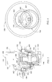
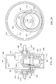
- FIG. 19 is the first operational side sectional view of the present invention showing the surrounding of the housing of the outer rotating electrical machine rotary part of the outer rotating electrical machine (300) installed with ring type outer running wheel (413); and ring type inner running wheel (412) installed in the externally rotating mechanism (100); and running wheels installed in the wheel hub (101) and on one side of the outer rotating electrical machine housing.
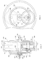
- FIG. 20 is the operational front sectional view of the present invention in FIG. 19 .
- the offset mechanism (200) is a U-shape structure.
- the offset mechanism (200) is for combining with the fixed axle (104). Both ends of its extension arm (105) permanently combine with both ends of the electrical machine arbor (301) of the fixed electrical machine static part (311) of the outer rotating electrical machine (300).
- a running wheel (403) is installed on one side of the electrical machine rotary part (312) of the outer rotating electrical machine (300) that is performing outside rotation, and a ring type inner running wheel (402) which is using the fixed axle (104) as its axis is installed on the same side inside the wheel hub (101).
- the two running wheels couple and drive to form the transmission.
- a ring type outer running wheel (413) is coaxially installed on the exterior of the electrical machine rotary part (312) for coupling with the ring type inner running wheel (412) installed in the axial inner ring space of the externally rotating mechanism in order to form the transmission between the electrical machine rotary part (312) of the outer rotating electrical machine and the externally rotating mechanism (100).
- the aforementioned running wheel (403) and ring type inner running wheel (402) as well as the ring type inner running wheel (412) and the coaxially installed ring type outer running wheel (413) are composed of gears and friction wheels.
- the numbers of driving steps of the aforementioned transmission is/are one or more.
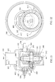
- FIG. 22 is the operational front sectional view of the present invention in FIG. 21 .
- FIG. 24 is the operational front sectional view of the present invention in FIG. 23 .
- the offset structure (200) has a one-piece fixed axle (104) penetrating through the axle holes (102) installed on both sides and at the center of the wheel disc, and a section of the axle that combines with the offset structure (200) when the fixed axle (104) passes through the wheel hub (101) interior.
- the extension arm (105) of the offset structure (200) is to permanently combine with both ends of the electrical machine arbor (301) of the electrical machine static part (311) of the outer rotating electrical machine (300) so that the driving axis of the outer rotating electrical machine rotary part (312) and the fixed axle (104) driving the wheel hub (101) become offset and uncoaxial to each other.
- a running wheel (403) is installed on one side of the electrical machine rotary part (312).
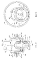
- FIG. 26 is an operational front sectional view of the present invention in FIG. 25 .
- the offset mechanism (200) is a U-shape structure.
- the offset mechanism (200) is for combining with the fixed axle (104). Both ends of its extension arm (105) permanently combine with both ends of the electrical machine arbor (301) of the fixed electrical machine static part (311) of the outer rotating electrical machine (300).
- Running wheels (403) are installed on both sides of the electrical machine rotary part (312) of the outer rotating electrical machine (300) that is performing outside rotation, and ring type inner running wheels (402) which are using the fixed axle (104) as their axis are installed on the both sides of the wheel hub (101) interior.
- the two running wheels couple and drive to form the transmission.
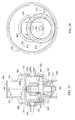
- FIG. 28 is the operational front sectional view of the present invention in FIG 27 .
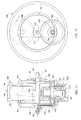
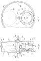
- a ring type outer running wheel (413) is coaxially installed on the exterior of the electrical machine rotary part (312) for coupling with the ring type inner running wheel (412) installed in the axial inner ring space of the externally rotating mechanism (100) in order to form the transmission between the electrical machine rotary part (312) of the outer rotating electrical machine and the externally rotating mechanism.
- the aforementioned running wheel (403) and ring type inner running wheel (402) as well as the ring type inner running wheel (412) and the coaxially installed ring type outer running wheel (413) are composed of gears and friction wheels.
- the numbers of driving steps of the aforementioned transmission is/are one or more steps.
- FIG 29 is the third operational side sectional view of the present invention showing the surrounding of the housing of the outer rotating electrical machine rotary part of the outer rotating electrical machine (300) installed with ring type outer running wheel (413); and ring type inner running wheel (412) installed in the externally rotating mechanism (100); and running wheels installed in the wheel hub (10) and on both sides of the outer rotating electrical machine housing.
- FIG. 30 is the operational front sectional view of the present invention in FIG. 29 .
Landscapes
- Engineering & Computer Science (AREA)
- Mechanical Engineering (AREA)
- Transportation (AREA)
- Chemical & Material Sciences (AREA)
- Combustion & Propulsion (AREA)
- Power Engineering (AREA)
- General Engineering & Computer Science (AREA)
- Physics & Mathematics (AREA)
- Electromagnetism (AREA)
- Arrangement Or Mounting Of Propulsion Units For Vehicles (AREA)
- Friction Gearing (AREA)
- Connection Of Motors, Electrical Generators, Mechanical Devices, And The Like (AREA)
- Retarders (AREA)
- Gear Transmission (AREA)
- Motorcycle And Bicycle Frame (AREA)
Applications Claiming Priority (1)
| Application Number | Priority Date | Filing Date | Title |
|---|---|---|---|
| US12/585,804 US8409042B2 (en) | 2009-09-25 | 2009-09-25 | Externally rotating mechanism through offset outer rotating electrical machine drive |
Publications (2)
| Publication Number | Publication Date |
|---|---|
| EP2302765A2 true EP2302765A2 (de) | 2011-03-30 |
| EP2302765A3 EP2302765A3 (de) | 2014-06-18 |
Family
ID=42935549
Family Applications (1)
| Application Number | Title | Priority Date | Filing Date |
|---|---|---|---|
| EP10179612.6A Withdrawn EP2302765A3 (de) | 2009-09-25 | 2010-09-24 | Extern drehender Mechanismus durch Versatz des äußeren Drehelektromaschinenantriebs |
Country Status (6)
| Country | Link |
|---|---|
| US (1) | US8409042B2 (de) |
| EP (1) | EP2302765A3 (de) |
| JP (1) | JP5746842B2 (de) |
| KR (1) | KR101897274B1 (de) |
| CN (1) | CN102035291B (de) |
| TW (1) | TWI488412B (de) |
Cited By (2)
| Publication number | Priority date | Publication date | Assignee | Title |
|---|---|---|---|---|
| CN102946167A (zh) * | 2012-11-12 | 2013-02-27 | 南京纳帝机电技术有限公司 | 电动车用行星传动组合电机 |
| EP3947047A4 (de) * | 2019-03-24 | 2022-12-14 | TVS Motor Company Limited | Fahrzeug mit elektrischem antriebsmotor |
Families Citing this family (5)
| Publication number | Priority date | Publication date | Assignee | Title |
|---|---|---|---|---|
| JP5751623B2 (ja) * | 2011-05-18 | 2015-07-22 | セイコーインスツル株式会社 | 小型発電装置、及び携帯型電子機器 |
| US20130285515A1 (en) * | 2012-04-26 | 2013-10-31 | Tai-Her Yang | External rotation type power generation device having biased power generator |
| KR20180113578A (ko) * | 2016-02-15 | 2018-10-16 | 인디애나 유니버시티 리서치 앤드 테크놀로지 코포레이션 | 롤링 엘리먼트를 갖는 높은 토크 밀도 전기 모터/발전기 |
| WO2022065106A1 (ja) * | 2020-09-25 | 2022-03-31 | 株式会社クボタ | 回転電機 |
| JP7339229B2 (ja) * | 2020-11-16 | 2023-09-05 | トヨタ自動車株式会社 | 電動車両 |
Citations (7)
| Publication number | Priority date | Publication date | Assignee | Title |
|---|---|---|---|---|
| GB2161436A (en) * | 1984-07-04 | 1986-01-15 | Dennis Vincent Wrigley | Motorised golf trolley wheel |
| US6722459B1 (en) * | 1999-07-13 | 2004-04-20 | Zf Friedrichshafen Ag | Axle having a bridge arranged underneath the wheel axle |
| DE102004030317A1 (de) * | 2004-06-23 | 2006-01-12 | Abb Patent Gmbh | Antriebseinheit für einen Regelantrieb |
| US20070257570A1 (en) * | 2003-08-22 | 2007-11-08 | Magnet-Motor Gesellschaft Fuer Magnetmotorische Te | Electric Driving Unit for a Vehicle |
| CN201038911Y (zh) * | 2006-11-21 | 2008-03-19 | 綦学尧 | 外转子行星齿轮减速电动机 |
| CN201038912Y (zh) * | 2006-12-06 | 2008-03-19 | 綦学尧 | 外转子少齿差行星齿轮减速电动机 |
| CN101286681A (zh) * | 2008-02-05 | 2008-10-15 | 杜文达 | 电动式磁力差速驱动器 |
Family Cites Families (10)
| Publication number | Priority date | Publication date | Assignee | Title |
|---|---|---|---|---|
| US3812928A (en) * | 1972-05-12 | 1974-05-28 | Allis Chalmers | Electric powered wheel |
| JPH05340449A (ja) * | 1992-04-08 | 1993-12-21 | Nissan Motor Co Ltd | 電気自動車用動力伝達装置 |
| US6321863B1 (en) * | 2000-06-26 | 2001-11-27 | Mac Brushless Motor Company | Hub motor for a wheeled vehicle |
| US7475611B2 (en) * | 2002-03-29 | 2009-01-13 | Tai-Her Yang | Device for externally rotary drive of offset motor |
| JP2004090822A (ja) | 2002-09-02 | 2004-03-25 | Toyota Motor Corp | 車両用モータ配備車輪装置 |
| JP2006282158A (ja) | 2005-03-08 | 2006-10-19 | Honda Motor Co Ltd | 車両用ホイール駆動装置 |
| JP4820189B2 (ja) * | 2006-03-09 | 2011-11-24 | 本田技研工業株式会社 | 車両用ホイール駆動装置の配置構造 |
| JP4724075B2 (ja) * | 2006-08-29 | 2011-07-13 | 本田技研工業株式会社 | ホイール回転装置 |
| DE102006052253B3 (de) * | 2006-11-03 | 2008-07-10 | Zf Friedrichshafen Ag | Verstellantrieb zur örtlichen Verstellung einer Fahrwerkskomponente |
| DE102007016218B4 (de) * | 2007-04-04 | 2016-06-09 | Audi Ag | Hybrid-Antriebsvorrichtung für Kraftfahrzeuge |
-
2009
- 2009-09-25 US US12/585,804 patent/US8409042B2/en not_active Expired - Fee Related
-
2010
- 2010-09-20 CN CN201010287582.8A patent/CN102035291B/zh not_active Expired - Fee Related
- 2010-09-24 TW TW099132398A patent/TWI488412B/zh not_active IP Right Cessation
- 2010-09-24 EP EP10179612.6A patent/EP2302765A3/de not_active Withdrawn
- 2010-09-24 KR KR1020100092841A patent/KR101897274B1/ko not_active Expired - Fee Related
- 2010-09-24 JP JP2010213428A patent/JP5746842B2/ja not_active Expired - Fee Related
Patent Citations (7)
| Publication number | Priority date | Publication date | Assignee | Title |
|---|---|---|---|---|
| GB2161436A (en) * | 1984-07-04 | 1986-01-15 | Dennis Vincent Wrigley | Motorised golf trolley wheel |
| US6722459B1 (en) * | 1999-07-13 | 2004-04-20 | Zf Friedrichshafen Ag | Axle having a bridge arranged underneath the wheel axle |
| US20070257570A1 (en) * | 2003-08-22 | 2007-11-08 | Magnet-Motor Gesellschaft Fuer Magnetmotorische Te | Electric Driving Unit for a Vehicle |
| DE102004030317A1 (de) * | 2004-06-23 | 2006-01-12 | Abb Patent Gmbh | Antriebseinheit für einen Regelantrieb |
| CN201038911Y (zh) * | 2006-11-21 | 2008-03-19 | 綦学尧 | 外转子行星齿轮减速电动机 |
| CN201038912Y (zh) * | 2006-12-06 | 2008-03-19 | 綦学尧 | 外转子少齿差行星齿轮减速电动机 |
| CN101286681A (zh) * | 2008-02-05 | 2008-10-15 | 杜文达 | 电动式磁力差速驱动器 |
Cited By (2)
| Publication number | Priority date | Publication date | Assignee | Title |
|---|---|---|---|---|
| CN102946167A (zh) * | 2012-11-12 | 2013-02-27 | 南京纳帝机电技术有限公司 | 电动车用行星传动组合电机 |
| EP3947047A4 (de) * | 2019-03-24 | 2022-12-14 | TVS Motor Company Limited | Fahrzeug mit elektrischem antriebsmotor |
Also Published As
| Publication number | Publication date |
|---|---|
| KR101897274B1 (ko) | 2018-09-11 |
| KR20110033799A (ko) | 2011-03-31 |
| US20110072926A1 (en) | 2011-03-31 |
| TWI488412B (zh) | 2015-06-11 |
| EP2302765A3 (de) | 2014-06-18 |
| US8409042B2 (en) | 2013-04-02 |
| JP5746842B2 (ja) | 2015-07-08 |
| JP2011069493A (ja) | 2011-04-07 |
| TW201112587A (en) | 2011-04-01 |
| CN102035291B (zh) | 2015-12-09 |
| CN102035291A (zh) | 2011-04-27 |
Similar Documents
| Publication | Publication Date | Title |
|---|---|---|
| EP2302765A2 (de) | Extern drehender Mechanismus durch Versatz des äußeren Drehelektromaschinenantriebs | |
| US10396626B2 (en) | Electric machine | |
| CN111120583B (zh) | 减速装置及机电设备 | |
| US20140128194A1 (en) | Drive unit mounted close to the wheel for a motor vehicle | |
| JP6114323B2 (ja) | 自転車駆動装置 | |
| CN101370706A (zh) | 电动自行车轮毂 | |
| JP2000035092A (ja) | 動力車のための駆動装置 | |
| CN102282364A (zh) | 用于风能设备的发电机装置 | |
| JP2020029959A (ja) | 減速装置及び電気機器 | |
| JP2003094957A (ja) | 電動ホイールモータ | |
| AU2015201365A1 (en) | Double acting generator | |
| US20140066248A1 (en) | Drive device for vehicle with electric motor | |
| CN109314438A (zh) | 无铁心电动机 | |
| CN204190553U (zh) | 电动自行车用可变减速比的轮毂电机 | |
| JP2008215550A (ja) | 歯車変速機構及び車輪駆動装置 | |
| US10024390B2 (en) | Pancake motor | |
| JP2019035419A (ja) | 車両用駆動装置、および車両用駆動装置の設計方法 | |
| CA2813767A1 (en) | External rotation type power generation device having biased power generator | |
| JP2007336783A (ja) | 発電機及び風力発電方法並びに水力発電方法 | |
| CN104617724A (zh) | 一种同心同向双轴无刷电动机 | |
| KR100218288B1 (ko) | 엇회전식 축류팬 | |
| CN102959280B (zh) | 具有自有通风装置的电动发电机 | |
| JP2018153052A (ja) | 電動自転車に用いる電動モータ | |
| GB2341731A (en) | Motor/gear drive arrangement of the planetary type | |
| KR100769877B1 (ko) | 일체형 동력전달축을 구비한 전동기 |
Legal Events
| Date | Code | Title | Description |
|---|---|---|---|
| PUAI | Public reference made under article 153(3) epc to a published international application that has entered the european phase |
Free format text: ORIGINAL CODE: 0009012 |
|
| AK | Designated contracting states |
Kind code of ref document: A2 Designated state(s): AL AT BE BG CH CY CZ DE DK EE ES FI FR GB GR HR HU IE IS IT LI LT LU LV MC MK MT NL NO PL PT RO SE SI SK SM TR |
|
| AX | Request for extension of the european patent |
Extension state: BA ME RS |
|
| PUAL | Search report despatched |
Free format text: ORIGINAL CODE: 0009013 |
|
| AK | Designated contracting states |
Kind code of ref document: A3 Designated state(s): AL AT BE BG CH CY CZ DE DK EE ES FI FR GB GR HR HU IE IS IT LI LT LU LV MC MK MT NL NO PL PT RO SE SI SK SM TR |
|
| AX | Request for extension of the european patent |
Extension state: BA ME RS |
|
| RIC1 | Information provided on ipc code assigned before grant |
Ipc: B60K 17/04 20060101ALI20140513BHEP Ipc: H02K 7/10 20060101ALI20140513BHEP Ipc: H02K 7/116 20060101AFI20140513BHEP |
|
| 17P | Request for examination filed |
Effective date: 20141117 |
|
| RBV | Designated contracting states (corrected) |
Designated state(s): AL AT BE BG CH CY CZ DE DK EE ES FI FR GB GR HR HU IE IS IT LI LT LU LV MC MK MT NL NO PL PT RO SE SI SK SM TR |
|
| 17Q | First examination report despatched |
Effective date: 20151203 |
|
| STAA | Information on the status of an ep patent application or granted ep patent |
Free format text: STATUS: EXAMINATION IS IN PROGRESS |
|
| STAA | Information on the status of an ep patent application or granted ep patent |
Free format text: STATUS: THE APPLICATION HAS BEEN WITHDRAWN |
|
| 18W | Application withdrawn |
Effective date: 20201021 |