EP2304193B1 - Joint d'étanchéité pour contenir des écoulements de fuite entre des composants voisins de turbomachines, en particulier de turbines à gaz - Google Patents
Joint d'étanchéité pour contenir des écoulements de fuite entre des composants voisins de turbomachines, en particulier de turbines à gaz Download PDFInfo
- Publication number
- EP2304193B1 EP2304193B1 EP09772337.3A EP09772337A EP2304193B1 EP 2304193 B1 EP2304193 B1 EP 2304193B1 EP 09772337 A EP09772337 A EP 09772337A EP 2304193 B1 EP2304193 B1 EP 2304193B1
- Authority
- EP
- European Patent Office
- Prior art keywords
- sealing
- sealing element
- seal
- section
- cover
- Prior art date
- Legal status (The legal status is an assumption and is not a legal conclusion. Google has not performed a legal analysis and makes no representation as to the accuracy of the status listed.)
- Not-in-force
Links
Images

Classifications
-
- F—MECHANICAL ENGINEERING; LIGHTING; HEATING; WEAPONS; BLASTING
- F16—ENGINEERING ELEMENTS AND UNITS; GENERAL MEASURES FOR PRODUCING AND MAINTAINING EFFECTIVE FUNCTIONING OF MACHINES OR INSTALLATIONS; THERMAL INSULATION IN GENERAL
- F16J—PISTONS; CYLINDERS; SEALINGS
- F16J9/00—Piston-rings, e.g. non-metallic piston-rings, seats therefor; Ring sealings of similar construction
- F16J9/12—Details
- F16J9/20—Rings with special cross-section; Oil-scraping rings
-
- F—MECHANICAL ENGINEERING; LIGHTING; HEATING; WEAPONS; BLASTING
- F01—MACHINES OR ENGINES IN GENERAL; ENGINE PLANTS IN GENERAL; STEAM ENGINES
- F01D—NON-POSITIVE DISPLACEMENT MACHINES OR ENGINES, e.g. STEAM TURBINES
- F01D11/00—Preventing or minimising internal leakage of working-fluid, e.g. between stages
- F01D11/005—Sealing means between non relatively rotating elements
-
- F—MECHANICAL ENGINEERING; LIGHTING; HEATING; WEAPONS; BLASTING
- F16—ENGINEERING ELEMENTS AND UNITS; GENERAL MEASURES FOR PRODUCING AND MAINTAINING EFFECTIVE FUNCTIONING OF MACHINES OR INSTALLATIONS; THERMAL INSULATION IN GENERAL
- F16J—PISTONS; CYLINDERS; SEALINGS
- F16J15/00—Sealings
- F16J15/02—Sealings between relatively-stationary surfaces
- F16J15/06—Sealings between relatively-stationary surfaces with solid packing compressed between sealing surfaces
- F16J15/08—Sealings between relatively-stationary surfaces with solid packing compressed between sealing surfaces with exclusively metal packing
- F16J15/0887—Sealings between relatively-stationary surfaces with solid packing compressed between sealing surfaces with exclusively metal packing the sealing effect being obtained by elastic deformation of the packing
- F16J15/0893—Sealings between relatively-stationary surfaces with solid packing compressed between sealing surfaces with exclusively metal packing the sealing effect being obtained by elastic deformation of the packing the packing having a hollow profile
-
- F—MECHANICAL ENGINEERING; LIGHTING; HEATING; WEAPONS; BLASTING
- F16—ENGINEERING ELEMENTS AND UNITS; GENERAL MEASURES FOR PRODUCING AND MAINTAINING EFFECTIVE FUNCTIONING OF MACHINES OR INSTALLATIONS; THERMAL INSULATION IN GENERAL
- F16J—PISTONS; CYLINDERS; SEALINGS
- F16J9/00—Piston-rings, e.g. non-metallic piston-rings, seats therefor; Ring sealings of similar construction
- F16J9/12—Details
- F16J9/22—Rings for preventing wear of grooves or like seatings
-
- F—MECHANICAL ENGINEERING; LIGHTING; HEATING; WEAPONS; BLASTING
- F05—INDEXING SCHEMES RELATING TO ENGINES OR PUMPS IN VARIOUS SUBCLASSES OF CLASSES F01-F04
- F05D—INDEXING SCHEME FOR ASPECTS RELATING TO NON-POSITIVE-DISPLACEMENT MACHINES OR ENGINES, GAS-TURBINES OR JET-PROPULSION PLANTS
- F05D2230/00—Manufacture
- F05D2230/20—Manufacture essentially without removing material
- F05D2230/23—Manufacture essentially without removing material by permanently joining parts together
- F05D2230/232—Manufacture essentially without removing material by permanently joining parts together by welding
- F05D2230/237—Brazing
-
- F—MECHANICAL ENGINEERING; LIGHTING; HEATING; WEAPONS; BLASTING
- F05—INDEXING SCHEMES RELATING TO ENGINES OR PUMPS IN VARIOUS SUBCLASSES OF CLASSES F01-F04
- F05D—INDEXING SCHEME FOR ASPECTS RELATING TO NON-POSITIVE-DISPLACEMENT MACHINES OR ENGINES, GAS-TURBINES OR JET-PROPULSION PLANTS
- F05D2240/00—Components
- F05D2240/55—Seals
-
- F—MECHANICAL ENGINEERING; LIGHTING; HEATING; WEAPONS; BLASTING
- F05—INDEXING SCHEMES RELATING TO ENGINES OR PUMPS IN VARIOUS SUBCLASSES OF CLASSES F01-F04
- F05D—INDEXING SCHEME FOR ASPECTS RELATING TO NON-POSITIVE-DISPLACEMENT MACHINES OR ENGINES, GAS-TURBINES OR JET-PROPULSION PLANTS
- F05D2250/00—Geometry
- F05D2250/70—Shape
- F05D2250/71—Shape curved
- F05D2250/711—Shape curved convex
-
- F—MECHANICAL ENGINEERING; LIGHTING; HEATING; WEAPONS; BLASTING
- F05—INDEXING SCHEMES RELATING TO ENGINES OR PUMPS IN VARIOUS SUBCLASSES OF CLASSES F01-F04
- F05D—INDEXING SCHEME FOR ASPECTS RELATING TO NON-POSITIVE-DISPLACEMENT MACHINES OR ENGINES, GAS-TURBINES OR JET-PROPULSION PLANTS
- F05D2250/00—Geometry
- F05D2250/70—Shape
- F05D2250/71—Shape curved
- F05D2250/712—Shape curved concave
-
- F—MECHANICAL ENGINEERING; LIGHTING; HEATING; WEAPONS; BLASTING
- F23—COMBUSTION APPARATUS; COMBUSTION PROCESSES
- F23R—GENERATING COMBUSTION PRODUCTS OF HIGH PRESSURE OR HIGH VELOCITY, e.g. GAS-TURBINE COMBUSTION CHAMBERS
- F23R2900/00—Special features of, or arrangements for continuous combustion chambers; Combustion processes therefor
- F23R2900/00012—Details of sealing devices
Definitions
- the invention relates to a seal for containing leakage flows between adjacent components of turbomachines, in particular gas turbines, wherein the seal has an elongated, in at least one transverse direction elastically deformable, thin-walled sealing element, which has the shape of a curved band in cross-section.
- the gasket When installed, the gasket is biased in a space bounded by walls of the two components in the at least one transverse direction, such that the at least one transverse direction is perpendicular to two opposing sealing surfaces, one on a wall of one component and the other on a wall of the other component.
- Both in the cross-sectionally C-shaped sealing element and in the cross-sectionally E-shaped sealing element is located between the respective free ends of an opening which faces a high pressure side of the gap. Also in the sealing element having a U-shaped cross section in the middle part, there is an opening which faces the high-pressure side of the gap. This opening is located between the two outwardly bent round end portions of the sealing element.
- All of the aforementioned cross-sectional shapes of the sealing element of the known seal have in common that they each have two abutting the sealing surfaces of the components contact areas in the vicinity of the free ends of the sealing element and further having a voltage applied to the support wall support region, wherein the support region of the low pressure side of the gap is exposed.
- the sealing element of these known seals is arranged under prestress in the space between the two components, so that deforms at an example thermally induced extension of the gap perpendicular to the opposite sealing surfaces, the sealing element such that widens the respective opening, and the contact areas of the sealing element follow the moving away from each other sealing surfaces of the components. Conversely, in an example, also thermally induced narrowing of the gap perpendicular to the opposite sealing surfaces, the sealing element deformed such that the respective Narrowed opening and reduces the distance between the voltage applied to the sealing surfaces contact areas.
- the opening of the sealing element of the known seal facing the high pressure side of the gap and a support portion containing surface portion of the sealing element of the low pressure side of the gap is exposed, resulting from the pressure difference on the sealing element acting forces, on the one hand, the resulting by elastic deformation of the sealing element, the Strengthen contact areas on the sealing surfaces of the components pressing spring forces and on the other hand press the support area firmly against the support wall.
- the forces resulting from the pressure difference between the high-pressure side and the low-pressure side of the gap act in the same direction as the spring forces produced by elastic deformation of the sealing element.
- the contact areas of the sealing element are also pressed against the sealing surfaces of the components when the spring forces no longer act due to excessively large gap enlargement or fatigue of the sealing element due to constantly changing deformation of the sealing element.
- the elastic deformability of the sealing element due to the respective cross-sectional shape of the sealing element of the known seal, the elastic deformability of the sealing element, however, set narrow limits, so that they can bridge only those gaps that extend only slightly compared to an initial gap width.
- a seal with a one-piece sealing element whose cross-sectional shape is composed of a U-shaped central portion and two adjoining the U-shaped central portion end portions, which are bent around outwardly, is also from the EP 1 323 894 A2 known.
- This known seal is arranged in a cross-sectionally U-shaped groove which is arranged in one of two abutting components of a gas turbine.
- the sealing element lies with a support area located on the outside of the U-shaped central portion, on a support wall, which is one of two opposing walls of the U-shaped Bauteilnut.
- the components have two opposing sealing surfaces, one of which is located at the bottom of the U-shaped groove.
- the sealing element is biased in a space between the two components arranged so that the bent round end portions abut with their respective outer side on the opposite sealing surfaces of the components.
- the support wall opposite wall of the U-shaped Bauteilnut has a considerable distance from the bent end portions of the sealing element.
- the sealing element can move between the two opposite walls of the U-shaped groove in a degree that can lead to tilting of the sealing element when the components move accordingly.
- this seal is not suitable to maintain their sealing performance when forms a larger gap between the two components, because then the end portions of the sealing element no longer or not tight enough rest against the sealing surfaces of the components.
- a pressure differential seal having an annular seal member having in cross section the shape of a multi-arched band having a plurality of successive bends with alternating bends, each bend being the cross-sectional shape of an associated arcuate wall portion of the seal member.
- the sealing element has an "S" shape in cross section, having two successive oppositely curved wall sections joined together by a transverse wall section. Each of the curved wall sections is adjoined by an end section having the respective free end, which has in each case a bend whose convex outer side bears against a sealing surface of the respective component.
- the seal is arranged in an annular space between two concentrically arranged components under bias, wherein the two sealing surfaces of the components are aligned either axially or radially.
- the sealing element is elastically deformable perpendicular to the sealing surfaces, wherein it is stronger in this direction is elastically deformable than, for example, a cross-sectionally C-shaped sealing element, but in movements of the components parallel to their sealing surfaces, as well as a cross-sectionally C-shaped sealing element is exposed to the risk to change its position.
- the sealing element consists of a cross-sectionally S-shaped portion and a rectilinear portion which is connected by welding to one end of the S-shaped portion and serves to rotate the S-shaped portion of the annular sealing member prevent.
- the rectilinear section is the cross section of a planar ring.
- the sealing member has more than two consecutive curved wall portions and a rectilinear in cross-section end portion having a convex surface portion which bears against a sealing surface of the associated component.
- This embodiment has a high elastic deformability perpendicular to the parallel sealing surfaces of the components.
- this embodiment can preferably be used where larger movements of the components are to be expected perpendicular to their sealing surfaces.
- this embodiment of the known seal is also unfavorably loaded in a movement of the components parallel to their sealing surfaces, so that it may come as a result of such movements to an undesirable tilting or a change in position of the sealing element with adverse effects on the sealing performance.
- the FR 2 031 924 presents an annular sealing element of high elasticity, which should be particularly suitable for high pressure differences with simultaneously pronounced temperature changes. It consists of two thin-walled arched components of an elastic metal, preferably steel, whose central convex surface portions are fixedly connected to each other, so that form an X-shaped cross-section.
- the sealing member may comprise a soft metal casing which is slipped over the X-shaped spread legs at the opposite ends of the sealing member, respectively, to enhance gas tightness increase. In operation, the sealing element is compressed and presses with its legs resiliently against the adjacent surface portions of the components to be sealed.
- the pamphlets GB 732,020 and US 5 075 591 show compressible gaskets for sealing gas-filled pressure chambers, which are able to withstand high temperatures and are particularly suitable for use in internal combustion engines.
- a bandage of thin-walled, strip-shaped sealing elements lies in a groove between two components to be sealed, wherein it exceeds the groove depth by a certain amount.
- the strip-shaped sealing elements are bent one or more times and are in the operating condition under a bias applied by the components to be sealed. Gap deformations as a result of thermal expansion or other changes in the gap width give way elastically. However, the effective spring range is relatively limited.
- GB 2 303 888 has a strip seal for combustion chambers of gas turbine engines to the object.
- Each of the components to be sealed is provided opposite to a receiving groove for a flexible strip-shaped sealing element made of a metallic material.
- the sealing strip indicates its two opposite ends U-shaped cover elements. These cover elements are formed in the form and dimension complementary to the receiving grooves and even have a certain elasticity to automatically apply to the walls of the grooves. In this way, the sealing element can be fixed practically non-positively in the receiving groove. Relative movements of the components to be sealed and consequent changes in position of the grooves is able to follow the flexible sealing element, without the sealing effect is affected by leaks.
- annular seal in which the elastically deformable sealing element may be single or multi-layered and in cross-section either U-shaped with outwardly bent end portions ( Figures 2 . 3, 4 ) or E-shaped ( Figures 6, 10) with three successive curved wall sections and two end sections bent outwards.
- the sealing element may be subjected to a differential pressure, such that the outwardly bent end portions are pressed more strongly against the opposing sealing surfaces of the components.
- the multi-layer design has a higher strength than the single-layer design. Slots circumferentially spaced may be provided in one of the sheets of material of the sealing member to increase the flexibility of the sealing member. This seal is suitable for bridging relatively slightly in their width varying gaps between two components. But the sealing performance of this known seal is also at risk if the components move parallel to their sealing surfaces.
- double-E seals are known, which are composed of two in cross section E-shaped sealing elements, which are connected by a strip-shaped in cross-section cover strip by welding or soldering.
- This type of seal can as well as the single cross-sectionally E-shaped sealing element bridge larger gaps than the cross-sectionally C-shaped sealing element.
- the double-E seal is prone to less than the single-E seal at tilting or shifting parallel to the sealing surfaces directed relative movements of the components;
- larger relative movements of the components parallel to their sealing surfaces also affect the positional stability and wear resistance of the double-E seal, so that it can lead to failure of the double-E seal with larger relative movements of the components parallel to their sealing surfaces.
- the object of the invention is to develop the generic seal so that it is characterized by a high elastic deformability in a direction transverse to the sealing surfaces of the components direction and a high resistance to deformation and changes in position relative movements of the components parallel to their sealing surfaces and at a high wear resistance guarantees the longest possible satisfactory sealing performance.
- the integrity of the seal is ensured even with relatively large relative movements of the components.
- the seal of the invention has a high wear resistance and thus guarantees a consistently good sealing performance over a longer period.
- the gasket according to the invention can also be used at such locations of a gas turbine, where previously C-seals were used, which indeed have a good wear behavior, but only a low elastic compliance.
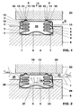
- a seal as in the FIGS. 1 to 4 is shown, has an elastically deformable, thin-walled, in cross-section the shape of a curved band comprising metal sealing element 1, which has two adjacent rows of successive curved wall sections 2, which are each interconnected by a transverse wall portion 3.
- metal sealing element 1 which has two adjacent rows of successive curved wall sections 2, which are each interconnected by a transverse wall portion 3.
- six curved wall sections 2 are present in each row, which are interconnected by a total of five transverse wall sections 3.
- This number of curved wall sections 2 in each row and the associated number of transverse wall sections 3 are only examples; they could also be larger or smaller, as they determine the desired extent of the elastic deformability of the sealing element 1.
- both rows of successive wall sections 2 and connecting them transverse wall sections 3 are arranged so that in each row all transverse wall sections 3 each intersect a common center plane E and the two center planes E, E are parallel to each other.
- bottom curved wall portion 2 of each row which, when the successive wall sections 2 are counted from bottom to top, can also be referred to as a "first" curved wall portion 2, each extending a wall portion 4, which extends at its end remote from the curved wall portion 2 end a weld 5 with one end of a band-shaped in cross-section, also thin-walled cover strip 6 made of metal is firmly connected.
- the wall sections 4 of the sealing element 1 by welding to the cover strip 6, they can be firmly connected to the cover strip 6 by brazing.
- the cover strip 6 is curved wave-shaped, that there are two in the lateral distance from each other located convex surface regions 7, each partially, preferably linearly, abut sealingly against a sealing surface 8 of a component 9.
- the cross-sectional shape of the cover strip 6 shown in the drawings is only an example; In other embodiments, the cover strip 6 in cross-section also be substantially straight and in this case can then be applied to the sealing surface 8
- Convex surface areas 7 of the cover strip 6 may be formed by beads.
- top curved wall portion 2 of each row which, when the successive wall sections 2 is counted from bottom to top, can also be referred to as a "last" curved wall portion 2, extends a cross-sectionally band-shaped end portion 10 which in the vicinity of its free end a Has convex surface portion 11 which rests tightly against the concave inner side of a respective bead 12, which is part of a cross-sectionally U-shaped, thin-walled cover 13 made of metal.
- the cover member 13 has two parallel, emanating from a base 14, in Fig. 1 downwardly facing legs 15, which define together with the base 14 a downwardly open space 16 in which the sealing element 1, as in the Figures 1 and 2 visible, partially recorded.
- the sealing member 1 and the cover member 13 are fixedly connected to each other by welding or brazing.
- the convex outside in the Figures 1 and 2 right raised bead 12, is a strip-shaped raised surface portion 17 on the side remote from the space 16 outside of the base 14 of the cover 13. This raised surface portion is located along a perpendicular to the plane extending, continuous seal line 18 close to the sealing surface 19 of another component 20 at , The seal line 18 is in Fig. 4 shown as a dashed line.
- the concave outside of the in the Figures 1 and 2 left bead 12 of the cover 13 is in a strip-shaped area on the outside of the base 14, a lateral distance from the in the Figures 1 and 2 right bead 12 has.
- the left-hand bead 12 has a plurality of longitudinally spaced openings 21, between which lie raised surface portions 22 which extend along an in-plane Fig. 4 dashed lines, interrupted by the opening 21 sealing line 23 against the sealing surface 19 of the component 20 tightly.
- the openings 21 are on the space 16 facing the inside of the base 14 of Abdecklementes 13 covered by the convex surface portion 11 of the base 14 and thus sealed to the space 16 through.
- Each aperture 21 provides a flow channel bounded by the sealing surface 19, the cover member 13 and the convex surface portion 11 of the sealing member 1 and having a space 24 enclosed between the sealing lines 18 and 23, the sealing surface 19 and the outside of the base 14 of the cover member the FIGS. 1, 2 and 4 connects to the left of the seal line 23 lying outer environment of the seal.
- FIG. 1 Right wall section 4 are provided at intervals from each other a plurality of openings 25.
- the openings 25 connect the inside of the seal lying space 16 with the in the FIGS. 1, 2 and 4 to the right of the seal line 18 lying outer environment of the seal.
- Fig. 3 there are a plurality of slots 26 in the legs 15 of the cover 13.
- the slots 26 extend from the free end of the legs 15 in the direction of the base 14 of the cover 13.
- the slots 26 allow the cover 13 in the Drawing plane of the Fig. 3 is elastically bendable.
- the seal is part of a seal assembly to which the two components 9 and 20 belong, the parallel sealing surfaces 8 and 19 facing each other.
- a cross-sectionally U-shaped groove 27 which is formed by two opposite walls 28 of the component 9 and the sealing surface 8.
- the gasket is disposed in the space defined by the opposing walls 28 and opposing sealing surfaces 8 and 19 of the components 9 and 20, respectively, which is part of a gap 29 of variable width between the components 9 and 20 in the illustrated embodiment has two spaced apart exits 30 and 31, between which the seal is arranged.
- the output 30 is the gap 29 with a gaseous medium Low pressure P low- containing area in conjunction, and via the output 31, the gap 29 is in communication with a gaseous medium of higher pressure P high- containing area.
- the object of the seal is to seal the two components 9 and 20 against each other by preventing leakage flow from the high-pressure region through the gap 29 to the lower region.
- the metal components 9 and 20 are exposed to different thermal loads, such as when they are parts of a combustion chamber and on the one hand are subjected to compressed cooling air for the combustion chamber and, on the other hand, hot combustion gases from the combustion chamber.
- thermal stress on the components 9 and 20 deformations occur that are expressed in relative movements of the components 9, 20 perpendicular to their sealing surfaces 8 and 19, but also in relative movements parallel to their sealing surfaces 8 and 19 respectively.
- the width of the gap 29 changes accordingly. Due to the geometry and the elastic material properties of the sealing element 1, the sealing element 1 is elastically deformable mainly in the transverse direction, that is, parallel to the center planes E, E.
- the sealing element 1 is shown in a partially compressed state, which also represents the installation state of the gasket before or after an operating cycle of the gas turbine.
- the legs 15 of the cover 13 project into the U-shaped groove 27, wherein they have a slight lateral play to the adjacent, opposing walls 28 of the component 9.
- the legs 15 of the cover 13 can therefore move parallel to the walls 28 and slightly perpendicular to these walls, both directions of movement can also overlap.
- the seal relaxes increasingly, with the cover 13 further away from the cover strip 6. Conversely, in a gap narrowing the sealing element 1 is compressed more strongly, wherein the cover member 13 of the cover strip 6 approaches. In both cases, the convex surface portions 7 of the cover strip 6 and the raised surface portions 17 and 22 of the cover 13 are at the respective sealing surface 8 and 19 at.
- Fig. 2 The inside and outside of the seal in the operation of the gas turbine adjusting pressure distribution is indicated by arrows in Fig. 2 shown schematically.
- the dimensions of the seal and the U-shaped groove 27 are made such that on the one hand the legs 15 of the cover 13 not leave the U-shaped groove 27, if due to a very large gap extension, the elastic compression of the sealing element is repealed and the seal their sealing performance relates exclusively to the pressure difference between the high pressure side and the low pressure side of the seal. On the other hand, the legs 15 of the cover 13 can not dip so deep into the U-shaped groove 27 that at the most extreme gap narrowing the components 9 and 20 would be prevented by the seal from abutting one another.
- the lateral overlap of the legs 15 of the cover 13 through the walls 28 over the entire range of maximum gap widths serves to ensure that the cover 13 can be laterally supported on its legs 15 on the walls 28 of the component 9, when the components 9 and 20 move at an arbitrary gap width within the maximum possible range parallel to their sealing surfaces.
- the component 20 moves relative to the component 9 in the Figures 1 and 2 to the right, the cover member 13 is taken so far from the component 20 until the right leg 15 rests against the right wall 28 of the component 9. Thereafter, when the member 20 continues to move in that direction, the sealing surface 19 slides along the raised surface portions 17 and 22 while remaining in sealing contact with the sealing surface 19 along the seal lines 18 and 23.
- the lateral forces acting on the seal during this process are largely absorbed exclusively by the cover element 13 and are conducted away via the leg 15 in abutment with the corresponding wall 28 into the component 9. Any occurring lateral deformation of the sealing element 1 is minimal.
- the elastic deformability of the sealing element in the direction pointing perpendicular to the sealing surfaces of the main direction is not appreciably affected by the plant of a leg 15 on the corresponding wall 28.
- a sealing performance of the seal impairing displacement or tilting of the seal is excluded. This applies equally when the component 20 moves in the opposite direction, or when the component 9 moves relative to the component 20 parallel to the sealing surfaces 19. A stable position of the seal is guaranteed and tilting safely excluded.
- the cover member 13 and the seal member 1 may be made of the same metal or different metals.
- the use of different metals makes it possible to make the choice so that the cover 1 of its support and sliding function and the sealing element its elastic deformability is best possible.
- the material of the cover strip can be selected in terms of their function, always to lie sealingly against the sealing surface 8. Since only the cover 13 and the cover strip 6 have contact with the metallic components 9, 20 to be sealed, particularly wear-resistant materials are selected for the cover element and the cover strip.
- the seal is exposed to hot combustion gases. As a result, all materials of the gasket are resistant to high temperatures.
- the seal may consist of one or more straight pieces, such as being assembled to a longer length, or of a closed ring or of ring segments, which are assembled into a closed ring. If the seal is annular, especially the slots 26 contribute to be able to give the cover 13 of the seal an arcuate course.
Landscapes
- Engineering & Computer Science (AREA)
- General Engineering & Computer Science (AREA)
- Mechanical Engineering (AREA)
- Gasket Seals (AREA)
- Turbine Rotor Nozzle Sealing (AREA)
Claims (12)
- Joint d'étanchéité pour contenir des écoulements de fuite entre des composants voisins (9, 20) de turbomachines, en particulier de turbines à gaz, avec un élément de joint d'étanchéité (1) élastiquement déformable dans au moins une direction transversale, qui a en section transversale la forme d'une bande repliée, et un élément de recouvrement (13) en forme de U en section transversale, qui limite entre ses branches (15) et sa base (14) un espace (16), qui contient l'élément de joint d'étanchéité (1), dans lequel, à l'état détendu de l'élément de joint d'étanchéité (1), une partie de l'élément de joint d'étanchéité (1) se trouve à l'extérieur de l'espace (16) limité par les branches (15) et la base (14) de l'élément de recouvrement (13) et la base (14) de l'élément de recouvrement (13) comporte, sur son côté extérieur situé à l'opposé de l'espace (16), une partie de surface surélevée en forme de bande (17) destinée à l'application sur une face d'étanchéité (19) d'un (20) des composants (9, 20), caractérisé en ce que la base (14) de l'élément de recouvrement (13) comporte sur son côté extérieur une zone en forme de bande s'étendant à une distance latérale de la partie de surface surélevée en forme de bande (17), dans laquelle il se trouve plusieurs parties de surface surélevées (22) espacées l'une de l'autre destinées à l'application sur la face d'étanchéité (19) dudit un composant (20), dans lequel il se trouve entre au moins deux parties de surface surélevées voisines (22) de la zone en forme de bande un canal d'écoulement pour du fluide basse pression limité au moins par la face d'étanchéité (19) dudit un composant (20) et l'élément de recouvrement (13).
- Joint d'étanchéité selon la revendication 1, caractérisé en ce que l'élément de joint d'étanchéité (1) a en section transversale la forme d'une bande plusieurs fois repliée, qui comporte plusieurs courbures successives avec des directions de courbure alternées, dans lequel chaque courbure est la forme de section transversale d'une partie de paroi repliée correspondante (2) de l'élément de joint d'étanchéité (1).
- Joint d'étanchéité selon la revendication 2, caractérisé en ce que deux parties de paroi repliées successives (2) de l'élément de joint d'étanchéité (1) sont respectivement reliées par une partie de paroi (3) s'étendant transversalement, et toutes les parties de paroi s'étendant transversalement (3) coupent un plan central commun (E).
- Joint d'étanchéité selon la revendication 2, caractérisé en ce que l'élément de joint d'étanchéité (1) comporte deux rangées voisines de parties de paroi repliées successives (2), deux parties de paroi repliées successives (2) de chaque rangée sont respectivement reliées par une partie de paroi s'étendant transversalement (3) et dans chaque rangée toutes les parties de paroi s'étendant transversalement (3) coupent respectivement un plan central commun (E), et les deux plans centraux (E, E) sont parallèles l'un à l'autre.
- Joint d'étanchéité selon la revendication 4, caractérisé en ce que les deux rangées de parties de paroi repliées (2) sont reliées par une baguette de couverture (6) en forme de bande en section transversale, qui s'étend entre deux parties de paroi (4), dont chacune est reliée à une première partie de paroi repliée de chaque rangée, et la baguette de couverture (6) comporte au moins une zone de surface convexe (7) à l'opposé de l'espace (16) pour l'application au moins partielle sur une face d'étanchéité (8) de l'autre composant (9).
- Joint d'étanchèité selon la revendication 5, caractérisé en ce que chaque rangée de parties de paroi repliées (2) comporte respectivement une dernière partie de paroi repliée (2), à laquelle se raccorde une partie d'extrémité (10) en forme de bande en section transversale présentant une extrémité libre, qui s'applique de façon étanche au moins partiellement sur le côté intérieur, tourné vers l'espace (16), de la base (14) de l'élément de recouvrement (13).
- Joint d'étanchéité selon la revendication 6, caractérisé en ce qu'il est prévu dans une partie de paroi (4) reliant la baguette de couverture (6) à la première partie de paroi repliée (2) d'une rangée de parties de paroi repliées (2) au moins une ouverture (25) pour le passage de fluide haute pression.
- Joint d'étanchéité selon l'une quelconque des revendications précédentes, caractérisé en ce que l'élément de joint d'étanchéité (1) ou l'élément de recouvrement (13) ou l'élément de joint d'étanchéité (1) et l'élément de recouvrement (13) se compose(nt) de métal.
- Joint d'étanchéité selon l'une quelconque des revendications 1 à 7, caractérisé en ce que l'élément de joint d'étanchéité (1) et l'élément de recouvrement (13) se composent de métaux différents.
- Joint d'étanchéité selon l'une des revendications 8 ou 9, caractérisé en ce que le métal ou les métaux est/sont résistant(s) aux hautes températures.
- Joint d'étanchéité selon l'une quelconque des revendications précédentes, caractérisé en ce que l'élément de joint d'étanchéité (1) et l'élément de recouvrement (13) sont assemblés l'un à l'autre, solidement et de façon étanche au gaz, par soudage ou par brasage.
- Joint d'étanchéité selon l'une quelconque des revendications précédentes, caractérisé en ce que l'élément de recouvrement (13) présente dans au moins une des branches (15) une ou plusieurs fente (s) (26), qui s'étend(ent) de l'extrémité libre de la ou des branche(s) (15) en direction de la base (14) de l'élément de recouvrement (13).
Applications Claiming Priority (2)
| Application Number | Priority Date | Filing Date | Title |
|---|---|---|---|
| CH01011/08A CH699066A1 (de) | 2008-07-01 | 2008-07-01 | Dichtung und Dichtungsanordnung zum Eindämmen von Leckströmungen zwischen benachbarten Bauteilen von Strömungsmaschinen, insbesondere Gasturbinen. |
| PCT/EP2009/057765 WO2010000637A1 (fr) | 2008-07-01 | 2009-06-23 | Joint d’étanchéité et système de joint d’étanchéité pour contenir des écoulements de fuite entre des composants voisins de turbomachines, en particulier de turbines à gaz |
Publications (2)
| Publication Number | Publication Date |
|---|---|
| EP2304193A1 EP2304193A1 (fr) | 2011-04-06 |
| EP2304193B1 true EP2304193B1 (fr) | 2015-07-29 |
Family
ID=39869689
Family Applications (1)
| Application Number | Title | Priority Date | Filing Date |
|---|---|---|---|
| EP09772337.3A Not-in-force EP2304193B1 (fr) | 2008-07-01 | 2009-06-23 | Joint d'étanchéité pour contenir des écoulements de fuite entre des composants voisins de turbomachines, en particulier de turbines à gaz |
Country Status (4)
| Country | Link |
|---|---|
| US (1) | US8814173B2 (fr) |
| EP (1) | EP2304193B1 (fr) |
| CH (1) | CH699066A1 (fr) |
| WO (1) | WO2010000637A1 (fr) |
Families Citing this family (32)
| Publication number | Priority date | Publication date | Assignee | Title |
|---|---|---|---|---|
| CH699066A1 (de) | 2008-07-01 | 2010-01-15 | Alstom Technology Ltd | Dichtung und Dichtungsanordnung zum Eindämmen von Leckströmungen zwischen benachbarten Bauteilen von Strömungsmaschinen, insbesondere Gasturbinen. |
| US8444152B2 (en) * | 2011-05-04 | 2013-05-21 | General Electric Company | Spring seal assembly and method of sealing a gap |
| US8651497B2 (en) * | 2011-06-17 | 2014-02-18 | United Technologies Corporation | Winged W-seal |
| JP6029274B2 (ja) * | 2011-11-10 | 2016-11-24 | 三菱日立パワーシステムズ株式会社 | シール組立体、及びこれを備えたガスタービン |
| JP6037684B2 (ja) * | 2012-07-02 | 2016-12-07 | 三菱日立パワーシステムズ株式会社 | 蒸気タービン設備 |
| EP2746625B1 (fr) | 2012-12-21 | 2016-11-23 | General Electric Technology GmbH | Étanchéité entre des composants statiques, en particulier des composants chargés thermiquement d'une turbine, ainsi qu'agencement d'étanchéité |
| CA2896500A1 (fr) | 2013-01-29 | 2014-08-07 | Rolls-Royce Corporation | Enveloppe de turbine |
| EP2971577B1 (fr) | 2013-03-13 | 2018-08-29 | Rolls-Royce Corporation | Virole de turbine |
| WO2015076889A1 (fr) * | 2013-09-13 | 2015-05-28 | United Technologies Corporation | Système et appareil permettant une retenue et une protection de joint d'étanchéité |
| KR102155175B1 (ko) * | 2013-12-23 | 2020-09-11 | 삼성전자주식회사 | 실링 부재 및 이를 갖는 기판 처리 시스템 |
| US10196912B2 (en) | 2014-10-24 | 2019-02-05 | United Technologies Corporation | Bifurcated sliding seal |
| US10344609B2 (en) * | 2014-10-24 | 2019-07-09 | United Technologies Corporation | Bifurcated sliding seal |
| US10113437B2 (en) * | 2014-10-24 | 2018-10-30 | United Technologies Corporation | Multi-piece seal |
| US10190434B2 (en) | 2014-10-29 | 2019-01-29 | Rolls-Royce North American Technologies Inc. | Turbine shroud with locating inserts |
| CA2915246A1 (fr) | 2014-12-23 | 2016-06-23 | Rolls-Royce Corporation | Enveloppe de turbine |
| CA2915370A1 (fr) | 2014-12-23 | 2016-06-23 | Rolls-Royce Corporation | Chemin de pale circulaire comportant des elements clavetes axialement |
| EP3045674B1 (fr) | 2015-01-15 | 2018-11-21 | Rolls-Royce Corporation | Enveloppe de turbine avec inserts tubulaires de localisation de patins |
| CA2916710A1 (fr) | 2015-01-29 | 2016-07-29 | Rolls-Royce Corporation | Joints d'etancheite destines a des turbines a gaz |
| US10260364B2 (en) | 2015-03-09 | 2019-04-16 | United Technologies Corporation | Sliding seal |
| US10041366B2 (en) * | 2015-04-22 | 2018-08-07 | United Technologies Corporation | Seal |
| CA2924866A1 (fr) | 2015-04-29 | 2016-10-29 | Daniel K. Vetters | Sillage de pale a distorsion trapezoidale en composite |
| CA2925588A1 (fr) | 2015-04-29 | 2016-10-29 | Rolls-Royce Corporation | Sillage de pale brase destine a une turbine a gaz |
| US10240476B2 (en) | 2016-01-19 | 2019-03-26 | Rolls-Royce North American Technologies Inc. | Full hoop blade track with interstage cooling air |
| US9708922B1 (en) | 2016-05-23 | 2017-07-18 | United Technologies Corporation | Seal ring for gas turbine engines |
| US10202863B2 (en) * | 2016-05-23 | 2019-02-12 | United Technologies Corporation | Seal ring for gas turbine engines |
| US10287906B2 (en) | 2016-05-24 | 2019-05-14 | Rolls-Royce North American Technologies Inc. | Turbine shroud with full hoop ceramic matrix composite blade track and seal system |
| US10415415B2 (en) | 2016-07-22 | 2019-09-17 | Rolls-Royce North American Technologies Inc. | Turbine shroud with forward case and full hoop blade track |
| US10450883B2 (en) | 2016-10-31 | 2019-10-22 | United Technologies Corporation | W-seal shield for interrupted cavity |
| US10969015B2 (en) * | 2017-10-19 | 2021-04-06 | The Boeing Company | Seal system for variable geometry gaps in aircraft systems |
| CN109989849A (zh) * | 2019-04-22 | 2019-07-09 | 清华大学 | 一种栅板密封非均布预紧机构 |
| CN110307353B (zh) * | 2019-06-15 | 2024-06-28 | 宁波连通设备集团有限公司 | 密封结构、密封系统及闸板阀 |
| CN117845036B (zh) * | 2024-02-26 | 2024-06-04 | 上海电子信息职业技术学院 | 一种真空炉密封控制结构 |
Family Cites Families (20)
| Publication number | Priority date | Publication date | Assignee | Title |
|---|---|---|---|---|
| GB732020A (en) * | 1952-08-07 | 1955-06-15 | Maschf Augsburg Nuernberg Ag | Improvements in gas-sealed joints between cylinder heads and cylinder blocks |
| FR2031924A5 (fr) * | 1969-02-13 | 1970-11-20 | Commissariat Energie Atomique | |
| US3595588A (en) * | 1969-07-14 | 1971-07-27 | Temper Corp | Static seal with foil laminate |
| US3575432A (en) * | 1969-10-08 | 1971-04-20 | Pressure Science Inc | Sealing ring |
| US3869222A (en) * | 1973-06-07 | 1975-03-04 | Ford Motor Co | Seal means for a gas turbine engine |
| JPS62243901A (ja) * | 1986-04-15 | 1987-10-24 | Toshiba Corp | タ−ビンのシ−ル部間隙調整装置 |
| US4854600A (en) | 1987-01-22 | 1989-08-08 | Eg&G Pressure Science, Inc. | Pressure balanced metallic S-seal |
| US5076591A (en) * | 1988-12-22 | 1991-12-31 | General Electric Company | Gas leakage seal |
| DE19503285A1 (de) * | 1995-02-02 | 1996-08-08 | Rudolf P Fritsch | Statische Dichtung |
| GB2303888A (en) * | 1995-08-02 | 1997-03-05 | Rolls Royce Plc | Platform seal |
| DE29810516U1 (de) * | 1998-06-04 | 1998-09-17 | Mannesmann AG, 40213 Düsseldorf | Vorrichtung zur Abdichtung |
| US6752592B2 (en) | 2001-12-28 | 2004-06-22 | General Electric Company | Supplemental seal for the chordal hinge seals in a gas turbine |
| RU2300033C2 (ru) | 2002-07-05 | 2007-05-27 | Альстом Текнолоджи Лтд | Уплотнительное устройство для герметизации щели между двумя соседними конструкционными элементами |
| US7316762B2 (en) * | 2003-04-11 | 2008-01-08 | Curtiss-Wright Flow Control Corporation | Dynamic flange seal and sealing system |
| JP4577813B2 (ja) * | 2003-08-20 | 2010-11-10 | イーグル・エンジニアリング・エアロスペース株式会社 | シール装置 |
| FR2860264B1 (fr) * | 2003-09-30 | 2006-02-10 | Snecma Moteurs | Turbomachine comprenant deux elements mis en communication avec interposition d'un joint |
| US7152864B2 (en) * | 2003-10-02 | 2006-12-26 | Alstom Technology Ltd. | Seal assembly |
| US7451989B1 (en) * | 2005-01-25 | 2008-11-18 | Parker-Hannifin Corporation | Seal |
| US20080309019A1 (en) * | 2007-06-13 | 2008-12-18 | General Electric Company | Sealing assembly for rotary machines |
| CH699066A1 (de) | 2008-07-01 | 2010-01-15 | Alstom Technology Ltd | Dichtung und Dichtungsanordnung zum Eindämmen von Leckströmungen zwischen benachbarten Bauteilen von Strömungsmaschinen, insbesondere Gasturbinen. |
-
2008
- 2008-07-01 CH CH01011/08A patent/CH699066A1/de not_active Application Discontinuation
-
2009
- 2009-06-23 WO PCT/EP2009/057765 patent/WO2010000637A1/fr not_active Ceased
- 2009-06-23 EP EP09772337.3A patent/EP2304193B1/fr not_active Not-in-force
-
2010
- 2010-12-27 US US12/978,804 patent/US8814173B2/en not_active Expired - Fee Related
Also Published As
| Publication number | Publication date |
|---|---|
| WO2010000637A1 (fr) | 2010-01-07 |
| CH699066A1 (de) | 2010-01-15 |
| US8814173B2 (en) | 2014-08-26 |
| US20110150635A1 (en) | 2011-06-23 |
| EP2304193A1 (fr) | 2011-04-06 |
Similar Documents
| Publication | Publication Date | Title |
|---|---|---|
| EP2304193B1 (fr) | Joint d'étanchéité pour contenir des écoulements de fuite entre des composants voisins de turbomachines, en particulier de turbines à gaz | |
| DE60309891T2 (de) | Vorgespannte verschleissbeständige dichtungsanordnung | |
| EP2052171B1 (fr) | Joint à brosse pour turbomachine et turbomachine avec un tel joint à brosse | |
| EP2238315B1 (fr) | Assemblage avec segment d'étanchéité | |
| DE3883551T2 (de) | Druckausbalancierte Dichtung mit "S" Querschnitt. | |
| CH698036B1 (de) | Dichtungsanordnung. | |
| EP2035732B1 (fr) | Joint et ensemble joint | |
| EP1845236B1 (fr) | Joint à clapet pour turbomachine | |
| DE102005039503A1 (de) | Seildichtung für Gasturbinenmotor | |
| DE3712489C2 (de) | Sitzanordnung für einen Kugelhahn | |
| DE202015103420U1 (de) | Getriebesteuervorrichtung | |
| DE102009042142A1 (de) | Ringdichtung für ein Schließglied eines Ventils sowie Dichtungsanordnung mit einer solchen Ringdichtung | |
| DE4210804A1 (de) | Einrichtung zur Abdichtung eines Spaltes zwischen winkelversetzt und fest oder relativ zueinander beweglich angeordneten Wandelementen | |
| DE102006045585A1 (de) | Dichtungssystem, insbesondere für Anschlußverbindungen an Strömungswegen für Heißgase | |
| DE2712099A1 (de) | Kugelventil | |
| EP0832382B1 (fr) | Bague d'etancheite pour milieu gazeux | |
| DE102005013798A1 (de) | Wärmestausegment zum Abdichten eines Strömungskanals einer Strömungsrotationsmaschine | |
| DE202013009887U1 (de) | Metallische Flachdichtung | |
| WO2017001501A1 (fr) | Dispositif de commande de transmission | |
| DE19723962C2 (de) | Doppelplattenschieber | |
| DE3207810C2 (de) | Anordnung zur Abdichtung eines Kolbens in einem Zylinder | |
| EP2213911B1 (fr) | Joint, agencement de joint en étant pourvu et son utilisation | |
| DE3001599C2 (de) | Zylinderkopfdichtung für Brennkraftmaschinen | |
| EP2534399B1 (fr) | Joint metallique comportant un insert qui ne resiste pas aux gaz d'echappement | |
| DE2301646A1 (de) | Katalysatortopf fuer abgasleitungen |
Legal Events
| Date | Code | Title | Description |
|---|---|---|---|
| PUAI | Public reference made under article 153(3) epc to a published international application that has entered the european phase |
Free format text: ORIGINAL CODE: 0009012 |
|
| 17P | Request for examination filed |
Effective date: 20101217 |
|
| AK | Designated contracting states |
Kind code of ref document: A1 Designated state(s): AT BE BG CH CY CZ DE DK EE ES FI FR GB GR HR HU IE IS IT LI LT LU LV MC MK MT NL NO PL PT RO SE SI SK TR |
|
| AX | Request for extension of the european patent |
Extension state: AL BA RS |
|
| RIN1 | Information on inventor provided before grant (corrected) |
Inventor name: BENZ, URS Inventor name: MOTZKUS, THORSTEN |
|
| DAX | Request for extension of the european patent (deleted) | ||
| 17Q | First examination report despatched |
Effective date: 20140808 |
|
| GRAP | Despatch of communication of intention to grant a patent |
Free format text: ORIGINAL CODE: EPIDOSNIGR1 |
|
| INTG | Intention to grant announced |
Effective date: 20150325 |
|
| GRAS | Grant fee paid |
Free format text: ORIGINAL CODE: EPIDOSNIGR3 |
|
| GRAA | (expected) grant |
Free format text: ORIGINAL CODE: 0009210 |
|
| AK | Designated contracting states |
Kind code of ref document: B1 Designated state(s): AT BE BG CH CY CZ DE DK EE ES FI FR GB GR HR HU IE IS IT LI LT LU LV MC MK MT NL NO PL PT RO SE SI SK TR |
|
| REG | Reference to a national code |
Ref country code: GB Ref legal event code: FG4D Free format text: NOT ENGLISH |
|
| REG | Reference to a national code |
Ref country code: CH Ref legal event code: EP |
|
| REG | Reference to a national code |
Ref country code: AT Ref legal event code: REF Ref document number: 739475 Country of ref document: AT Kind code of ref document: T Effective date: 20150815 |
|
| REG | Reference to a national code |
Ref country code: IE Ref legal event code: FG4D Free format text: LANGUAGE OF EP DOCUMENT: GERMAN |
|
| REG | Reference to a national code |
Ref country code: DE Ref legal event code: R096 Ref document number: 502009011332 Country of ref document: DE |
|
| REG | Reference to a national code |
Ref country code: LT Ref legal event code: MG4D |
|
| REG | Reference to a national code |
Ref country code: NL Ref legal event code: FP |
|
| PG25 | Lapsed in a contracting state [announced via postgrant information from national office to epo] |
Ref country code: NO Free format text: LAPSE BECAUSE OF FAILURE TO SUBMIT A TRANSLATION OF THE DESCRIPTION OR TO PAY THE FEE WITHIN THE PRESCRIBED TIME-LIMIT Effective date: 20151029 Ref country code: FI Free format text: LAPSE BECAUSE OF FAILURE TO SUBMIT A TRANSLATION OF THE DESCRIPTION OR TO PAY THE FEE WITHIN THE PRESCRIBED TIME-LIMIT Effective date: 20150729 Ref country code: LT Free format text: LAPSE BECAUSE OF FAILURE TO SUBMIT A TRANSLATION OF THE DESCRIPTION OR TO PAY THE FEE WITHIN THE PRESCRIBED TIME-LIMIT Effective date: 20150729 Ref country code: GR Free format text: LAPSE BECAUSE OF FAILURE TO SUBMIT A TRANSLATION OF THE DESCRIPTION OR TO PAY THE FEE WITHIN THE PRESCRIBED TIME-LIMIT Effective date: 20151030 Ref country code: LV Free format text: LAPSE BECAUSE OF FAILURE TO SUBMIT A TRANSLATION OF THE DESCRIPTION OR TO PAY THE FEE WITHIN THE PRESCRIBED TIME-LIMIT Effective date: 20150729 |
|
| PG25 | Lapsed in a contracting state [announced via postgrant information from national office to epo] |
Ref country code: PT Free format text: LAPSE BECAUSE OF FAILURE TO SUBMIT A TRANSLATION OF THE DESCRIPTION OR TO PAY THE FEE WITHIN THE PRESCRIBED TIME-LIMIT Effective date: 20151130 Ref country code: PL Free format text: LAPSE BECAUSE OF FAILURE TO SUBMIT A TRANSLATION OF THE DESCRIPTION OR TO PAY THE FEE WITHIN THE PRESCRIBED TIME-LIMIT Effective date: 20150729 Ref country code: HR Free format text: LAPSE BECAUSE OF FAILURE TO SUBMIT A TRANSLATION OF THE DESCRIPTION OR TO PAY THE FEE WITHIN THE PRESCRIBED TIME-LIMIT Effective date: 20150729 Ref country code: ES Free format text: LAPSE BECAUSE OF FAILURE TO SUBMIT A TRANSLATION OF THE DESCRIPTION OR TO PAY THE FEE WITHIN THE PRESCRIBED TIME-LIMIT Effective date: 20150729 Ref country code: SE Free format text: LAPSE BECAUSE OF FAILURE TO SUBMIT A TRANSLATION OF THE DESCRIPTION OR TO PAY THE FEE WITHIN THE PRESCRIBED TIME-LIMIT Effective date: 20150729 Ref country code: IS Free format text: LAPSE BECAUSE OF FAILURE TO SUBMIT A TRANSLATION OF THE DESCRIPTION OR TO PAY THE FEE WITHIN THE PRESCRIBED TIME-LIMIT Effective date: 20151129 |
|
| PG25 | Lapsed in a contracting state [announced via postgrant information from national office to epo] |
Ref country code: IT Free format text: LAPSE BECAUSE OF FAILURE TO SUBMIT A TRANSLATION OF THE DESCRIPTION OR TO PAY THE FEE WITHIN THE PRESCRIBED TIME-LIMIT Effective date: 20150729 Ref country code: EE Free format text: LAPSE BECAUSE OF FAILURE TO SUBMIT A TRANSLATION OF THE DESCRIPTION OR TO PAY THE FEE WITHIN THE PRESCRIBED TIME-LIMIT Effective date: 20150729 Ref country code: DK Free format text: LAPSE BECAUSE OF FAILURE TO SUBMIT A TRANSLATION OF THE DESCRIPTION OR TO PAY THE FEE WITHIN THE PRESCRIBED TIME-LIMIT Effective date: 20150729 Ref country code: CZ Free format text: LAPSE BECAUSE OF FAILURE TO SUBMIT A TRANSLATION OF THE DESCRIPTION OR TO PAY THE FEE WITHIN THE PRESCRIBED TIME-LIMIT Effective date: 20150729 Ref country code: SK Free format text: LAPSE BECAUSE OF FAILURE TO SUBMIT A TRANSLATION OF THE DESCRIPTION OR TO PAY THE FEE WITHIN THE PRESCRIBED TIME-LIMIT Effective date: 20150729 |
|
| REG | Reference to a national code |
Ref country code: DE Ref legal event code: R097 Ref document number: 502009011332 Country of ref document: DE |
|
| PG25 | Lapsed in a contracting state [announced via postgrant information from national office to epo] |
Ref country code: RO Free format text: LAPSE BECAUSE OF FAILURE TO SUBMIT A TRANSLATION OF THE DESCRIPTION OR TO PAY THE FEE WITHIN THE PRESCRIBED TIME-LIMIT Effective date: 20150729 |
|
| PLBE | No opposition filed within time limit |
Free format text: ORIGINAL CODE: 0009261 |
|
| STAA | Information on the status of an ep patent application or granted ep patent |
Free format text: STATUS: NO OPPOSITION FILED WITHIN TIME LIMIT |
|
| 26N | No opposition filed |
Effective date: 20160502 |
|
| REG | Reference to a national code |
Ref country code: CH Ref legal event code: PFA Owner name: GENERAL ELECTRIC TECHNOLOGY GMBH, CH Free format text: FORMER OWNER: ALSTOM TECHNOLOGY LTD, CH |
|
| REG | Reference to a national code |
Ref country code: DE Ref legal event code: R081 Ref document number: 502009011332 Country of ref document: DE Owner name: GENERAL ELECTRIC TECHNOLOGY GMBH, CH Free format text: FORMER OWNER: ALSTOM TECHNOLOGY LTD., BADEN, CH Ref country code: DE Ref legal event code: R081 Ref document number: 502009011332 Country of ref document: DE Owner name: ANSALDO ENERGIA IP UK LIMITED, GB Free format text: FORMER OWNER: ALSTOM TECHNOLOGY LTD., BADEN, CH |
|
| PG25 | Lapsed in a contracting state [announced via postgrant information from national office to epo] |
Ref country code: SI Free format text: LAPSE BECAUSE OF FAILURE TO SUBMIT A TRANSLATION OF THE DESCRIPTION OR TO PAY THE FEE WITHIN THE PRESCRIBED TIME-LIMIT Effective date: 20150729 |
|
| REG | Reference to a national code |
Ref country code: NL Ref legal event code: HC Owner name: GENERAL ELECTRIC TECHNOLOGY GMBH; CH Free format text: DETAILS ASSIGNMENT: VERANDERING VAN EIGENAAR(S), VERANDERING VAN NAAM VAN DE EIGENAAR(S); FORMER OWNER NAME: ALSTOM TECHNOLOGY LTD Effective date: 20161006 |
|
| PG25 | Lapsed in a contracting state [announced via postgrant information from national office to epo] |
Ref country code: BE Free format text: LAPSE BECAUSE OF NON-PAYMENT OF DUE FEES Effective date: 20160630 |
|
| PG25 | Lapsed in a contracting state [announced via postgrant information from national office to epo] |
Ref country code: MC Free format text: LAPSE BECAUSE OF FAILURE TO SUBMIT A TRANSLATION OF THE DESCRIPTION OR TO PAY THE FEE WITHIN THE PRESCRIBED TIME-LIMIT Effective date: 20150729 |
|
| REG | Reference to a national code |
Ref country code: CH Ref legal event code: PUE Owner name: ANSALDO ENERGIA IP UK LIMITED, GB Free format text: FORMER OWNER: GENERAL ELECTRIC TECHNOLOGY GMBH, CH |
|
| REG | Reference to a national code |
Ref country code: IE Ref legal event code: MM4A |
|
| REG | Reference to a national code |
Ref country code: NL Ref legal event code: PD Owner name: ANSALDO ENERGIA IP UK LIMITED; GB Free format text: DETAILS ASSIGNMENT: CHANGE OF OWNER(S), ASSIGNMENT; FORMER OWNER NAME: GENERAL ELECTRIC TECHNOLOGY GMBH Effective date: 20170301 |
|
| REG | Reference to a national code |
Ref country code: FR Ref legal event code: ST Effective date: 20170228 |
|
| PG25 | Lapsed in a contracting state [announced via postgrant information from national office to epo] |
Ref country code: FR Free format text: LAPSE BECAUSE OF NON-PAYMENT OF DUE FEES Effective date: 20160630 |
|
| PG25 | Lapsed in a contracting state [announced via postgrant information from national office to epo] |
Ref country code: IE Free format text: LAPSE BECAUSE OF NON-PAYMENT OF DUE FEES Effective date: 20160623 |
|
| PGFP | Annual fee paid to national office [announced via postgrant information from national office to epo] |
Ref country code: DE Payment date: 20170621 Year of fee payment: 9 Ref country code: CH Payment date: 20170620 Year of fee payment: 9 Ref country code: GB Payment date: 20170620 Year of fee payment: 9 |
|
| REG | Reference to a national code |
Ref country code: AT Ref legal event code: MM01 Ref document number: 739475 Country of ref document: AT Kind code of ref document: T Effective date: 20160623 |
|
| PGFP | Annual fee paid to national office [announced via postgrant information from national office to epo] |
Ref country code: NL Payment date: 20170620 Year of fee payment: 9 |
|
| REG | Reference to a national code |
Ref country code: DE Ref legal event code: R081 Ref document number: 502009011332 Country of ref document: DE Owner name: ANSALDO ENERGIA IP UK LIMITED, GB Free format text: FORMER OWNER: GENERAL ELECTRIC TECHNOLOGY GMBH, BADEN, CH |
|
| REG | Reference to a national code |
Ref country code: GB Ref legal event code: 732E Free format text: REGISTERED BETWEEN 20170824 AND 20170830 |
|
| PG25 | Lapsed in a contracting state [announced via postgrant information from national office to epo] |
Ref country code: AT Free format text: LAPSE BECAUSE OF NON-PAYMENT OF DUE FEES Effective date: 20160623 |
|
| PG25 | Lapsed in a contracting state [announced via postgrant information from national office to epo] |
Ref country code: CY Free format text: LAPSE BECAUSE OF FAILURE TO SUBMIT A TRANSLATION OF THE DESCRIPTION OR TO PAY THE FEE WITHIN THE PRESCRIBED TIME-LIMIT Effective date: 20150729 Ref country code: HU Free format text: LAPSE BECAUSE OF FAILURE TO SUBMIT A TRANSLATION OF THE DESCRIPTION OR TO PAY THE FEE WITHIN THE PRESCRIBED TIME-LIMIT; INVALID AB INITIO Effective date: 20090623 |
|
| PG25 | Lapsed in a contracting state [announced via postgrant information from national office to epo] |
Ref country code: MK Free format text: LAPSE BECAUSE OF FAILURE TO SUBMIT A TRANSLATION OF THE DESCRIPTION OR TO PAY THE FEE WITHIN THE PRESCRIBED TIME-LIMIT Effective date: 20150729 Ref country code: LU Free format text: LAPSE BECAUSE OF NON-PAYMENT OF DUE FEES Effective date: 20160623 Ref country code: TR Free format text: LAPSE BECAUSE OF FAILURE TO SUBMIT A TRANSLATION OF THE DESCRIPTION OR TO PAY THE FEE WITHIN THE PRESCRIBED TIME-LIMIT Effective date: 20150729 Ref country code: MT Free format text: LAPSE BECAUSE OF FAILURE TO SUBMIT A TRANSLATION OF THE DESCRIPTION OR TO PAY THE FEE WITHIN THE PRESCRIBED TIME-LIMIT Effective date: 20150729 |
|
| PG25 | Lapsed in a contracting state [announced via postgrant information from national office to epo] |
Ref country code: BG Free format text: LAPSE BECAUSE OF FAILURE TO SUBMIT A TRANSLATION OF THE DESCRIPTION OR TO PAY THE FEE WITHIN THE PRESCRIBED TIME-LIMIT Effective date: 20150729 |
|
| REG | Reference to a national code |
Ref country code: DE Ref legal event code: R119 Ref document number: 502009011332 Country of ref document: DE |
|
| REG | Reference to a national code |
Ref country code: CH Ref legal event code: PL |
|
| REG | Reference to a national code |
Ref country code: NL Ref legal event code: MM Effective date: 20180701 |
|
| GBPC | Gb: european patent ceased through non-payment of renewal fee |
Effective date: 20180623 |
|
| PG25 | Lapsed in a contracting state [announced via postgrant information from national office to epo] |
Ref country code: NL Free format text: LAPSE BECAUSE OF NON-PAYMENT OF DUE FEES Effective date: 20180701 |
|
| PG25 | Lapsed in a contracting state [announced via postgrant information from national office to epo] |
Ref country code: LI Free format text: LAPSE BECAUSE OF NON-PAYMENT OF DUE FEES Effective date: 20180630 Ref country code: CH Free format text: LAPSE BECAUSE OF NON-PAYMENT OF DUE FEES Effective date: 20180630 Ref country code: DE Free format text: LAPSE BECAUSE OF NON-PAYMENT OF DUE FEES Effective date: 20190101 Ref country code: GB Free format text: LAPSE BECAUSE OF NON-PAYMENT OF DUE FEES Effective date: 20180623 |