EP2305169A1 - Ensemble bobine pour une brosse à dents électrique - Google Patents
Ensemble bobine pour une brosse à dents électrique Download PDFInfo
- Publication number
- EP2305169A1 EP2305169A1 EP10176347A EP10176347A EP2305169A1 EP 2305169 A1 EP2305169 A1 EP 2305169A1 EP 10176347 A EP10176347 A EP 10176347A EP 10176347 A EP10176347 A EP 10176347A EP 2305169 A1 EP2305169 A1 EP 2305169A1
- Authority
- EP
- European Patent Office
- Prior art keywords
- bobbin
- appliance
- assembly
- coil
- portions
- Prior art date
- Legal status (The legal status is an assumption and is not a legal conclusion. Google has not performed a legal analysis and makes no representation as to the accuracy of the status listed.)
- Granted
Links
Images


Classifications
-
- A—HUMAN NECESSITIES
- A61—MEDICAL OR VETERINARY SCIENCE; HYGIENE
- A61C—DENTISTRY; APPARATUS OR METHODS FOR ORAL OR DENTAL HYGIENE
- A61C17/00—Devices for cleaning, polishing, rinsing or drying teeth, teeth cavities or prostheses; Saliva removers; Dental appliances for receiving spittle
- A61C17/16—Power-driven cleaning or polishing devices
- A61C17/22—Power-driven cleaning or polishing devices with brushes, cushions, cups, or the like
- A61C17/225—Handles or details thereof
-
- A—HUMAN NECESSITIES
- A61—MEDICAL OR VETERINARY SCIENCE; HYGIENE
- A61C—DENTISTRY; APPARATUS OR METHODS FOR ORAL OR DENTAL HYGIENE
- A61C1/00—Dental machines for boring or cutting ; General features of dental machines or apparatus, e.g. hand-piece design
- A61C1/02—Dental machines for boring or cutting ; General features of dental machines or apparatus, e.g. hand-piece design characterised by the drive of the dental tools
- A61C1/07—Dental machines for boring or cutting ; General features of dental machines or apparatus, e.g. hand-piece design characterised by the drive of the dental tools with vibratory drive, e.g. ultrasonic waves
-
- A—HUMAN NECESSITIES
- A61—MEDICAL OR VETERINARY SCIENCE; HYGIENE
- A61C—DENTISTRY; APPARATUS OR METHODS FOR ORAL OR DENTAL HYGIENE
- A61C17/00—Devices for cleaning, polishing, rinsing or drying teeth, teeth cavities or prostheses; Saliva removers; Dental appliances for receiving spittle
- A61C17/16—Power-driven cleaning or polishing devices
-
- A—HUMAN NECESSITIES
- A61—MEDICAL OR VETERINARY SCIENCE; HYGIENE
- A61C—DENTISTRY; APPARATUS OR METHODS FOR ORAL OR DENTAL HYGIENE
- A61C17/00—Devices for cleaning, polishing, rinsing or drying teeth, teeth cavities or prostheses; Saliva removers; Dental appliances for receiving spittle
- A61C17/16—Power-driven cleaning or polishing devices
- A61C17/22—Power-driven cleaning or polishing devices with brushes, cushions, cups, or the like
-
- A—HUMAN NECESSITIES
- A61—MEDICAL OR VETERINARY SCIENCE; HYGIENE
- A61C—DENTISTRY; APPARATUS OR METHODS FOR ORAL OR DENTAL HYGIENE
- A61C17/00—Devices for cleaning, polishing, rinsing or drying teeth, teeth cavities or prostheses; Saliva removers; Dental appliances for receiving spittle
- A61C17/16—Power-driven cleaning or polishing devices
- A61C17/22—Power-driven cleaning or polishing devices with brushes, cushions, cups, or the like
- A61C17/32—Power-driven cleaning or polishing devices with brushes, cushions, cups, or the like reciprocating or oscillating
- A61C17/34—Power-driven cleaning or polishing devices with brushes, cushions, cups, or the like reciprocating or oscillating driven by electric motor
-
- A—HUMAN NECESSITIES
- A61—MEDICAL OR VETERINARY SCIENCE; HYGIENE
- A61C—DENTISTRY; APPARATUS OR METHODS FOR ORAL OR DENTAL HYGIENE
- A61C17/00—Devices for cleaning, polishing, rinsing or drying teeth, teeth cavities or prostheses; Saliva removers; Dental appliances for receiving spittle
- A61C17/16—Power-driven cleaning or polishing devices
- A61C17/22—Power-driven cleaning or polishing devices with brushes, cushions, cups, or the like
- A61C17/32—Power-driven cleaning or polishing devices with brushes, cushions, cups, or the like reciprocating or oscillating
- A61C17/34—Power-driven cleaning or polishing devices with brushes, cushions, cups, or the like reciprocating or oscillating driven by electric motor
- A61C17/3409—Power-driven cleaning or polishing devices with brushes, cushions, cups, or the like reciprocating or oscillating driven by electric motor characterized by the movement of the brush body
- A61C17/3418—Rotation around the axis of the toothbrush handle
-
- H—ELECTRICITY
- H01—ELECTRIC ELEMENTS
- H01F—MAGNETS; INDUCTANCES; TRANSFORMERS; SELECTION OF MATERIALS FOR THEIR MAGNETIC PROPERTIES
- H01F5/00—Coils
- H01F5/02—Coils wound on non-magnetic supports, e.g. formers
-
- H—ELECTRICITY
- H01—ELECTRIC ELEMENTS
- H01F—MAGNETS; INDUCTANCES; TRANSFORMERS; SELECTION OF MATERIALS FOR THEIR MAGNETIC PROPERTIES
- H01F7/00—Magnets
- H01F7/06—Electromagnets; Actuators including electromagnets
- H01F7/08—Electromagnets; Actuators including electromagnets with armatures
- H01F7/16—Rectilinearly-movable armatures
- H01F7/1638—Armatures not entering the winding
- H01F7/1646—Armatures or stationary parts of magnetic circuit having permanent magnet
Definitions
- This invention concerns a bobbin member used in a winding portion of internal drive assemblies for small appliances such as power toothbrushes.
- a driving assembly may include an electromagnet having a center core winding.
- the core member which holds the winding referred to as a bobbin, is secured at one end to the electromagnet frame, which includes the electrical pin connections/terminals to the coil winding and the battery, while the other end is secured to or is a part of a mounting/interface element which is secured to the handle portion of the appliance and to which is secured a head portion of the device.
- the mounting element and the portion of the bobbin secured thereto are exposed to the operating environment of the appliance; e.g. toothpaste and water or other dentifrices for a power toothbrush.
- the portion of the bobbin secured to the mounting element thus must also be of a material which can stand exposure to the operating environment of the appliance, such as toothpaste and water for a power toothbrush, as well as being attractive to the consumer including the capability of being colored.
- the portion of the bobbin attached to or part of the frame must be heat-resistant to withstand the elevated temperatures encountered during soldering of the wire terminations from the core winding to the pin connections, which also receive wire connections from the battery. This portion of the bobbin must also be high strength, to withstand the coil winding process.
- An aspect of the invention is an electrical coil portion of a driving assembly used in a power appliance, a first portion which is mated with a part of the appliance exposed to the operating environment of the appliance, wherein the first portion is made from material which can withstand exposure to the operating environment; a second opposing portion which is mated with a base part of the driving assembly and is made from a material which is sufficiently heat resistant as to permit attachment of coil wires to terminal pin located in the base part and has sufficient strength to withstand the coil being wound there around; and connecting elements on the first and second portions to join the first and second portions together.
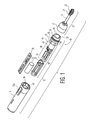
- Fig. 1 shows a small appliance, in particular a power toothbrush, in an exploded view generally at 10.
- appliance 10 includes a handle portion 12, which includes an internal drive assembly 14 with an interface registration element 16 at one end thereof, and a housing 18 for the handle portion.
- the interface element 16 is connected in a fixed physical relationship to an upper end of housing 18, as described in more detail below.
- the appliance also includes a head assembly 20, which, in the embodiment shown, includes a work piece assembly 21, which in turn includes a driven member 22.
- the driven member is joined to a brushhead arm 25 which has a brushhead 23 located at a distal end 24 thereof.
- the head assembly 20 is fixed to the interface element 16 in a manner described below.
- a nut 26 secures the head assembly 20 to interface element 16 by means of a threaded relationship.
- Other attachment means such as clamping or individual attachment elements could, however, be used.
- the internal drive assembly 14 includes a carrier element 32 to which holds a battery 34 and a PCB board 36 which carries the electronic drive circuitry for the toothbrush.
- a drive member 40 which for example, is an E-core electromagnet which includes an E-core stack 42, with a central coil winding 44.
- the E-core stack extends from an electromagnet frame 43, which is attached to and extends from carrier 32. Winding 44 is wound on a bobbin element 45 of the drive member 40.
- the distal end of the bobbin 45 is fixedly connected to or an integral part of a proximal end surface 46 of interface element 16, while the proximal end of bobbin 45 is fixedly connected to or an integral part of frame 43.
- the free ends of E-core stack 42 are also secured to the proximal end surface 46 of interface element 16.
- a plurality of registration elements 48 are a plurality of registration elements 48, such as narrow raised portions, which fit into corresponding slots 49 in the interior surface of housing 18 near the top end thereof.
- the open top housing 18 is installed over the completed internal drive assembly including the carrier 32 and is secured to the interface element 16 with the registration elements 48 fitting into the corresponding slots 49 in the interior housing surface.
- An upper portion of interface element 16 is hollow and defines a cup-like interior 49.
- a threaded portion 50 On the exterior upper periphery of interface element 16 is a threaded portion 50, which is configured to receive a mating threaded portion 56 on the internal surface of nut 26.
- the workpiece assembly 21 includes, in the embodiment shown, a movable brushhead arm 25 with a brushhead 23 on the distal end 24 thereof. The brushhead arm is moved by a driven member 22.
- driven member 22 On the proximal end of driven member 22 are permanent magnets 60, which interact cooperatively with the electromagnetic drive member in the handle to produce a back and forth motion of the rear end of the driven member 22. In the embodiment shown, this is a side-to-side motion with a slight arc.
- the resulting motion of brushhead 23 will vary, depending upon the rest of the workpiece assembly, which could include a motion conversion element changing the drive motion from arcuate side-to-side to rotary, as is the case for the apparatus of Fig. 1A . However, this is not necessary to the present invention.
- the workpiece assembly also includes a mounting member 61, which includes registration elements 62-62 which fit into corresponding slots 63 in the interior surface of the upper portion (the cup-like interior 49) of interface element 16, so that the driven member 22, with the permanent magnets 60, has a fixed registration relationship relative to interface element 16 and hence also to the drive member 40.
- Nut 26 is threaded on to the exterior upper portion of the interface element 16 to produce a completed appliance.
- Interface element 16 thus accomplishes a reliable and repeatable fixed physical relationship between the drive member 40, i.e. the electromagnet, and the driven element 22 which has permanent magnets 60 mounted at the rear end thereof, and which is joined to brushhead arm 21.
- the housing 18 acts mainly as a cover and is hence not critical to the operation of the drive arrangement of the appliance. However, the alignment of the housing in the interface element is important in certain applications, such as the positioning of the switch contacts in the carrier and the over-molded on/off button 18a on the housing as well as the alignment of any LED's on the PCB board with a window on the housing for battery level readings, etc.
- the present invention accomplishes this objective in an easy, repeatable, reliable manner through the use of the interface element and a top loading drive assembly connected thereto.
- an electromagnet is used as a drive member for an appliance such as a toothbrush.
- the electromagnet includes, as discussed above, winding 44, which is wound on bobbin 45.
- the bobbin with the winding is positioned over the center stack of the electromagnetic E-core.
- Other winding and bobbin arrangements are certainly possible and the one shown is for illustration only.
- the bobbin of the present invention is "split", in that it comprises two separate portions 70 and 72, which are then joined together.
- One portion 70 extends into and is part of a frame or base part 74 of the drive element.
- the base part 74 includes three pin connections 76-76, which form the terminal connections for the winding and the wire connections from the battery.
- the base part 74 must thus be able to withstand high temperatures.
- Portion 70 of the split bobbin is made from the same material as the base part. This material must also be able to withstand the pressure of the wire tension during winding of the coil therein, which is typically several pounds.
- the material for bobbin portion 70 and base part 74 must be strong enough that it will not crush even when it is relatively thin.
- the other portion 72 of the split bobbin extends into or is part of the rear surface of interface element 16. It is made from the same material as the interface element.
- the interface element 16 itself is made from a material, which is chemically resistant to the environmental conditions of the appliance, such as toothpaste and/or other chemical compounds for dental treatment, which may be encountered during operation of the appliance. Further, the material must have the capability of presenting a good cosmetic finish for aesthetic purposes, including the ability to be colored to match the other exposed portions of the toothbrush.
- the first portion 70 of the split bobbin which extends from or is an integral part of the frame or base part 74 of the drive element, includes a first section 75 which extends from base part 74 and a second section 77 which extends from the end of the first section 75.
- the first section 75 is slightly larger in exterior size than the second portion 77. In the embodiment shown, the first section 75 is approximately 3/8 inches long, while the second section is approximately 1/2 inch long.
- the second section 77 has slightly smaller dimensions (approximately 1/32-inch around its periphery relative to the first section 75. Extending outwardly (approximately 1/32 inch) from the top and bottom surfaces 80, 81 are ears 84-84, which have a slight each, outward bulge at a forward end thereof.
- Both portions 70 and 72 are rectangular in configuration and hollow.
- Bobbin portion 72 is approximately 5/8 inches long and has internal dimensions to receive the second section 77 of the first bobbin portion 70.
- Bobbin portion 72 also comprises two sections along its length. A first section is adjacent the interface element 16, while the other section extends from the first section to the end of portion 72. The external dimensions of the two sections are the same, but their internal diameters are different. The internal opening of the second, outboard section is smaller, resulting in a stronger section than the first section.
- slots 88 Extending inwardly from the outer edge 85 of the second bobbin portion 72 in the upper and lower opposed surfaces thereof, respectively, are slots 88 (one in each surface) which are configured to receive ears 84-84 of the first bobbin portion.
- the ears 84-84 with the slight outward bulge thereof, can be snapped into slots 88-88.
- the ears 84-84 are slightly different in configuration; the two slots 88-88 are also slightly different, arranged to mate with their associated ears 84-84.
- the two parts can be joined in only one particular orientation.
- Each ear uniquely fits its associated slot and not the other.
- the edge of the larger section 75 of portion 70 acts as a stop for the edge 85 of portion 72. This arrangement produces uniform length of the resulting bobbin assembly.
- the two bobbin portions are held together securely by the ear/slot combinations, although they can be pulled apart with the use of sufficient force.
- the coil wire is wound around the two joined portions of the bobbin, extending from the base part of the drive element to the rear surface 46 of the interface element, holding the two bobbin portions 70 and 72 firmly together.
- the firm joinder of the bobbin portions is accomplished as follows: First, the ears 84-84 are positioned in the slots 88-88. The two portions thus resist being pulled apart. Further, the second, outboard section of bobbin portion 72, overlaps outboard section 77 of portion 70 when the two portions are snapped together. The coil is then wound around the two portions. The tension of the coil winding is sufficient to compress the second outboard section of portion 72 into firm contact with section 77 of portion 70.
- Sections 77 and 75 of portion 70 are not deformed in any significant way since portion 70 is formed from a strong material.
- the outboard section of portion 72 is also not significantly deformed, since it has a small interior opening and overlaps section 77 of portion 70.
- the split bobbin arrangement described and shown herein permits the use of a material at the interface end of the bobbin which meets all of the requirements of that portion of the bobbin, i.e. chemically resistant and aesthetically pleasing, and a second material at the other end of the bobbin which meets all of the requirements of that end of the bobbin, i.e. heat-resistant to permit soldering and high strength to withstand the coil winding process.
- a registration assembly has been described which provides the required alignment capability between a driving member and a driven element. This is particularly advantageous for confined space devices.
- all of the critical parts of the appliance are attached directly to the interface element.
- the interface element, the split bobbin coil and E-core laminated stack comprise the drive system.
- the carrier and the control circuit are also attached to the interface element.
- the brushhead assembly is directly attached to the upper (cup) side of the interface element by means of the nut element.
- a split bobbin arrangement For devices using an electromagnetic driver with a coil winding, a split bobbin arrangement has been described which meets the stringent and heretofore irreconcilable requirements of a bobbin structure which needs to be strong and heat-resistant, but also chemical resistant, capable of being exposed to the environment and aesthetically pleasing.
Landscapes
- Health & Medical Sciences (AREA)
- Dentistry (AREA)
- Epidemiology (AREA)
- Life Sciences & Earth Sciences (AREA)
- Animal Behavior & Ethology (AREA)
- General Health & Medical Sciences (AREA)
- Public Health (AREA)
- Veterinary Medicine (AREA)
- Oral & Maxillofacial Surgery (AREA)
- Brushes (AREA)
Applications Claiming Priority (2)
| Application Number | Priority Date | Filing Date | Title |
|---|---|---|---|
| US10/139,293 US7122921B2 (en) | 2002-05-02 | 2002-05-02 | Top loading internal assembly for a power toothbrush |
| EP03715223.8A EP1503692B1 (fr) | 2002-05-02 | 2003-04-22 | Ensemble interne a chargement par le haut pour une brosse a dents electrique |
Related Parent Applications (3)
| Application Number | Title | Priority Date | Filing Date |
|---|---|---|---|
| EP03715223.8 Division | 2003-04-22 | ||
| EP03715223.8A Division EP1503692B1 (fr) | 2002-05-02 | 2003-04-22 | Ensemble interne a chargement par le haut pour une brosse a dents electrique |
| EP03715223.8A Division-Into EP1503692B1 (fr) | 2002-05-02 | 2003-04-22 | Ensemble interne a chargement par le haut pour une brosse a dents electrique |
Publications (2)
| Publication Number | Publication Date |
|---|---|
| EP2305169A1 true EP2305169A1 (fr) | 2011-04-06 |
| EP2305169B1 EP2305169B1 (fr) | 2018-01-03 |
Family
ID=29269535
Family Applications (2)
| Application Number | Title | Priority Date | Filing Date |
|---|---|---|---|
| EP03715223.8A Expired - Lifetime EP1503692B1 (fr) | 2002-05-02 | 2003-04-22 | Ensemble interne a chargement par le haut pour une brosse a dents electrique |
| EP10176347.2A Expired - Lifetime EP2305169B1 (fr) | 2002-05-02 | 2003-04-22 | Ensemble bobine pour une brosse à dents électrique |
Family Applications Before (1)
| Application Number | Title | Priority Date | Filing Date |
|---|---|---|---|
| EP03715223.8A Expired - Lifetime EP1503692B1 (fr) | 2002-05-02 | 2003-04-22 | Ensemble interne a chargement par le haut pour une brosse a dents electrique |
Country Status (9)
| Country | Link |
|---|---|
| US (2) | US7122921B2 (fr) |
| EP (2) | EP1503692B1 (fr) |
| JP (2) | JP4405911B2 (fr) |
| KR (2) | KR100978009B1 (fr) |
| CN (2) | CN100450458C (fr) |
| AU (1) | AU2003219412A1 (fr) |
| CA (2) | CA2483902C (fr) |
| DE (1) | DE20321197U1 (fr) |
| WO (1) | WO2003092534A2 (fr) |
Families Citing this family (36)
| Publication number | Priority date | Publication date | Assignee | Title |
|---|---|---|---|---|
| US6920659B2 (en) | 2001-01-12 | 2005-07-26 | Water Pik, Inc. | Toothbrush |
| US6955539B2 (en) | 2001-07-12 | 2005-10-18 | Water Pik, Inc. | Characterization of motion of dual motor oral hygiene device |
| JP4218413B2 (ja) * | 2003-05-16 | 2009-02-04 | パナソニック電工株式会社 | 振動、ローリング駆動両用リニアアクチュエータ及びそれを用いた電動歯ブラシ |
| US6856113B1 (en) | 2004-05-12 | 2005-02-15 | Cube Investments Limited | Central vacuum cleaning system motor control circuit mounting post, mounting configuration, and mounting methods |
| CA2580282C (fr) | 2004-09-17 | 2014-04-15 | Cube Investments Limited | Poignee d'un dispositif de nettoyage et sections boitier de poignee de dispositif de nettoyage |
| US20060234185A1 (en) * | 2005-02-17 | 2006-10-19 | Discus Dental Impressions Inc. | Ultrasonic dental tool having a light source |
| DE102005040136A1 (de) * | 2005-08-25 | 2007-03-01 | Braun Gmbh | Handteil einer elektrischen Zahnbürste sowie Ladeteil hierfür |
| US8732895B2 (en) | 2005-10-07 | 2014-05-27 | Cube Investments Limited | Central vacuum cleaner multiple vacuum source control |
| US7690075B2 (en) | 2005-10-07 | 2010-04-06 | Cube Investments Limited | Central vacuum cleaner control, unit and system with contaminant sensor |
| US7900315B2 (en) | 2005-10-07 | 2011-03-08 | Cube Investments Limited | Integrated central vacuum cleaner suction device and control |
| CA2562804C (fr) | 2005-10-07 | 2014-12-09 | Cube Investments Limited | Commandes croisees d'aspirateur central |
| US7765641B2 (en) * | 2005-12-30 | 2010-08-03 | Cube Investments Limited | Central vacuum cleaning system battery housing and handle |
| US8336155B2 (en) | 2009-04-21 | 2012-12-25 | Ranir, Llc | Replacement head for electric toothbrush |
| US20110041270A1 (en) * | 2009-08-24 | 2011-02-24 | Hsuan-Ju Chen | Toothbrush with education function |
| WO2011126326A2 (fr) * | 2010-04-08 | 2011-10-13 | 주식회사 엘지생활건강 | Brosse à dents électrique dotée d'une excellente efficacité de vibration |
| JP2013523312A (ja) * | 2010-04-08 | 2013-06-17 | エルジー ハウスホールド アンド ヘルス ケア カンパニー,リミテッド | 振動効率に優れた電動歯ブラシ |
| CN102126197B (zh) * | 2011-03-11 | 2012-07-04 | 许晓华 | 一种鱼眼接头定位模具 |
| CN106037977B (zh) | 2011-05-02 | 2018-06-29 | 沃特皮克公司 | 设计声波牙刷的方法 |
| JP5796408B2 (ja) * | 2011-08-24 | 2015-10-21 | オムロンヘルスケア株式会社 | 口腔ケア装置 |
| JP5995083B2 (ja) * | 2012-12-27 | 2016-09-21 | パナソニックIpマネジメント株式会社 | 電動リニアアクチュエーターおよびこの電動リニアアクチュエーターを有する出力軸振動型電動装置 |
| CA2905566C (fr) | 2013-03-15 | 2017-11-07 | Water Pik, Inc. | Brosse a dents sonique entrainee mecaniquement et nettoyeur inter-dentaire a eau |
| US9468511B2 (en) | 2013-03-15 | 2016-10-18 | Water Pik, Inc. | Electronic toothbrush with vibration dampening |
| CN103490581B (zh) * | 2013-09-23 | 2016-01-20 | 都佳宜电器制品(深圳)有限公司 | 摆动马达组合驱动装置及其方法 |
| US10952833B2 (en) | 2013-12-04 | 2021-03-23 | Ranir, Llc | Spring mechanism for power device |
| US9999486B2 (en) | 2015-03-18 | 2018-06-19 | Ranir, Llc | Spring mechanism for power device |
| US9929621B2 (en) | 2015-03-18 | 2018-03-27 | Ranir, Llc | Spring mechanism for power device |
| CN205568226U (zh) | 2015-07-08 | 2016-09-14 | 洁碧有限公司 | 刷牙装置 |
| JP6458720B2 (ja) * | 2015-12-04 | 2019-01-30 | トヨタ自動車株式会社 | リアクトル |
| CN107240973B (zh) * | 2016-03-28 | 2020-01-14 | 微网有限公司 | 直接冷却式的机头 |
| US10561480B2 (en) | 2016-05-09 | 2020-02-18 | Water Pik, Inc. | Load sensing for oral devices |
| CN106175957B (zh) * | 2016-06-30 | 2018-01-02 | 上海携福电器有限公司 | 用于电动清洁用具驱动装置的固定结构 |
| EP3554418B1 (fr) | 2016-12-15 | 2021-06-30 | Water Pik, Inc. | Dispositif de brossage à éléments d'éclairage |
| USD844997S1 (en) | 2016-12-15 | 2019-04-09 | Water Pik, Inc. | Toothbrush handle |
| USD845636S1 (en) | 2016-12-15 | 2019-04-16 | Water Pik, Inc. | Toothbrush handle |
| CN109966000A (zh) * | 2019-04-29 | 2019-07-05 | 深圳市卓一品科技有限公司 | 低速平转式电动牙刷 |
| CN110200719B (zh) * | 2019-07-09 | 2021-04-20 | 苏州迈瑞特电子科技有限公司 | 一种防水型锂电池无水电动超声波洁牙机 |
Citations (8)
| Publication number | Priority date | Publication date | Assignee | Title |
|---|---|---|---|---|
| FR870822A (fr) * | 1941-03-14 | 1942-03-25 | Instrument d'hygiène, à organe oscillant plus particulièrement destiné à l'hygiène buccale | |
| US3375583A (en) * | 1966-03-10 | 1968-04-02 | C & B Inc | Ultrasonic dental tool |
| US3654502A (en) * | 1970-06-24 | 1972-04-04 | Countronic Corp | Ultrasonic tool |
| EP0138014A1 (fr) * | 1983-10-01 | 1985-04-24 | GRUNDIG E.M.V. Elektro-Mechanische Versuchsanstalt Max Grundig holländ. Stiftung & Co. KG. | Corps de bobine de chambre |
| EP0325467A1 (fr) * | 1988-01-19 | 1989-07-26 | John Fluke Mfg. Co., Inc. | Transformateur modulaire de puissance à haute fréquence |
| US5263218A (en) * | 1991-03-21 | 1993-11-23 | Gemtech | Vibrating toothbrush using a magnetic driver |
| EP0642769A1 (fr) * | 1993-09-14 | 1995-03-15 | Dentsply International | Pièce à main dentaire et/ou médicale avec bobine électrique |
| US20010024152A1 (en) * | 2000-03-24 | 2001-09-27 | Sinobu Miyazaki | Electromagnetic induction device |
Family Cites Families (31)
| Publication number | Priority date | Publication date | Assignee | Title |
|---|---|---|---|---|
| US2650993A (en) * | 1949-01-31 | 1953-09-01 | Oster John Mfg Co | Electric hair clipper |
| GB1031350A (en) | 1963-12-12 | 1966-06-02 | Ericsson Telephones Ltd | Improved coil former |
| US3300664A (en) * | 1964-04-02 | 1967-01-24 | Gen Electric | Toothbrush power handle assembly |
| US3840795A (en) * | 1964-07-07 | 1974-10-08 | Sunbeam Corp | Hand held battery operated device and charging means therefor |
| US3418552A (en) * | 1965-06-08 | 1968-12-24 | Gen Electric | Separable transformer battery charger |
| US3549990A (en) * | 1968-08-19 | 1970-12-22 | Jerome S Hochheiser | Non-sparking a-c connectors |
| US3577579A (en) * | 1969-10-29 | 1971-05-04 | John P Duve | Electric toothbrush |
| DE2248162C2 (de) * | 1972-09-30 | 1982-11-18 | Licentia Patent-Verwaltungs-Gmbh, 6000 Frankfurt | Zahnbürste |
| US4374354A (en) * | 1981-06-23 | 1983-02-15 | Teledyne Industries, Inc. | Rechargeable electric portable appliance |
| JPS5822555A (ja) * | 1981-07-29 | 1983-02-09 | Matsushita Electric Works Ltd | 電気機械器具 |
| JPS63130007A (ja) * | 1986-11-21 | 1988-06-02 | 松下電工株式会社 | 電動歯ブラシの駆動部組立構造 |
| JP2781176B2 (ja) * | 1988-02-17 | 1998-07-30 | 株式会社ユニシアジェックス | アクチュエータ |
| DE4020305A1 (de) | 1990-06-26 | 1992-01-09 | Siemens Ag | Spule zur oberflaechenmontage |
| US5189751A (en) * | 1991-03-21 | 1993-03-02 | Gemtech, Inc. | Vibrating toothbrush using a magnetic driver |
| JP2565620Y2 (ja) * | 1992-06-25 | 1998-03-18 | 三洋電機株式会社 | 電動歯ブラシ |
| US5565833A (en) * | 1993-05-28 | 1996-10-15 | Circuit Breaker Industries Limited | Method of fitting a coil onto a bobbin |
| US5435034A (en) * | 1993-07-28 | 1995-07-25 | Bausch & Lomb Incorporated | Electric toothbrush |
| WO1995033419A1 (fr) * | 1994-06-06 | 1995-12-14 | Teledyne Water Pik Division Of Teledyne Industries, Inc. | Brosse a dents electrique a hautes frequences |
| US5784742A (en) * | 1995-06-23 | 1998-07-28 | Optiva Corporation | Toothbrush with adaptive load sensor |
| US5706542A (en) * | 1995-06-27 | 1998-01-13 | Okada; Eiji | Electrically driven toothbrush |
| DE19602642B4 (de) * | 1996-01-25 | 2008-07-17 | Tyco Electronics Logistics Ag | Elektromagnetisches Relais und Verfahren zu dessen Herstellung |
| WO1997034710A1 (fr) * | 1996-03-21 | 1997-09-25 | Sunstar Inc. | Vibreur et appareil d'hygiene buccale utilisant un tel vibreur |
| JP3791055B2 (ja) * | 1996-07-11 | 2006-06-28 | サンスター株式会社 | 口腔内衛生装置 |
| US5815872A (en) * | 1997-08-08 | 1998-10-06 | Optiva Corporation | Pressure overload indicator system for power toothbrushes |
| GB2339336B (en) * | 1998-06-16 | 2000-08-16 | Huntleigh Technology Plc | Magnetic actuator |
| US6000083A (en) * | 1998-09-30 | 1999-12-14 | Dr. Johns Products, Ltd. | Electric toothbrush |
| US6371294B1 (en) * | 1998-09-30 | 2002-04-16 | The Procter & Gamble Company | Electric toothbrush |
| US6486760B2 (en) | 1998-12-07 | 2002-11-26 | Matsushita Electric Works, Ltd. | Electromagnetic relay |
| US6550745B2 (en) * | 1999-12-21 | 2003-04-22 | Gary E. Bergstrom | Flat lamination solenoid |
| US6836917B2 (en) * | 2001-05-07 | 2005-01-04 | The Procter & Gamble Company | Replaceable head electric toothbrush and connection structure therefor |
| US20050148895A1 (en) * | 2004-01-06 | 2005-07-07 | Misczynski Dale J. | Method and apparatus for ECG derived sleep monitoring of a user |
-
2002
- 2002-05-02 US US10/139,293 patent/US7122921B2/en not_active Expired - Lifetime
-
2003
- 2003-04-22 AU AU2003219412A patent/AU2003219412A1/en not_active Abandoned
- 2003-04-22 CA CA2483902A patent/CA2483902C/fr not_active Expired - Lifetime
- 2003-04-22 DE DE20321197U patent/DE20321197U1/de not_active Expired - Lifetime
- 2003-04-22 EP EP03715223.8A patent/EP1503692B1/fr not_active Expired - Lifetime
- 2003-04-22 CN CNB038097508A patent/CN100450458C/zh not_active Expired - Fee Related
- 2003-04-22 KR KR1020097022797A patent/KR100978009B1/ko not_active Expired - Fee Related
- 2003-04-22 WO PCT/IB2003/001590 patent/WO2003092534A2/fr not_active Ceased
- 2003-04-22 EP EP10176347.2A patent/EP2305169B1/fr not_active Expired - Lifetime
- 2003-04-22 KR KR1020047017370A patent/KR100956306B1/ko not_active Expired - Fee Related
- 2003-04-22 JP JP2004500722A patent/JP4405911B2/ja not_active Expired - Fee Related
- 2003-04-22 CN CN2007101995110A patent/CN101268969B/zh not_active Expired - Fee Related
- 2003-04-22 CA CA2700645A patent/CA2700645C/fr not_active Expired - Lifetime
-
2006
- 2006-08-08 US US11/501,373 patent/US7482906B2/en not_active Expired - Lifetime
-
2009
- 2009-09-03 JP JP2009203607A patent/JP5155268B2/ja not_active Expired - Fee Related
Patent Citations (8)
| Publication number | Priority date | Publication date | Assignee | Title |
|---|---|---|---|---|
| FR870822A (fr) * | 1941-03-14 | 1942-03-25 | Instrument d'hygiène, à organe oscillant plus particulièrement destiné à l'hygiène buccale | |
| US3375583A (en) * | 1966-03-10 | 1968-04-02 | C & B Inc | Ultrasonic dental tool |
| US3654502A (en) * | 1970-06-24 | 1972-04-04 | Countronic Corp | Ultrasonic tool |
| EP0138014A1 (fr) * | 1983-10-01 | 1985-04-24 | GRUNDIG E.M.V. Elektro-Mechanische Versuchsanstalt Max Grundig holländ. Stiftung & Co. KG. | Corps de bobine de chambre |
| EP0325467A1 (fr) * | 1988-01-19 | 1989-07-26 | John Fluke Mfg. Co., Inc. | Transformateur modulaire de puissance à haute fréquence |
| US5263218A (en) * | 1991-03-21 | 1993-11-23 | Gemtech | Vibrating toothbrush using a magnetic driver |
| EP0642769A1 (fr) * | 1993-09-14 | 1995-03-15 | Dentsply International | Pièce à main dentaire et/ou médicale avec bobine électrique |
| US20010024152A1 (en) * | 2000-03-24 | 2001-09-27 | Sinobu Miyazaki | Electromagnetic induction device |
Also Published As
| Publication number | Publication date |
|---|---|
| KR20040106412A (ko) | 2004-12-17 |
| US7482906B2 (en) | 2009-01-27 |
| EP1503692A2 (fr) | 2005-02-09 |
| CA2483902A1 (fr) | 2003-11-13 |
| CN101268969B (zh) | 2011-11-02 |
| KR100956306B1 (ko) | 2010-05-10 |
| CA2700645A1 (fr) | 2003-11-13 |
| EP2305169B1 (fr) | 2018-01-03 |
| CA2483902C (fr) | 2011-06-28 |
| JP2005524443A (ja) | 2005-08-18 |
| JP4405911B2 (ja) | 2010-01-27 |
| CA2700645C (fr) | 2012-07-03 |
| WO2003092534A3 (fr) | 2004-02-05 |
| CN101268969A (zh) | 2008-09-24 |
| US7122921B2 (en) | 2006-10-17 |
| JP5155268B2 (ja) | 2013-03-06 |
| EP1503692B1 (fr) | 2015-04-08 |
| US20030204925A1 (en) | 2003-11-06 |
| CN100450458C (zh) | 2009-01-14 |
| CN1649550A (zh) | 2005-08-03 |
| KR100978009B1 (ko) | 2010-08-25 |
| JP2009279463A (ja) | 2009-12-03 |
| WO2003092534A2 (fr) | 2003-11-13 |
| AU2003219412A1 (en) | 2003-11-17 |
| DE20321197U1 (de) | 2006-05-18 |
| KR20090127945A (ko) | 2009-12-14 |
| US20060267419A1 (en) | 2006-11-30 |
Similar Documents
| Publication | Publication Date | Title |
|---|---|---|
| EP2305169B1 (fr) | Ensemble bobine pour une brosse à dents électrique | |
| CN101150018B (zh) | 触发开关 | |
| JP2004120873A (ja) | レゾルバの入出力端子構造及びそれを用いたレゾルバの結線方法 | |
| CA2015139A1 (fr) | Support a brosse pour moteur electrique | |
| CA2062647C (fr) | Structure de couplage d'enroulements inducteurs aux balais d'un moteur | |
| US9030059B2 (en) | Actuator | |
| EP0682400B1 (fr) | Commutateur supprimant du bruit | |
| US20070103265A1 (en) | Electromagnetic switch of starter | |
| EP1351369A2 (fr) | Structure de connection d'un résolveur | |
| US20050134140A1 (en) | Motor mounting base | |
| CN217154121U (zh) | 一种免除连接器的灯具安装结构 | |
| JPH0646202Y2 (ja) | 小型モータの端子構造 | |
| JP2698726B2 (ja) | 電磁弁の製造方法 | |
| WO1992004759A1 (fr) | Borne externe de moteur | |
| JP2528733B2 (ja) | 小型モ―タ | |
| JPH1189210A (ja) | リニアモータ | |
| JPS5927266Y2 (ja) | 電源切換機構を有する電磁駆動装置 | |
| KR20040071518A (ko) | 전자클러치의 필드코일 어셈블리 | |
| JPH09276239A (ja) | 生体接触電極装置 | |
| JPH0723914Y2 (ja) | 電気接続具 | |
| JPH0737727A (ja) | スイッチ用電流トランス | |
| JPH08280150A (ja) | 小型モータ | |
| KR20000009126U (ko) | 진공청소기의 슬라이드 볼륨 기판 고정장치 |
Legal Events
| Date | Code | Title | Description |
|---|---|---|---|
| PUAI | Public reference made under article 153(3) epc to a published international application that has entered the european phase |
Free format text: ORIGINAL CODE: 0009012 |
|
| AC | Divisional application: reference to earlier application |
Ref document number: 1503692 Country of ref document: EP Kind code of ref document: P |
|
| AK | Designated contracting states |
Kind code of ref document: A1 Designated state(s): AT BE BG CH CY CZ DE DK EE ES FI FR GB GR HU IE IT LI LU MC NL PT RO SE SI SK TR |
|
| 17P | Request for examination filed |
Effective date: 20111006 |
|
| RAP1 | Party data changed (applicant data changed or rights of an application transferred) |
Owner name: KONINKLIJKE PHILIPS N.V. |
|
| 17Q | First examination report despatched |
Effective date: 20160311 |
|
| GRAP | Despatch of communication of intention to grant a patent |
Free format text: ORIGINAL CODE: EPIDOSNIGR1 |
|
| INTG | Intention to grant announced |
Effective date: 20170728 |
|
| RIN1 | Information on inventor provided before grant (corrected) |
Inventor name: HALL, SCOTT, E. Inventor name: HANELA, CRAIG, D. Inventor name: TAYLOR, RICHARD, K. |
|
| GRAS | Grant fee paid |
Free format text: ORIGINAL CODE: EPIDOSNIGR3 |
|
| GRAA | (expected) grant |
Free format text: ORIGINAL CODE: 0009210 |
|
| AC | Divisional application: reference to earlier application |
Ref document number: 1503692 Country of ref document: EP Kind code of ref document: P |
|
| AK | Designated contracting states |
Kind code of ref document: B1 Designated state(s): AT BE BG CH CY CZ DE DK EE ES FI FR GB GR HU IE IT LI LU MC NL PT RO SE SI SK TR |
|
| REG | Reference to a national code |
Ref country code: GB Ref legal event code: FG4D |
|
| REG | Reference to a national code |
Ref country code: CH Ref legal event code: EP Ref country code: AT Ref legal event code: REF Ref document number: 959557 Country of ref document: AT Kind code of ref document: T Effective date: 20180115 |
|
| REG | Reference to a national code |
Ref country code: IE Ref legal event code: FG4D |
|
| REG | Reference to a national code |
Ref country code: DE Ref legal event code: R096 Ref document number: 60350897 Country of ref document: DE |
|
| REG | Reference to a national code |
Ref country code: FR Ref legal event code: PLFP Year of fee payment: 16 |
|
| REG | Reference to a national code |
Ref country code: NL Ref legal event code: MP Effective date: 20180103 |
|
| REG | Reference to a national code |
Ref country code: AT Ref legal event code: MK05 Ref document number: 959557 Country of ref document: AT Kind code of ref document: T Effective date: 20180103 |
|
| PG25 | Lapsed in a contracting state [announced via postgrant information from national office to epo] |
Ref country code: NL Free format text: LAPSE BECAUSE OF FAILURE TO SUBMIT A TRANSLATION OF THE DESCRIPTION OR TO PAY THE FEE WITHIN THE PRESCRIBED TIME-LIMIT Effective date: 20180103 |
|
| PG25 | Lapsed in a contracting state [announced via postgrant information from national office to epo] |
Ref country code: ES Free format text: LAPSE BECAUSE OF FAILURE TO SUBMIT A TRANSLATION OF THE DESCRIPTION OR TO PAY THE FEE WITHIN THE PRESCRIBED TIME-LIMIT Effective date: 20180103 Ref country code: FI Free format text: LAPSE BECAUSE OF FAILURE TO SUBMIT A TRANSLATION OF THE DESCRIPTION OR TO PAY THE FEE WITHIN THE PRESCRIBED TIME-LIMIT Effective date: 20180103 Ref country code: CY Free format text: LAPSE BECAUSE OF FAILURE TO SUBMIT A TRANSLATION OF THE DESCRIPTION OR TO PAY THE FEE WITHIN THE PRESCRIBED TIME-LIMIT Effective date: 20180103 |
|
| PG25 | Lapsed in a contracting state [announced via postgrant information from national office to epo] |
Ref country code: AT Free format text: LAPSE BECAUSE OF FAILURE TO SUBMIT A TRANSLATION OF THE DESCRIPTION OR TO PAY THE FEE WITHIN THE PRESCRIBED TIME-LIMIT Effective date: 20180103 Ref country code: SE Free format text: LAPSE BECAUSE OF FAILURE TO SUBMIT A TRANSLATION OF THE DESCRIPTION OR TO PAY THE FEE WITHIN THE PRESCRIBED TIME-LIMIT Effective date: 20180103 Ref country code: GR Free format text: LAPSE BECAUSE OF FAILURE TO SUBMIT A TRANSLATION OF THE DESCRIPTION OR TO PAY THE FEE WITHIN THE PRESCRIBED TIME-LIMIT Effective date: 20180404 Ref country code: BG Free format text: LAPSE BECAUSE OF FAILURE TO SUBMIT A TRANSLATION OF THE DESCRIPTION OR TO PAY THE FEE WITHIN THE PRESCRIBED TIME-LIMIT Effective date: 20180403 |
|
| REG | Reference to a national code |
Ref country code: DE Ref legal event code: R097 Ref document number: 60350897 Country of ref document: DE |
|
| PG25 | Lapsed in a contracting state [announced via postgrant information from national office to epo] |
Ref country code: RO Free format text: LAPSE BECAUSE OF FAILURE TO SUBMIT A TRANSLATION OF THE DESCRIPTION OR TO PAY THE FEE WITHIN THE PRESCRIBED TIME-LIMIT Effective date: 20180103 Ref country code: IT Free format text: LAPSE BECAUSE OF FAILURE TO SUBMIT A TRANSLATION OF THE DESCRIPTION OR TO PAY THE FEE WITHIN THE PRESCRIBED TIME-LIMIT Effective date: 20180103 Ref country code: EE Free format text: LAPSE BECAUSE OF FAILURE TO SUBMIT A TRANSLATION OF THE DESCRIPTION OR TO PAY THE FEE WITHIN THE PRESCRIBED TIME-LIMIT Effective date: 20180103 |
|
| PLBE | No opposition filed within time limit |
Free format text: ORIGINAL CODE: 0009261 |
|
| STAA | Information on the status of an ep patent application or granted ep patent |
Free format text: STATUS: NO OPPOSITION FILED WITHIN TIME LIMIT |
|
| PG25 | Lapsed in a contracting state [announced via postgrant information from national office to epo] |
Ref country code: SK Free format text: LAPSE BECAUSE OF FAILURE TO SUBMIT A TRANSLATION OF THE DESCRIPTION OR TO PAY THE FEE WITHIN THE PRESCRIBED TIME-LIMIT Effective date: 20180103 Ref country code: MC Free format text: LAPSE BECAUSE OF FAILURE TO SUBMIT A TRANSLATION OF THE DESCRIPTION OR TO PAY THE FEE WITHIN THE PRESCRIBED TIME-LIMIT Effective date: 20180103 Ref country code: CZ Free format text: LAPSE BECAUSE OF FAILURE TO SUBMIT A TRANSLATION OF THE DESCRIPTION OR TO PAY THE FEE WITHIN THE PRESCRIBED TIME-LIMIT Effective date: 20180103 Ref country code: DK Free format text: LAPSE BECAUSE OF FAILURE TO SUBMIT A TRANSLATION OF THE DESCRIPTION OR TO PAY THE FEE WITHIN THE PRESCRIBED TIME-LIMIT Effective date: 20180103 |
|
| REG | Reference to a national code |
Ref country code: CH Ref legal event code: PL |
|
| 26N | No opposition filed |
Effective date: 20181005 |
|
| REG | Reference to a national code |
Ref country code: BE Ref legal event code: MM Effective date: 20180430 |
|
| REG | Reference to a national code |
Ref country code: IE Ref legal event code: MM4A |
|
| PG25 | Lapsed in a contracting state [announced via postgrant information from national office to epo] |
Ref country code: LU Free format text: LAPSE BECAUSE OF NON-PAYMENT OF DUE FEES Effective date: 20180422 |
|
| PG25 | Lapsed in a contracting state [announced via postgrant information from national office to epo] |
Ref country code: LI Free format text: LAPSE BECAUSE OF NON-PAYMENT OF DUE FEES Effective date: 20180430 Ref country code: SI Free format text: LAPSE BECAUSE OF FAILURE TO SUBMIT A TRANSLATION OF THE DESCRIPTION OR TO PAY THE FEE WITHIN THE PRESCRIBED TIME-LIMIT Effective date: 20180103 Ref country code: BE Free format text: LAPSE BECAUSE OF NON-PAYMENT OF DUE FEES Effective date: 20180430 Ref country code: CH Free format text: LAPSE BECAUSE OF NON-PAYMENT OF DUE FEES Effective date: 20180430 |
|
| PG25 | Lapsed in a contracting state [announced via postgrant information from national office to epo] |
Ref country code: IE Free format text: LAPSE BECAUSE OF NON-PAYMENT OF DUE FEES Effective date: 20180422 |
|
| PG25 | Lapsed in a contracting state [announced via postgrant information from national office to epo] |
Ref country code: HU Free format text: LAPSE BECAUSE OF FAILURE TO SUBMIT A TRANSLATION OF THE DESCRIPTION OR TO PAY THE FEE WITHIN THE PRESCRIBED TIME-LIMIT; INVALID AB INITIO Effective date: 20030422 Ref country code: PT Free format text: LAPSE BECAUSE OF FAILURE TO SUBMIT A TRANSLATION OF THE DESCRIPTION OR TO PAY THE FEE WITHIN THE PRESCRIBED TIME-LIMIT Effective date: 20180103 |
|
| PGFP | Annual fee paid to national office [announced via postgrant information from national office to epo] |
Ref country code: DE Payment date: 20210428 Year of fee payment: 19 Ref country code: FR Payment date: 20210427 Year of fee payment: 19 |
|
| PGFP | Annual fee paid to national office [announced via postgrant information from national office to epo] |
Ref country code: TR Payment date: 20210413 Year of fee payment: 19 Ref country code: GB Payment date: 20210426 Year of fee payment: 19 |
|
| REG | Reference to a national code |
Ref country code: DE Ref legal event code: R119 Ref document number: 60350897 Country of ref document: DE |
|
| GBPC | Gb: european patent ceased through non-payment of renewal fee |
Effective date: 20220422 |
|
| PG25 | Lapsed in a contracting state [announced via postgrant information from national office to epo] |
Ref country code: GB Free format text: LAPSE BECAUSE OF NON-PAYMENT OF DUE FEES Effective date: 20220422 Ref country code: FR Free format text: LAPSE BECAUSE OF NON-PAYMENT OF DUE FEES Effective date: 20220430 Ref country code: DE Free format text: LAPSE BECAUSE OF NON-PAYMENT OF DUE FEES Effective date: 20221103 |