EP2305555A1 - Appareil de rétablissement du moment de redressement pour navire, et navire de transport d automobiles équipé de ce dernier - Google Patents
Appareil de rétablissement du moment de redressement pour navire, et navire de transport d automobiles équipé de ce dernier Download PDFInfo
- Publication number
- EP2305555A1 EP2305555A1 EP08826096A EP08826096A EP2305555A1 EP 2305555 A1 EP2305555 A1 EP 2305555A1 EP 08826096 A EP08826096 A EP 08826096A EP 08826096 A EP08826096 A EP 08826096A EP 2305555 A1 EP2305555 A1 EP 2305555A1
- Authority
- EP
- European Patent Office
- Prior art keywords
- watertight
- ship
- flooding
- seawater inlet
- seawater
- Prior art date
- Legal status (The legal status is an assumption and is not a legal conclusion. Google has not performed a legal analysis and makes no representation as to the accuracy of the status listed.)
- Granted
Links
Images



Classifications
-
- B—PERFORMING OPERATIONS; TRANSPORTING
- B63—SHIPS OR OTHER WATERBORNE VESSELS; RELATED EQUIPMENT
- B63B—SHIPS OR OTHER WATERBORNE VESSELS; EQUIPMENT FOR SHIPPING
- B63B43/00—Improving safety of vessels, e.g. damage control, not otherwise provided for
- B63B43/02—Improving safety of vessels, e.g. damage control, not otherwise provided for reducing risk of capsizing or sinking
- B63B43/04—Improving safety of vessels, e.g. damage control, not otherwise provided for reducing risk of capsizing or sinking by improving stability
- B63B43/045—Improving safety of vessels, e.g. damage control, not otherwise provided for reducing risk of capsizing or sinking by improving stability by decreasing the free surface effect of water entered in enclosed decks
-
- B—PERFORMING OPERATIONS; TRANSPORTING
- B63—SHIPS OR OTHER WATERBORNE VESSELS; RELATED EQUIPMENT
- B63B—SHIPS OR OTHER WATERBORNE VESSELS; EQUIPMENT FOR SHIPPING
- B63B35/00—Vessels or similar floating structures specially adapted for specific purposes and not otherwise provided for
- B63B35/54—Ferries
-
- B—PERFORMING OPERATIONS; TRANSPORTING
- B63—SHIPS OR OTHER WATERBORNE VESSELS; RELATED EQUIPMENT
- B63B—SHIPS OR OTHER WATERBORNE VESSELS; EQUIPMENT FOR SHIPPING
- B63B43/00—Improving safety of vessels, e.g. damage control, not otherwise provided for
- B63B43/24—Arrangements of watertight doors in bulkheads
Definitions
- the present invention relates to a ship stability recovery system for securing a ship's stability when the ship is damaged and a car carrier equipped with the same.
- a ship such as a passenger boat having a plurality of compartments and provided with a water trap in the hull
- the water trap being structured as a wall element for partitioning adjacent compartments, which is given for the purpose of limiting the amount of flooding water to secure the ship's stability when the ship is damaged
- the wall element includes a fire-resistant main wall element that supports a predetermined load, and a fire-resistant additional element that forms a wall partitioning adjacent compartments together with the main wall element and is located under the main wall element, with no liquid filled inside.
- the additional element blocks movement of a heated gas between the adjacent compartments, while it allows movement of seawater to the other compartment when the seawater enters one of the adjacent compartments.
- a required value of GoM transverse metacentric height
- GoM transverse metacentric height
- ballast for lowering the center of gravity would be necessary, which, for a car carrier or the like, will cause a problem that the number of vehicles that can be loaded is decreased.
- Patent Literature 2 Another type of ship has also been proposed (see, for example, Patent Literature 2), which includes a flat-bottomed main hull and a submerged tank auxiliary hull that is constituted by adding, under the bottom of the main hull, a submerged tank external hull having an opening for transmitting pressure of incoming and outgoing seawater and an air vent pipe.
- a joining and securing keel (fin keel) is provided between the lower part of the bottom of the main hull and the interior of the submerged tank auxiliary hull, so that the ship is formed (constituted) by the main hull, which serves as the ship based on conventional ship theories, and the submerged tank auxiliary hull that encompasses a new concept and bears the function of preventing a capsize of the ship.
- the apparent center of gravity is moved to a lower part of the ship so that it is not easily capsized.
- Patent Literature 2 is substantially identical to a ship provided with a ballast for lowering the center of gravity, and so it has the problem that the number of vehicles that can be loaded is decreased.
- the present invention was proposed to solve the above problems, its object being to provide a stability recovery system for a ship having a huge auxiliary buoyancy such as a void space (pipe space) or the like near the bottom of the ship, the system being designed to secure the ship's stability when the ship is damaged by effectively utilizing this void space (pipe space) or the like, and a car carrier equipped with this system.
- a stability recovery system for a ship having a huge auxiliary buoyancy such as a void space (pipe space) or the like near the bottom of the ship, the system being designed to secure the ship's stability when the ship is damaged by effectively utilizing this void space (pipe space) or the like, and a car carrier equipped with this system.
- the present invention was made to solve the above conventional problems.
- the invention set forth in respective claims resides in a ship stability recovery system and a car carrier equipped with the same, adopting various means as will be respectively described in the following:
- the seawater inlet means provided in the lowermost watertight deck is opened, so that the seawater that has entered the ship is introduced into the void space (pipe space) and thereby the void space (pipe space), which usually provides a huge auxiliary buoyancy, can be made to function as a sort of a seawater ballast tank, whereby the ship's stability can be recovered.
- FIG. 1 to FIG. 6 Various embodiments of the present invention will be hereinafter described with reference to FIG. 1 to FIG. 6 .
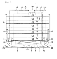
- FIG. 1 is a front cross-sectional view of a car carrier equipped with a ship stability recovery system according to a first embodiment of the present invention
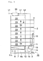
- FIG. 2 is a circuit diagram of a stability monitoring and control system of the same.
- FIG. 3 is a front cross-sectional view of a car carrier equipped with a ship stability recovery system according to a second embodiment of the present invention
- FIG. 4 is a front cross-sectional view of a car carrier equipped with a ship stability recovery system according to a third embodiment of the present invention
- FIG. 5 is a front cross-sectional view of a car carrier equipped with a ship stability recovery system according to a fourth embodiment of the present invention
- FIG. 6 is a front cross-sectional view of a car carrier equipped with a ship stability recovery system according to a fifth embodiment of the present invention.
- the car carrier 1 is formed to have a generally box-like cross-sectional shape with side shell plates 2 and a bottom shell plate 3.
- a freeboard deck 4 (deck for transferring vehicles to and from the ship, watertight deck), plural layers of watertight decks 5a and 5b for vehicle stowage and multiple layers of non-watertight decks 6 for vehicle stowage.
- the watertight freeboard deck 4 is provided near the center in the up and down direction of the car carrier 1.
- An outboard ramp (not shown) is coupled to this freeboard deck 4 for vehicle roll-on/roll-off.
- the watertight deck 5a for vehicle stowage is provided in a lowermost part of the car carrier 1, and the watertight deck 5b for vehicle stowage is also provided above the freeboard deck 4.
- At least one layer or more of non-watertight deck(s) 6 for vehicle stowage are provided.
- Plural layers (5 to 7 layers) of vehicle-stowage non-watertight decks 6 are provided above the upper watertight deck 5b, too.
- Multiple layers (e.g. 10 to 12 layers) of vehicle stowage compartments CS are formed between the freeboard deck 4, plural layers of watertight decks 5a and 5b, and multiple layers of non-watertight decks 6.
- ballast tank 7 (or fuel tank or the like) is provided below the lowermost vehicle-stowage watertight deck 5a.
- the tank In the case with a fuel tank, the tank is provided a certain distance above the bottom shell plate 3, as it needs to have a double shell design to prevent a fuel spill when the ship bottom is damaged.
- a void space 8 (pipe space) is formed between the bottom shell plate 3 and the lowermost watertight deck 5a or a tank bottom plate of the ballast tank 7 (or the fuel tank or the like), and a large number of pipes 9 are laid out in this void space 8 for pumping ballast water or fuel or the like.
- This void space 8 (or void space) is not used as a (fixed or seawater) ballast or the like, and provides a huge auxiliary buoyancy.
- the ship stability recovery system and the car carrier equipped with the same of this embodiment are designed to enable a ship which, while having the huge auxiliary buoyancy of the void space 8, cannot effectively utilize this auxiliary buoyancy, to recover its remaining stability.
- the invention takes into account that many conventional ships, while they satisfy required specifications in a full load condition, do not satisfy required specifications particularly in a ballast loaded condition because of a lack of remaining stability.
- the ship stability recovery system and the car carrier equipped with the same of this embodiment in view of the fact that required specifications can be met in a full load condition, the flooded volume is increased to deepen the draft after the flooding and to secure stability (GZ), by effectively using the huge auxiliary buoyancy to secure remaining stability.
- a watertight door 16 (including various forms such as a watertight hatch) is provided to a seawater inlet 13 opened in the lowermost vehicle-stowage watertight deck 5 respectively near the left and right side shell plates 2.
- the watertight door 16 is coupled at one end to a flange or the like of the seawater inlet 13 with a hinge pin or the like, the other end thereof being closed with a stopper 22 (including various forms such as a key) as shown in FIG. 2 .
- the watertight door opening system 24 should not be limited to the one constituted by the stopper 22 and the hydraulic cylinder unit 23, and it may be an open/close hydraulic cylinder that opens as well as closes the watertight door 16.
- the hydraulic cylinder unit 23 may include, not only a hydraulic cylinder, but also various types of valves that control the flow of operating oil and electromagnetic coils or the like for driving the valves.
- a seawater inlet means 25 remotely operable to open is constituted by the seawater inlet 13, flange, watertight door 16, stopper 22, and hydraulic cylinder unit 23 or the like.
- seawater inlet means 25 provided in the lowermost vehicle-stowage watertight deck 5a in this embodiment can be opened by remote control.
- the seawater inlet means 25 can be readily opened by remote control even if the place where the means is located is flooded with seawater.
- a flooding detection system 11 such as a flooding detector, TV camera or a level switch and the like is provided. It is desirable to provide a plurality of the flooding detection systems 11 along the fore-and-aft direction (e.g. at least at three locations including the vicinity of the bow, center, and the vicinity of the stern) respectively near the port and starboard side shell plates 2.
- the flooding detection system 11 may include, for example, an electric wire or optical fiber and the like attached to an inner surface of the side shell plates 2 so as to detect flooding by sensing that the electric wire or optical fiber has been cut off due to a hull breach.
- a water gauge 12 is provided in the void space 8 for detecting the water level of seawater that has flowed in.
- the ship of this embodiment is provided with the water gauge 12 in the void space 8, because its design presupposes introduction of seawater into the void space 8.
- This water gauge 12 may be constituted, for example, by level switches (float switches) provided at least at three locations including a lower part, an upper part, and a central part of the void space 8.
- level switches float switches
- a stability monitoring and control system 30 is provided in a non-watertight compartment above the ship's freeboard deck 4 of the car carrier 1, for example, in a wheel house or a cargo control room or the like.
- the stability monitoring and control system 30 and the watertight door opening system 24 for driving the watertight door 16 are connected via a valve control signal line L3.
- the stability monitoring and control system 30 and the flooding detection system 11 are connected via a detection signal line L1.
- the stability monitoring and control system 30 and the water gauge 12 are connected via a seawater level detection signal line L2.
- the stability monitoring and control system 30 is provided with a flooding indicator 31 (flooding indicator lamp or a TV picture), a manual/automatic transfer switch 33 (transfer switch), a manual watertight door operator 34 (press button or switch), and a seawater level indicator 35 for indicating the level of seawater in the void space 8 that is input through the seawater level detection signal line L2.
- a flooding indicator 31 for indicating the level of seawater in the void space 8 that is input through the seawater level detection signal line L2.
- the stability monitoring and control system 30 further includes an automatic opening determiner 32 and an automatic-opening-condition input terminal 36.
- Ship conditions (conditions used for automatic opening determination) to be input to this automatic-opening-condition input terminal 36 include, for example, a signal indicating a ballast loaded condition of the car carrier 1, a signal from a draft gauge indicating that the draft of the car carrier 1 measured by an existing draft gauge is below a predetermined level (ballast loaded condition), a signal from a clinometer indicating that the car carrier 1 is inclined at an angle more than an allowable level, a signal from a shock accelerometer indicating that the car carrier 1 was subjected to a large shock, or a signal from a wind gauge indicating a strong wind, and the like.
- the signals input from the automatic-opening-condition input terminal 36 are transmitted to the automatic opening determiner 32.
- the automatic opening determiner 32 receives a signal from the flooding detection system 11 indicating a flooding condition sent through the detection signal line L1 and a signal indicating a ship's condition (automatic opening determination condition) from the automatic-opening-condition input terminal 36, and determines whether or not automatic opening should be effected based on these signals.
- flooding when flooding is detected as well as the ship is inclined abnormally, or, when all the conditions, i.e., flooding detected, shallow draft (ballast loaded condition), abnormal inclination, large impact, strong wind, are met, it is determined that automatic opening is necessary.
- an operation signal for opening the watertight door 16 is output to the manual/automatic transfer switch 33.
- the manual/automatic transfer switch 33 selects the signal from the manual watertight door operator 34 and transmits the signal to the watertight door opening system 24 via the valve control signal line L3, and when switched to the automatic mode, it selects the signal from the automatic opening determiner 32 and transmits the signal via the valve control signal line L3.
- Various operators and arithmetic processing units in the stability monitoring and control system 30 should not be limited to those configured by individual electric circuits, but may include, for example, those in the form of a subprogram or subsequence or the like in a ship-handling control and monitoring panel or the like having a computer for integrally controlling and monitoring the operation of the car carrier 1.
- the ship stability recovery system or the car carrier equipped with the same according to the first embodiment of the present invention is configured as described above; when the side shell plate 2 or the like of the car carrier 1 is damaged and seawater enters the lowermost vehicle stowage compartment CS, this condition is detected by the flooding detection system 11, and the detection signal is transmitted to the stability monitoring and control system 30 via the detection signal line L1.
- flooding indicator 31 farnesooding indicator lamp, or TV picture.
- this operation signal is transmitted to the hydraulic cylinder unit 23 of the watertight door opening system 24 via the valve control signal line L3, whereupon the hydraulic cylinder unit 23 drives the stopper 22 to release it from the watertight door 16, allowing the watertight door 16 to open.
- the manual/automatic transfer switch 33 in the stability monitoring and control system 30 has been switched to the "automatic" mode, when a flooding detection signal is received from the flooding detection system 11 through the detection signal line L1, this information is indicated by the flooding indicator 31 (flooding indicator lamp or TV picture), as well as transmitted to the automatic opening determiner 32.
- the automatic opening determiner 32 If the automatic opening determiner 32 has already received an automatic opening condition signal from the automatic-opening-condition input terminal 36, then it determines that seawater has entered the lowermost vehicle stowage compartment CS. Then the automatic opening determiner 32 immediately transmits an operation signal to the hydraulic cylinder unit 23 of the watertight door opening system 24 through the valve control signal line L3 to drive the hydraulic cylinder unit 23.
- the hydraulic cylinder unit 23 causes the stopper 22 to be released from the watertight door 16 so that the watertight door 16 is opened.
- seawater inlet means 25 is operated to open by remote control.
- the condition (water level) of the seawater that has entered the void space 8 is detected by the water gauges 12, and the detection signal is indicated by the seawater level indicator 35 in the stability monitoring and control system 30 through the seawater level detection signal line L2.
- the seawater inlet means 25 provided in the lowermost watertight deck 5a is opened so that the seawater that has entered the ship can be introduced into the void space 8. Accordingly, the void space 8, which usually provides a huge auxiliary buoyancy, can be made to function as a sort of a seawater ballast tank, whereby the stability of the car carrier 1 can be recovered.
- the seawater that has accumulated in the void space 8 is pumped out of the ship by a common bilge pump (not shown) or the like.
- the one according to the second embodiment of the present invention includes a seawater inlet 13 opened in the watertight deck 5a respectively on both port and starboard sides, a watertight box 14 provided to a lower surface of the watertight deck 5a such as to respectively surround each seawater inlet 13, and a second seawater inlet 15 opened in a side face of each watertight box 14.
- the watertight door 16 is provided to each of these second seawater inlets 15.
- Each of the watertight doors 16 is provided in the vertical direction, with the top end coupled to the side face of the watertight box 14 by a hinge pin or the like, similarly to the one shown in FIG. 2 .
- the watertight door 16 is arranged such that it can be opened by operating the stopper 22 and the hydraulic cylinder unit 23.
- Each seawater inlet means 25 remotely operable to open is constituted by the seawater inlet 13, watertight box 14, flange, second seawater inlet 15, watertight door 16, and stopper 22 and hydraulic cylinder unit 23 or the like shown in FIG. 2 .
- Each of the seawater inlets 13 in the watertight deck 5a on both port and starboard sides is provided with grating or the like to prevent a solid object from falling into the void space 8.
- air vent pipes 10 are arranged such as not to overlap with the watertight boxes 14.
- flooding detection systems 11, water gauges 12, stability monitoring and control system 30, flooding indicator 31, automatic opening determiner 32, manual/automatic transfer switch 33, manual watertight door operator 34, seawater level indicator 35, automatic-opening-condition input terminal 36, and others are provided similarly to the one according to the first embodiment of the present invention shown in FIG. 1 and FIG. 2 .
- the same effects as those of the first embodiment of the invention are achieved, and in addition, since the watertight door 16 is connected by a hinge pin or the like and provided in the vertical direction, when seawater flows in, the watertight door 16 opens by the force of incoming seawater but is closed relative to outgoing seawater, i.e., it functions as a check valve, so that the seawater that has flowed into the ballast tank 7 does not leak outside again.
- the one according to the third embodiment of the present invention is provided with a seawater inlet open/close valve 18.
- a seawater inlet pipe 17 is connected to the vehicle-stowage watertight deck 5a near the center of the hull, and the seawater inlet open/close valve 18 is connected to the distal end of the seawater inlet pipe 17.
- the seawater inlet open/close valve 18 is arranged to be opened and closed by a valve remote control bar 19 extending to above the freeboard deck 4 and a valve control handle 20 provided at the top end of the valve remote control bar 19.
- the seawater inlet means 25 remotely operable to open is constituted by the seawater inlet pipe 17, seawater inlet open/close valve 18, and others.
- flooding detection systems 11, water gauges 12, stability monitoring and control system 30, flooding indicator 31, seawater level indicator 35, and others are provided similarly to the one according to the first embodiment of the present invention shown in FIG. 1 and FIG. 2 .
- a remotely controllable seawater inlet open/close valve 18 may be employed in place of the above-described seawater inlet open/close valve 18, valve remote control bar 19, and valve control handle 20.
- valve control signal line L3 for the remote control is connected to the seawater inlet open/close valve 18.
- the stability monitoring and control system 30 also includes, as shown in FIG. 2 , the automatic opening determiner 32, manual/automatic transfer switch 33, manual watertight door operator 34, and automatic-opening-condition input terminal 36.
- the one according to the fourth embodiment of the invention does not include the watertight doors 16.
- each watertight box 14 has only the seawater inlet 13 respectively opened therein.
- the void space 8a is considered to be a vehicle stowage compartment, and therefore it must be provided with appropriate equipment (fire detector, sprinkler, lighting, etc.) similar to that of the vehicle stowage compartments CS.
- the air vent pipes 10 may be communicated to the watertight boxes 14, or alternatively, they may be arranged so as not to overlap with the watertight boxes.
- Each seawater inlet means 25 remotely operable to open is constituted by the seawater inlet 13, watertight box 14, flange, second seawater inlet 15, and others.
- flooding detection systems 11, water gauges 12, stability monitoring and control system 30, flooding indicator 31, seawater level indicator 35, and others are provided similarly to the one according to the first embodiment of the present invention shown in FIG. 1 and FIG. 2 .
- the same effects as those of the first embodiment of the invention are achieved, and further there is an advantage that the system is more simple because it has no movable parts.
- the one according to the fifth embodiment of the present invention utilizes the plurality of air vent pipes 10 provided along the side shell plates 2 of the car carrier 1, and is provided with longitudinal communication pipes 21 that extend along the side shell plates 2 in the for-and-aft direction and that communicate the plurality of air vent pipes 10.
- This longitudinal communication pipe 21 is provided in an upper vehicle stowage compartment CS and in a lower vehicle stowage compartment CS of the watertight deck 5a below the freeboard deck 4 on both port and starboard sides of the ship (a total of four pipes).
- Each seawater inlet means 25 remotely operable to open is constituted by the air vent pipes 10, longitudinal communication pipes 21, and others.
- flooding detection systems 11, water gauges 12, stability monitoring and control system 30, flooding indicator 31, seawater level indicator 35, and others are provided similarly to the one according to the first embodiment of the present invention shown in FIG. 1 and FIG. 2 .
- the same effects as those of the first embodiment of the invention are achieved, and further there is an advantage that the system is more simple because it has no movable parts.
- the void space 8 is not a vehicle stowage compartment, it need not be provided with the equipment (fire detector, sprinkler, lighting, etc.) similar to that of the vehicle stowage compartments CS as with the one according to the fourth embodiment of the present invention.
Landscapes
- Chemical & Material Sciences (AREA)
- Engineering & Computer Science (AREA)
- Combustion & Propulsion (AREA)
- Mechanical Engineering (AREA)
- Ocean & Marine Engineering (AREA)
- Cleaning Or Clearing Of The Surface Of Open Water (AREA)
- Removal Of Floating Material (AREA)
- Ship Loading And Unloading (AREA)
- Loading And Unloading Of Fuel Tanks Or Ships (AREA)
- Jib Cranes (AREA)
- Control Of Position, Course, Altitude, Or Attitude Of Moving Bodies (AREA)
- Fats And Perfumes (AREA)
- Detergent Compositions (AREA)
- Special Wing (AREA)
Applications Claiming Priority (1)
| Application Number | Priority Date | Filing Date | Title |
|---|---|---|---|
| PCT/JP2008/064445 WO2010018618A1 (fr) | 2008-08-12 | 2008-08-12 | Appareil de rétablissement du moment de redressement pour navire, et navire de transport d’automobiles équipé de ce dernier |
Publications (3)
| Publication Number | Publication Date |
|---|---|
| EP2305555A1 true EP2305555A1 (fr) | 2011-04-06 |
| EP2305555A4 EP2305555A4 (fr) | 2017-01-11 |
| EP2305555B1 EP2305555B1 (fr) | 2018-10-03 |
Family
ID=40544678
Family Applications (1)
| Application Number | Title | Priority Date | Filing Date |
|---|---|---|---|
| EP08826096.3A Active EP2305555B1 (fr) | 2008-08-12 | 2008-08-12 | Appareil de rétablissement du moment de redressement pour navire, et navire de transport d'automobiles équipé de ce dernier |
Country Status (5)
| Country | Link |
|---|---|
| EP (1) | EP2305555B1 (fr) |
| CN (1) | CN101743161B (fr) |
| ES (1) | ES2701428T3 (fr) |
| NO (2) | NO340037B1 (fr) |
| WO (1) | WO2010018618A1 (fr) |
Families Citing this family (4)
| Publication number | Priority date | Publication date | Assignee | Title |
|---|---|---|---|---|
| JP5596084B2 (ja) * | 2012-06-27 | 2014-09-24 | 三菱重工業株式会社 | 船舶 |
| JP6241669B2 (ja) * | 2014-08-19 | 2017-12-06 | 三菱重工業株式会社 | 船舶 |
| JP6858062B2 (ja) * | 2017-04-10 | 2021-04-14 | 三菱重工業株式会社 | 管理システム、管理装置、管理方法およびプログラム |
| CN113830222B (zh) * | 2021-10-25 | 2023-03-24 | 广船国际有限公司 | 一种船用舱室和船舶 |
Family Cites Families (14)
| Publication number | Priority date | Publication date | Assignee | Title |
|---|---|---|---|---|
| US5199454A (en) * | 1990-04-19 | 1993-04-06 | Energy Transportation Group, Inc. | Valve structure |
| CN2156128Y (zh) * | 1993-01-14 | 1994-02-16 | 国营襄樊船厂 | 轿车运输船 |
| US5460726A (en) * | 1993-11-24 | 1995-10-24 | Beyrouty; Louis | Pillow discharge apparatus for minimizing oil discharge from ruptured oil tanks |
| JPH07304490A (ja) * | 1994-05-12 | 1995-11-21 | Hideo Nakada | 転覆防止船舶 |
| FI98290C (fi) * | 1995-02-08 | 1997-05-26 | Kvaerner Masa Yards Oy | Vedentasausjärjestely |
| WO1997001478A1 (fr) * | 1995-06-28 | 1997-01-16 | Andreas Loebnitz | Navire avec une cale ou chambre des machines partiellement inondable |
| DE29513759U1 (de) * | 1995-08-26 | 1995-10-19 | Loebnitz, Andreas, 47229 Duisburg | Schiff mit einem flutbaren Schiffsrumpf |
| SE517114C2 (sv) * | 1997-11-17 | 2002-04-16 | Goeran Tengwall | Sätt och anordning för att förhindra kapsejsing av ett fartyg |
| JP3422737B2 (ja) * | 1999-12-28 | 2003-06-30 | 住友重機械工業株式会社 | 1本ピラー式自動車運搬船における車両甲板の桁構造 |
| CA2354729A1 (fr) * | 2001-08-03 | 2003-02-03 | Harold Pinsent | Dispositif de stabilisation de traversier endommage |
| JP2003104279A (ja) * | 2001-10-01 | 2003-04-09 | Shipbuilding Research Centre Of Japan | 大型輸送船 |
| JP2004009950A (ja) * | 2002-06-10 | 2004-01-15 | Mitsubishi Heavy Ind Ltd | ウォータトラップ代替要素 |
| JP2007153242A (ja) * | 2005-12-08 | 2007-06-21 | Naikai Zosen Corp | 自動車運搬船 |
| JP2008094345A (ja) * | 2006-10-16 | 2008-04-24 | Mitsui Eng & Shipbuild Co Ltd | 船体損傷時の復原性改善方法及び船舶 |
-
2008
- 2008-08-12 EP EP08826096.3A patent/EP2305555B1/fr active Active
- 2008-08-12 ES ES08826096T patent/ES2701428T3/es active Active
- 2008-08-12 CN CN2008800003642A patent/CN101743161B/zh active Active
- 2008-08-12 WO PCT/JP2008/064445 patent/WO2010018618A1/fr not_active Ceased
-
2009
- 2009-01-12 NO NO20090168A patent/NO340037B1/no unknown
-
2016
- 2016-04-27 NO NO20160708A patent/NO20160708A1/no unknown
Non-Patent Citations (1)
| Title |
|---|
| See references of WO2010018618A1 * |
Also Published As
| Publication number | Publication date |
|---|---|
| NO20160708A1 (no) | 2016-04-27 |
| ES2701428T3 (es) | 2019-02-22 |
| EP2305555A4 (fr) | 2017-01-11 |
| NO340037B1 (no) | 2017-03-06 |
| EP2305555B1 (fr) | 2018-10-03 |
| WO2010018618A1 (fr) | 2010-02-18 |
| NO20090168L (no) | 2009-02-16 |
| CN101743161B (zh) | 2013-09-04 |
| CN101743161A (zh) | 2010-06-16 |
Similar Documents
| Publication | Publication Date | Title |
|---|---|---|
| JP4814120B2 (ja) | 船舶の復原力回復装置及びこれを備えた自動車運搬船 | |
| EP2259962B1 (fr) | Navire | |
| US20110088608A1 (en) | Ballast-free ship | |
| KR101152059B1 (ko) | 선박의 복원력 회복 장치 및 이것을 구비한 자동차 운반선 | |
| CN1465500A (zh) | 船舶自动应急避碰减摇脱浅抗沉防倾覆装置 | |
| EP2305555B1 (fr) | Appareil de rétablissement du moment de redressement pour navire, et navire de transport d'automobiles équipé de ce dernier | |
| US4389959A (en) | Cargo handling system for tanker vessels | |
| US8087370B2 (en) | Ship stability recovery system and car carrier equipped with the same | |
| FI126921B (fi) | Yhteysalus ja menetelmä yhteysaluksen käyttämiseksi öljyntorjuntakäyttöön | |
| KR101757274B1 (ko) | 로우어 카고 홀드 침수 방지용 수밀 장치를 구비한 선박 | |
| CN2574992Y (zh) | 船舶自动应急避碰减摇脱浅抗沉防倾覆装置 | |
| US11191984B2 (en) | Anti-sinking and anti-fire safety system for boats | |
| KR20120035621A (ko) | 선박 침몰 방지장치 | |
| CN102910267B (zh) | 船舶的复原力恢复装置 | |
| SE537544C2 (sv) | Roll-on/roll-off-färja samt kaj för sådan färja | |
| US5388541A (en) | Tanker ship design for reducing cargo spillage | |
| US5101750A (en) | Tanker ship hull for reducing cargo spillage | |
| KR100563635B1 (ko) | 침몰 방지 시스템이 설치된 선박 | |
| KR20160003411A (ko) | 하강 철회식 밸러스트 탱크 | |
| CN2260053Y (zh) | 船舶应急抗沉减摇防倾覆装置 | |
| KR20120067425A (ko) | 부력 조절 선박 | |
| JP2831147B2 (ja) | 貨油流出防止型タンカー | |
| US4309953A (en) | Cargo handling system for a marine cargo vessel | |
| KR20250131476A (ko) | 전복 방지 기능을 갖춘 선박 | |
| SU988181A3 (ru) | Баржевоз |
Legal Events
| Date | Code | Title | Description |
|---|---|---|---|
| PUAI | Public reference made under article 153(3) epc to a published international application that has entered the european phase |
Free format text: ORIGINAL CODE: 0009012 |
|
| 17P | Request for examination filed |
Effective date: 20090115 |
|
| AK | Designated contracting states |
Kind code of ref document: A1 Designated state(s): AT BE BG CH CY CZ DE DK EE ES FI FR GB GR HR HU IE IS IT LI LT LU LV MC MT NL NO PL PT RO SE SI SK TR |
|
| AX | Request for extension of the european patent |
Extension state: AL BA MK RS |
|
| RBV | Designated contracting states (corrected) |
Designated state(s): DE ES IT NL |
|
| DAX | Request for extension of the european patent (deleted) | ||
| RA4 | Supplementary search report drawn up and despatched (corrected) |
Effective date: 20161209 |
|
| RIC1 | Information provided on ipc code assigned before grant |
Ipc: B63B 43/24 20060101ALI20161205BHEP Ipc: B63B 13/00 20060101ALI20161205BHEP Ipc: B63B 43/04 20060101ALI20161205BHEP Ipc: B63B 35/00 20060101ALI20161205BHEP Ipc: B63B 43/32 20060101ALI20161205BHEP Ipc: B63B 43/06 20060101AFI20161205BHEP Ipc: B63B 3/62 20060101ALI20161205BHEP |
|
| 17Q | First examination report despatched |
Effective date: 20170719 |
|
| GRAP | Despatch of communication of intention to grant a patent |
Free format text: ORIGINAL CODE: EPIDOSNIGR1 |
|
| INTG | Intention to grant announced |
Effective date: 20180416 |
|
| GRAS | Grant fee paid |
Free format text: ORIGINAL CODE: EPIDOSNIGR3 |
|
| RAP1 | Party data changed (applicant data changed or rights of an application transferred) |
Owner name: MITSUBISHI SHIPBUILDING CO., LTD. |
|
| GRAA | (expected) grant |
Free format text: ORIGINAL CODE: 0009210 |
|
| AK | Designated contracting states |
Kind code of ref document: B1 Designated state(s): DE ES IT NL |
|
| REG | Reference to a national code |
Ref country code: DE Ref legal event code: R096 Ref document number: 602008057267 Country of ref document: DE |
|
| REG | Reference to a national code |
Ref country code: NL Ref legal event code: FP |
|
| REG | Reference to a national code |
Ref country code: ES Ref legal event code: FG2A Ref document number: 2701428 Country of ref document: ES Kind code of ref document: T3 Effective date: 20190222 |
|
| REG | Reference to a national code |
Ref country code: DE Ref legal event code: R097 Ref document number: 602008057267 Country of ref document: DE |
|
| PLBE | No opposition filed within time limit |
Free format text: ORIGINAL CODE: 0009261 |
|
| STAA | Information on the status of an ep patent application or granted ep patent |
Free format text: STATUS: NO OPPOSITION FILED WITHIN TIME LIMIT |
|
| 26N | No opposition filed |
Effective date: 20190704 |
|
| PGFP | Annual fee paid to national office [announced via postgrant information from national office to epo] |
Ref country code: NL Payment date: 20240705 Year of fee payment: 17 |
|
| PGFP | Annual fee paid to national office [announced via postgrant information from national office to epo] |
Ref country code: DE Payment date: 20240702 Year of fee payment: 17 |
|
| PGFP | Annual fee paid to national office [announced via postgrant information from national office to epo] |
Ref country code: ES Payment date: 20240902 Year of fee payment: 17 |
|
| PGFP | Annual fee paid to national office [announced via postgrant information from national office to epo] |
Ref country code: IT Payment date: 20240710 Year of fee payment: 17 |
|
| REG | Reference to a national code |
Ref country code: DE Ref legal event code: R119 Ref document number: 602008057267 Country of ref document: DE |
|
| REG | Reference to a national code |
Ref country code: NL Ref legal event code: MM Effective date: 20250901 |