EP2306084A2 - Vorrichtung zur Beleuchtung und/oder Signalisierung für Kraftfahrzeug - Google Patents
Vorrichtung zur Beleuchtung und/oder Signalisierung für Kraftfahrzeug Download PDFInfo
- Publication number
- EP2306084A2 EP2306084A2 EP10012331A EP10012331A EP2306084A2 EP 2306084 A2 EP2306084 A2 EP 2306084A2 EP 10012331 A EP10012331 A EP 10012331A EP 10012331 A EP10012331 A EP 10012331A EP 2306084 A2 EP2306084 A2 EP 2306084A2
- Authority
- EP
- European Patent Office
- Prior art keywords
- ventilation
- compartment
- air
- opening
- chamber
- Prior art date
- Legal status (The legal status is an assumption and is not a legal conclusion. Google has not performed a legal analysis and makes no representation as to the accuracy of the status listed.)
- Granted
Links
Images


Classifications
-
- F—MECHANICAL ENGINEERING; LIGHTING; HEATING; WEAPONS; BLASTING
- F21—LIGHTING
- F21S—NON-PORTABLE LIGHTING DEVICES; SYSTEMS THEREOF; VEHICLE LIGHTING DEVICES SPECIALLY ADAPTED FOR VEHICLE EXTERIORS
- F21S45/00—Arrangements within vehicle lighting devices specially adapted for vehicle exteriors, for purposes other than emission or distribution of light
- F21S45/30—Ventilation or drainage of lighting devices
- F21S45/33—Ventilation or drainage of lighting devices specially adapted for headlamps
-
- F—MECHANICAL ENGINEERING; LIGHTING; HEATING; WEAPONS; BLASTING
- F21—LIGHTING
- F21S—NON-PORTABLE LIGHTING DEVICES; SYSTEMS THEREOF; VEHICLE LIGHTING DEVICES SPECIALLY ADAPTED FOR VEHICLE EXTERIORS
- F21S45/00—Arrangements within vehicle lighting devices specially adapted for vehicle exteriors, for purposes other than emission or distribution of light
- F21S45/30—Ventilation or drainage of lighting devices
Definitions
- the invention relates to a lighting and / or signaling device for a motor vehicle, comprising means for reducing the humidity level inside this device.
- Lighting and / or signaling devices for a motor vehicle consist mainly of a housing providing a closed chamber which houses one or more light sources and different optical elements, cooperating with these light sources for forming at least one light beam, such as a light beam or a signal beam.
- the closed chamber also contains means for ensuring the operation of the device, such as electronic components for controlling the operation of the light source and / or means for ensuring its mobility, for example electronic components, wiring.
- the air entering through the ventilation of the housing can be more or less loaded with moisture, which is likely to alter the organs contained in the housing and cause condensation on the transparent closure glass housing.
- This condensation occurs due to the temperature of the closure glass, which is cooler than the air inside the housing because of the heat produced by the source luminous in operation.
- This condensation on the ice is detrimental to the formation of the light beam and also unsightly.
- the object of the present invention is therefore to overcome the problems of moisture inside a projector more effectively.
- the object of the present invention makes it possible to directly treat the humidity of the air before it enters the projector, Even in a more humid environment, the device will greatly reduce or even stop the increase in the humidity level in the lighting and / or signaling device for a motor vehicle.
- the Figures 1 to 5 illustrate a lighting and / or signaling device for a motor vehicle according to the invention, wherein the dehumidifying means is a means of condensation.
- this means of dehumidification comprises a Peltier device, which will dissipate the energy power provided by a power source. In doing so, the Peltier device creates a temperature differential between two of its faces, the cold face corresponding to a condensing surface on which the humidity of the air condenses.
- the figure 1 represents a lighting and / or signaling device for a motor vehicle according to the present invention.
- the present invention can be applied, for example, to a vehicle rear lamp or to a vehicle headlamp.
- This device is a projector comprising a closed chamber 1 delimited by a housing 2 closed at the front by a closure glass allowing light emitted by the lighting module to pass.
- this lighting module comprises at least one light source 6 disposed on a support 4 and a reflector 5 for reflecting light towards the ice 3.
- the housing has a first opening 8 communicating between the inside and outside of the closed chamber 1 to allow ventilation of the housing. It allows in particular the rebalancing of the pressure between the housing and the surrounding air outside thereof. Indeed, depending on the heat released by the light source, the air will expand and out of the housing, This avoids a too high pressure rise of the housing. Conversely, once the light sources are cut off, the temperature in the closed chamber decreases, the air contracts and air from the outside enters the closed chamber.
- a condensing means 10 is placed outside the closed chamber 1 and is arranged with respect to the first opening 8 to condense the humidity of the air before this air enters the chamber 1 through this first opening. .
- the condensation means 10 comprises at least one cold condensation face 12 arranged so that the air is in contact with the cold condensation face 12 before entering the closed chamber 1 through the first opening 8 to condense the moisture it contains.
- the condensing means 100 comprises a device Peltier 130. This can placed in different parts of the housing 2 of the projector, for example at the rear of the latter, as illustrated in FIG. figure 2 .
- the cold face 132 of the Peltier device 130 is in thermal contact with said cold condensing surface 112, which itself is arranged ready for a first opening 108 for ventilating the housing 2.
- the projector comprises a ventilation compartment 114 separate from the closed chamber 1, the first opening 108 communicating between the inside of the closed chamber 1 and the inside of the ventilation compartment 114.
- the condensation means 100 is arranged inside this ventilation compartment 114, the ventilation compartment comprising a second opening 116 communicating between the interior of the ventilation compartment 114 and the space located both outside the ventilation compartment 114 and the closed chamber 1.
- the air is thus confined in a space delimited by the compartment 114 in contact with the cold condensation face 112, before it enters the closed chamber 1. This makes it possible to improve further the effectiveness of condensation to dry this air.
- the hot face 134 of the Peltier device 130 gives in the space located both outside the ventilation compartment 114 and the closed chamber 1, thus improving the cooling of the cold face 132 of the Peltier device,
- the condensing means 100 comprises an internal radiator 120 in thermal contact with the cold face 132 of the Peltier device 130, thus located inside the ventilation compartment 114.
- the heat exchange surface of the internal radiator 120 will thus constitute the cold face of condensation 112.
- the inner radiator 120 comprises fins 123, 122, 124.
- the surface of the set of fins thus constitutes the cold condensing face 112.
- the volume defined between each of the end fins 123 and 124 represents more half of the internal volume of the ventilation compartment 114.
- Different configurations are possible.
- the internal radiator 120 occupies in length a large part of the ventilation compartment and transversely, as shown in FIG. figure 4 , the majority of the compartment, the fins 122, 123 and 124 with the walls of the compartment defining as many channels of air circulation.
- an external radiator 140 is in thermal contact with the hot face 134 of the Peltier device 130, the thermal capacity of the external radiator 140 being greater than the heat capacity of the internal radiator 120.
- the projector comprises a forced ventilation means, not shown, to increase the cooling capacity by sending air to said external radiator 140,
- the external radiator 140 comprises fins 142.
- the Peltier device 130 is included in an opening of a side wall 101 of the ventilation compartment 114 separating the ventilation compartment from the space located both outside the ventilation compartment and the ventilation compartment. the closed chamber 1.
- This wall is according to an alternative embodiment thermally insulating.
- the side walls of the ventilation compartment are vertical and it does not include a bottom wall, so that the bottom of the ventilation compartment 114 constitutes an opening 116 allowing the condensed water to flow out of the ventilation compartment. 114 and outside the chamber 1.
- Other configurations are however possible.
- the Peltier device 130 is connected to a control device 138, which, in the example illustrated, makes it possible to actuate the Peltier device independently of the light source or sources.
- the control device 138 is preferentially disposed outside the ventilation compartment 114 so as not to heat the internal ventilation compartment.
- the electrical connections 136 connected to the Peltier device are placed inside the side wall 101, for example by overmolding.
- the first opening 108 formed in the wall 107 of the housing 102 is covered with a semi-transparent membrane. -permeable 109.
- This membrane 109 also makes it possible to reinforce another advantage of the device according to the present invention.
- the operation can be adapted according to whether the ventilation is exposed.
- the temperature is generally between 40 and 80 ° C.
- the temperature is lower.
- the heat removal of the Peltier device is higher, for example by increasing the size of the external radiator.
- a Peltier device with an internal radiator with a thermal resistance of between 5 and 20 ° C./W is used.
- This radiator is positioned in the cold-side rated cassette with the vertical fins to favor the radiator. flow of condensed water.
- the radiator comprises for example a square base of 20 millimeters side and 2 millimeters thick. This base is applied on one side to the hot face of the Peltier device and on the other side has several fins. Although in the illustrated example, there are five fins, this number may vary, for example one can choose, but not limited to, between 4 and 7 fins 2 millimeters thick and 25 millimeters long.
- the Peltier hot surface insulated from the inside of the ventilation compartment by the insulating material of the wall of the ventilation compartment, is equipped with a heat resistance radiator of 1 ° C / W at 5 ° C / W to evacuate the calories
- the base carrying the fins is a square of 60 to 100 millimeters of side with a thickness of 2 millimeters and carries 7 to 13 fins of 2 millimeters of thickness and 25mm of length.
- the external radiator can be combined with a fan to reduce its volume, while providing the same thermal resistance as a larger external radiator operating in natural convection.
- the volume of the ventilation compartment is to be adapted according to the size of the internal radiator and the volume of the closed chamber 1 in this example it is possible to choose dimensions of 60x60x30mm.
- the opening between the ventilation compartment 114 and the closed chamber 1 is a surface through hole of 4x4mm up to 30x50mm. In case of use of a membrane, it covers the opening.
- the figure 5 represents a variant of the embodiment of the Figures 2 to 4 .
- a ventilation compartment 214 is placed on the rear wall 207 of the housing 2 of the projector.
- a first opening 208 provides communication between the closed chamber 1 and the interior of the ventilation compartment 214.
- the condensation means 200 is arranged inside this ventilation compartment 214, the ventilation compartment comprising a second opening 216 communicating between the inside of the ventilation compartment 214 and the space located both outside the ventilation compartment 214 and the closed chamber 1.
- a Peltier device 230 is integrated in one of the side walls 201 of the compartment ventilation 216, its cold side 232 giving inside the ventilation compartment 214 and its hot face 234 giving in the space located both outside the ventilation compartment 214 and the closed chamber 1.
- the first opening preferably comprises a semi-permeable membrane 262.
- This condensation means 200, the compartment of ventilation 214 and the membrane 262 allow to dry the air contained in the compartment and / or in the closed chamber as those of the embodiment variant illustrated in FIG. Figures 2 to 4 .
- This variant nevertheless includes differences, described below.
- This also allows creating an air flow path F from the opening 216 of the compartment 214 to the first opening 208 of the more tortuous closed chamber, as represented by the arrow, and to drop some particles or dust carried by this air.
- the hot 234 and cold 232 faces of the Peltier device 230 are in direct contact with the air.
- the cold face 232 of the Peltier device 230 is here directly the cold face of condensation.
- the Peltier device 230 is connected to two control devices.
- a first control device 238 makes it possible to actuate the Peltier device independently of the light source or sources. It is thus possible to operate the device when the light sources are off.
- a second electrical connection 236 connects the Peltier device 230 to a second control device 260, located for example inside the closed chamber 1.
- This link 236 passes here through the rear wall 207 of the closed chamber 1. to a connector 239b connected to another connector 239a connected to the second control device 260.
- This device thus also makes it possible to couple the activation of the Peltier device 230 to that of the light sources by means of the control device 260,
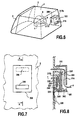
- FIGS. 6 to 8 illustrate a lighting and / or signaling device for a motor vehicle according to the invention, wherein the dehumidification means comprises an absorbent material 331.
- the absorbent material 331 comprises a first face constituting the extraction surface 232 of the humidity of the air.
- the dehumidifying means includes a power dissipator 330 comprising a heat sink 335, the absorbent material 331 including a discharge surface 334 arranged to be heatable by the power sink.
- the lighting device comprises a compartment 300 defining the dehumidification device, this compartment comprises an inlet 316 of the air outside the device and three air outlets 308, 317a and 317b. It is disposed outside the closed chamber 1, comprising the optical module 4, 5, 6 including its heat source 6, for example at the rear of the lighting and / or signaling device, on its housing 2 .
- the absorbent thus separates two air flow streams: a first flow F circulating between the first 308 and the second opening 316, and a second flow F 'flowing from the absorbent to the openings 317a and 317b of the discharge compartment.
- the extraction surface 332 gives in the first ventilation duct 314, while the evacuation surface 334 gives in the evacuation compartment 344.
- the latter comprises a heat sink 335 arranged to heat the evacuation surface 334. It is thus possible to evacuate the moisture already absorbed by the absorbent 331 via the evacuation compartment 344, while continuing to extract it in the first duct 314.
- the heat sink 335 is connected by a connection 331, particularly electrical, connected to a power source 338, such as a battery.
- the heatsink 335 can be activated independently of the light source 6.
- the compartment 330 comprises the ventilation duct 314 and the discharge compartment 344, separated by the absorbent 331.
- the compartment is formed on the one hand by the wall of the closed chamber 1 and on the other hand by a cap 301 provided with the inlet of the first conduit 316.
- the dehumidification means for example, the heatsink 335 is fixed at the wall of the housing 2, outside the chamber 1, between outwardly extending walls, and including openings 317a and 317b.
- the absorbent 331 is then placed, which then closes these walls, thus forming the evacuation compartment 344.
- the cap 301 is then placed. It would also be possible according to another embodiment, to make the compartment in the form of a removable cassette being fixed on the housing, with the ventilation duct opening into the opening of the closed chamber.
- the absorbent material 331 can be maintained as a partition by grids 340 and 341.
- baffles can also be used in all variants and embodiments with ventilation compartment, in addition to or in substitution for the semi-permeable membrane.
- the semi-permeable membrane ensures the transfer of moisture between the closed chamber and the ventilation compartment by ensuring the air drying in the projector while ensuring filtering of particles over time.
- the device according to the invention thanks to the condensation means also makes it possible to evacuate the humidity inside the projector while its ventilation holes are closed by a semi-permeable membrane.
- the lighting and / or signaling device according to the present invention may comprise one or more openings in the housing, one or more of these openings being equipped with a dehumidification means as described in the present invention.
- the different variants and embodiments can then be combined on the same projector. One can also choose the same variant for all the openings.
Landscapes
- Engineering & Computer Science (AREA)
- General Engineering & Computer Science (AREA)
- Non-Portable Lighting Devices Or Systems Thereof (AREA)
- Arrangement Of Elements, Cooling, Sealing, Or The Like Of Lighting Devices (AREA)
- Drying Of Gases (AREA)
Applications Claiming Priority (1)
| Application Number | Priority Date | Filing Date | Title |
|---|---|---|---|
| FR0956779A FR2950674B1 (fr) | 2009-09-30 | 2009-09-30 | Dispositif d'eclairage et/ou de signalisation pour vehicule automobile |
Publications (3)
| Publication Number | Publication Date |
|---|---|
| EP2306084A2 true EP2306084A2 (de) | 2011-04-06 |
| EP2306084A3 EP2306084A3 (de) | 2011-07-06 |
| EP2306084B1 EP2306084B1 (de) | 2021-09-08 |
Family
ID=42087899
Family Applications (1)
| Application Number | Title | Priority Date | Filing Date |
|---|---|---|---|
| EP10012331.4A Active EP2306084B1 (de) | 2009-09-30 | 2010-09-30 | Vorrichtung zur Beleuchtung und/oder Signalisierung für Kraftfahrzeug |
Country Status (2)
| Country | Link |
|---|---|
| EP (1) | EP2306084B1 (de) |
| FR (1) | FR2950674B1 (de) |
Cited By (8)
| Publication number | Priority date | Publication date | Assignee | Title |
|---|---|---|---|---|
| CN104896450A (zh) * | 2014-03-31 | 2015-09-09 | 豪雅冠得股份有限公司 | 光照射装置 |
| EP3135985A4 (de) * | 2014-04-23 | 2018-01-03 | Nitto Denko Corporation | Belüftungsvorrichtung und fahrzeuglampe |
| EP3382268A1 (de) * | 2017-03-28 | 2018-10-03 | ZKW Group GmbH | Fahrzeugscheinwerfer und kühlsystem |
| CN108916818A (zh) * | 2017-03-22 | 2018-11-30 | 上海汽车集团股份有限公司 | 防起雾装置、车灯、汽车及防起雾控制方法 |
| AT520396A1 (de) * | 2017-03-28 | 2019-03-15 | Zkw Group Gmbh | Fahrzeugscheinwerfer und Kühlsystem |
| CN110578910A (zh) * | 2018-06-08 | 2019-12-17 | 法雷奥照明公司 | 机动车辆前照灯抽气机 |
| EP3671022A1 (de) * | 2018-12-20 | 2020-06-24 | Valeo Vision | Automobilbeleuchtungsvorrichtung und verfahren zur steuerung eines elements davon |
| WO2020126958A1 (fr) * | 2018-12-19 | 2020-06-25 | Valeo Vision | Dispositif lumineux avec dispositif de deshumidification |
Families Citing this family (1)
| Publication number | Priority date | Publication date | Assignee | Title |
|---|---|---|---|---|
| DE102014106792A1 (de) | 2014-05-14 | 2015-11-19 | Dr. Ing. H.C. F. Porsche Aktiengesellschaft | Luftführungsvorrichtung |
Citations (2)
| Publication number | Priority date | Publication date | Assignee | Title |
|---|---|---|---|---|
| US6709493B2 (en) | 2001-03-26 | 2004-03-23 | Gore Enterprise Holdings, Inc. | Device for reducing the presence of moisture within an enclosure containing a heat source |
| US20050157514A1 (en) | 2003-12-19 | 2005-07-21 | Dr. Ing. H.C.F. Porsche Ag | Light structure |
Family Cites Families (6)
| Publication number | Priority date | Publication date | Assignee | Title |
|---|---|---|---|---|
| FR2658136B1 (fr) * | 1989-12-15 | 1994-10-21 | Renault | Appareil d'eclairage pour automobiles. |
| EP0859188A3 (de) * | 1997-02-12 | 1999-09-08 | Volkswagen Aktiengesellschaft | Scheinwerferbetauungsschutz |
| DE10213680A1 (de) * | 2002-03-27 | 2003-10-09 | Hella Kg Hueck & Co | Scheinwerfer für Fahrzeuge |
| DE10227565A1 (de) * | 2002-06-20 | 2004-01-08 | Volkswagen Ag | Scheinwerfer oder Leuchte für Fahrzeuge |
| DE102007036486A1 (de) * | 2007-08-01 | 2009-02-05 | Odelo Gmbh | Scheinwerfersystem mit gesteuerter und/oder geregelter Fördervorrichtung |
| DE102007057056A1 (de) * | 2007-11-27 | 2009-05-28 | Hella Kgaa Hueck & Co. | Scheinwerfer für ein Kraftfahrzeug mit Mitteln zum Wärmeaustausch zwischen dem Innenraum und der Außenseite des Scheinwerfers |
-
2009
- 2009-09-30 FR FR0956779A patent/FR2950674B1/fr active Active
-
2010
- 2010-09-30 EP EP10012331.4A patent/EP2306084B1/de active Active
Patent Citations (2)
| Publication number | Priority date | Publication date | Assignee | Title |
|---|---|---|---|---|
| US6709493B2 (en) | 2001-03-26 | 2004-03-23 | Gore Enterprise Holdings, Inc. | Device for reducing the presence of moisture within an enclosure containing a heat source |
| US20050157514A1 (en) | 2003-12-19 | 2005-07-21 | Dr. Ing. H.C.F. Porsche Ag | Light structure |
Cited By (15)
| Publication number | Priority date | Publication date | Assignee | Title |
|---|---|---|---|---|
| CN104896450A (zh) * | 2014-03-31 | 2015-09-09 | 豪雅冠得股份有限公司 | 光照射装置 |
| EP3135985A4 (de) * | 2014-04-23 | 2018-01-03 | Nitto Denko Corporation | Belüftungsvorrichtung und fahrzeuglampe |
| US9885456B2 (en) | 2014-04-23 | 2018-02-06 | Nitto Denko Corporation | Ventilation device and vehicular lamp |
| CN108916818A (zh) * | 2017-03-22 | 2018-11-30 | 上海汽车集团股份有限公司 | 防起雾装置、车灯、汽车及防起雾控制方法 |
| AT520396B1 (de) * | 2017-03-28 | 2019-06-15 | Zkw Group Gmbh | Fahrzeugscheinwerfer und Kühlsystem |
| AT520396A1 (de) * | 2017-03-28 | 2019-03-15 | Zkw Group Gmbh | Fahrzeugscheinwerfer und Kühlsystem |
| EP3382268A1 (de) * | 2017-03-28 | 2018-10-03 | ZKW Group GmbH | Fahrzeugscheinwerfer und kühlsystem |
| CN110578910A (zh) * | 2018-06-08 | 2019-12-17 | 法雷奥照明公司 | 机动车辆前照灯抽气机 |
| WO2020126958A1 (fr) * | 2018-12-19 | 2020-06-25 | Valeo Vision | Dispositif lumineux avec dispositif de deshumidification |
| FR3090819A1 (fr) * | 2018-12-19 | 2020-06-26 | Valeo Vision | Dispositf lumineux avec dispositif de deshumidification |
| EP3671022A1 (de) * | 2018-12-20 | 2020-06-24 | Valeo Vision | Automobilbeleuchtungsvorrichtung und verfahren zur steuerung eines elements davon |
| WO2020126526A1 (en) * | 2018-12-20 | 2020-06-25 | Valeo Vision | Automotive lighting device and method for controlling an element thereof |
| CN113227647A (zh) * | 2018-12-20 | 2021-08-06 | 法雷奥照明公司 | 机动车照明装置及用于控制其元件的方法 |
| US11603978B2 (en) | 2018-12-20 | 2023-03-14 | Valeo Vision | Automotive lighting device and method for controlling an element thereof |
| CN113227647B (zh) * | 2018-12-20 | 2024-02-23 | 法雷奥照明公司 | 机动车照明装置及用于控制其元件的方法 |
Also Published As
| Publication number | Publication date |
|---|---|
| FR2950674B1 (fr) | 2012-08-31 |
| EP2306084B1 (de) | 2021-09-08 |
| FR2950674A1 (fr) | 2011-04-01 |
| EP2306084A3 (de) | 2011-07-06 |
Similar Documents
| Publication | Publication Date | Title |
|---|---|---|
| EP2306084B1 (de) | Vorrichtung zur Beleuchtung und/oder Signalisierung für Kraftfahrzeug | |
| EP2014972B1 (de) | Vorrichtung zur Behandlung von Feuchtigkeit im Innern eines Kraftfahrzeug-Scheinwerfers und mit einer solchen Vorrichtung ausgestatteter Scheinwerfer | |
| EP2032440B1 (de) | Passives kapillargepumptes diphasisches flüssigkeitskreis-wärmesteuerungsgerät mit wärmeleistung | |
| EP0692086B1 (de) | Chemischer reaktor, kältemaschine und behälter ausgestattet mit diesem reaktor und reagenzpatrone dafür | |
| FR2968839A1 (fr) | Pack batterie haute tension etanche | |
| EP2476301B1 (de) | System zur thermischen steuerung eines geräts | |
| EP1635682B1 (de) | Kochgerätkondensator | |
| FR2844035A1 (fr) | Procede et systeme d'extraction et de rejet de la vapeur d'eau contenue dans l'air d'un vehicule spatial | |
| EP3014661B1 (de) | Solarmodul mit vereinfachter feuchtigkeitspegelregulierung | |
| CH639517A5 (en) | Cooling device for an installation containing electronic equipment | |
| EP2604915B1 (de) | Vorrichtung zur Beleuchtung und/oder Signalisierung, und Kraftfahrzeug, das eine solche Vorrichtung umfasst | |
| EP2981781B1 (de) | Wärmerohr mit abgeschirmtem gasstecker | |
| EP1401252B1 (de) | Gekühlter Elektronikschrank, insbesondere für Fernsprechanlagen | |
| EP2532949B1 (de) | Beleuchtungs- und/oder Signalisierungsvorrichtung mit integriertem Wärmeableiter | |
| WO2007144024A1 (fr) | Dispositif a echanges thermiques | |
| FR2951816A1 (fr) | Secheur industriel a pompe a chaleur. | |
| EP3198215B1 (de) | Wärmetauschersystem mit verbesserter leistung und verbesserter kompaktheit | |
| FR2795459A1 (fr) | Dispositif de refroidissement d'un ventilateur de circulation d'air monte dans un caisson | |
| EP1889527B1 (de) | Belüftungssystem | |
| FR3124325A1 (fr) | Dispositif de régulation thermique d’au moins un composant électrique et/ou électronique. | |
| FR2481427A1 (fr) | Capteur solaire | |
| FR2616523A1 (fr) | Installation frigorifique autonome et modulaire, pour vehicule automobile a moteur thermique et procede de fonctionnement d'une telle installation | |
| EP1970640A1 (de) | Elektrisches Heizgerät | |
| FR2666140A1 (fr) | Pompe a chaleur a cycle de desorption-adsorption a fonctionnement pseudo-continu. | |
| EP2177821A1 (de) | Scheinwerfer mit Vorrichtung zur Abfuhr von Hitze |
Legal Events
| Date | Code | Title | Description |
|---|---|---|---|
| PUAI | Public reference made under article 153(3) epc to a published international application that has entered the european phase |
Free format text: ORIGINAL CODE: 0009012 |
|
| AK | Designated contracting states |
Kind code of ref document: A2 Designated state(s): AL AT BE BG CH CY CZ DE DK EE ES FI FR GB GR HR HU IE IS IT LI LT LU LV MC MK MT NL NO PL PT RO SE SI SK SM TR |
|
| AX | Request for extension of the european patent |
Extension state: BA ME RS |
|
| PUAL | Search report despatched |
Free format text: ORIGINAL CODE: 0009013 |
|
| AK | Designated contracting states |
Kind code of ref document: A3 Designated state(s): AL AT BE BG CH CY CZ DE DK EE ES FI FR GB GR HR HU IE IS IT LI LT LU LV MC MK MT NL NO PL PT RO SE SI SK SM TR |
|
| AX | Request for extension of the european patent |
Extension state: BA ME RS |
|
| 17P | Request for examination filed |
Effective date: 20111222 |
|
| RIC1 | Information provided on ipc code assigned before grant |
Ipc: F21W 101/10 20060101ALN20120309BHEP Ipc: F21V 31/03 20060101AFI20120309BHEP |
|
| STAA | Information on the status of an ep patent application or granted ep patent |
Free format text: STATUS: EXAMINATION IS IN PROGRESS |
|
| 17Q | First examination report despatched |
Effective date: 20191108 |
|
| REG | Reference to a national code |
Ref country code: DE Ref legal event code: R079 Ref document number: 602010067549 Country of ref document: DE Free format text: PREVIOUS MAIN CLASS: F21V0031030000 Ipc: F21S0045300000 |
|
| RIC1 | Information provided on ipc code assigned before grant |
Ipc: F21S 45/33 20180101ALI20210301BHEP Ipc: F21V 31/03 20060101ALI20210301BHEP Ipc: F21S 45/30 20180101AFI20210301BHEP |
|
| GRAP | Despatch of communication of intention to grant a patent |
Free format text: ORIGINAL CODE: EPIDOSNIGR1 |
|
| STAA | Information on the status of an ep patent application or granted ep patent |
Free format text: STATUS: GRANT OF PATENT IS INTENDED |
|
| INTG | Intention to grant announced |
Effective date: 20210428 |
|
| GRAS | Grant fee paid |
Free format text: ORIGINAL CODE: EPIDOSNIGR3 |
|
| GRAA | (expected) grant |
Free format text: ORIGINAL CODE: 0009210 |
|
| STAA | Information on the status of an ep patent application or granted ep patent |
Free format text: STATUS: THE PATENT HAS BEEN GRANTED |
|
| AK | Designated contracting states |
Kind code of ref document: B1 Designated state(s): AL AT BE BG CH CY CZ DE DK EE ES FI FR GB GR HR HU IE IS IT LI LT LU LV MC MK MT NL NO PL PT RO SE SI SK SM TR |
|
| REG | Reference to a national code |
Ref country code: GB Ref legal event code: FG4D Free format text: NOT ENGLISH |
|
| REG | Reference to a national code |
Ref country code: AT Ref legal event code: REF Ref document number: 1428902 Country of ref document: AT Kind code of ref document: T Effective date: 20210915 Ref country code: CH Ref legal event code: EP |
|
| REG | Reference to a national code |
Ref country code: IE Ref legal event code: FG4D Free format text: LANGUAGE OF EP DOCUMENT: FRENCH |
|
| REG | Reference to a national code |
Ref country code: DE Ref legal event code: R096 Ref document number: 602010067549 Country of ref document: DE |
|
| REG | Reference to a national code |
Ref country code: LT Ref legal event code: MG9D |
|
| REG | Reference to a national code |
Ref country code: NL Ref legal event code: MP Effective date: 20210908 |
|
| PG25 | Lapsed in a contracting state [announced via postgrant information from national office to epo] |
Ref country code: HR Free format text: LAPSE BECAUSE OF FAILURE TO SUBMIT A TRANSLATION OF THE DESCRIPTION OR TO PAY THE FEE WITHIN THE PRESCRIBED TIME-LIMIT Effective date: 20210908 Ref country code: SE Free format text: LAPSE BECAUSE OF FAILURE TO SUBMIT A TRANSLATION OF THE DESCRIPTION OR TO PAY THE FEE WITHIN THE PRESCRIBED TIME-LIMIT Effective date: 20210908 Ref country code: BG Free format text: LAPSE BECAUSE OF FAILURE TO SUBMIT A TRANSLATION OF THE DESCRIPTION OR TO PAY THE FEE WITHIN THE PRESCRIBED TIME-LIMIT Effective date: 20211208 Ref country code: LT Free format text: LAPSE BECAUSE OF FAILURE TO SUBMIT A TRANSLATION OF THE DESCRIPTION OR TO PAY THE FEE WITHIN THE PRESCRIBED TIME-LIMIT Effective date: 20210908 Ref country code: NO Free format text: LAPSE BECAUSE OF FAILURE TO SUBMIT A TRANSLATION OF THE DESCRIPTION OR TO PAY THE FEE WITHIN THE PRESCRIBED TIME-LIMIT Effective date: 20211208 Ref country code: FI Free format text: LAPSE BECAUSE OF FAILURE TO SUBMIT A TRANSLATION OF THE DESCRIPTION OR TO PAY THE FEE WITHIN THE PRESCRIBED TIME-LIMIT Effective date: 20210908 Ref country code: ES Free format text: LAPSE BECAUSE OF FAILURE TO SUBMIT A TRANSLATION OF THE DESCRIPTION OR TO PAY THE FEE WITHIN THE PRESCRIBED TIME-LIMIT Effective date: 20210908 |
|
| REG | Reference to a national code |
Ref country code: AT Ref legal event code: MK05 Ref document number: 1428902 Country of ref document: AT Kind code of ref document: T Effective date: 20210908 |
|
| PG25 | Lapsed in a contracting state [announced via postgrant information from national office to epo] |
Ref country code: LV Free format text: LAPSE BECAUSE OF FAILURE TO SUBMIT A TRANSLATION OF THE DESCRIPTION OR TO PAY THE FEE WITHIN THE PRESCRIBED TIME-LIMIT Effective date: 20210908 Ref country code: GR Free format text: LAPSE BECAUSE OF FAILURE TO SUBMIT A TRANSLATION OF THE DESCRIPTION OR TO PAY THE FEE WITHIN THE PRESCRIBED TIME-LIMIT Effective date: 20211209 |
|
| PG25 | Lapsed in a contracting state [announced via postgrant information from national office to epo] |
Ref country code: AT Free format text: LAPSE BECAUSE OF FAILURE TO SUBMIT A TRANSLATION OF THE DESCRIPTION OR TO PAY THE FEE WITHIN THE PRESCRIBED TIME-LIMIT Effective date: 20210908 |
|
| REG | Reference to a national code |
Ref country code: CH Ref legal event code: PL |
|
| REG | Reference to a national code |
Ref country code: BE Ref legal event code: MM Effective date: 20210930 |
|
| PG25 | Lapsed in a contracting state [announced via postgrant information from national office to epo] |
Ref country code: IS Free format text: LAPSE BECAUSE OF FAILURE TO SUBMIT A TRANSLATION OF THE DESCRIPTION OR TO PAY THE FEE WITHIN THE PRESCRIBED TIME-LIMIT Effective date: 20220108 Ref country code: SM Free format text: LAPSE BECAUSE OF FAILURE TO SUBMIT A TRANSLATION OF THE DESCRIPTION OR TO PAY THE FEE WITHIN THE PRESCRIBED TIME-LIMIT Effective date: 20210908 Ref country code: SK Free format text: LAPSE BECAUSE OF FAILURE TO SUBMIT A TRANSLATION OF THE DESCRIPTION OR TO PAY THE FEE WITHIN THE PRESCRIBED TIME-LIMIT Effective date: 20210908 Ref country code: RO Free format text: LAPSE BECAUSE OF FAILURE TO SUBMIT A TRANSLATION OF THE DESCRIPTION OR TO PAY THE FEE WITHIN THE PRESCRIBED TIME-LIMIT Effective date: 20210908 Ref country code: PT Free format text: LAPSE BECAUSE OF FAILURE TO SUBMIT A TRANSLATION OF THE DESCRIPTION OR TO PAY THE FEE WITHIN THE PRESCRIBED TIME-LIMIT Effective date: 20220110 Ref country code: PL Free format text: LAPSE BECAUSE OF FAILURE TO SUBMIT A TRANSLATION OF THE DESCRIPTION OR TO PAY THE FEE WITHIN THE PRESCRIBED TIME-LIMIT Effective date: 20210908 Ref country code: NL Free format text: LAPSE BECAUSE OF FAILURE TO SUBMIT A TRANSLATION OF THE DESCRIPTION OR TO PAY THE FEE WITHIN THE PRESCRIBED TIME-LIMIT Effective date: 20210908 Ref country code: EE Free format text: LAPSE BECAUSE OF FAILURE TO SUBMIT A TRANSLATION OF THE DESCRIPTION OR TO PAY THE FEE WITHIN THE PRESCRIBED TIME-LIMIT Effective date: 20210908 Ref country code: CZ Free format text: LAPSE BECAUSE OF FAILURE TO SUBMIT A TRANSLATION OF THE DESCRIPTION OR TO PAY THE FEE WITHIN THE PRESCRIBED TIME-LIMIT Effective date: 20210908 Ref country code: AL Free format text: LAPSE BECAUSE OF FAILURE TO SUBMIT A TRANSLATION OF THE DESCRIPTION OR TO PAY THE FEE WITHIN THE PRESCRIBED TIME-LIMIT Effective date: 20210908 |
|
| REG | Reference to a national code |
Ref country code: DE Ref legal event code: R097 Ref document number: 602010067549 Country of ref document: DE |
|
| PG25 | Lapsed in a contracting state [announced via postgrant information from national office to epo] |
Ref country code: MC Free format text: LAPSE BECAUSE OF FAILURE TO SUBMIT A TRANSLATION OF THE DESCRIPTION OR TO PAY THE FEE WITHIN THE PRESCRIBED TIME-LIMIT Effective date: 20210908 |
|
| PLBE | No opposition filed within time limit |
Free format text: ORIGINAL CODE: 0009261 |
|
| STAA | Information on the status of an ep patent application or granted ep patent |
Free format text: STATUS: NO OPPOSITION FILED WITHIN TIME LIMIT |
|
| PG25 | Lapsed in a contracting state [announced via postgrant information from national office to epo] |
Ref country code: LU Free format text: LAPSE BECAUSE OF NON-PAYMENT OF DUE FEES Effective date: 20210930 Ref country code: IE Free format text: LAPSE BECAUSE OF NON-PAYMENT OF DUE FEES Effective date: 20210930 Ref country code: DK Free format text: LAPSE BECAUSE OF FAILURE TO SUBMIT A TRANSLATION OF THE DESCRIPTION OR TO PAY THE FEE WITHIN THE PRESCRIBED TIME-LIMIT Effective date: 20210908 Ref country code: BE Free format text: LAPSE BECAUSE OF NON-PAYMENT OF DUE FEES Effective date: 20210930 |
|
| 26N | No opposition filed |
Effective date: 20220609 |
|
| GBPC | Gb: european patent ceased through non-payment of renewal fee |
Effective date: 20211208 |
|
| PG25 | Lapsed in a contracting state [announced via postgrant information from national office to epo] |
Ref country code: SI Free format text: LAPSE BECAUSE OF FAILURE TO SUBMIT A TRANSLATION OF THE DESCRIPTION OR TO PAY THE FEE WITHIN THE PRESCRIBED TIME-LIMIT Effective date: 20210908 Ref country code: LI Free format text: LAPSE BECAUSE OF NON-PAYMENT OF DUE FEES Effective date: 20210930 Ref country code: CH Free format text: LAPSE BECAUSE OF NON-PAYMENT OF DUE FEES Effective date: 20210930 |
|
| PG25 | Lapsed in a contracting state [announced via postgrant information from national office to epo] |
Ref country code: GB Free format text: LAPSE BECAUSE OF NON-PAYMENT OF DUE FEES Effective date: 20211208 |
|
| PG25 | Lapsed in a contracting state [announced via postgrant information from national office to epo] |
Ref country code: IT Free format text: LAPSE BECAUSE OF FAILURE TO SUBMIT A TRANSLATION OF THE DESCRIPTION OR TO PAY THE FEE WITHIN THE PRESCRIBED TIME-LIMIT Effective date: 20210908 |
|
| PG25 | Lapsed in a contracting state [announced via postgrant information from national office to epo] |
Ref country code: HU Free format text: LAPSE BECAUSE OF FAILURE TO SUBMIT A TRANSLATION OF THE DESCRIPTION OR TO PAY THE FEE WITHIN THE PRESCRIBED TIME-LIMIT; INVALID AB INITIO Effective date: 20100930 Ref country code: CY Free format text: LAPSE BECAUSE OF FAILURE TO SUBMIT A TRANSLATION OF THE DESCRIPTION OR TO PAY THE FEE WITHIN THE PRESCRIBED TIME-LIMIT Effective date: 20210908 |
|
| P01 | Opt-out of the competence of the unified patent court (upc) registered |
Effective date: 20230528 |
|
| PG25 | Lapsed in a contracting state [announced via postgrant information from national office to epo] |
Ref country code: MK Free format text: LAPSE BECAUSE OF FAILURE TO SUBMIT A TRANSLATION OF THE DESCRIPTION OR TO PAY THE FEE WITHIN THE PRESCRIBED TIME-LIMIT Effective date: 20210908 |
|
| PG25 | Lapsed in a contracting state [announced via postgrant information from national office to epo] |
Ref country code: TR Free format text: LAPSE BECAUSE OF FAILURE TO SUBMIT A TRANSLATION OF THE DESCRIPTION OR TO PAY THE FEE WITHIN THE PRESCRIBED TIME-LIMIT Effective date: 20210908 |
|
| PG25 | Lapsed in a contracting state [announced via postgrant information from national office to epo] |
Ref country code: MT Free format text: LAPSE BECAUSE OF FAILURE TO SUBMIT A TRANSLATION OF THE DESCRIPTION OR TO PAY THE FEE WITHIN THE PRESCRIBED TIME-LIMIT Effective date: 20210908 |
|
| PGFP | Annual fee paid to national office [announced via postgrant information from national office to epo] |
Ref country code: DE Payment date: 20240912 Year of fee payment: 15 |
|
| PGFP | Annual fee paid to national office [announced via postgrant information from national office to epo] |
Ref country code: FR Payment date: 20240925 Year of fee payment: 15 |