EP2306106B1 - Système de renouvellement d'air pour aérer au moins une pièce dans un bâtiment - Google Patents
Système de renouvellement d'air pour aérer au moins une pièce dans un bâtiment Download PDFInfo
- Publication number
- EP2306106B1 EP2306106B1 EP10185578.1A EP10185578A EP2306106B1 EP 2306106 B1 EP2306106 B1 EP 2306106B1 EP 10185578 A EP10185578 A EP 10185578A EP 2306106 B1 EP2306106 B1 EP 2306106B1
- Authority
- EP
- European Patent Office
- Prior art keywords
- air
- exchange device
- building
- air exchange
- wall
- Prior art date
- Legal status (The legal status is an assumption and is not a legal conclusion. Google has not performed a legal analysis and makes no representation as to the accuracy of the status listed.)
- Expired - Lifetime
Links
- 238000009423 ventilation Methods 0.000 title claims abstract description 33
- 238000002485 combustion reaction Methods 0.000 description 9
- 239000000779 smoke Substances 0.000 description 9
- 239000007789 gas Substances 0.000 description 8
- 238000005192 partition Methods 0.000 description 5
- 238000001816 cooling Methods 0.000 description 4
- 238000010438 heat treatment Methods 0.000 description 4
- QVGXLLKOCUKJST-UHFFFAOYSA-N atomic oxygen Chemical compound [O] QVGXLLKOCUKJST-UHFFFAOYSA-N 0.000 description 3
- 239000001301 oxygen Substances 0.000 description 3
- 229910052760 oxygen Inorganic materials 0.000 description 3
- 108010076504 Protein Sorting Signals Proteins 0.000 description 2
- 238000004378 air conditioning Methods 0.000 description 2
- 238000010276 construction Methods 0.000 description 2
- 239000007788 liquid Substances 0.000 description 2
- 239000002184 metal Substances 0.000 description 2
- 229910052751 metal Inorganic materials 0.000 description 2
- XLYOFNOQVPJJNP-UHFFFAOYSA-N water Substances O XLYOFNOQVPJJNP-UHFFFAOYSA-N 0.000 description 2
- 238000004891 communication Methods 0.000 description 1
- 238000009833 condensation Methods 0.000 description 1
- 230000005494 condensation Effects 0.000 description 1
- 239000013505 freshwater Substances 0.000 description 1
- 230000004941 influx Effects 0.000 description 1
- 239000000463 material Substances 0.000 description 1
- 230000001473 noxious effect Effects 0.000 description 1
- 238000011084 recovery Methods 0.000 description 1
- 230000029058 respiratory gaseous exchange Effects 0.000 description 1
- 230000009182 swimming Effects 0.000 description 1
- 239000002341 toxic gas Substances 0.000 description 1
Images




Classifications
-
- F—MECHANICAL ENGINEERING; LIGHTING; HEATING; WEAPONS; BLASTING
- F24—HEATING; RANGES; VENTILATING
- F24F—AIR-CONDITIONING; AIR-HUMIDIFICATION; VENTILATION; USE OF AIR CURRENTS FOR SCREENING
- F24F12/00—Use of energy recovery systems in air conditioning, ventilation or screening
- F24F12/001—Use of energy recovery systems in air conditioning, ventilation or screening with heat-exchange between supplied and exhausted air
- F24F12/006—Use of energy recovery systems in air conditioning, ventilation or screening with heat-exchange between supplied and exhausted air using an air-to-air heat exchanger
-
- F—MECHANICAL ENGINEERING; LIGHTING; HEATING; WEAPONS; BLASTING
- F24—HEATING; RANGES; VENTILATING
- F24F—AIR-CONDITIONING; AIR-HUMIDIFICATION; VENTILATION; USE OF AIR CURRENTS FOR SCREENING
- F24F11/00—Control or safety arrangements
- F24F11/0008—Control or safety arrangements for air-humidification
-
- F—MECHANICAL ENGINEERING; LIGHTING; HEATING; WEAPONS; BLASTING
- F24—HEATING; RANGES; VENTILATING
- F24F—AIR-CONDITIONING; AIR-HUMIDIFICATION; VENTILATION; USE OF AIR CURRENTS FOR SCREENING
- F24F11/00—Control or safety arrangements
- F24F11/70—Control systems characterised by their outputs; Constructional details thereof
- F24F11/72—Control systems characterised by their outputs; Constructional details thereof for controlling the supply of treated air, e.g. its pressure
- F24F11/74—Control systems characterised by their outputs; Constructional details thereof for controlling the supply of treated air, e.g. its pressure for controlling air flow rate or air velocity
- F24F11/77—Control systems characterised by their outputs; Constructional details thereof for controlling the supply of treated air, e.g. its pressure for controlling air flow rate or air velocity by controlling the speed of ventilators
-
- F—MECHANICAL ENGINEERING; LIGHTING; HEATING; WEAPONS; BLASTING
- F24—HEATING; RANGES; VENTILATING
- F24F—AIR-CONDITIONING; AIR-HUMIDIFICATION; VENTILATION; USE OF AIR CURRENTS FOR SCREENING
- F24F7/00—Ventilation
- F24F7/007—Ventilation with forced flow
- F24F7/013—Ventilation with forced flow using wall or window fans, displacing air through the wall or window
-
- F—MECHANICAL ENGINEERING; LIGHTING; HEATING; WEAPONS; BLASTING
- F24—HEATING; RANGES; VENTILATING
- F24F—AIR-CONDITIONING; AIR-HUMIDIFICATION; VENTILATION; USE OF AIR CURRENTS FOR SCREENING
- F24F11/00—Control or safety arrangements
- F24F11/0001—Control or safety arrangements for ventilation
- F24F2011/0002—Control or safety arrangements for ventilation for admittance of outside air
-
- F—MECHANICAL ENGINEERING; LIGHTING; HEATING; WEAPONS; BLASTING
- F24—HEATING; RANGES; VENTILATING
- F24F—AIR-CONDITIONING; AIR-HUMIDIFICATION; VENTILATION; USE OF AIR CURRENTS FOR SCREENING
- F24F12/00—Use of energy recovery systems in air conditioning, ventilation or screening
- F24F12/001—Use of energy recovery systems in air conditioning, ventilation or screening with heat-exchange between supplied and exhausted air
- F24F2012/008—Use of energy recovery systems in air conditioning, ventilation or screening with heat-exchange between supplied and exhausted air cyclic routing supply and exhaust air
-
- F—MECHANICAL ENGINEERING; LIGHTING; HEATING; WEAPONS; BLASTING
- F24—HEATING; RANGES; VENTILATING
- F24F—AIR-CONDITIONING; AIR-HUMIDIFICATION; VENTILATION; USE OF AIR CURRENTS FOR SCREENING
- F24F2110/00—Control inputs relating to air properties
- F24F2110/30—Velocity
-
- F—MECHANICAL ENGINEERING; LIGHTING; HEATING; WEAPONS; BLASTING
- F24—HEATING; RANGES; VENTILATING
- F24F—AIR-CONDITIONING; AIR-HUMIDIFICATION; VENTILATION; USE OF AIR CURRENTS FOR SCREENING
- F24F2110/00—Control inputs relating to air properties
- F24F2110/40—Pressure, e.g. wind pressure
-
- Y—GENERAL TAGGING OF NEW TECHNOLOGICAL DEVELOPMENTS; GENERAL TAGGING OF CROSS-SECTIONAL TECHNOLOGIES SPANNING OVER SEVERAL SECTIONS OF THE IPC; TECHNICAL SUBJECTS COVERED BY FORMER USPC CROSS-REFERENCE ART COLLECTIONS [XRACs] AND DIGESTS
- Y02—TECHNOLOGIES OR APPLICATIONS FOR MITIGATION OR ADAPTATION AGAINST CLIMATE CHANGE
- Y02B—CLIMATE CHANGE MITIGATION TECHNOLOGIES RELATED TO BUILDINGS, e.g. HOUSING, HOUSE APPLIANCES OR RELATED END-USER APPLICATIONS
- Y02B30/00—Energy efficient heating, ventilation or air conditioning [HVAC]
- Y02B30/56—Heat recovery units
-
- Y—GENERAL TAGGING OF NEW TECHNOLOGICAL DEVELOPMENTS; GENERAL TAGGING OF CROSS-SECTIONAL TECHNOLOGIES SPANNING OVER SEVERAL SECTIONS OF THE IPC; TECHNICAL SUBJECTS COVERED BY FORMER USPC CROSS-REFERENCE ART COLLECTIONS [XRACs] AND DIGESTS
- Y02—TECHNOLOGIES OR APPLICATIONS FOR MITIGATION OR ADAPTATION AGAINST CLIMATE CHANGE
- Y02B—CLIMATE CHANGE MITIGATION TECHNOLOGIES RELATED TO BUILDINGS, e.g. HOUSING, HOUSE APPLIANCES OR RELATED END-USER APPLICATIONS
- Y02B30/00—Energy efficient heating, ventilation or air conditioning [HVAC]
- Y02B30/70—Efficient control or regulation technologies, e.g. for control of refrigerant flow, motor or heating
Definitions
- the invention relates to an air exchange system for the ventilation of at least one room of a building with at least one air exchange device.
- heat exchangers which transfer heat in the direction of a temperature gradient between the two air streams.
- tube bundle, finned tube, plate, spiral, spiral tube double-jacket and coil heat exchanger There are known tube bundle, finned tube, plate, spiral, spiral tube double-jacket and coil heat exchanger.
- Such heat exchangers are often components of air exchange devices, which are also referred to as recuperators or as recuperative devices.
- This air conditioning system has an air conditioner with a supply air fan and an exhaust air treatment system with an exhaust fan.
- a heat exchanger of the exhaust treatment plant is connected via a feedback pipe to a heat exchanger of the air conditioner.
- From the CH 599 510 is a device for heat recovery, especially for a swimming pool, known.
- This device has a first heat exchanger stage with a heat exchanger, a supply air fan and an exhaust fan and a second heat exchanger stage, are used in the various exhaust air streams for heating fresh water.
- each air exchange device provided in the air exchange system already provides taken for itself for a removal of spent exhaust air and for an influx of fresh supply air.
- an air movement is created between that air exchange device which has only one supply air fan and the one air exchange device which only comprises one exhaust air fan. This air movement is directed from the air exchange device with the supply air fan to the air exchange device with the exhaust air fan. This air movement ensures that even areas that are not in the immediate vicinity of the air exchange devices are supplied with fresh outdoor air.
- Another basic idea of the invention is that in at least one air exchange device of the supply air fan and exhaust air fan are so adjustable that the supply air is greater than the exhaust air flow and that in at least one other air exchange device of the supply air fan and the Exhaust air fans are adjustable so that the exhaust air flow is greater than the supply air flow is formed.
- Such an adjustability of the volume flows of the air volumes supplied by the supply air fan and by the exhaust air fan allows the air exchange of the individual air exchange devices and thus the air exchange of the air exchange system to be adapted individually to the environment.
- air movement is created between the individual air exchange devices. As a result, an air exchange is ensured even in those areas that are not in the immediate vicinity of one of the air exchange devices.
- the intensity of the air movement between the individual air exchange devices can be adjusted accurately and as needed by changing the rotational frequencies of the fans and / or the angle of attack of the fan blades.
- the first air exchange device may operate, for example, with a ratio of the exhaust air flow volume to the supply air flow volume of 40% / 60% and the second air exchange device with a ratio of the exhaust air flow volume to the supply air flow volume of 60% / 40% become.
- a change of direction The air movement between the air exchange devices can be achieved by reversing the ratio of the exhaust air flow volume to the supply air flow volume in both air exchange devices.
- the invention also includes air exchange systems having three or more air exchange devices. Such air exchange systems are also referred to as network versions.
- the invention also relates to an above-described air exchange system having at least one outer wall of the building.
- the rear sides of the air exchange devices are attached to at least one outer wall of the building.
- On or in the outer wall pipe connections are provided, which extend to the outside of the building.
- Fresh unused external air into the air exchange devices and spent exhaust air from the air exchange devices can reach the outside of the building via these pipe connections. With such mounted air exchange devices, a direct and effective air exchange of the spent exhaust air is achieved with fresh outdoor air.
- At least one air exchange device is attached to a first outer wall and at least one further air exchange device is attached to a second outer wall.
- the building section lying between the two walls is continuously supplied with fresh and heated supply air.
- the rooms between the two outer walls of the building are also continuously flushed with fresh, heated outside air. It must be ensured that the air movement between these rooms is not interrupted, for example, by a closed door.
- At least one passage in particular a staircase, a door or a corridor and / or at least one further space is arranged between the first outer wall and the second outer wall, these are likewise continuously supplied with fresh, heated outside air. This is also called cross ventilation.
- the air exchange devices are connected to a control unit, in particular to a computer.
- a control unit in particular to a computer.
- the rotational frequencies of the fan wheels and / or the angle of attack of the fan blades for the supply air fan and exhaust air fan of the individual air exchange devices can be set individually and precisely.
- FIG. 1 shows a schematic representation of a plan view of an air exchange device 1 according to an embodiment.
- the air exchange device 1 is enclosed by a square housing 3. At the in FIG. 1 shown top view of the front of the housing 3 is removed.
- the housing 3 has plastic in the exemplary embodiment, but can also be manufactured from other materials.
- a square plate heat exchanger 2 is arranged, in particular of good heat-conducting metal, wherein in the plan view according to FIG. 1 only the top plate of the plate heat exchanger 2 is visible.
- the side length of the plate heat exchanger 2 corresponds to almost half the side length of the housing 3.
- the plate heat exchanger 2 is arranged at an angle of 45 ° with respect to the housing 3 is rotated.
- a circular outside air inlet opening 4 is provided in the bottom of the housing 3.
- a curved wall which terminates at the upper and at the lower end of the right upper side of the plate heat exchanger 2.
- a similarly shaped wall is provided, which terminates at the upper and at the lower end of the left upper side of the plate heat exchanger 2.
- an opening is provided which is arranged when placing the front of the housing 3 within this wall.
- an exhaust air fan housing 5 with a Fortluftradiallconer 6 and arranged between the exhaust air fan 6 and the plate heat exchanger 2 funnel 8 is provided on the right lower side of the plate heat exchanger 2.
- the funnel 8 sits on the entire width of the lower right side the plate heat exchanger 2 and tapers over a distance about one-eighth of the side length of the plate heat exchanger 2 by an angle of 30 °.
- the exhaust air radial fan 6 starts, from the plan view in FIG. 1 only the panel is recognizable.
- the axis of rotation of the exhaust air fan 6 is aligned perpendicular to the height of the center of the lower right side of the plate heat exchanger 2.
- the diameter or the width of the exhaust air ventilator 6 corresponds approximately to the outlet side of the funnel 8.
- the depth of the exhaust air ventilator 6 corresponds approximately to half its width.
- the exhaust air flywheel fan 6 is enclosed by an exhaust fan housing 5, which on its underside a in FIG. 1 Has shown in dashed lines, rectangular exhaust air outlet 7. This exhaust air outlet opening 7 is arranged offset from the middle of the exhaust air ventilation fan 6 starting slightly to the top right.
- Zu Kunststoffansaugradialliler 10 On the left lower side of the plate heat exchanger 2 is an enclosed by a thin air inlet fan housing 9 Zu Kunststoffansaugradialldesigner 10 at.
- the rotation axis of the Zu Kunststoffansaugradiallilers 10 is disposed orthogonal to the left lower side of the plate heat exchanger 2 at the level of the center.
- the diameter or width of the Zuutzansaugradiallilers 10 corresponds approximately to the side length of the plate heat exchanger 2, its depth corresponds to about half its width.
- Zu Kunststoffansaugradiallflecters 10 In the left upper portion of Zu povertyansaugradiallconers 10 is a rectangular Zu Kunststoffeinlouö réelle arranged through which a plurality of fan blades of Zu Kunststoffansaugradiallilers 10 can be seen. These are parallel to the axis of rotation of Zu Kunststoffansaugradiallillustallilers in the embodiment 10, but may also be oblique to this or curved.
- a first cut line A-A passes through the lower left and right upper corners of the housing 3.
- a further cut line B-B passes through the upper left and lower right corners of the housing 3.
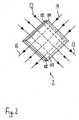
- FIG. 2 shows a schematic, perspective view of the in FIG. 1 shown plate heat exchanger 2 and a graphical illustration of the plate heat exchanger 2 by flowing air streams according to the embodiment.
- the plate heat exchanger 2 comprises three stacked, square metal plates, which in FIG. 2 are each shown standing on a corner.
- the lower and middle plates of the plate heat exchanger 2 have a slit-like hot air inlet 102 on the upper left side and a slit-like cold air outlet 103 on the lower right side.
- the lower plate On the left lower and on the right upper side, the lower plate is connected to the middle plate of the plate heat exchanger 2 each having a continuous wall.
- On the right upper side of the plate heat exchanger 2 there is a slot-like cold air inlet 104 between the middle and upper plates.
- a wall is provided between the middle and the upper plate.
- an exhaust air flow 12 flows into the warm air inlet 102, flows through the plate heat exchanger 2 and exits on the opposite side as exhaust air stream 13 from the cold air outlet 103.
- the case of the exhaust air flow 12 through the area of the plate heat exchanger 2 is also referred to as a cooling side.
- An outside air flow 14 enters the plate heat exchanger 2 through the cold air inlet 104, flows through it and exits the hot air outlet 105 as a supply air flow 15 on the opposite side.
- the area of the plate heat exchanger 2 through which the outside air flow 14 flows is also called the heating side of the plate heat exchanger 2.
- FIG. 3 shows a schematic representation of a cross section along the section line AA attached to an outer wall 17 air exchange device 1 according to the embodiment. In FIG. 3 is considered the heating side of the plate heat exchanger 2.
- the air exchange device 1 rests with the back of its housing 3 on the front of the outer wall 17 and is accordingly in the building interior. From the cross-sectional view in FIG. 3 It can be seen that the diagonal height of the air exchange system 1 corresponds approximately to three times its depth.
- the interior of the housing 3 is divided into a topmost arranged outside air inlet area, in a centrally located plate heat exchanger area and in a lowermost Zu Kunststoffauslenfin Kunststoffe.
- the outside air inlet opening 4 is formed on the rear side of the housing 3, to which a horizontal outside air supply pipe 18 connects on the outside wall side.
- the plate heat exchanger 2 is arranged, the three parallel, as shown in FIG FIG. 3 From top to bottom extending air ducts.
- the plate heat exchanger 2 shown here corresponds in principle to the plate heat exchanger 2 FIG. 2 , but has eight plates arranged one above the other.
- a supply air impeller 16 is disposed within the supply air fan housing 9.
- the supply air fan 16 is arranged horizontally in the middle.
- a Zuluftauslouö réelle 11 is provided in the front of the housing 3 and in the left side of the supply air fan housing 9, whose height corresponds to the width of the fan blades.
- the supply air fan housing starts at the left and at the right end of the underside of the plate heat exchanger 2, runs vertically downwards on both sides and has a horizontal underside directly in front of the underside of the housing 3.
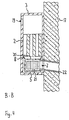
- FIG. 4 shows a schematic representation of a cross section along the section line BB of the attached to the outer wall 17 air exchange system 1 according to the embodiment.
- the cooling side of the plate heat exchanger 2 is considered.
- the interior of the housing 3 is divided into an upper exhaust air inlet area, a central plate heat exchanger area and a lower exhaust air outlet area.
- an exhaust air inlet opening 19 is provided on the front side of the housing 3.
- the plate heat exchanger region of the plate heat exchanger 2 is arranged, the four parallel, having vertically extending air ducts.
- the plate heat exchanger 2 shown here corresponds in principle to the plate heat exchanger 2 FIG. 2 , but has eight plates arranged one above the other.
- the exhaust air discharge area includes one in construction, in size and in alignment with the one in FIG FIG. 3 shown Zu Kunststofflwillerrad 16 identical Fortllibraryllibraryerrad 21.
- the exhaust air fan 21 is centered within the exhaust fan housing 5 is arranged.
- an exhaust air outlet opening 7 At this exhaust air outlet 7 is an exhaust air outlet pipe 22, which extends slightly inclined to the right below. Centered on the top of the exhaust air fan housing 5, an exhaust air supply opening 20 is provided whose width corresponds to approximately one third of the total width of the exhaust air fan housing 5. Between the left and the right end of the underside of the plate heat exchanger 2 and the left and right sides of the top of the exhaust air fan housing 5, the hopper 8 is arranged.
- the exhaust air fan 6 and the exhaust air fan 21 sucks by the movement of the fan blades 23 at the same time to warm exhaust air from the building interior.
- This exhaust air flow 12 flows into the air ducts of the plate heat exchanger 2.
- the exhaust air stream 12 is cooled.
- the exhaust air stream 12 then passes through the funnel 8 and through the exhaust air supply opening 20 in the exhaust air fan housing 5.
- FIG. 5 shows a schematic plan view of a building section 23 with three attached to the inside of the outer wall 17 of this building section 23 air exchange devices 28, 29 and 30 according to a first embodiment.
- the building section 23 has a rectangular oblong shape and is divided into a first space 24, a second space 25, a third space 26, and a fourth space 27.
- the first space 24 has a rectangular shape in the left quarter of the building section 23 and extends over the entire depth of the building section 23.
- the left, the front and the rear boundary of the first space 24 are formed by a portion of the outer wall 17.
- the first space 24 is delimited by a straight partition wall, in whose front area a first door 241 is arranged, which connects the first space 24 with the fourth space 27.
- the fourth space 27 has a width of a good third of the total width of the building section 23 and a depth of approximately one third of the total depth of the building section 23.
- a portion of the outer wall 17 forms the front end of the fourth space 27.
- Behind the fourth space 27 is the second space 25, which is separated from the fourth space 27 by a straight partition.
- a second door 251 is arranged, which connects the fourth space 27 with the second space 25.
- Right outside the second space 25 and right of the fourth space 27 is the third space 26. It extends over the entire depth and over a third of the total width of the building portion 23.
- the third space 26 is defined by a straight partition of the second space 25 and separated from the fourth space 27, wherein in the front
- a third door 261 for connecting the third space 26 is arranged with the fourth space 27 of this partition wall.
- an entrance door 271 is provided which leads into the fourth room 27.
- a first air exchange device 28 is located in a left region of the rear wall of the first space 24.
- a second air exchange device 29 is provided in a right region of the rear wall of the second space 25.
- a third air exchange device 30 is disposed in a right portion of the rear wall of the third space 26.
- the air exchange devices 28 to 30 are each mounted with their back of the housing 3 to the inside of the outer wall 17.
- behind the air exchange devices 28 to 30 each extend an outside air supply pipe 18 and an exhaust air outlet pipe 22.
- the outside air supply pipes 18 are shown in dashed lines in Figure 5 respectively.
- the air exchanging devices 28 to 30 are fixed to the outer wall 17 so that their outside air intake ports 4 abut respectively on the outside air supply pipe 18 and its exhaust air outlet port 7 on the exhaust air outlet pipe 22, respectively.
- the first air exchange device 28, the second air exchange device 29 and the third air exchange device 30 each promote a supply air flow 15 into the interior of the building section 23 and simultaneously promote a stream of exhaust air 13 from the interior of the building section 23 to the rear the building section 23 located outside of the building section 23rd
- the supply air fan 16 and the exhaust air fan 21 rotate at the same rotational frequency, so that the volume of the supply air 15 coincides with the volume of the exhaust air stream 13. With this mode of operation of the second air exchange device 29, a sufficient supply of the second space 25 is ensured with fresh heated outside air.
- the supply air impeller 16 of the first air exchange device 28 is operated at a 50% higher rotational frequency than the exhaust air impeller 21 of the first air exchange device 28.
- the funded by the first air exchange device 28 in the first space 24 supply air 15 is therefore greater by about 50% formed by the first air exchange device 28 more fresh supply air is conveyed into the first space 24, as spent exhaust air is conveyed out of it.
- the exhaust air impeller 21 of the third air exchange device 30 is operated at a rotational frequency that is 50% higher than the supply air impeller 16 of the third air exchange device 30. Accordingly, the volume of the exhaust air flow 13 conveyed out of the third space 26 is made larger by approximately 50% than that Volume of the supply air flow 15 conveyed from the outside of the building section 23 into the third space 26.
- the third air exchange device 28 thus conveys less fresh supply air into the third space 26, as spent exhaust air is transported out of him.
- FIG. 5 shown by arrows air movement between the first air exchange device 28 and the third air exchange device 30.
- the arrows that are in FIG. 5 between the second space 25 and the third space 26 do not pay attention.
- the result is an air flow which, starting from the first air exchange device 28, extends through the first space 24, through the fourth space 27 and through the third space 26 to the third air exchange device 30. This ensures that the first space 24 and the third space 26 and arranged between these two rooms fourth space 27 is supplied with fresh heated supply air.
- FIG. 5 a second variant of the second embodiment explained in which the first door 241, the second door 251 and the third door 261 are opened and the entrance door 271 are closed.
- both the first air exchange device 28 and the second air exchange device 29, the supply air impellers 16 each having a rotational frequency which is formed by about 25% higher than the rotational frequency of the exhaust air impellers 21. Accordingly, from the air exchange devices 28 and 29 respectively approximately 25% more supply air is conveyed into the interior of the building section 23, as outgoing air is conveyed out.
- the volume ratio of the supply air flow 15 to the exhaust air flow 13 in the case of the air exchange devices 28 and 29 is 55:45 in each case.
- the exhaust fan 21 of the third air exchange device 30 rotates at a rotational frequency which is greater by approximately 50%, than the rotational frequency of the supply air impeller 16 of the third air exchange device 30.
- the funded by the third air exchange device 30 in the third space 26 supply air 15 is therefore designed to be approximately 50% smaller than the simultaneously conveyed from the third space 26 to the outside of the building section 23 exhaust air stream 13.
- the ratio of the supply air flow 15 to the exhaust air stream 13 is approximately 40:60.
- This mode of operation of the air exchange devices 28-30 ensures supply of the rooms 24 to 27 with fresh, unused outside air.
- the fourth space 27 is vented, in which there is not directly an air exchange device.
- the air movement passes from the first air exchange device 28 through the first space 24, through the fourth space 27 and through the third space 26 to the third air exchange device 30 and from the second air exchange device 29 via the second space 25, over the fourth space 27 and over third space 26 to the third air exchange device 30.
- These air movements are in FIG. 5 represented by arrows.
- variants of the first embodiment can also larger building sections 23 with be ventilated the air exchange devices according to the invention.
- a far greater number of air exchange devices can be used, wherein an air exchange system with an even number of air exchange devices works very effectively.
- FIG. 6 shows a schematic sectional view of a residential building 31 with a chimney 32 and a chimney 33 and a schematic representation of an in this house 31 air exchange system according to a second embodiment.
- the chimney 32 and of this chimney 32 vertically upwardly leading chimney 33 are arranged in the left area of the building interior of the residential building 31. Through the chimney 32, the resulting in the combustion process in the chimney 32 gases can escape to an outside of the residential building 31.
- FIG. 6 shown air exchange system is divided into a fourth air exchange device 38, in a temperature sensor 34, in a ventilation flap 35 with a ventilation flap switch 36, in a differential pressure sensor 37, in a smoke detector 39, in an emergency ventilation device 40, in an alarm generator 41 and in a control unit 42nd
- the temperature sensor 34 is disposed in a lower portion of the chimney 33 and measures the temperature of the escaping gases.
- the controllable via a ventilation flap switch 36 ventilation flap 35 is in FIG. 6 located slightly above the temperature sensor 34.
- This ventilation flap 35 is rotatably formed and closes in a horizontal state, the inner cross section of the chimney 33 from tight, so that no Gases can escape more up. In the illustration in FIG. 6 the ventilation flap 35 is in a slightly oblique and thus open state.
- the corresponding in their construction of the air exchange device 1 fourth air exchange device 38 is mounted on the inside of the right outer wall 17 of the residential building 31.
- the smoke detector 39 is disposed in the interior of the fourth air exchange device 38 directly to the exhaust air inlet opening 19.
- the differential pressure sensor 37 is in FIG. 6 shown as a U-shaped tube with a liquid contained therein. The left half of this U-shaped tube is located within the house 31, the right half outside the house 31. The lower slightly bent connecting piece of the two areas passes through the outer wall 17.
- the two upper pipe ends of the differential pressure sensor 37 are open, so that the In the differential pressure sensor 37 filled liquid at different pressure ratios between the inside and the outside of the house 31 each on the inside and on the outside of the differential pressure sensor 37 has different heights of the water column.
- the in FIG. 6 Accordingly, in the building interior of the house 31 there is a relative negative pressure to the outside of the house 31. In practice, the heights of this column of water are either electronically by sensors or optically detected by cameras.
- the emergency ventilation device 40 is arranged on the left outer wall 17 of the residential building 31. Within this emergency ventilation device 40, an emergency air fan is provided, which sucks outside air through a provided in the outer wall 17 emergency air supply pipe and transported by a arranged in the emergency ventilation device 40 Notluftzuchtloch in the building interior of the residential building 31.
- control unit 42 has on its top four inputs and on its bottom three outputs.
- the four inputs of the control unit 42 are each connected by wire or cable connections to the temperature sensor 34, with the ventilation flap switch 36, with the differential pressure sensor 37 and the smoke detector 39.
- the outputs of the control unit 42 are also connected by wire or cable connections to the fourth air exchange device 38, with the emergency ventilation device 40 and with the alarm device 41.
- radio links can be provided in combination with transmitters and receivers.
- the control unit 42 has only one input and only one output.
- the input of the control unit 42 is connected to the ventilation flap switch 36 of the ventilation flap 35, the output of the control unit 42 is in communication with the fourth air exchange device 38.
- the ventilation flap switch 36 is in a closed state and the fourth air exchange device 38 is in a paused state.
- the combustion process in the chimney 32 is started by a user and the ventilation flap switch 36 is actuated, whereby the ventilation flap 35 is opened, so that the gases produced during the combustion process can escape upwards.
- the control unit 42 detects at its input the change in state of the ventilation flap switch 36 and outputs via its output a signal to the fourth air exchange device 38 from.
- the fourth air exchange device 38 then takes their operation, wherein the rotational frequency of the supply air fan 16 is formed higher than the rotational frequency of the exhaust air fan 21 to provide air circulation and to provide enough oxygen for the combustion process.
- the vent door 35 is set in a closed state by operation of the vent flap switch 36. This is done by the control unit 42, which then turns off the fourth air exchange device 38.
- a second input of the control unit 42 is additionally connected to the temperature sensor 34.
- This temperature sensor 34 sends signals to the control unit 42, if the temperature measured by it falls below a predetermined lower limit value or exceeds a likewise predetermined upper limit value. If the temperature measured by the temperature sensor 34 is below the lower limit value, the control unit 42 sends a signal to the fourth air exchange device 38, which causes it to increase the rotational frequency of the supply air fan 16 and / or the rotational frequency of the exhaust air To reduce fans 21. This increases the amount of oxygen supplied to the combustion process, causing heating.
- the control unit 42 sends a signal to the fourth air exchange device 38, which reduces the rotational frequency of the supply air fan 16 and / or increases the rotational frequency of the exhaust air fan 21 causes. As a result, the amount of oxygen to be supplied to the combustion process is reduced, which results in a reduction of the temperature. It is also conceivable that when the upper limit value is exceeded by the temperature value measured by the temperature sensor 34, the fourth air exchange device 38 is completely switched off.
- the third input of the control unit 42 is additionally connected to the differential pressure sensor 37.
- the pressure difference between the inside and the outside of the dwelling house 31 is zero.
- the combustion process is started in the chimney 32, whereby the gases produced during the combustion escape upwards.
- the ventilation flap switch 36 is actuated, whereby the ventilation flap 35 is opened.
- the differential pressure sensor 37 detects a pressure difference between the pressure of 5 Pa prevailing on the outside and on the inside. This is detected by the control unit 42, whereupon the fourth air exchange device 38 is put into operation, wherein the supply air fan 16 operates at a significantly higher rotational frequency than the exhaust air fan 21. This achieves a reduction of the detected pressure difference.
- the smoke detector 39 is additionally connected to the fourth input of the control unit 42. If it is determined by this smoke detector 39 that exist in the exhaust air flow 12 existing harmful gases, such as CO, CO 2 or Cl a predetermined maximum concentration, the rotational frequencies of the supply air fan 16 and the exhaust air fan 21 are further increased.
- the alarm transmitter 41 is additionally connected to the second output of the control unit 42.
- This alarm generator 41 can then be actuated by the control unit 42 when the temperature sensor 34 detects an excessive temperature and / or when the smoke detector 39 detects an increased concentration of noxious gases in the exhaust air flow and / or if the differential pressure sensor 37 either exceeding the limit of 10 Pa registered by the differential pressure ⁇ p or when a differential pressure of more than 5 Pa longer than a user definable period of time is applied.
- an emergency ventilation device 40 is connected to the third output of the control unit 42. This emergency ventilation device 40 is then switched on when the smoke detector 39 detects a certain concentration of noxious gas in the building interior of the dwelling house 31 and / or if the differential pressure ⁇ p is greater than a limit of 10 Pa or if the differential pressure is longer than a predetermined period of time above the threshold value of 5 Pa lies.
Landscapes
- Engineering & Computer Science (AREA)
- Chemical & Material Sciences (AREA)
- Combustion & Propulsion (AREA)
- Mechanical Engineering (AREA)
- General Engineering & Computer Science (AREA)
- Physics & Mathematics (AREA)
- Fluid Mechanics (AREA)
- Ventilation (AREA)
- Building Environments (AREA)
- Central Air Conditioning (AREA)
Claims (5)
- Système de renouvellement d'air pour aérer au moins une pièce d'un bâtiment (24-27) avec des caractéristiques suivantes:un premier dispositif de renouvellement d'air (1, 28) pour l'aération d'au moins une pièce (24-27) d'un bâtiment (3), qui comprend:- un boîtier premier (3) avec un ventilateur électrique d'air amené (16) qui est disposé dans le boîtier premier (3) pour transporter un courant d'air amené (15) d'une face extérieur du bâtiment dans une pièce (24) du bâtiment, ainsi que- un échangeur thermique (2) qui est disposé dans le boîtier (3), à travers de qui coule un courant d'air d'échappement (13) et le courant d'air amené (15) et dans lequel au moins un autre dispositif de renouvellement d'air (1, 30) comprend les caractéristiques suivantes:- un autre boîtier (3) avec un ventilateur électrique d'air d'échappement qui est disposé dans l'autre boîtier (3) pour transporter un courant d'air d'échappement (13) de la pièce (24) du bâtiment à l'extérieur du bâtiment, ainsi que- un autre échangeur thermique (2) qui est disposé dans l'autre boîtier (3), et à travers de celui coule un a courant d'air d'échappement (13) et un courant d'air amené (15),et dans lequel une unité de contrôle est pourvue qui est connectée avec le premier et l'autre dispositif de renouvellement d'air (1) de sorte que la fréquence de rotation des pales de ventilateur du ventilateur d'air amené et la fréquence de rotations des pales de ventilateur du ventilateur d'air d'échappement sont modifiable de manière que le courant d'air amené chez le premier dispositif de renouvellement d'air (1, 28) est plus fort que le courant d'air d'échappement, et le courant d'air d'échappement chez l'autre dispositif de renouvellement d'air est plus fort que le courant d'air amené, dans lequel un mouvement d'air du premier dispositif de renouvellement d'air (1) à l'autre dispositif de renouvellement d'air (1) est produit et ce mouvement d'air est modifiable par changement des fréquences de rotation du ventilateur d'air amené (16) et du ventilateur d'air d'échappement (21).
- Système de renouvellement d'air selon revendication 1, caractérisé en ce que
au moins un mur extérieur (17) du bâtiment est pourvu, dans lequel les faces arrières des dispositifs de renouvellement d'air (1) sont arrangés au mur extérieur (17) et en ce que au moins une connexion de tube est pourvu au mur extérieur ou dedans le même vers l'extérieur du bâtiment (23). - Système de renouvellement d'air selon revendication 2, caractérisé en ce que
au moins un dispositif de renouvellement d'air (1) est pourvu à un premier mur extérieur et au moins un autre dispositif de renouvellement d'air (1) est arrangé à un autre mur extérieur qui est en particulier arrangée face au mur extérieur. - Système de renouvellement d'air selon revendication 3, caractérisé en ce que
le premier mur extérieur (17) et le second mur extérieur (17) sont situés dans des pièces différentes (24-26) du bâtiment. - Système de renouvellement d'air selon revendication 4, caractérisé en ce que
au moins un passage et/ou au moins une autre pièce est situé entre le premier mur extérieur (17) et le second mur extérieur (17).
Priority Applications (1)
| Application Number | Priority Date | Filing Date | Title |
|---|---|---|---|
| EP16191049.2A EP3147581B1 (fr) | 2002-09-24 | 2003-09-23 | Système de renouvellement d'air pour aérer au moins une pièce dans un bâtiment |
Applications Claiming Priority (2)
| Application Number | Priority Date | Filing Date | Title |
|---|---|---|---|
| DE20214833U DE20214833U1 (de) | 2002-09-24 | 2002-09-24 | Luftaustauschsystem für die Belüftung wenigstens eines Raums eines Gebäudes |
| EP03021155A EP1403592B1 (fr) | 2002-09-24 | 2003-09-23 | Système de renouvellement d'air pour aérer au moins une pièce dans un bâtiment |
Related Parent Applications (4)
| Application Number | Title | Priority Date | Filing Date |
|---|---|---|---|
| EP03021155A Division EP1403592B1 (fr) | 2002-09-24 | 2003-09-23 | Système de renouvellement d'air pour aérer au moins une pièce dans un bâtiment |
| EP03021155A Previously-Filed-Application EP1403592B1 (fr) | 2002-09-24 | 2003-09-23 | Système de renouvellement d'air pour aérer au moins une pièce dans un bâtiment |
| EP03021155 Previously-Filed-Application | 2003-09-23 | ||
| EP03021155.1 Division | 2003-09-23 |
Related Child Applications (2)
| Application Number | Title | Priority Date | Filing Date |
|---|---|---|---|
| EP16191049.2A Division EP3147581B1 (fr) | 2002-09-24 | 2003-09-23 | Système de renouvellement d'air pour aérer au moins une pièce dans un bâtiment |
| EP16191049.2A Division-Into EP3147581B1 (fr) | 2002-09-24 | 2003-09-23 | Système de renouvellement d'air pour aérer au moins une pièce dans un bâtiment |
Publications (3)
| Publication Number | Publication Date |
|---|---|
| EP2306106A2 EP2306106A2 (fr) | 2011-04-06 |
| EP2306106A3 EP2306106A3 (fr) | 2012-06-20 |
| EP2306106B1 true EP2306106B1 (fr) | 2016-11-23 |
Family
ID=29432792
Family Applications (3)
| Application Number | Title | Priority Date | Filing Date |
|---|---|---|---|
| EP10185578.1A Expired - Lifetime EP2306106B1 (fr) | 2002-09-24 | 2003-09-23 | Système de renouvellement d'air pour aérer au moins une pièce dans un bâtiment |
| EP16191049.2A Expired - Lifetime EP3147581B1 (fr) | 2002-09-24 | 2003-09-23 | Système de renouvellement d'air pour aérer au moins une pièce dans un bâtiment |
| EP03021155A Expired - Lifetime EP1403592B1 (fr) | 2002-09-24 | 2003-09-23 | Système de renouvellement d'air pour aérer au moins une pièce dans un bâtiment |
Family Applications After (2)
| Application Number | Title | Priority Date | Filing Date |
|---|---|---|---|
| EP16191049.2A Expired - Lifetime EP3147581B1 (fr) | 2002-09-24 | 2003-09-23 | Système de renouvellement d'air pour aérer au moins une pièce dans un bâtiment |
| EP03021155A Expired - Lifetime EP1403592B1 (fr) | 2002-09-24 | 2003-09-23 | Système de renouvellement d'air pour aérer au moins une pièce dans un bâtiment |
Country Status (3)
| Country | Link |
|---|---|
| EP (3) | EP2306106B1 (fr) |
| AT (1) | ATE504788T1 (fr) |
| DE (2) | DE20214833U1 (fr) |
Families Citing this family (11)
| Publication number | Priority date | Publication date | Assignee | Title |
|---|---|---|---|---|
| DE20316486U1 (de) * | 2003-10-24 | 2004-12-02 | Meltem Wärmerückgewinnung GmbH & Co. KG | Luftaustauschsystem für die Entlüftung von Wohnmobilen und Caravans |
| DE10355841A1 (de) * | 2003-11-26 | 2005-06-30 | Erwin Müller GmbH | Wärmetauscher mit Feuchterückkühlung |
| FR2896855B1 (fr) * | 2006-01-31 | 2008-07-18 | Aldes Aeraulique Sa | Procede et systeme de ventilation d'une zone d'un batiment, et dispositif d'obturation d'une ouverture comprenant un tel systeme de ventilation |
| BE1017474A7 (nl) * | 2007-02-22 | 2008-10-07 | Lietaer Jan | Onbalans decentraal ventilatie systeem. |
| NL2005138C2 (en) * | 2010-07-23 | 2012-01-24 | Deerns Raadgevende Ingenieurs B V | Apparatus and method for cooling a substantially closed space. |
| DK179101B1 (en) * | 2010-08-23 | 2017-10-30 | Inventilate Holding Aps | A method for controlling a ventilation system for the ventilation of an enclosure and a ventilation system |
| DE102013006490A1 (de) * | 2013-04-16 | 2014-10-16 | Enersearch Gmbh | Modul mit einem Gehäuse für großflächige Wärmetauscherplatten und für die dazugehörige Lüftertechnik für die Montage an der Gebäudeaußenwand |
| DE102014103155A1 (de) * | 2014-03-10 | 2015-09-10 | Pluggit Gmbh | Verfahren zur Raumlüftung und Lüftungssystem hierfür |
| DE102015103594B3 (de) * | 2015-03-11 | 2016-03-31 | Hoval Aktiengesellschaft | Lüftungsgerät und Verfahren zur dezentralen Raumlüftung |
| CN111684210B (zh) | 2017-10-30 | 2022-04-15 | 布鲁雅尔公司 | 用于通风进气口的空气处理装置 |
| US12510264B2 (en) | 2020-07-24 | 2025-12-30 | Zehnder Group International Ag | Heat recovery unit |
Family Cites Families (19)
| Publication number | Priority date | Publication date | Assignee | Title |
|---|---|---|---|---|
| CH599510A5 (en) * | 1975-05-09 | 1978-05-31 | Mantel Gebr Ag | Heat recovery system with heat pump |
| US4284236A (en) * | 1978-05-17 | 1981-08-18 | Carrier Drysys Limited | Air conditioning system |
| DD142468A1 (de) * | 1979-03-12 | 1980-06-25 | Guenter Pfitzke | Verfahren zur lufttechnischen behandlung von gebaeuderaeumen |
| US4407185A (en) * | 1982-02-23 | 1983-10-04 | Borg-Warner Corporation | Return air flow control for variable air volume system |
| FR2529308B1 (fr) * | 1982-06-25 | 1987-06-05 | Godefroy Raymond | Groupe de ventilation pour des locaux |
| JPS63150548A (ja) * | 1986-12-16 | 1988-06-23 | Matsushita Seiko Co Ltd | 換気装置 |
| JPH089998B2 (ja) * | 1987-01-26 | 1996-01-31 | 臼井国際産業株式会社 | 送風フアン用ブレ−ド |
| FI83134C (fi) * | 1987-12-18 | 1991-05-27 | Ilmaterae Oy | Foerfarande och anordning foer reglering av luftstroemmar och tryck i luftkonditionering. |
| JP3347141B2 (ja) * | 1990-03-31 | 2002-11-20 | 株式会社東芝 | 送風システム |
| DE4430704A1 (de) * | 1994-08-30 | 1996-03-07 | Kulmbacher Klimageraete | Lüftungsgerät und Verfahren zu dessen Betreiben |
| DE19508252A1 (de) * | 1995-03-08 | 1996-09-12 | Zimmermann Lueftungs Und Waerm | Lüftungssystem mit Wärmerückgewinnung |
| JP3821531B2 (ja) * | 1997-03-28 | 2006-09-13 | 松下エコシステムズ株式会社 | 熱交換気ユニットの制御装置 |
| US5855320A (en) * | 1997-04-17 | 1999-01-05 | Nutech Energy Systems Inc. | Combined furnace and heat recovery system |
| WO1999035445A1 (fr) * | 1997-12-30 | 1999-07-15 | Hydro-Quebec | Dispositif integre de chauffage et d'alimentation en air frais, conçu pour etre mis en oeuvre avec un systeme de distribution d'air |
| DE10035829C2 (de) * | 1999-08-14 | 2002-07-18 | Ziehl Abegg Gmbh & Co Kg | Verfahren zum Betreiben einer Lüftungseinrichtung sowie Lüftungseinrichtung |
| EP1083391B1 (fr) * | 1999-09-07 | 2006-12-20 | Lg Electronics Inc. | Ventilateur axial pour dispositif de conditionnement d'air |
| SE517000C2 (sv) * | 2000-03-17 | 2002-04-02 | Stifab Farex Ab | Anordning vid och förfarande för styrning av ventilationssystem |
| SE523865C2 (sv) * | 2000-05-02 | 2004-05-25 | Bengt Steneby | Ventilationsapparat för zonvis ventilation innefattande värmeväxlare för till- och frånluft samt sensorer för att bestämma luftflödenas relativa hastighetsavvikelse i resp kanal |
| DE20203758U1 (de) * | 2002-03-08 | 2003-04-24 | Meltem Wärmerückgewinnung GmbH & Co. KG, 82239 Alling | Luftaustauschsystem für die Belüftung eines Raums eines Gebäudes mit einem Wärmetauscher |
-
2002
- 2002-09-24 DE DE20214833U patent/DE20214833U1/de not_active Expired - Lifetime
-
2003
- 2003-09-23 DE DE50313596T patent/DE50313596D1/de not_active Expired - Lifetime
- 2003-09-23 EP EP10185578.1A patent/EP2306106B1/fr not_active Expired - Lifetime
- 2003-09-23 AT AT03021155T patent/ATE504788T1/de active
- 2003-09-23 EP EP16191049.2A patent/EP3147581B1/fr not_active Expired - Lifetime
- 2003-09-23 EP EP03021155A patent/EP1403592B1/fr not_active Expired - Lifetime
Also Published As
| Publication number | Publication date |
|---|---|
| DE50313596D1 (de) | 2011-05-19 |
| EP3147581A1 (fr) | 2017-03-29 |
| EP3147581B1 (fr) | 2020-02-12 |
| DE20214833U1 (de) | 2003-11-06 |
| ATE504788T1 (de) | 2011-04-15 |
| EP2306106A2 (fr) | 2011-04-06 |
| EP1403592B1 (fr) | 2011-04-06 |
| EP2306106A3 (fr) | 2012-06-20 |
| EP1403592A2 (fr) | 2004-03-31 |
| EP1403592A3 (fr) | 2004-05-26 |
Similar Documents
| Publication | Publication Date | Title |
|---|---|---|
| EP2812637B1 (fr) | Appareil de ventilation pour applications dans salle blanche | |
| DE3112394C2 (fr) | ||
| EP2306106B1 (fr) | Système de renouvellement d'air pour aérer au moins une pièce dans un bâtiment | |
| EP1554526B1 (fr) | Systeme d'echange d'air destine a la ventilation au moins d'une piece d'un batiment | |
| EP1832818B1 (fr) | Installation d'aération | |
| DE20218363U1 (de) | Luftaustauschsystem für die Entlüftung wenigstens eines Raums eines Gebäudes | |
| DE19837162A1 (de) | Fenster- und Türprofil zum Rückgewinnen von Lüftungswärme | |
| EP1571402A1 (fr) | Appareil de traitement de l'air d'une pièce pour chauffer, refroidir et/ou ventiler une pièce et méthode correspondante | |
| EP1488175B1 (fr) | Systeme de renouvellement d'air comprenant un echangeur thermique, concu pour aerer une piece d'un batiment | |
| DE10128379A1 (de) | Vorrichtung zur dezentralen Belüftung eines Raumes und Lüftungsanlage für mehrere Räume | |
| DE19654704A1 (de) | Raumbelüftungsverfahren | |
| DE202004018206U1 (de) | Gerät zur Klimatisierung, wie Entfeuchter, Klimagerät, Lüftungsgerät u.dgl. | |
| DE3516910C2 (de) | Lüftungseinrichtung für Räume | |
| CH654398A5 (de) | Geraet zum gleichzeitigen be- und entlueften von raeumen. | |
| EP2792961B1 (fr) | Module d'échangeur de chaleur | |
| DE202004003427U1 (de) | Raumlufttechnische Einrichtung zum Heizen, Kühlen und/oder Belüften eines Raumes | |
| EP3916314A1 (fr) | Système de ventilation | |
| EP1389717A2 (fr) | Dispositif de renouvellement d'air, en particulier pour l'intérieur d'un bâtiment, avec un dispositif de régulation de débit d'air | |
| DE3217137A1 (de) | Dachluefter | |
| DE3242049C2 (fr) | ||
| DE202022001765U1 (de) | Vorrichtung für die Be- und Entlüftung eines Innenraums | |
| DE202021102189U1 (de) | Vorrichtung zum Klimatisieren von Räumen | |
| DE10223896A1 (de) | Verfahren und Einrichtung zur Vermeidung von Feuchteschäden und Schimmelpilzbildung | |
| DE1921996A1 (de) | Lueftungsanlage,vorzugsweise fuer Wohnraeume und fuer Kochdunstabzug | |
| DE202008014290U1 (de) | Außenwandgerät für dezentrale Raumlüftungssysteme |
Legal Events
| Date | Code | Title | Description |
|---|---|---|---|
| PUAI | Public reference made under article 153(3) epc to a published international application that has entered the european phase |
Free format text: ORIGINAL CODE: 0009012 |
|
| AC | Divisional application: reference to earlier application |
Ref document number: 1403592 Country of ref document: EP Kind code of ref document: P |
|
| AK | Designated contracting states |
Kind code of ref document: A2 Designated state(s): AT BE BG CH CY CZ DE DK EE ES FI FR GB GR HU IE IT LI LU MC NL PT RO SE SI SK TR |
|
| PUAL | Search report despatched |
Free format text: ORIGINAL CODE: 0009013 |
|
| AK | Designated contracting states |
Kind code of ref document: A3 Designated state(s): AT BE BG CH CY CZ DE DK EE ES FI FR GB GR HU IE IT LI LU MC NL PT RO SE SI SK TR |
|
| RIC1 | Information provided on ipc code assigned before grant |
Ipc: F28F 27/02 20060101ALI20120515BHEP Ipc: F24F 11/00 20060101ALI20120515BHEP Ipc: F24F 12/00 20060101AFI20120515BHEP |
|
| 17P | Request for examination filed |
Effective date: 20121220 |
|
| 17Q | First examination report despatched |
Effective date: 20140822 |
|
| GRAP | Despatch of communication of intention to grant a patent |
Free format text: ORIGINAL CODE: EPIDOSNIGR1 |
|
| INTG | Intention to grant announced |
Effective date: 20160530 |
|
| RIN1 | Information on inventor provided before grant (corrected) |
Inventor name: REYNARTZ, ARMIN |
|
| GRAS | Grant fee paid |
Free format text: ORIGINAL CODE: EPIDOSNIGR3 |
|
| GRAA | (expected) grant |
Free format text: ORIGINAL CODE: 0009210 |
|
| AC | Divisional application: reference to earlier application |
Ref document number: 1403592 Country of ref document: EP Kind code of ref document: P |
|
| AK | Designated contracting states |
Kind code of ref document: B1 Designated state(s): AT BE BG CH CY CZ DE DK EE ES FI FR GB GR HU IE IT LI LU MC NL PT RO SE SI SK TR |
|
| REG | Reference to a national code |
Ref country code: GB Ref legal event code: FG4D Free format text: NOT ENGLISH |
|
| REG | Reference to a national code |
Ref country code: CH Ref legal event code: EP |
|
| REG | Reference to a national code |
Ref country code: IE Ref legal event code: FG4D Free format text: LANGUAGE OF EP DOCUMENT: GERMAN |
|
| REG | Reference to a national code |
Ref country code: AT Ref legal event code: REF Ref document number: 848279 Country of ref document: AT Kind code of ref document: T Effective date: 20161215 |
|
| REG | Reference to a national code |
Ref country code: DE Ref legal event code: R096 Ref document number: 50315588 Country of ref document: DE |
|
| REG | Reference to a national code |
Ref country code: NL Ref legal event code: MP Effective date: 20161123 |
|
| PG25 | Lapsed in a contracting state [announced via postgrant information from national office to epo] |
Ref country code: SE Free format text: LAPSE BECAUSE OF FAILURE TO SUBMIT A TRANSLATION OF THE DESCRIPTION OR TO PAY THE FEE WITHIN THE PRESCRIBED TIME-LIMIT Effective date: 20161123 Ref country code: NL Free format text: LAPSE BECAUSE OF FAILURE TO SUBMIT A TRANSLATION OF THE DESCRIPTION OR TO PAY THE FEE WITHIN THE PRESCRIBED TIME-LIMIT Effective date: 20161123 Ref country code: GR Free format text: LAPSE BECAUSE OF FAILURE TO SUBMIT A TRANSLATION OF THE DESCRIPTION OR TO PAY THE FEE WITHIN THE PRESCRIBED TIME-LIMIT Effective date: 20170224 |
|
| PG25 | Lapsed in a contracting state [announced via postgrant information from national office to epo] |
Ref country code: FI Free format text: LAPSE BECAUSE OF FAILURE TO SUBMIT A TRANSLATION OF THE DESCRIPTION OR TO PAY THE FEE WITHIN THE PRESCRIBED TIME-LIMIT Effective date: 20161123 Ref country code: PT Free format text: LAPSE BECAUSE OF FAILURE TO SUBMIT A TRANSLATION OF THE DESCRIPTION OR TO PAY THE FEE WITHIN THE PRESCRIBED TIME-LIMIT Effective date: 20170323 Ref country code: ES Free format text: LAPSE BECAUSE OF FAILURE TO SUBMIT A TRANSLATION OF THE DESCRIPTION OR TO PAY THE FEE WITHIN THE PRESCRIBED TIME-LIMIT Effective date: 20161123 |
|
| PG25 | Lapsed in a contracting state [announced via postgrant information from national office to epo] |
Ref country code: CZ Free format text: LAPSE BECAUSE OF FAILURE TO SUBMIT A TRANSLATION OF THE DESCRIPTION OR TO PAY THE FEE WITHIN THE PRESCRIBED TIME-LIMIT Effective date: 20161123 Ref country code: RO Free format text: LAPSE BECAUSE OF FAILURE TO SUBMIT A TRANSLATION OF THE DESCRIPTION OR TO PAY THE FEE WITHIN THE PRESCRIBED TIME-LIMIT Effective date: 20161123 Ref country code: SK Free format text: LAPSE BECAUSE OF FAILURE TO SUBMIT A TRANSLATION OF THE DESCRIPTION OR TO PAY THE FEE WITHIN THE PRESCRIBED TIME-LIMIT Effective date: 20161123 Ref country code: DK Free format text: LAPSE BECAUSE OF FAILURE TO SUBMIT A TRANSLATION OF THE DESCRIPTION OR TO PAY THE FEE WITHIN THE PRESCRIBED TIME-LIMIT Effective date: 20161123 Ref country code: EE Free format text: LAPSE BECAUSE OF FAILURE TO SUBMIT A TRANSLATION OF THE DESCRIPTION OR TO PAY THE FEE WITHIN THE PRESCRIBED TIME-LIMIT Effective date: 20161123 |
|
| REG | Reference to a national code |
Ref country code: DE Ref legal event code: R097 Ref document number: 50315588 Country of ref document: DE |
|
| PG25 | Lapsed in a contracting state [announced via postgrant information from national office to epo] |
Ref country code: IT Free format text: LAPSE BECAUSE OF FAILURE TO SUBMIT A TRANSLATION OF THE DESCRIPTION OR TO PAY THE FEE WITHIN THE PRESCRIBED TIME-LIMIT Effective date: 20161123 Ref country code: BG Free format text: LAPSE BECAUSE OF FAILURE TO SUBMIT A TRANSLATION OF THE DESCRIPTION OR TO PAY THE FEE WITHIN THE PRESCRIBED TIME-LIMIT Effective date: 20170223 |
|
| PLBE | No opposition filed within time limit |
Free format text: ORIGINAL CODE: 0009261 |
|
| STAA | Information on the status of an ep patent application or granted ep patent |
Free format text: STATUS: NO OPPOSITION FILED WITHIN TIME LIMIT |
|
| 26N | No opposition filed |
Effective date: 20170824 |
|
| PG25 | Lapsed in a contracting state [announced via postgrant information from national office to epo] |
Ref country code: SI Free format text: LAPSE BECAUSE OF FAILURE TO SUBMIT A TRANSLATION OF THE DESCRIPTION OR TO PAY THE FEE WITHIN THE PRESCRIBED TIME-LIMIT Effective date: 20161123 |
|
| REG | Reference to a national code |
Ref country code: CH Ref legal event code: PL |
|
| GBPC | Gb: european patent ceased through non-payment of renewal fee |
Effective date: 20170923 |
|
| PG25 | Lapsed in a contracting state [announced via postgrant information from national office to epo] |
Ref country code: MC Free format text: LAPSE BECAUSE OF FAILURE TO SUBMIT A TRANSLATION OF THE DESCRIPTION OR TO PAY THE FEE WITHIN THE PRESCRIBED TIME-LIMIT Effective date: 20161123 |
|
| REG | Reference to a national code |
Ref country code: IE Ref legal event code: MM4A |
|
| REG | Reference to a national code |
Ref country code: BE Ref legal event code: MM Effective date: 20170930 |
|
| PG25 | Lapsed in a contracting state [announced via postgrant information from national office to epo] |
Ref country code: LU Free format text: LAPSE BECAUSE OF NON-PAYMENT OF DUE FEES Effective date: 20170923 |
|
| REG | Reference to a national code |
Ref country code: FR Ref legal event code: ST Effective date: 20180531 |
|
| PG25 | Lapsed in a contracting state [announced via postgrant information from national office to epo] |
Ref country code: LI Free format text: LAPSE BECAUSE OF NON-PAYMENT OF DUE FEES Effective date: 20170930 Ref country code: CH Free format text: LAPSE BECAUSE OF NON-PAYMENT OF DUE FEES Effective date: 20170930 Ref country code: IE Free format text: LAPSE BECAUSE OF NON-PAYMENT OF DUE FEES Effective date: 20170923 Ref country code: GB Free format text: LAPSE BECAUSE OF NON-PAYMENT OF DUE FEES Effective date: 20170923 |
|
| PG25 | Lapsed in a contracting state [announced via postgrant information from national office to epo] |
Ref country code: BE Free format text: LAPSE BECAUSE OF NON-PAYMENT OF DUE FEES Effective date: 20170930 Ref country code: FR Free format text: LAPSE BECAUSE OF NON-PAYMENT OF DUE FEES Effective date: 20171002 |
|
| PG25 | Lapsed in a contracting state [announced via postgrant information from national office to epo] |
Ref country code: HU Free format text: LAPSE BECAUSE OF FAILURE TO SUBMIT A TRANSLATION OF THE DESCRIPTION OR TO PAY THE FEE WITHIN THE PRESCRIBED TIME-LIMIT; INVALID AB INITIO Effective date: 20030923 |
|
| PG25 | Lapsed in a contracting state [announced via postgrant information from national office to epo] |
Ref country code: CY Free format text: LAPSE BECAUSE OF NON-PAYMENT OF DUE FEES Effective date: 20161123 |
|
| PG25 | Lapsed in a contracting state [announced via postgrant information from national office to epo] |
Ref country code: TR Free format text: LAPSE BECAUSE OF FAILURE TO SUBMIT A TRANSLATION OF THE DESCRIPTION OR TO PAY THE FEE WITHIN THE PRESCRIBED TIME-LIMIT Effective date: 20161123 |
|
| PGFP | Annual fee paid to national office [announced via postgrant information from national office to epo] |
Ref country code: AT Payment date: 20210929 Year of fee payment: 19 |
|
| PGFP | Annual fee paid to national office [announced via postgrant information from national office to epo] |
Ref country code: DE Payment date: 20210927 Year of fee payment: 19 |
|
| REG | Reference to a national code |
Ref country code: DE Ref legal event code: R082 Ref document number: 50315588 Country of ref document: DE Representative=s name: SCHWEIGER, MARTIN, DIPL.-ING. UNIV., DE |
|
| REG | Reference to a national code |
Ref country code: DE Ref legal event code: R119 Ref document number: 50315588 Country of ref document: DE |
|
| REG | Reference to a national code |
Ref country code: AT Ref legal event code: MM01 Ref document number: 848279 Country of ref document: AT Kind code of ref document: T Effective date: 20220923 |
|
| PG25 | Lapsed in a contracting state [announced via postgrant information from national office to epo] |
Ref country code: DE Free format text: LAPSE BECAUSE OF NON-PAYMENT OF DUE FEES Effective date: 20230401 Ref country code: AT Free format text: LAPSE BECAUSE OF NON-PAYMENT OF DUE FEES Effective date: 20220923 |