EP2308167B1 - Tragbare mechatronische anordnung zur erzeugung von elektrischem strom - Google Patents
Tragbare mechatronische anordnung zur erzeugung von elektrischem strom Download PDFInfo
- Publication number
- EP2308167B1 EP2308167B1 EP09745964.8A EP09745964A EP2308167B1 EP 2308167 B1 EP2308167 B1 EP 2308167B1 EP 09745964 A EP09745964 A EP 09745964A EP 2308167 B1 EP2308167 B1 EP 2308167B1
- Authority
- EP
- European Patent Office
- Prior art keywords
- actuator
- solid part
- displacement
- speed
- acceleration
- Prior art date
- Legal status (The legal status is an assumption and is not a legal conclusion. Google has not performed a legal analysis and makes no representation as to the accuracy of the status listed.)
- Active
Links
Images
Classifications
-
- H—ELECTRICITY
- H02—GENERATION; CONVERSION OR DISTRIBUTION OF ELECTRIC POWER
- H02P—CONTROL OR REGULATION OF ELECTRIC MOTORS, ELECTRIC GENERATORS OR DYNAMO-ELECTRIC CONVERTERS; CONTROLLING TRANSFORMERS, REACTORS OR CHOKE COILS
- H02P9/00—Arrangements for controlling electric generators for the purpose of obtaining a desired output
- H02P9/06—Control effected upon clutch or other mechanical power transmission means and dependent upon electric output value of the generator
-
- H—ELECTRICITY
- H02—GENERATION; CONVERSION OR DISTRIBUTION OF ELECTRIC POWER
- H02J—ELECTRIC POWER NETWORKS; CIRCUIT ARRANGEMENTS OR SYSTEMS FOR SUPPLYING OR DISTRIBUTING ELECTRIC POWER; SYSTEMS FOR STORING ELECTRIC ENERGY
- H02J7/00—Circuit arrangements for charging or discharging batteries or for supplying loads from batteries
- H02J7/32—Circuit arrangements for charging or discharging batteries or for supplying loads from batteries for charging batteries from a charging set comprising a non-electric prime mover rotating at constant speed
-
- H—ELECTRICITY
- H02—GENERATION; CONVERSION OR DISTRIBUTION OF ELECTRIC POWER
- H02K—DYNAMO-ELECTRIC MACHINES
- H02K35/00—Generators with reciprocating, oscillating or vibrating coil system, magnet, armature or other part of the magnetic circuit
-
- Y—GENERAL TAGGING OF NEW TECHNOLOGICAL DEVELOPMENTS; GENERAL TAGGING OF CROSS-SECTIONAL TECHNOLOGIES SPANNING OVER SEVERAL SECTIONS OF THE IPC; TECHNICAL SUBJECTS COVERED BY FORMER USPC CROSS-REFERENCE ART COLLECTIONS [XRACs] AND DIGESTS
- Y02—TECHNOLOGIES OR APPLICATIONS FOR MITIGATION OR ADAPTATION AGAINST CLIMATE CHANGE
- Y02B—CLIMATE CHANGE MITIGATION TECHNOLOGIES RELATED TO BUILDINGS, e.g. HOUSING, HOUSE APPLIANCES OR RELATED END-USER APPLICATIONS
- Y02B40/00—Technologies aiming at improving the efficiency of home appliances, e.g. induction cooking or efficient technologies for refrigerators, freezers or dish washers
Definitions
- the present invention relates to a method and a device for generating electrical energy based on the energy recovery of the natural oscillatory displacement of a system having accelerations in opposite directions.
- the natural oscillating displacement system is for example a walker carrying a device housing attached to his belt.
- Electromagnetic Resonant Generator by M. Ruellan, S. Turri, Hamid Ben Ahmed and B. Multon, IEEE IAS annual meeting, Hong Kong, CDROM proc., 2-6 Oct 2005 discloses an electric power generating device comprising a synchronous linear electromagnetic actuator with a tubular structure whose permanent magnet inductor is fixed to a housing and whose armature is fixed to a mobile solid part coupled to the housing by springs of 'amortization.
- the armature is electrically connected to a means for storing electrical energy.
- a housing of the device is worn at the hip of a walker whose movement is considered substantially sinusoidal.
- the actuator is passive with respect to the moving mass part and only operates in an electric generator for recharging for example the means for storing electrical energy, for example the battery of a cellular telephone.
- the recovered energy increases with the step frequency of the walker.
- the oscillations are at low frequency. Under these conditions, the energy recoverable by the generation device according to the above article is very low.
- the average power that can be recovered is less than 40 mW for a massive moving part of 50 g and a rate of two steps per second.
- An autonomous electric generator comprising a linear alternator composed of a magnet and a coil floating on the surface of the water is described in the patent application. US 2003/0020281 A1 .
- the magnet moves alternately around the coil following the ripples of the water.
- the mechanical energy is recovered in the form of a current in the coil.
- a controller constantly minimizes the ratio of a measured dynamic parameter, such as the relative speed between the magnet and the measured coil, to the electrical power in order to imposing via a current controller a current value in the coil inversely proportional to the relative speed and consequently in order to impose a current necessary for the needs of the load, whatever the oscillations of the surface of the water.
- the operation of this electrical generator is not cyclic and the current flowing in the coil constantly depends on the electrical power requirements of the load.
- a synchronous rotary machine type electrical generator comprising a disc supporting coils passing in front of magnets and driven by a rotary oscillating movement is disclosed in the patent application. US 2004/0222708 ° A1 .
- the present invention overcomes the disadvantages mentioned above by a method of generating electrical energy by means of an actuator electrically connected to an electrical energy storage means and comprising a first element capable of being subjected to a displacement at a speed oscillatory and a second element constituting at least partly a massive portion capable of oscillating in speed relative to the first element.
- Such a method comprises a slaving of the displacement of the solid part to the oscillatory displacement of the first element to control the generator actuator loading the storage means during part of an operating cycle of the actuator, the massive part moving freely during another part of the operating cycle of the actuator.
- the first and second elements are for example a peripheral armature and a central inductor of the magnet synchronous rotating machine type actuator. On larger machines, magnets can be replaced by electromagnets.
- the actuator according to the invention is intended to generate electrical energy, for example to recharge the battery of a portable object, and then operates as a generator for charging the electrical energy storage means to be connected to the battery of the portable object.
- the solid part can then move freely during another part of the operating cycle of the actuator.
- the invention also relates to a method for generating electrical energy by means of an actuator electrically connected to an electrical energy storage means and comprising a first element able to be subjected to an oscillating speed movement and a second component element. at least in part a massive part able to oscillate in speed relative to the first element.
- the operation of the actuator is reversible so that another part of the operating cycle of the actuator may comprise a servocontrol of the displacement of the solid part oscillatory displacement of the first element to control the motor actuator powered by the storage means.
- the actuator operates either as a motor to accelerate the solid part or as a generator to recover the kinetic energy of the solid part, following the enslavement to the oscillatory displacement of the first element which is subjected to that of the natural oscillatory system. .
- This slaving makes it possible to recover a lot more energy than by means of the passive actuator according to the prior art.
- the servocontrol can be achieved by imposing that the speed of displacement of the solid part is slaved to the acceleration of the first element.
- the method of the invention contributes to extracting the most energy possible from the moving system, while ensuring little hindrance to the walker because of the weight, vibrations and noise that could be generated by the actuator.
- the operating cycle of the actuator may comprise an operating phase of the motor actuator for increasing the speed of displacement of the solid part in a predetermined direction during an increase in the acceleration of the first element following a direction opposite to the predetermined direction, a phase of operation of the actuator generator to reduce the speed of displacement of the solid part in the predetermined direction during a decrease of the acceleration of the first element in the opposite direction, a phase of operation of the actuator motor to increase the speed of displacement of the solid part in the opposite direction during an increase in the acceleration of the first element in the predetermined direction, and a phase of operation of the actuator in a generator to reduce the speed of the displacement of the massive part in the opposite direction during a decrease of the acc elation of the first element according to the predetermined direction.
- the imposed variation of the speed of the solid part as a function of time can be for example substantially sinusoidal, trapezoidal, or of the same type as the acceleration of the case.
- the speed of displacement of the solid part whatever its direction can be maintained in synchronism with maximums in absolute value of the acceleration of the inductor .
- the operating cycle of the actuator may comprise phases of operation of the actuator motor to increase and decrease the speed of displacement of the solid part when the acceleration of the first element varies around a maximum.
- the subject of the invention is also an electrical energy generating device comprising an actuator electrically connected to an electrical energy storage means and comprising a first element capable of being subjected to an oscillating speed movement and a second element constituting a device less in part a massive part able to oscillate in speed relative to the first element.
- the device is characterized in that it comprises a servo-control means for controlling the generator actuator loading the storage means, by slaving the displacement of the solid part to the oscillatory displacement of the first element during a part of a cycle of operation of the actuator.
- the servo means is also adapted to control the motor actuator powered by the storage means during another part of the operating cycle of the actuator. According to a more economical variant and capable of generating less electrical energy, the actuator is not powered and the solid part can move freely during the other part of the operating cycle of the actuator.
- the servo means may comprise means for measuring an acceleration of the first element, a means for measuring a speed of displacement of the solid part, and a means controlling the actuator for controlling the speed of displacement of the massive part. to the acceleration of the first element.
- the means for controlling may comprise means for correcting a parameter dependent on the measured acceleration of the first element and the measured movement speed of the solid part with respect to a variable setpoint dependent on the position of the first element, and an amplifier-amplifier. reversible inverter for adapting the variations of the electrical energy sometimes to recover from the actuator and sometimes to provide the actuator with the DC current and voltage across the storage means according to the corrected parameter.
- the displacement of the solid part is linear while the actuator is linear or rotating.
- the natural oscillation from which energy is to be taken can be vertical or oriented in another direction.
- the displacement of the solid part is rotatable and the actuator is rotating.
- the servo-control means can be adapted to vary the speed of displacement of the solid part around a nominal speed higher than the maximum angular speed of the first element in order to take more energy.
- the first element of the actuator can be supported by a housing attached to the natural oscillatory displacement system and decoupled in rotation from the first element for example by a decoupling means such as the less a ball bearing.
- the device may comprise an elastic means fixed to a housing supporting the actuator to assist the actuator in accelerating the massive part. when the actuator is running as a motor.
- the enslavement of the solid part and the elastic means can then relate not only to the speed of displacement of the solid part, but also to the stiffness of the elastic means and / or the displacement of movable weights, for example on a diametrical rod to the axis of the actuator.
- An adjustment of the moment of inertia of the moving solid part can also be done by displacement of a liquid with respect to the axis of rotation, whereas the elastic means can itself be realized thanks to a compressible fluid of which one adjust the stiffness by acting on its pressure.
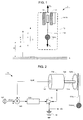
- a mechatronic electrical power generation device 1 comprises a housing 10 which encloses an electromagnetic actuator 11-12, a mobile solid part 13 and an electric circuit 14-16.
- the main components of the electrical circuit are an electronic control 14 controlling the actuator, a reversible amplifier-inverter 15 and a miniature electrical energy storage device 16 such as an accumulator or a super-capacitor.
- Actuator 11-12 is reversible. Under the control of the servocontrol 14, the actuator operates as an electric motor when it is powered by the electrical energy storage device 16 as a voltage source for converting electrical energy into electrical energy. mechanical energy requesting the moving solid part 13, or an electrical generator for converting mechanical energy due to the displacement of the moving solid part into electrical energy to be stored in the storage device which can restore an output voltage VS.
- the actuator is linear synchronous and comprises two main elements: a cylindrical armature with coils 11 fixed inside the housing 10 and a cylindrical inductor with permanent magnets 12 slidable in vertical axial translation in the armature.
- the inductor 12 supports, by a lower end, the mobile solid part 13 via an axial rod 121.
- the relative positions of the armature and the inductor can be reversed.
- the armature is central and fixed to the axial rod 121 and is connected by wiper brushes to the amplifier-inverter 15.
- the inductor is peripheral and surrounds the armature.
- the actuator is a direct current rotating machine comprising a cylindrical stator armature with permanent magnets 11a and a cylindrical rotor coil inductor 12a rotatably mounted in the armature 11a.
- An example of the actuator 11a-12a will be described in more detail with reference to the figures 7 and 8 .
- the solid part 13a in this variant is movable perpendicular to an axial rod 121a of the inductor 12a via a rack 131a whose lower end is fixed to the solid part and which meshes with a wheel toothed 122a attached to one end of the axial shaft 121a.
- the housing 10 is carried by a moving system and undergoes from it accelerations in two opposite directions.
- the moving system is a walker carrying the housing attached to his belt.
- the housing 10 is then subjected to oscillatory displacements substantially in a vertical plane, generated by the walk of the walker and characterized by accelerations in two opposite directions.
- the moving system is a boat subjected to oscillatory movements due to rolling and / or pitching under the effect of the swell.
- the massive part 13 represented in figure 1 is for example all or part of a mobile cellular terminal or a player whose battery is at least in part the electrical energy storage device 16 itself, or any other object such as keychain or wallet.
- the solid part is removable from the actuator through a fixation on the axial stem 121 of the type clips, or woven tapes with hooks and loops, or magnet and iron.
- the housing is returned and the assembly comprising the housing 10, the actuator 11-12 and the electric circuit 14-16 is suspended by the axial rod 121 of the actuator to the belt of the walker so that the part massive consists of at least relatively heavy components of the mechatronic device. An additional mass is then useless.
- an accelerometer is attached to the axial rod of the actuator. The speed of the actuator relative to the axial rod is measured as specified below.
- a mobile cellular terminal or any other object can also be suspended from the housing to make it heavier, as before.
- the arrow pointing upwards materializes the holding force F B exerted by the belt on the housing 10.
- the arrow pointing downwards materializes the action F A of the solid part exerted on the axial rod 121 of the actuator.
- the position of the casing 10 with respect to a reference linked to the ground S and whose origin O is at a height H of the ground and the amplitude of the movement of the casing are denoted x and X.
- the position of the solid part 13 relative to to a reference linked to the housing and the amplitude of the movement of the solid part in the housing are denoted y and Y.
- the housing with all its components has a mass M and the moving mass part has a mass m.
- the actuator 11-12 is slaved so as to automatically take a lot more energy than with a passive generator according to the prior art.
- the housing 10 is for example accelerated upwards and the x coordinate increases, and the solid portion 13 tends to remain in place due to its inertia and the y coordinate decreases.
- the generator then supplies electrical energy that can be stored in the device 16.
- F AT mg + m d 2 x / dt 2 + m d 2 there / dt 2
- F B mg + M - m d 2 x / dt 2 + m d 2 x / dt 2 + m d 2 there / dt 2
- g being the acceleration of gravity
- the mechanical power supplied to the actuator functioning as a generator depends on the vertical acceleration d 2 x / dt 2 imposed on the housing by the walker and the vertical speed dy / dt of the solid part with respect to the housing. Knowing that the acceleration d 2 x / dt 2 imposed on the housing depends on the walker, the invention enslaves the speed dy / dt of the solid part on the acceleration of the housing.
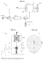
- the electronic servocontrol 14 comprises a speed sensor 141, an accelerometer 142, a subtractor-multiplier 143, a corrector 144 and the reversible amplifier-inverter 15, as shown in FIG. figure 2 .
- the speed sensor 141 measures the speed of rotation of the inductor 12a, or the translational speed of the inductor 12 integrated in the solid part 13a or 13 and therefore captures a quantity proportional to the vertical speed dy / dt of the part massive.
- the speed sensor senses the speed of movement of the inductor as a function of the voltage induced in a winding thereof or the voltage at the terminals of the Hall effect actuator, or by an electro-optical cell.
- the accelerometer 142 is attached to the housing 10 and measures the substantially vertical acceleration d 2 x / dt 2 of the housing.
- the subtractor-multiplier 143 produces a parameter dependent on the measured acceleration of the housing and the measured displacement speed of the solid part.
- the subtractor-multiplier obtains this parameter by multiplying the measured acceleration by a predetermined factor depending in particular on the amplitudes of the acceleration and the speed and subtracts the product obtained to the magnitude proportional to the measured vertical speed dy / dt.
- the corrector 144 corrects the difference delivered by the subtractor-multiplier with respect to a setpoint value dependent on the housing position to apply an input voltage to the inverter-amplifier 15 according to the corrected difference.
- the amplifier-inverter is reversible to adapt the variations of the electrical energy sometimes to recover from the actuator and sometimes to supply the actuator with the DC current and voltage at the terminals. of the storage device 16.
- the amplifier-inverter is connected to the energy storage device 16 and to the actuator 11-12 to impose a current and a voltage on the actuator so that it operates as an electric motor with the electrical energy storage device 16 used as a voltage source, or else an electrical generator for providing the electrical energy load of the storage device 16.
- the solid portion 13a or 13 is lowered to the bottom of the housing, and is raised in the middle of the race of the rack 131a, or the axial rod 121, when the accelerometer detects a movement of the housing.
- the solid portion is permanently balanced by a compression spring fixed between the lower part of the housing and the rack 131a, or the axial rod 121, or by an attraction spring fixed between the upper part of the housing and the rack 131a, or the axial rod 121.
- the parameters f and X are deductible from the measured acceleration d 2 x / dt 2 of the housing.
- the 2Y deflection of the massive part is limited while noting that the greater the deflection, the greater the power to recover.
- the position x of the housing relative to the ground S is imposed by the movements of the walker.
- the position y of the solid part in the housing and its acceleration d 2 y / dt 2 follow from it.
- the speed dx / dt of the housing is maximum and although low, the acceleration d 2 y / dt 2 of the solid part is then maximum, the same sign that the speed of the housing: the device 1 benefit and a significant force F B and therefore a significant power P B at the belt.
- the energy taken is not instantly transmitted to the axial rod 121, 121a of the actuator: a part of the energy taken is first converted into kinetic energy.
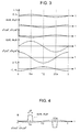
- the slaving of the speed of displacement of the solid part to the acceleration of the housing has a cycle having four phases of operation of the electromagnetic actuator 11-12 which correspond substantially to four quarters of a period and which have some durations unequal since the average power ⁇ P A > is not zero and depends on the product sin (2 ⁇ ft) cos (2 ⁇ ft + ⁇ ) during a period.
- the actuator At the beginning of a half-period T / 2, the actuator first operates as a motor substantially between moments 0 and T / 4 to go up the solid part 13 with a speed increasing substantially to the middle of its course as the acceleration of the housing oriented downward following the descent, that is to say according to the direction opposite to the rise of the massive part, increases; the electrical energy consumed by the actuator is converted into kinetic energy to reduce the acceleration of the massive part. Then substantially between times T / 4 and T / 2, the actuator operates as an electric generator to decrease more and more the speed of the solid part in the direction of the rise during a decrease in the acceleration of the housing according to the direction the descent so as to recover the kinetic energy converted into electrical energy by braking more and stronger the massive part ending up.
- the solid part goes down and the actuator operates as a motor to increase the speed of the solid part following the descent, during an increase of the acceleration of the housing according to the direction of the rise.
- the actuator operates as a generator to increase the speed of the solid part following the descent, during an increase of the acceleration of the housing according to the direction of the rise.
- the automatic sampling of energy is carried out by setting in motion the mechatronic device, without mechanical contact with a fixed reference such as the ground. This justifies the use of inertia since a massive moving portion in a housing tends to remain stationary relative to the ground when the housing is for example suspended from the belt of a walker. The relative movement of the solid part relative to the housing makes it possible to control the actuator provided that energy is sufficiently drawn.
- the recovered energy is maximized by imposing on the axis of the actuator a speed in direct relationship with the acceleration of the housing. Thanks to the enslavement, these two quantities are kept in phase.
- the variation imposed on the speed of the solid part by the servocontrol can be substantially sinusoidal, as in the previous example, or substantially trapezoidal, or of the same type as the acceleration of the housing.
- the amplitude of the speed is determined so as to control the deflection 2Y of the solid part in the housing. If the force F A is limited at the level of the axis of the actuator, the force F B is also, by reaction, limited at the fixing of the housing to the belt. If the speed of the housing is low, then the mechanical power transmitted to the housing by its fixing is very small. In other words, to increase the mechanical power taken by the housing, and therefore the electrical power taken, the invention recommends accelerating and then braking the massive part without artifice, such as the spring suspension of a massive part, to recover electrical energy.
- a large deflection 2Y of the massive part promotes the recovery of energy, in particular from slow movements of the housing.
- a light massive part to be carried by the walker is compatible with a high energy taken up by imposing strong accelerations to the massive part, which results in a large deflection 2Y, which is to adapt to the dimensions of the housing.
- the vertical displacement of the solid portion in the housing may be other than sinusoidal.
- the invention recommends taking advantage of the maximum acceleration of the housing substantially at times T / 4 and 3T / 2 of a period T so that the actuator 11-12 operates as a motor and prints a very high speed at the solid portion 13, since the average power ⁇ P A > supplied to the actuator is proportional to the product of the acceleration d 2 x / dt 2 of the housing and the speed dy / dt of the massive part which is enslaved on the acceleration.
- the solid part is then braked by the actuator operating in electric generator when the acceleration of the housing is lower substantially around times 0 and T / 2.
- the figure 4 illustrates such an optimization with a speed dy / dt of the massive part increasing abruptly around the instants T / 4 and 3T / 2 of a period T, according to a substantially trapezoidal variation during a period ⁇ T shorter than the period T.
- the optimization is obtained by the servocontrol 14 which imposes, through the corrector 144, current setpoints generating "pulses" of moving mass part velocity always of the same amplitude Y and of the same duration ⁇ T corresponding to the maximum deflection of the solid part and synchronized with maximum acceleration of the housing.
- the actuator 11-12 has a two-phase operating cycle corresponding to two half-periods.
- the actuator runs suddenly in motor just at the beginning of the speed pulses of duration ⁇ T substantially between the instants (T / 4- ⁇ T / 2) and T / 4 and between (3T / 4- ⁇ T / 2) and 3T / 4 for suddenly increase the speed of movement of the solid part following the rise and the fall to its maximum during an increase in absolute value of the acceleration of the case.
- the recoverable power and of the order of P 0.605 W if the optimization with peaks of speed of the mobile bulk part is implemented according to the figure 4 .
- the optimization allows to gain a factor of 4 / ⁇ compared to the realization with a simple speed control.
- the speed dy / dt of the solid part can increase and decrease around instants T / 4 and 3T / 2 asymmetrically.
- the first embodiment of the invention described above with its variants is sufficient to supply with an output voltage VS a small electrical object, for example as a mobile cellular terminal, a cardio tachometer, or a GPS location device carried by an animal.
- a small electrical object for example as a mobile cellular terminal, a cardio tachometer, or a GPS location device carried by an animal.
- a switch can be provided at the output thereof so as not to power the actuator 11-12 and the control 14 as the accelerometer 142 does not detect any displacement of the housing during a predetermined period.
- a clock is included in the mechatronic device 1 and serves for the expiry of each predetermined period to wake the mechatronic device 1 so that the speed sensor 141 possibly detects a displacement of the solid part, or so that the accelerometer 142 optionally detects movement of the housing.
- the servocontrol 14 no longer controls the actuator 11-12 motor during the parts of the operating cycle of the actuator which are substantially between times 0 and T / 4 and substantially between times T / 2 and 3T / 4 with reference to figure 3 . During these parts of the cycle, the massive part 12-13 moves freely.
- the servocontrol 14 only serves to control the generator actuator to charge the electrical energy storage device 16 during the other parts of the cycle. operation of the actuator substantially between the times T / 4 and T / 2 and substantially between times 3T / 4 and T.
- the above explanations are also valid if one considers a natural oscillatory movement in another direction, for example pitching or rolling for a boat.
- the solid part is then subjected to the natural oscillation, but the effect of its weight can go as far as being canceled out horizontally, for example, which eliminates the need for balancing at rest.
- the mounting of the device may be of the pendulum type.
- a mechatronic device for generating electrical energy 2 comprises a housing and a solid part 23 which can be driven by rotational movements, instead of the linear movements of the housing 10 and the massive part. 13 according to the first embodiment of the invention.
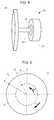
- the solid part 23 may comprise a flywheel which is fixed at one end of an axial rod 221 of a rotor inductor 22 adapted to rotate in a stator armature 21 of a reversible rotary actuator 21-22.
- the flywheel is replaced by two flyweights which are fixed or can slide freely symmetrically on a diametral rod fixed at one end of the axial rod 221, or which can slide symmetrically on the diametral rod in a controlled manner via the 24, or which are mounted at the ends of two opposite peaks of a deformable quadrilateral of which another vertex is fixed at the end of the axial rod and whose deformation can be controlled by means of the servocontrol 24.
- the variants with movable flyweights on the diametral rod or with the deformable quadrilateral make it possible to adjust the moment of inertia of the solid part as a function of the enslaved phases of the operating cycle of the actuator.
- a piston system can also move an incompressible fluid to adjust the moment of inertia of the solid portion relative to the axis of rotation.
- the deflection 2 ⁇ Y of the solid part 23 is now angular and is no longer limited by the vertical dimension of the housing.
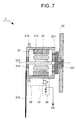
- the figure 7 shows in greater detail the second embodiment of the mechatronic device according to the invention which includes a reversible electromagnetic actuator rotating for example four poles in the form of a magnet synchronous rotating machine more conventional than a linear actuator.
- the mechatronic device 2 comprises a housing 20 containing the actuator 21-22, the moving solid part consisting essentially of the cylindrical rotor inductor 22 of the actuator, and an electric circuit 24-26. If the inertia of the rotor inductor is insufficient, the solid part may be completed by a small flywheel integral with the axial rod 221 of the rotor inductor, such as the flywheel 23 shown in FIG. figure 5 .
- the housing 20 is shown partially in the form of a vertical support which is for example fixed under the belt or the leg of a walker.
- the housing 20 is rotatably mounted via a ball bearing 201 around a pivot 211 fixed to one end of a mild steel cylinder 212.
- a cylindrical stator armature 21 of the actuator is fixed on the surface internal cylinder 212 whose ends are closed and rotatably mounted around the axial rod 221 of the rotor inductor 22 by means of two ball bearings 213.
- the outer surface of the cylinder 212 supports the control 24, the reversible amplifier-inverter 25 and the miniature electrical energy storage device 26.
- the stator armature 21 is driven by a relatively slow rotational movement with respect to the rapid rotational movement of the rotor inductor 22.
- One end of the cylindrical armature 21 supports the pivot 211 decoupled in rotation from the housing 20 by the ball bearing 201.
- the ball bearings 213 decoupling in rotation the rotor armature 22.
- the relative positions of the armature and the inductor can be reversed.
- the armature is central and fixed to the axial rod 221 and is connected by brushes to the amplifier-inverter 25.
- the inductor is peripheral and fixed to the inner surface of the cylinder 212.
- the flywheel is replaced by the masses of certain components of the mechatronic device, such as some relatively heavy components of the electrical circuit 24-26 as the storage device 26, and / or by a mobile cellular terminal when it is to be supplied with an output voltage VS by the storage device 26.
- These additional masses are fixed to the axial rod 221 a, 221 b of the actuator 21a-22a, 21b-22b to take advantage of the overall inertia.
- a coupling arm 214 adapted to be driven by a slow oscillatory movement due to the walker.
- An angular acceleration measurement sensor attached to the cylinder 212 of the stator armature 21 is composed of two miniature accelerometers 215 diametrically opposed with respect to the axial rod 221.
- the accelerometers 215 are capable of measuring opposite accelerations in a direction of sensitivity. acceleration measurement substantially parallel to the ground when the housing is hooked to the leg of the walker.
- the electronic servocontrol 24 shown in FIG. figure 8 to control the actuator 21-22 is similar to the servocontrol 14 according to the first embodiment.
- the electronic servocontrol 24 comprises a speed sensor 241 measuring the angular rotation speed of the inductor 21 and the dual accelerometer sensor 242 which are connected to the differential inputs of a control circuit 243-244-25, in a manner similar to the first embodiment shown in FIG. figure 2 .
- a corrector 244 in the control circuit collects a subtractor-multiplier 243 a difference between on the one hand the product of the angular acceleration measured by a predetermined factor depending in particular on the amplitudes of the angular acceleration and the angular velocity and on the other hand a magnitude proportional to the angular velocity d ⁇ y / dt and compares the obtained difference to a setpoint value dependent on the angular position ⁇ x of the housing.
- the result of the comparison serves to apply an input voltage to the amplifier-inverter 25 connected to the energy storage device 26 to impose a current and a voltage on the actuator 21-22 for the latter to operate.
- the mechatronic device 2 can be worn on the wrist or the thigh of a walker, or fixed on a boat.
- the power supply of the electrical circuit 24-26 can be manually cut off by a switch so as not to supply the power supply.
- actuator 21-22 and the servo 24 as the sensor with two accelerometers 242 detects no movement of the housing for a predetermined period.
- the operating principle of the mechatronic device 2 is essentially similar to that of the mechatronic device 1 according to the first embodiment, by matching a linear speed to an angular rotation speed and a linear acceleration to an angular rotation acceleration. Thanks to the mechanical decoupling of the housing 20 with respect to the stator armature 21 conferred by at least the ball bearing 201, the stator armature is driven by natural movements of the moving system, such as a walker, on which an energy mechanical must be recovered.
- the movement of the system has a rotational component as is the case around the thigh neck of a walker's thigh, or at the wrist of the latter, or on a boat undergoing roll and / or pitch.
- the energy recovered by the natural oscillation of the stator armature 21 is maximized by imposing on the rotating solid part constituted by the rotor inductor 22 an angular velocity directly related to the angular acceleration of the stator armature.
- the own angular velocity of the rotor inductor 22 is no longer limited by dimensional constraints of the housing 20 and can be very high. compared to the low angular velocity of the stator armature 21, a maximum of energy is to be recovered.
- the arrow oriented in the trigonometric direction materializes a resistant torque C B exerted by the body of the walker on the stator armature.
- the arrow oriented in the inverse trigonometric direction materializes the action C A of the flywheel 23 and the rotor inductor 22 exerted on the axial rod 221 of the actuator.
- the angular position of the stator armature 21 for example with respect to a vertical V linked to the ground and the angular amplitude of the rotational movement of the stator armature are denoted ⁇ x and ⁇ X.
- the angular position of the solid part relative to a reference point linked to a radius R of the stator armature and the amplitude of the rotational movement of the solid part in the housing are denoted ⁇ y and ⁇ Y.
- the device 2 with the housing and all its components has an overall moment of inertia J and the total moving mass portion 22-23 comprising in particular the rotor armature 22, the axial rod 221 and possibly the flywheel 23 has a moment of inertia j.
- These powers have the same average value P neglecting any friction in the housing and assuming that all the rotations are periodic, which requires that all derivative products depending on the same variable ⁇ x or ⁇ y are zero on average.
- the first previous relation expresses that the mechanical power supplied to the actuator functioning as a generator depends on the angular acceleration d 2 ⁇ x / dt 2 imposed on the stator armature by the walker and the angular velocity d ⁇ y / dt of the solid part with respect to the stator armature. Knowing that the acceleration d 2 ⁇ x / dt 2 imposed on the stator armature depends on the walker, the invention enslaves the speed d ⁇ y / dt of the solid part on the acceleration of the stator armature.
- the angular position ⁇ x of the stator armature with respect to the vertical V is imposed by the movements of the walker.
- the angular position ⁇ y of the solid part in the housing and its acceleration d 2 ⁇ y / dt 2 derive therefrom.
- the angular velocity d ⁇ x / dt of the stator armature is maximum and although low, the angular acceleration d 2 ⁇ y / dt 2 of the solid part is then maximal, of the same sign as the speed of the stator armature: the device 2 thus benefits from a large torque C B and therefore a significant power P B at the leg.
- the energy taken is not instantaneously transmitted to the axial rod 221 of the actuator: a part of the energy taken is first converted into kinetic energy.
- the actuator 21-22 operates as a motor substantially between the instants 0 and T / 4 in order to turn the solid part 22-23 along the trigonometric direction with an increasing angular velocity substantially until to the radius R as long as the angular acceleration of the stator armature increases according to the inverse trigonometric direction; the electrical energy consumed by the actuator is converted into kinetic energy to reduce the acceleration of the massive part.
- the actuator operates as an electrical generator so as to recover the kinetic energy by braking the solid part whose angular velocity in the trigonometric direction decreases while the angular acceleration of the stator armature decreases according to the inverse trigonometrical direction.
- the solid part rotates in the opposite trigonometric direction, and there is an increase in the angular velocity of the solid part by the actuator operating in motor during an increase of the angular acceleration in the trigonometric direction, then a decrease in the angular velocity of the solid part by braking exerted by the actuator during a decrease in the angular acceleration of the next stator armature in the trigonometric direction.
- the actuator 21-22 operates in both directions of rotation: the actuator on the one hand accelerates its movement and therefore consumes electrical energy and on the other hand recovers energy electrical and therefore brakes his movement.
- the movement of the actuator is synchronized with that of the walker so that the latter feels a resistance, a guarantee of a certain mechanical energy recovered from the movements of the walker, converted by the actuator and transmitted to the storage device.
- electrical energy 26 via the electric circuit. This energy is not transmitted instantaneously to the storage device because the solid portion 22-23 transiently stores energy.
- the equations of the movements and their resolution as described above show that the electrical energy, or the mechanical energy at the actuator, oscillates between two extreme values which can be much higher in absolute value than its mean value, the latter ensuring the recharging of the storage device.
- the actuator 21-22 accelerates and brakes violently the massive part 22-23 because the movements of the walker are relatively long, that is to say the rotation of the leg at the hip at a slow angular speed and because it is necessary for the walker to feel a significant effort to obtain sufficient power.
- a variant of the operation of the actuator according to the invention consists of rotating the solid part 22-23 at a high nominal angular speed, in practice much higher than the maximum angular speed of the stator armature, and making vary the angular velocity d ⁇ y / dt of the solid part around this nominal angular velocity.
- This variant has the advantage of operating the electric circuit 24-26 with a high average voltage greater than that of the storage device 26 for example, and to have permanently a strong inertial coupling between the solid part and the walker.
- the servo may be such that the maximum angular velocity of the solid part is reached in several steps of the walker, instead of a single step.
- the displacement of the solid portion 22-23 in the housing 20 may be other than sinusoidal.
- the invention recommends taking advantage of the maximum of the acceleration of the stator armature substantially at times T / 4 and 3T / 4 of a period T for the actuator to operate as a motor and to print abruptly a very high speed to the solid part, since the average power ⁇ P A > supplied to the actuator 21-22 is proportional to the product of the acceleration d 2 ⁇ x / dt 2 of the stator armature and the speed d ⁇ y / dt of the massive part which is enslaved on the acceleration.
- the solid part is then braked by the actuator operating as an electric generator when the acceleration of the stator armature decreases in absolute value.
- the time interval ⁇ T is no longer limited in the same way and may possibly reach the half-period T / 2 to take advantage of the lower accelerations of the stator armature.
- the figure 4 also illustrates an example of optimization with an angular velocity d ⁇ y / dt of the massive part increasing abruptly around times T / 4 and 3T / 2 of a period T, according to a substantially trapezoidal variation with a symmetrical increase and decrease during a duration ⁇ T shorter than the period T.
- the optimization is obtained by the servocontrol 24 which imposes, through the corrector 244, current setpoints generating "pulses" of moving mass part velocity always of the same amplitude Y and of the same duration ⁇ T corresponding to the maximum displacement of the solid part and synchronized with a maximum acceleration of the stator armature.
- the maximum recoverable power is 3 W if the speed of the massive part is slaved to the acceleration of the stator armature of sinusoidal form.
- the angular rotation speed of the mobile bulk part is limited to a maximum (d ⁇ y / dt) max since the amplitude ⁇ Y of the solid portion 22-23 is no longer limited by the dimensions of the housing 20.
- the optimization thus makes it possible to gain a factor of 4 / ⁇ compared to the realization with a simple speed control.
- the variation of the angular velocity of the solid part is asymmetrical around times T / 4 and 3T / 2.
- the servocontrol may be such that the operating cycle of the rotary actuator extends over several steps of the walker, in particular asymmetrically with a number of steps to reach a maximum angular speed of the massive part. different from a number of steps to reach a minimum angular velocity of the massive part.
- the solid part 23 of mass m is in the form of a rotating disk of radius r.
- a variation of the angular velocity causes a variation of energy by interaction with the motor movement of the slow stator armature to capture the energy and an opposite variation to restore it to the storage device 26:
- the energy recovered is even higher than the angular velocity of the solid part is high.
- a variant of the operation of the actuator according to the invention then consists of rotating the solid portion 22-23 at a high nominal angular velocity and varying the angular velocity d ⁇ y / dt of the solid portion around this angular velocity nominal.
- This variant has the advantage of operating the electric circuit 24-26 with a high average voltage greater than that of the storage device 26 for example, and to have permanently a strong inertial coupling between the solid part and the actuator.
- the power limits to be taken are also dependent on the comfort of the user-walker. It is not necessary that the reaction force is too strong and punctual on the leg, or that there is a gyroscopic force too important to overcome.
- two mechatronic devices according to the invention are positioned symmetrically on the sides of the body. The recoverable power is then of the order of Watt, which becomes sufficient to recharge at least partially a mobile cellular terminal.
- the servo-control 24 no longer controls the actuator 21-22 while driving. parts of the operating cycle of the actuator which are substantially between times 0 and T / 4 and substantially between times T / 2 and 3T / 4 with reference to figure 3 . During these parts of the cycle, the massive part 22-23 moves freely.
- the servocontrol 24 serves only to control the generator actuator to charge the storage device 26 during the other parts of the operating cycle of the actuator substantially between the instants T / 4 and T / 2 and substantially between the moments 3T / 4 and T.
- an elastic means such as a spring is introduced between the housing and the solid part to assist the actuator particularly to accelerate the solid part when the actuator operates as a motor.
- a compression coil spring 17 has ends connected to the bottom 101 of the housing 10 and to the solid part 13.
- the massive part is to accelerate more or less violently upward, as has been demonstrated in the quarter of period 0 to T / 4 in the figure 3 .
- the spring 17 which is compressed when the solid part is downward expands to push the solid part up against the gravity until the solid part reaches a maximum speed before being braked.
- another compression coil spring has ends connected to the upper part of the casing 10 and to the solid part 13.
- the elastic means comprises a spiral spring 27 whose peripheral end 271 is fixed to the housing 20 and whose central end 272 is fixed around the axial rod 221 of the rotor inductor 22, as shown in FIG. figure 10 .
- a reduction is introduced between the spring and the actuator.
- a stiffness adjusting means with radial slider 273 on the last turn makes it possible to adjust more or less the stiffness of the spring 27 according to the walker.
- the spring significantly reduces the weight and bulk of the actuator provided that the frequency of the movements imposed on the stator armature does not deviate too much from the own oscillation frequency of the massive part assembly and spring.
- a spring stiffness adjusting means such as slider 273 is used to match these frequencies as much as possible.
- the spiral spring is completed by a spiral spring mounted in opposition of torsion around the axial rod 221, or is replaced by a helical compression spring or two axial torsion compression springs opposite opposite mounted around one end of the axial rod 221.
- the enslavement can then also relate to the stiffness of the elastic means such as one or two springs.
Landscapes
- Engineering & Computer Science (AREA)
- Power Engineering (AREA)
- Connection Of Motors, Electrical Generators, Mechanical Devices, And The Like (AREA)
- General Electrical Machinery Utilizing Piezoelectricity, Electrostriction Or Magnetostriction (AREA)
- Rehabilitation Tools (AREA)
- Charge And Discharge Circuits For Batteries Or The Like (AREA)
Claims (13)
- Verfahren zur Erzeugung von elektrischer Energie mit Hilfe eines Aktuators (11-12, 21-22), der elektrisch an ein Mittel zur Speicherung von elektrischer Energie (16, 26) angeschlossen ist, und umfassend ein erstes Element (11, 21), das geeignet ist, einer Bewegung mit Schwingungsgeschwindigkeit unterzogen zu werden, und ein zweites Element (12, 22), das zumindest teilweise ein massives Teil (13, 23) darstellt, das geeignet ist, in Bezug zum ersten Element in Geschwindigkeit zu schwingen, dadurch gekennzeichnet, dass es eine Steuerung der Bewegung des massiven Teils bei der Schwingungsbewegung des ersten Elements umfasst, um den Aktuator als Generator zu steuern, der das Speichermittel während eines Teils eines Funktionszyklus des Aktuators auflädt, wobei sich das massive Teil (13, 23) frei während eines weiteren Teils des Funktionszyklus des Aktuators (11-12, 21-22) bewegt.
- Verfahren zur Erzeugung von elektrischer Energie mit Hilfe eines Aktuators (11-12, 21-22), der elektrisch an ein Mittel zur Speicherung von elektrischer Energie (16, 26) angeschlossen ist, und umfassend ein erstes Element (11, 21), das geeignet ist, einer Bewegung mit Schwingungsgeschwindigkeit unterzogen zu werden, und ein zweites Element (12, 22), das zumindest teilweise ein massives Teil (13, 23) darstellt, das geeignet ist, in Bezug zum ersten Element in Geschwindigkeit zu schwingen, dadurch gekennzeichnet, dass es umfasst:- eine Steuerung der Bewegung des massiven Teils bei der Schwingungsbewegung des ersten Elements, um den Aktuator als Generator zu steuern, der das Speichermittel während eines Teils eines Funktionszyklus des Aktuators auflädt,- eine Steuerung der Bewegung des massiven Teils bei der Schwingungsbewegung des ersten Elements, um den Aktuator als Motor zu steuern, der von dem Speichermittel während eines weiteren Teils des Funktionszyklus des Aktuators (11-12, 21-22) versorgt wird.
- Verfahren nach den Ansprüchen 1 oder 2, bei dem sich die Steuerung, um den Aktuator als Generator zu steuern, auf die Bewegungsgeschwindigkeit des massiven Teils, das bei der Beschleunigung des ersten Elements gesteuert wird, bezieht.
- Verfahren nach Anspruch 2, bei dem der Funktionszyklus des Aktuators (11-12, 21-22) eine Funktionsphase (0-T/4) des Aktuators (11-12, 21-22) als Motor, um die Bewegungsgeschwindigkeit des massiven Teils in eine vorbestimmte Richtung während einer Erhöhung der Beschleunigung des ersten Elements in eine zur vorbestimmten Richtung entgegengesetzte Richtung zu erhöhen, eine Funktionsphase (T/4-T/2) des Aktuators als Generator, um die Bewegungsgeschwindigkeit des massiven Teils in die vorbestimmte Richtung während einer Verringerung der Beschleunigung des ersten Elements in die entgegengesetzte Richtung zu verringern, eine Funktionsphase (T/2-3T/4) des Aktuators als Motor, um die Bewegungsgeschwindigkeit des massiven Teils in die entgegengesetzte Richtung während einer Erhöhung der Beschleunigung des ersten Elements in die vorbestimmte Richtung zu erhöhen, und eine Funktionsphase (3T/4-T) des Aktuators als Generator umfasst, um die Bewegungsgeschwindigkeit des massiven Teils in die entgegengesetzte Richtung während einer Verringerung der Beschleunigung des ersten Elements in die vorbestimmte Richtung zu verringern.
- Verfahren nach Anspruch 2, bei dem der Funktionszyklus des Aktuators (11-12, 21-22) Funktionsphasen (ΔT) des Aktuators als Motor umfasst, um die Bewegungsgeschwindigkeit des massiven Teils zu erhöhen und zu verringern, wenn die Beschleunigung des ersten Elements um ein Maximum variiert.
- Vorrichtung zur Erzeugung von elektrischer Energie, umfassend einen Aktuator (11-12, 21-22), der elektrisch an ein Mittel zur Speicherung von elektrischer Energie (16, 26) angeschlossen ist, und umfassend ein erstes Element (11, 21), das geeignet ist, einer Bewegung mit Schwingungsgeschwindigkeit unterzogen zu werden, und ein zweites Element (12, 22), das zumindest teilweise ein massives Teil (13, 23) darstellt, das geeignet ist, in Bezug zum ersten Element in Geschwindigkeit zu schwingen, dadurch gekennzeichnet, dass sie ein Steuerungsmittel (14, 24) zur Steuerung des Aktuators als Generator, der das Speichermittel auflädt, wobei die Bewegung des massiven Teils während der Schwingungsbewegung des ersten Elements während eines Teils eines Funktionszyklus des Aktuators gesteuert wird, und zur Steuerung des Aktuators (11-12, 21-22) als Motor umfasst, der von dem Speichermittel (16, 26) während eines weiteren Teils des Funktionszyklus des Aktuators versorgt wird.
- Vorrichtung nach Anspruch 6, bei der das Steuerungsmittel (14, 24) ein Mittel (142, 242) zum Messen einer Beschleunigung des ersten Elements (11, 21), ein Mittel (141, 241) zum Messen einer Bewegungsgeschwindigkeit des massiven Teils, und ein Mittel (143, 144, 15, 16; 243, 244, 25, 26) umfasst, das den Aktuator steuert, um die Bewegungsgeschwindigkeit des massiven Teils bei der Beschleunigung des ersten Elements zu steuern.
- Vorrichtung nach Anspruch 7, bei der das Steuerungsmittel ein Mittel (143, 144; 243, 244), um einen Parameter, der von der gemessenen Beschleunigung des ersten Elements und der gemessenen Bewegungsgeschwindigkeit des massiven Teils in Bezug zu einem variablen Sollwert abhängt, der von der Position des ersten Elements abhängt, zu korrigieren, und einen reversiblen Verstärker-Wechselrichter (15, 25) umfasst, um die Variationen der elektrischen Energie, die sowohl vom Aktuator zu gewinnen, als auch an den Aktuator zu liefern ist, mit Gleichstrom und -spannung an den Klemmen des Speichermittels (16, 26) gemäß dem korrigierten Parameter anzupassen.
- Vorrichtung nach Anspruch 6, bei der die Bewegung des massiven Teils (23) rotierend ist, und der Aktuator (21-22) drehend ist.
- Vorrichtung nach Anspruch 9, bei der das Steuerungsmittel geeignet ist, die Bewegungsgeschwindigkeit des massiven Teils (22, 23) um eine höhere Nominalgeschwindigkeit als die maximale Winkelgeschwindigkeit des ersten Elements (21) zu variieren.
- Vorrichtung nach Anspruch 10, umfassend ein Mittel (201), um ein Gehäuse (20), das den Aktuator (21-22) des ersten Elements (21) trägt, in Drehung zu entkoppeln.
- Vorrichtung nach Anspruch 6, umfassend ein elastisches Mittel (17, 27), das an einem Gehäuse (10, 20), das den Aktuator (11-12, 21-22) trägt, befestigt ist, um den Aktuator bei der Beschleunigung des massiven Teils (13, 23) zu unterstützen, wenn der Aktuator als Motor funktioniert.
- Vorrichtung nach Anspruch 6, bei der das bewegliche massive Teil (13, 23) auf abnehmbare Weise mindestens einen Teil eines mobilen Endgeräts umfasst, das mit dem Speichermittel (16, 26) verbunden ist.
Applications Claiming Priority (2)
| Application Number | Priority Date | Filing Date | Title |
|---|---|---|---|
| FR0852697 | 2008-04-22 | ||
| PCT/FR2009/050722 WO2009138645A2 (fr) | 2008-04-22 | 2009-04-17 | Dispositif mecatronique portable de generation d'energie electrique |
Publications (2)
| Publication Number | Publication Date |
|---|---|
| EP2308167A2 EP2308167A2 (de) | 2011-04-13 |
| EP2308167B1 true EP2308167B1 (de) | 2016-11-09 |
Family
ID=40039723
Family Applications (1)
| Application Number | Title | Priority Date | Filing Date |
|---|---|---|---|
| EP09745964.8A Active EP2308167B1 (de) | 2008-04-22 | 2009-04-17 | Tragbare mechatronische anordnung zur erzeugung von elektrischem strom |
Country Status (5)
| Country | Link |
|---|---|
| US (1) | US8823188B2 (de) |
| EP (1) | EP2308167B1 (de) |
| JP (1) | JP5106678B2 (de) |
| CN (1) | CN102037639B (de) |
| WO (1) | WO2009138645A2 (de) |
Families Citing this family (8)
| Publication number | Priority date | Publication date | Assignee | Title |
|---|---|---|---|---|
| CN101867216B (zh) * | 2010-05-12 | 2014-06-11 | 中兴通讯股份有限公司 | 一种移动终端充电装置及移动终端 |
| TW201207585A (en) * | 2010-08-05 | 2012-02-16 | Chi Mei Comm Systems Inc | Mobile electronic device rocking system and method thereof |
| FR2993725B1 (fr) * | 2012-07-18 | 2015-03-13 | Sasha Madar | Dispositif d'augmentation d'autonomie |
| US10099780B2 (en) * | 2013-10-07 | 2018-10-16 | Sikorsky Aircraft Corporation | Active vibration control actuator |
| PL225484B1 (pl) * | 2014-11-12 | 2017-04-28 | Politechnika Łódzka | Tekstylna ładowarka do zasilania mobilnych urządzeń elektronicznych |
| US10355516B2 (en) * | 2017-04-06 | 2019-07-16 | Sony Corporation | Self-chargeable portable electronic device with a compact power generating circuitry for charging a rechargeable battery |
| GB201719483D0 (en) * | 2017-11-23 | 2018-01-10 | Deciwatt Ltd | Portable apparatus for generating electricity |
| CN110859019B (zh) * | 2018-08-22 | 2021-08-24 | 中国科学院物理研究所 | 波荡器及包括其的激光等离子体x射线源 |
Family Cites Families (20)
| Publication number | Priority date | Publication date | Assignee | Title |
|---|---|---|---|---|
| FR1576528A (de) * | 1968-05-17 | 1969-08-01 | ||
| GB1316950A (en) * | 1969-06-30 | 1973-05-16 | Univ North Wales | Electric generator |
| US3778697A (en) * | 1971-04-26 | 1973-12-11 | Arkon Scient Labor | Solenoid actuators and generators and method of using same |
| JPS6047828B2 (ja) * | 1976-08-11 | 1985-10-23 | セイコーインスツルメンツ株式会社 | 携帯用発電装置 |
| JPH0516879Y2 (de) * | 1986-01-31 | 1993-05-06 | ||
| JP2502127B2 (ja) * | 1988-06-30 | 1996-05-29 | 澤藤電機株式会社 | 発電装置出力制御方式 |
| EP0459062B1 (de) * | 1990-05-28 | 1993-09-22 | Caterpillar Paving Products Inc. | Einrichtung und Verfahren zur Überwachung einer Schwingungsvorrichtung |
| US5347186A (en) * | 1992-05-26 | 1994-09-13 | Mcq Associates, Inc. | Linear motion electric power generator |
| US20040222708A1 (en) * | 1998-11-13 | 2004-11-11 | Barry Reginald Hobson | Electric oscillatory machine |
| US6242823B1 (en) * | 1999-02-05 | 2001-06-05 | Wayne Griswold | Linear electric machine |
| JP3791402B2 (ja) | 2001-01-26 | 2006-06-28 | 松下電工株式会社 | リニア振動モータの駆動制御方法及び駆動制御装置 |
| US6515375B1 (en) * | 2001-07-25 | 2003-02-04 | The United States Of America As Represented By The Secretary Of The Navy | Adaptive wave motion electrical power generator |
| JP2003079063A (ja) * | 2001-08-31 | 2003-03-14 | Sony Corp | 電子装置 |
| US7288860B2 (en) * | 2002-02-19 | 2007-10-30 | Teledyne Licensing, Inc. | Magnetic transducer with ferrofluid end bearings |
| JP2004084683A (ja) * | 2002-08-22 | 2004-03-18 | Sony Corp | アクチュエータ及びアクチュエータを用いた画像検査装置 |
| WO2004049547A1 (ja) * | 2002-11-26 | 2004-06-10 | Matsushita Electric Works, Ltd. | アクチュエータ |
| JP4013152B2 (ja) * | 2003-04-21 | 2007-11-28 | 宏三 大塩 | 運動量変換バンド |
| JP2010532150A (ja) * | 2007-06-29 | 2010-09-30 | スティヒティング・イメック・ネーデルラント | 移動永久磁石ベースの電磁エネルギースカベンジャ |
| FR2930690A1 (fr) * | 2008-04-29 | 2009-10-30 | Julien Gillonnier | Machine electrique a bobine spiralee fixe ou mobile sans fer |
| US20100194117A1 (en) * | 2009-02-05 | 2010-08-05 | Schlumberger Technology Corporation | Electromagnetic device having compact flux paths for harvesting energy from vibrations |
-
2009
- 2009-04-17 EP EP09745964.8A patent/EP2308167B1/de active Active
- 2009-04-17 JP JP2011505571A patent/JP5106678B2/ja active Active
- 2009-04-17 WO PCT/FR2009/050722 patent/WO2009138645A2/fr not_active Ceased
- 2009-04-17 US US12/988,850 patent/US8823188B2/en active Active
- 2009-04-17 CN CN2009801192561A patent/CN102037639B/zh active Active
Also Published As
| Publication number | Publication date |
|---|---|
| WO2009138645A2 (fr) | 2009-11-19 |
| WO2009138645A3 (fr) | 2010-03-25 |
| CN102037639A (zh) | 2011-04-27 |
| CN102037639B (zh) | 2013-08-28 |
| US8823188B2 (en) | 2014-09-02 |
| JP5106678B2 (ja) | 2012-12-26 |
| US20110037260A1 (en) | 2011-02-17 |
| JP2011521608A (ja) | 2011-07-21 |
| EP2308167A2 (de) | 2011-04-13 |
Similar Documents
| Publication | Publication Date | Title |
|---|---|---|
| EP2308167A2 (de) | Tragbare mechatronische anordnung zur erzeugung von elektrischem strom | |
| EP1044130A1 (de) | Kreiselstabilisiertes gerät, insbesondere ein zweibeiniger roboter | |
| WO2012110979A1 (fr) | Ensemble fonctionnant a regime variable | |
| EP1521142A1 (de) | Uhr mit einem mechanischen Uhrwerk, das mit einem elektronischen Regulator gekoppelt ist | |
| EP3502798A1 (de) | Uhrwerksanordnung, die einen mechanischen oszillator umfasst, der mit einer einstellvorrichtung verbunden ist | |
| FR3036378A1 (fr) | Dispositif motorise avec mouvement alternatif d'organe de locomotion et procede de pilotage associe | |
| EP3299908B1 (de) | Armbanduhr mit automatischem aufzug | |
| EP3502797B1 (de) | Uhrwerksanordnung, die einen mechanischen oszillator umfasst, der mit einer einstellvorrichtung verbunden ist | |
| EP3944027B1 (de) | Tragbares gerät, insbesondere armbanduhr, das mit einer stromquellevorrichtung mit einem elektromechanischen wandler ausgestattet ist | |
| EP3502796B1 (de) | Uhrwerksanordnung, die einen mechanischen oszillator umfasst, der mit einer einstellvorrichtung verbunden ist | |
| EP2232048B1 (de) | Ansteuerverfahren eines selbstgeführten starter-generators mit einem abgekürzten vormagnetisierungsschritt | |
| EP2710257A1 (de) | Turbine mit optimierter effizienz | |
| EP4009119B1 (de) | Uhrwerk, das einen generator und eine schaltung zur regulierung der drehfrequenz dieses generators umfasst | |
| EP3166220A2 (de) | Vorrichtung zur dynamischen begrenzung, und verfahren zur dynamischen begrenzung durch eine solche vorrichtung | |
| EP3322084A1 (de) | Anlasskontrollverfahren eines dreiphasigen kollektorlosen elektrischen synchronmotors | |
| FR3079885A1 (fr) | Equipement pour les reseaux electriques, adaptes au stockage et a la restitution d'energie potentielle de pesanteur | |
| CH713332A2 (fr) | Ensemble horloger comprenant un oscillateur mécanique associé à un dispositif de régulation. | |
| KR20180027012A (ko) | 자중력 발전장치 | |
| EP2688188A1 (de) | Vorrichtung zur erhöhung der batterielebensdauer | |
| EP0336795B1 (de) | Mechanischer Mehrfach-Trägheitssensor | |
| WO1989010484A1 (fr) | Procede et ensembles de propulsion utilisant l'oscillation de lames souples, entrainees en rotation dans un champ de force | |
| CH717674A2 (fr) | Objet portable, notamment montre bracelet, comprenant un dispositif d'alimentation muni d'un convertisseur électromécanique. | |
| EP0887913A2 (de) | Verfahren zur Steuerung eines Mikromotors mit konstanter Drehzahl | |
| CH714483A2 (fr) | Pièce d'horlogerie comprenant un oscillateur mécanique associé à un système de régulation. | |
| WO2016027026A1 (fr) | Installation de production d'énergie électrique par conversion d'énergie houlomotrice |
Legal Events
| Date | Code | Title | Description |
|---|---|---|---|
| PUAI | Public reference made under article 153(3) epc to a published international application that has entered the european phase |
Free format text: ORIGINAL CODE: 0009012 |
|
| 17P | Request for examination filed |
Effective date: 20101123 |
|
| AK | Designated contracting states |
Kind code of ref document: A2 Designated state(s): AT BE BG CH CY CZ DE DK EE ES FI FR GB GR HR HU IE IS IT LI LT LU LV MC MK MT NL NO PL PT RO SE SI SK TR |
|
| DAX | Request for extension of the european patent (deleted) | ||
| RAP1 | Party data changed (applicant data changed or rights of an application transferred) |
Owner name: ORANGE |
|
| REG | Reference to a national code |
Ref country code: DE Ref legal event code: R079 Ref document number: 602009042262 Country of ref document: DE Free format text: PREVIOUS MAIN CLASS: H02P0009000000 Ipc: H02P0009060000 |
|
| GRAP | Despatch of communication of intention to grant a patent |
Free format text: ORIGINAL CODE: EPIDOSNIGR1 |
|
| RIC1 | Information provided on ipc code assigned before grant |
Ipc: H02P 9/00 20060101ALI20160519BHEP Ipc: H02J 7/32 20060101ALI20160519BHEP Ipc: H02K 35/00 20060101ALI20160519BHEP Ipc: H02P 9/06 20060101AFI20160519BHEP |
|
| INTG | Intention to grant announced |
Effective date: 20160610 |
|
| GRAS | Grant fee paid |
Free format text: ORIGINAL CODE: EPIDOSNIGR3 |
|
| GRAA | (expected) grant |
Free format text: ORIGINAL CODE: 0009210 |
|
| AK | Designated contracting states |
Kind code of ref document: B1 Designated state(s): AT BE BG CH CY CZ DE DK EE ES FI FR GB GR HR HU IE IS IT LI LT LU LV MC MK MT NL NO PL PT RO SE SI SK TR |
|
| REG | Reference to a national code |
Ref country code: GB Ref legal event code: FG4D Free format text: NOT ENGLISH |
|
| REG | Reference to a national code |
Ref country code: AT Ref legal event code: REF Ref document number: 844734 Country of ref document: AT Kind code of ref document: T Effective date: 20161115 Ref country code: CH Ref legal event code: EP |
|
| REG | Reference to a national code |
Ref country code: IE Ref legal event code: FG4D Free format text: LANGUAGE OF EP DOCUMENT: FRENCH |
|
| REG | Reference to a national code |
Ref country code: DE Ref legal event code: R096 Ref document number: 602009042262 Country of ref document: DE |
|
| PG25 | Lapsed in a contracting state [announced via postgrant information from national office to epo] |
Ref country code: LV Free format text: LAPSE BECAUSE OF FAILURE TO SUBMIT A TRANSLATION OF THE DESCRIPTION OR TO PAY THE FEE WITHIN THE PRESCRIBED TIME-LIMIT Effective date: 20161109 |
|
| REG | Reference to a national code |
Ref country code: LT Ref legal event code: MG4D |
|
| REG | Reference to a national code |
Ref country code: NL Ref legal event code: MP Effective date: 20161109 |
|
| REG | Reference to a national code |
Ref country code: AT Ref legal event code: MK05 Ref document number: 844734 Country of ref document: AT Kind code of ref document: T Effective date: 20161109 |
|
| REG | Reference to a national code |
Ref country code: FR Ref legal event code: PLFP Year of fee payment: 9 |
|
| PG25 | Lapsed in a contracting state [announced via postgrant information from national office to epo] |
Ref country code: GR Free format text: LAPSE BECAUSE OF FAILURE TO SUBMIT A TRANSLATION OF THE DESCRIPTION OR TO PAY THE FEE WITHIN THE PRESCRIBED TIME-LIMIT Effective date: 20170210 Ref country code: LT Free format text: LAPSE BECAUSE OF FAILURE TO SUBMIT A TRANSLATION OF THE DESCRIPTION OR TO PAY THE FEE WITHIN THE PRESCRIBED TIME-LIMIT Effective date: 20161109 Ref country code: NL Free format text: LAPSE BECAUSE OF FAILURE TO SUBMIT A TRANSLATION OF THE DESCRIPTION OR TO PAY THE FEE WITHIN THE PRESCRIBED TIME-LIMIT Effective date: 20161109 Ref country code: NO Free format text: LAPSE BECAUSE OF FAILURE TO SUBMIT A TRANSLATION OF THE DESCRIPTION OR TO PAY THE FEE WITHIN THE PRESCRIBED TIME-LIMIT Effective date: 20170209 Ref country code: SE Free format text: LAPSE BECAUSE OF FAILURE TO SUBMIT A TRANSLATION OF THE DESCRIPTION OR TO PAY THE FEE WITHIN THE PRESCRIBED TIME-LIMIT Effective date: 20161109 |
|
| PG25 | Lapsed in a contracting state [announced via postgrant information from national office to epo] |
Ref country code: IS Free format text: LAPSE BECAUSE OF FAILURE TO SUBMIT A TRANSLATION OF THE DESCRIPTION OR TO PAY THE FEE WITHIN THE PRESCRIBED TIME-LIMIT Effective date: 20170309 Ref country code: PL Free format text: LAPSE BECAUSE OF FAILURE TO SUBMIT A TRANSLATION OF THE DESCRIPTION OR TO PAY THE FEE WITHIN THE PRESCRIBED TIME-LIMIT Effective date: 20161109 Ref country code: HR Free format text: LAPSE BECAUSE OF FAILURE TO SUBMIT A TRANSLATION OF THE DESCRIPTION OR TO PAY THE FEE WITHIN THE PRESCRIBED TIME-LIMIT Effective date: 20161109 Ref country code: ES Free format text: LAPSE BECAUSE OF FAILURE TO SUBMIT A TRANSLATION OF THE DESCRIPTION OR TO PAY THE FEE WITHIN THE PRESCRIBED TIME-LIMIT Effective date: 20161109 Ref country code: PT Free format text: LAPSE BECAUSE OF FAILURE TO SUBMIT A TRANSLATION OF THE DESCRIPTION OR TO PAY THE FEE WITHIN THE PRESCRIBED TIME-LIMIT Effective date: 20170309 Ref country code: AT Free format text: LAPSE BECAUSE OF FAILURE TO SUBMIT A TRANSLATION OF THE DESCRIPTION OR TO PAY THE FEE WITHIN THE PRESCRIBED TIME-LIMIT Effective date: 20161109 Ref country code: FI Free format text: LAPSE BECAUSE OF FAILURE TO SUBMIT A TRANSLATION OF THE DESCRIPTION OR TO PAY THE FEE WITHIN THE PRESCRIBED TIME-LIMIT Effective date: 20161109 |
|
| PG25 | Lapsed in a contracting state [announced via postgrant information from national office to epo] |
Ref country code: SK Free format text: LAPSE BECAUSE OF FAILURE TO SUBMIT A TRANSLATION OF THE DESCRIPTION OR TO PAY THE FEE WITHIN THE PRESCRIBED TIME-LIMIT Effective date: 20161109 Ref country code: CZ Free format text: LAPSE BECAUSE OF FAILURE TO SUBMIT A TRANSLATION OF THE DESCRIPTION OR TO PAY THE FEE WITHIN THE PRESCRIBED TIME-LIMIT Effective date: 20161109 Ref country code: RO Free format text: LAPSE BECAUSE OF FAILURE TO SUBMIT A TRANSLATION OF THE DESCRIPTION OR TO PAY THE FEE WITHIN THE PRESCRIBED TIME-LIMIT Effective date: 20161109 Ref country code: DK Free format text: LAPSE BECAUSE OF FAILURE TO SUBMIT A TRANSLATION OF THE DESCRIPTION OR TO PAY THE FEE WITHIN THE PRESCRIBED TIME-LIMIT Effective date: 20161109 Ref country code: EE Free format text: LAPSE BECAUSE OF FAILURE TO SUBMIT A TRANSLATION OF THE DESCRIPTION OR TO PAY THE FEE WITHIN THE PRESCRIBED TIME-LIMIT Effective date: 20161109 |
|
| REG | Reference to a national code |
Ref country code: DE Ref legal event code: R097 Ref document number: 602009042262 Country of ref document: DE |
|
| PG25 | Lapsed in a contracting state [announced via postgrant information from national office to epo] |
Ref country code: IT Free format text: LAPSE BECAUSE OF FAILURE TO SUBMIT A TRANSLATION OF THE DESCRIPTION OR TO PAY THE FEE WITHIN THE PRESCRIBED TIME-LIMIT Effective date: 20161109 Ref country code: BG Free format text: LAPSE BECAUSE OF FAILURE TO SUBMIT A TRANSLATION OF THE DESCRIPTION OR TO PAY THE FEE WITHIN THE PRESCRIBED TIME-LIMIT Effective date: 20170209 |
|
| PLBE | No opposition filed within time limit |
Free format text: ORIGINAL CODE: 0009261 |
|
| STAA | Information on the status of an ep patent application or granted ep patent |
Free format text: STATUS: NO OPPOSITION FILED WITHIN TIME LIMIT |
|
| 26N | No opposition filed |
Effective date: 20170810 |
|
| PG25 | Lapsed in a contracting state [announced via postgrant information from national office to epo] |
Ref country code: SI Free format text: LAPSE BECAUSE OF FAILURE TO SUBMIT A TRANSLATION OF THE DESCRIPTION OR TO PAY THE FEE WITHIN THE PRESCRIBED TIME-LIMIT Effective date: 20161109 |
|
| REG | Reference to a national code |
Ref country code: CH Ref legal event code: PL |
|
| REG | Reference to a national code |
Ref country code: IE Ref legal event code: MM4A |
|
| PG25 | Lapsed in a contracting state [announced via postgrant information from national office to epo] |
Ref country code: MC Free format text: LAPSE BECAUSE OF FAILURE TO SUBMIT A TRANSLATION OF THE DESCRIPTION OR TO PAY THE FEE WITHIN THE PRESCRIBED TIME-LIMIT Effective date: 20161109 |
|
| PG25 | Lapsed in a contracting state [announced via postgrant information from national office to epo] |
Ref country code: CH Free format text: LAPSE BECAUSE OF NON-PAYMENT OF DUE FEES Effective date: 20170430 Ref country code: LI Free format text: LAPSE BECAUSE OF NON-PAYMENT OF DUE FEES Effective date: 20170430 Ref country code: LU Free format text: LAPSE BECAUSE OF NON-PAYMENT OF DUE FEES Effective date: 20170417 |
|
| REG | Reference to a national code |
Ref country code: BE Ref legal event code: MM Effective date: 20170430 |
|
| REG | Reference to a national code |
Ref country code: FR Ref legal event code: PLFP Year of fee payment: 10 |
|
| PG25 | Lapsed in a contracting state [announced via postgrant information from national office to epo] |
Ref country code: IE Free format text: LAPSE BECAUSE OF NON-PAYMENT OF DUE FEES Effective date: 20170417 |
|
| PG25 | Lapsed in a contracting state [announced via postgrant information from national office to epo] |
Ref country code: BE Free format text: LAPSE BECAUSE OF NON-PAYMENT OF DUE FEES Effective date: 20170430 |
|
| PG25 | Lapsed in a contracting state [announced via postgrant information from national office to epo] |
Ref country code: MT Free format text: LAPSE BECAUSE OF FAILURE TO SUBMIT A TRANSLATION OF THE DESCRIPTION OR TO PAY THE FEE WITHIN THE PRESCRIBED TIME-LIMIT Effective date: 20161109 |
|
| PG25 | Lapsed in a contracting state [announced via postgrant information from national office to epo] |
Ref country code: HU Free format text: LAPSE BECAUSE OF FAILURE TO SUBMIT A TRANSLATION OF THE DESCRIPTION OR TO PAY THE FEE WITHIN THE PRESCRIBED TIME-LIMIT; INVALID AB INITIO Effective date: 20090417 |
|
| PG25 | Lapsed in a contracting state [announced via postgrant information from national office to epo] |
Ref country code: CY Free format text: LAPSE BECAUSE OF NON-PAYMENT OF DUE FEES Effective date: 20161109 |
|
| PG25 | Lapsed in a contracting state [announced via postgrant information from national office to epo] |
Ref country code: MK Free format text: LAPSE BECAUSE OF FAILURE TO SUBMIT A TRANSLATION OF THE DESCRIPTION OR TO PAY THE FEE WITHIN THE PRESCRIBED TIME-LIMIT Effective date: 20161109 |
|
| PG25 | Lapsed in a contracting state [announced via postgrant information from national office to epo] |
Ref country code: TR Free format text: LAPSE BECAUSE OF FAILURE TO SUBMIT A TRANSLATION OF THE DESCRIPTION OR TO PAY THE FEE WITHIN THE PRESCRIBED TIME-LIMIT Effective date: 20161109 |
|
| PGFP | Annual fee paid to national office [announced via postgrant information from national office to epo] |
Ref country code: DE Payment date: 20250319 Year of fee payment: 17 |
|
| PGFP | Annual fee paid to national office [announced via postgrant information from national office to epo] |
Ref country code: GB Payment date: 20260319 Year of fee payment: 18 |
|
| PGFP | Annual fee paid to national office [announced via postgrant information from national office to epo] |
Ref country code: FR Payment date: 20260320 Year of fee payment: 18 |