EP2309083B1 - Schliesszylinder mit zugehörigem schlüssel und sperrrippenabtastung - Google Patents
Schliesszylinder mit zugehörigem schlüssel und sperrrippenabtastung Download PDFInfo
- Publication number
- EP2309083B1 EP2309083B1 EP10185444.6A EP10185444A EP2309083B1 EP 2309083 B1 EP2309083 B1 EP 2309083B1 EP 10185444 A EP10185444 A EP 10185444A EP 2309083 B1 EP2309083 B1 EP 2309083B1
- Authority
- EP
- European Patent Office
- Prior art keywords
- cylinder core
- key
- pivot lever
- pin
- locking device
- Prior art date
- Legal status (The legal status is an assumption and is not a legal conclusion. Google has not performed a legal analysis and makes no representation as to the accuracy of the status listed.)
- Not-in-force
Links
- 230000000903 blocking effect Effects 0.000 title claims description 25
- 238000001514 detection method Methods 0.000 title 1
- 238000003780 insertion Methods 0.000 claims description 2
- 230000037431 insertion Effects 0.000 claims description 2
- 238000007373 indentation Methods 0.000 claims 4
- 230000004888 barrier function Effects 0.000 description 31
- 210000000481 breast Anatomy 0.000 description 2
- IHQKEDIOMGYHEB-UHFFFAOYSA-M sodium dimethylarsinate Chemical class [Na+].C[As](C)([O-])=O IHQKEDIOMGYHEB-UHFFFAOYSA-M 0.000 description 2
- 238000006073 displacement reaction Methods 0.000 description 1
- 230000013011 mating Effects 0.000 description 1
- 239000002184 metal Substances 0.000 description 1
- 238000000034 method Methods 0.000 description 1
- 230000002093 peripheral effect Effects 0.000 description 1
Images


Classifications
-
- E—FIXED CONSTRUCTIONS
- E05—LOCKS; KEYS; WINDOW OR DOOR FITTINGS; SAFES
- E05B—LOCKS; ACCESSORIES THEREFOR; HANDCUFFS
- E05B27/00—Cylinder locks or other locks with tumbler pins or balls that are set by pushing the key in
- E05B27/0042—Cylinder locks or other locks with tumbler pins or balls that are set by pushing the key in with additional key identifying function, e.g. with use of additional key operated rotor-blocking elements, not of split pin tumbler type
-
- Y—GENERAL TAGGING OF NEW TECHNOLOGICAL DEVELOPMENTS; GENERAL TAGGING OF CROSS-SECTIONAL TECHNOLOGIES SPANNING OVER SEVERAL SECTIONS OF THE IPC; TECHNICAL SUBJECTS COVERED BY FORMER USPC CROSS-REFERENCE ART COLLECTIONS [XRACs] AND DIGESTS
- Y10—TECHNICAL SUBJECTS COVERED BY FORMER USPC
- Y10T—TECHNICAL SUBJECTS COVERED BY FORMER US CLASSIFICATION
- Y10T70/00—Locks
- Y10T70/70—Operating mechanism
- Y10T70/7441—Key
- Y10T70/7486—Single key
- Y10T70/7508—Tumbler type
- Y10T70/7559—Cylinder type
- Y10T70/7565—Plural tumbler sets
-
- Y—GENERAL TAGGING OF NEW TECHNOLOGICAL DEVELOPMENTS; GENERAL TAGGING OF CROSS-SECTIONAL TECHNOLOGIES SPANNING OVER SEVERAL SECTIONS OF THE IPC; TECHNICAL SUBJECTS COVERED BY FORMER USPC CROSS-REFERENCE ART COLLECTIONS [XRACs] AND DIGESTS
- Y10—TECHNICAL SUBJECTS COVERED BY FORMER USPC
- Y10T—TECHNICAL SUBJECTS COVERED BY FORMER US CLASSIFICATION
- Y10T70/00—Locks
- Y10T70/70—Operating mechanism
- Y10T70/7441—Key
- Y10T70/7486—Single key
- Y10T70/7508—Tumbler type
- Y10T70/7559—Cylinder type
- Y10T70/7588—Rotary plug
- Y10T70/7593—Sliding tumblers
- Y10T70/7599—Transverse of plug
- Y10T70/7605—Pin tumblers
-
- Y—GENERAL TAGGING OF NEW TECHNOLOGICAL DEVELOPMENTS; GENERAL TAGGING OF CROSS-SECTIONAL TECHNOLOGIES SPANNING OVER SEVERAL SECTIONS OF THE IPC; TECHNICAL SUBJECTS COVERED BY FORMER USPC CROSS-REFERENCE ART COLLECTIONS [XRACs] AND DIGESTS
- Y10—TECHNICAL SUBJECTS COVERED BY FORMER USPC
- Y10T—TECHNICAL SUBJECTS COVERED BY FORMER US CLASSIFICATION
- Y10T70/00—Locks
- Y10T70/70—Operating mechanism
- Y10T70/7441—Key
- Y10T70/7486—Single key
- Y10T70/7508—Tumbler type
- Y10T70/7559—Cylinder type
- Y10T70/7588—Rotary plug
- Y10T70/7593—Sliding tumblers
- Y10T70/7599—Transverse of plug
- Y10T70/7616—Including sidebar
-
- Y—GENERAL TAGGING OF NEW TECHNOLOGICAL DEVELOPMENTS; GENERAL TAGGING OF CROSS-SECTIONAL TECHNOLOGIES SPANNING OVER SEVERAL SECTIONS OF THE IPC; TECHNICAL SUBJECTS COVERED BY FORMER USPC CROSS-REFERENCE ART COLLECTIONS [XRACs] AND DIGESTS
- Y10—TECHNICAL SUBJECTS COVERED BY FORMER USPC
- Y10T—TECHNICAL SUBJECTS COVERED BY FORMER US CLASSIFICATION
- Y10T70/00—Locks
- Y10T70/70—Operating mechanism
- Y10T70/7441—Key
- Y10T70/7486—Single key
- Y10T70/7508—Tumbler type
- Y10T70/7559—Cylinder type
- Y10T70/7667—Operating elements, parts and adjuncts
- Y10T70/7672—Cylinder
-
- Y—GENERAL TAGGING OF NEW TECHNOLOGICAL DEVELOPMENTS; GENERAL TAGGING OF CROSS-SECTIONAL TECHNOLOGIES SPANNING OVER SEVERAL SECTIONS OF THE IPC; TECHNICAL SUBJECTS COVERED BY FORMER USPC CROSS-REFERENCE ART COLLECTIONS [XRACs] AND DIGESTS
- Y10—TECHNICAL SUBJECTS COVERED BY FORMER USPC
- Y10T—TECHNICAL SUBJECTS COVERED BY FORMER US CLASSIFICATION
- Y10T70/00—Locks
- Y10T70/70—Operating mechanism
- Y10T70/7441—Key
- Y10T70/7486—Single key
- Y10T70/7508—Tumbler type
- Y10T70/7559—Cylinder type
- Y10T70/7667—Operating elements, parts and adjuncts
- Y10T70/7689—Tumblers
- Y10T70/7695—Plate
-
- Y—GENERAL TAGGING OF NEW TECHNOLOGICAL DEVELOPMENTS; GENERAL TAGGING OF CROSS-SECTIONAL TECHNOLOGIES SPANNING OVER SEVERAL SECTIONS OF THE IPC; TECHNICAL SUBJECTS COVERED BY FORMER USPC CROSS-REFERENCE ART COLLECTIONS [XRACs] AND DIGESTS
- Y10—TECHNICAL SUBJECTS COVERED BY FORMER USPC
- Y10T—TECHNICAL SUBJECTS COVERED BY FORMER US CLASSIFICATION
- Y10T70/00—Locks
- Y10T70/70—Operating mechanism
- Y10T70/7441—Key
- Y10T70/7486—Single key
- Y10T70/7508—Tumbler type
- Y10T70/7559—Cylinder type
- Y10T70/7667—Operating elements, parts and adjuncts
- Y10T70/7689—Tumblers
- Y10T70/7701—Pin
Definitions
- the invention relates to a locking device with a lock cylinder and a matching key, wherein the key has a key bit with at least one breast side cut coding recess and extending in the direction of extension of the key bit barrier rib with at least one barrier rib recess, wherein the lock cylinder, a housing with a bearing bore and a in the bearing bore mounted, having a keyway for inserting the key, with not inserted key of at least one mounted in a housing bore housing pin rotationally locked cylinder core, wherein the housing pin projects into a core pin overlapping core bore of the cylinder core and the core pin by entering the coding recess of in the key channel inserted key the housing pin in a rotation of the cylinder core enabling release position can be brought and with a the barrier rib recess scanning locking element which engages a non-existent barrier rib recess rotation of the cylinder core preventing in a locking recess of the bearing bore.
- the EP 0 851 079 A1 describes a lock cylinder with a cylinder core, in the keyway of a flat key can be inserted, which has a locking rib, which can be scanned by a reversing pin.
- the reversing pin disposed in the cylinder core cooperates with a counter pin disposed in the cylinder housing, so that the cylinder core is locked in rotation by this locking device when the fin height is less than or greater than the proper fin height.
- the rib is scanned here on its side wall.
- the WO 2000/022262 describes a lock cylinder and a mating key, with the key bit of the key on one of its two Broad sides has a barrier rib and depressions on the opposite broad side.
- the depressions are scanned by blocking elements. If the recess is missing, the locking elements lock when turning the cylinder core.
- the barrier rib is scanned by a slider. If the barrier rib is missing, the slide can be displaced, so that a capture opening arranged directly next to the core bore is released, into which a housing pin can enter during a partial rotation of the cylinder core, so that the cylinder core can not be turned further.
- the DE 198 38 000 A1 describes a generic locking device with a lock cylinder and a matching key.
- the key has a plurality of coding recesses cut on the breast side, with which core pins mounted in core bores of the cylinder core can be sorted in such a way that the interface between the housing pin and the core pin lies in the lateral surface of the housing bore. Runs transverse to the keyway holes, in each of which locking pins are arranged. These locking pins scan barrier rib recesses of a barrier rib extending in the extension direction of the key bit.
- Such a lock cylinder can be manipulated by filing the barrier rib.
- the invention is based, to increase the manipulation security in a generic lock cylinder the task.
- This pivot lever has a bearing end about which the pivot lever is pivotable. He has a Tastende, which scans the barrier rib in a barrier rib-well-free area.
- the pivot lever closes at the proper barrier rib height a capture opening for the housing pin.
- the capture opening for the housing pin is open, so that the housing pin can be trapped there after a partial rotation of the cylinder core, resulting in a rotation blocking the cylinder core.
- the pivoting lever is not held in a closing position which closes the catching opening.
- the pivot lever is rather offset with its radially outer peripheral edge to the mouth of the capture opening, so that after a partial rotation of the cylinder core of the housing pin can enter into the capture opening.
- the capture opening forms at least one blocking stage, which prevents the cylinder core from further rotation.
- the capture opening according to the invention is circumferentially offset from the core pin hole arranged such that the cylinder core must be rotated by at least 90 ° before the housing pin can enter into the capture opening.
- the pivot lever is preferably designed as a C-shaped metal piece. One end of a C-leg forms the bearing end, the end of the other C-leg forms the scanning end. The pointing away from the C-legs back of the pivot lever forms a bow niche, which preferably has a curved course.
- This arched niche seals the capture opening when the key inserted into the keyway has a proper barrier rib. Missing the proper barrier rib, so the niche is in the direction of the axis of rotation of the cylinder core radially inwardly offset relative to the capture opening, so that forms a catching recess into which the housing pin can enter.
- the course of the edge of the arch niche preferably corresponds to the curvature of the end face of the housing pin.
- the sheet niche is preferably located immediately at the rear of the scanning end, ie away from the end of storage. The latter is preferably in a Lagerernische, of a bearing chamber is formed, in which the pivot lever is mounted. The distance from the bearing end to the scanning end is preferably greater than the radius of the cylinder core.
- a plurality of transverse bores in which locking elements formed by pins can be arranged. Not every transverse hole must be provided with a blocking element.
- the locking elements may be formed by mushroom-like pins. It is considered advantageous that the pivot lever rests without displacement in its storage chamber. This ensures that the scanning end can protrude through an opening in the key channel. According to the development of the invention, the security against manipulation is increased. If the barrier rib filed, so the pivot lever can not be pivoted sufficiently so that the capture opening is not closed by the arcuate niche. If the cylinder core is rotated by more than 90 ° starting from the key withdrawal position, the housing pin is caught in the capture opening so that further rotation and, if necessary, also turning back of the cylinder core is prevented.
- the locking cylinder according to the invention may have a plurality of each disposed at the axial height of a housing bore or core bore bearing chambers.
- the storage chambers can be optionally equipped with swivel levers.
- the bearing chambers, which are not equipped with pivoting levers, can be equipped with filling pieces which permanently close the catching opening.
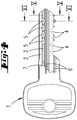
- the in the FIGS. 4 to 6 key shown has a Reide and one of the Reide the key 1 extending key bit 2, which can be inserted into a key channel 12 of a cylinder core 11.
- the key bit 2 has a narrow spine and two substantially parallel key width side surfaces.
- the key bridge opposite the key back is provided with Codéessaussparungen 4, which are notches incisions.
- a barrier rib 3 On a broad side plane of the key bit 2 extends in the extension direction of the key bit 2, that is in the insertion direction of the key 1, a barrier rib 3. This is directly adjacent to the back.
- the barrier rib 3 has a plurality of barrier rib recesses 5, which are formed by blind holes.
- the broad sides of the key bit 2 moreover have a plurality of profile grooves 6 and profile grooves 7, which run parallel to one another and parallel to the barrier rib 3.
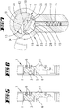
- the lock cylinder 8 has a housing 9, which carries in its center a closing member. This closing member can be coupled with cylinder cores 11, which eino in mutually pioneering bearing bores 10.
- Each of the two lock cylinder halves has arranged in the flange portion of the housing 9 housing bores 16, in each of which a housing pin 15 is located.
- the housing pin 15 is acted upon by a tumbler spring 17, which is supported on the bottom of the housing bore 16, in the direction of the bearing bore 10.
- a cylinder core 11 In the bearing bore 10 is a cylinder core 11 with an axially extending keyway 12 whose cross-sectional profile corresponds to the cross-sectional profile of the key bit 2.
- the cylinder core 11 has a plurality of extending in the radial direction and opening into the keyway 12 core holes 14, in each of which a core pin 13 is arranged.
- the length of the core pins 13 defines the locking secret of the key and corresponds to the coding recesses 4 of the key bit 2.
- the cylinder core 11 has a bearing chamber 23, which is open to the outer circumferential surface of the cylinder core 11.
- the storage chamber 23 forms a recess 24, which forms a bearing niche. This is located at one end of the storage chamber 23.
- the other end of the storage chamber 23 forms an opening 25 to the keyway 12 from.
- the storage chamber 23 supports a C-shaped pivot lever 18.
- the end of a C-leg of the pivot lever 18 forms a bearing end 19 which is mounted in the bearing recess 24 substantially only pivotally and non-displaceably.
- the end of the other C-leg of the pivot lever 18 engages through the opening 25 and forms a scanning end 20 for the barrier rib 3 from.
- the on a curved line, which corresponds to the circumferential contour line of the cylinder core 11, running back of the pivot lever 18 has near the sensing end 20 a bow niche 21 with a slightly arcuate niche ground.
- the bearing chamber 23 is widened in the axial direction such that it forms a capture opening 28 for a housing pin 15.
- the storage chamber 23 is made narrower so that the housing pin 15 can not enter there.
- release position of the pivot lever 18 is held by support on the locking rib 3 in a position in which the capture opening 28 is closed by the niche sheet 21.
- the capture opening 28 is not closed by the back of the pivot lever 18.
- An end portion with a curved end face 15 'of the housing pin 15 can enter into the catching opening 28 in this catching position.
- the housing pin 15 which has entered into the capture opening 28 blocks further rotation of the cylinder core 11.
- the rounding of the arc niche 21 essentially corresponds to the curvature of the end face 15 '.
- At least one of the barrier rib recesses 5 is scanned by a blocking element 26.
- the latter has a diameter-reduced locking end 26 'and an enlarged diameter locking end 26 "
- the blocking element 26 is mounted in a transverse bore 27 to the keyway 12.
- the transverse bore 27 is located approximately at the level of the niche 21. In the key withdrawal position ( Fig. 3 )
- the transverse bore 27 is aligned with a locking recess 22 which may be formed by an axial groove in the wall of the bearing bore 10.
- the cylinder core 11 can be rotated Locking rib 3 is held with its locking end 26 "in the locking recess 22, so that the cylinder core 11 is rotationally locked. If the barrier rib 3 is filed away, as it is in the in Fig. 7 key shown is the case, the locking elements 26 can not develop a blocking function. Because of the pivot lever 18, which is not displaced into the release position, the housing pin 15 is, however, caught in the capture opening 28 after a partial rotation of the cylinder core, which is between 90 ° and 180 °. While trained by pins locking elements 26 are used for depth query of wells, the pivot lever 18 is used for height sensing a barrier rib third
Landscapes
- Lock And Its Accessories (AREA)
- Refuge Islands, Traffic Blockers, Or Guard Fence (AREA)
- Pivots And Pivotal Connections (AREA)
Description
- Die Erfindung betrifft eine Schließvorrichtung mit einem Schließzylinder und einem passenden Schlüssel, wobei der Schlüssel einen Schlüsselbart mit mindestens einer insbesondere brustseitig eingeschnittenen Codierungsaussparung und eine in Erstreckungsrichtung des Schlüsselbartes verlaufende Sperrrippe mit mindestens einer Sperrrippenvertiefung aufweist, wobei der Schließzylinder ein Gehäuse mit einer Lagerbohrung und einen in der Lagerbohrung gelagerten, einen Schlüsselkanal zum Einstecken des Schlüssels aufweisenden, bei nicht eingestecktem Schlüssel von mindestens einem in einer Gehäusebohrung gelagerten Gehäusestift drehgesperrten Zylinderkern aufweist, wobei der Gehäusestift in eine einen Kernstift lagernden Kernbohrung des Zylinderkernes ragt und der Kernstift durch Eintritt in die Codierungsaussparung des in den Schlüsselkanal eingesteckten Schlüssels den Gehäusestift in eine ein Drehen des Zylinderkerns ermöglichende Freigabestellung bringbar ist und mit einem die Sperrrippenvertiefung abtastenden Sperrelement, welches bei nicht vorhandener Sperrrippenvertiefung ein Drehen des Zylinderkernes verhindernd in eine Sperrausnehmung der Lagerbohrung eingreift.
- Die
EP 0 851 079 A1 beschreibt einen Schließzylinder mit einem Zylinderkern, in dessen Schlüsselkanal ein Flachschlüssel eingeschoben werden kann, der eine Sperrrippe aufweist, die von einem Umkehrstift abgetastet werden kann. Der im Zylinderkern angeordnete Umkehrstift wirkt mit einem im Zylindergehäuse angeordneten Gegenstift zusammen, so dass der Zylinderkern von dieser Sperreinrichtung drehgesperrt ist, wenn die Rippenhöhe geringer oder größer ist als die ordnungsgemäße Rippenhöhe. Die Rippe wird hier an ihrer Seitenwandung abgetastet. - Die
WO 2000/022262 beschreibt einen Schließzylinder und einen dazu passenden Schlüssel, wobei der Schlüsselbart des Schlüssels auf einer seiner beiden Breitseiten eine Sperrrippe und auf der gegenüberliegenden Breitseite Vertiefungen aufweist. Die Vertiefungen werden von Sperrelementen abgetastet. Fehlt die Vertiefung, so sperren die Sperrelemente beim Drehen des Zylinderkernes. Die Sperrrippe wird von einem Schieber abgetastet. Fehlt die Sperrrippe, so kann der Schieber verschoben werden, so dass eine unmittelbar neben der Kernbohrung angeordnete Einfangöffnung freigegeben wird, in die bei einer Teildrehung des Zylinderkernes ein Gehäusestift eintreten kann, so dass der Zylinderkern nicht weitergedreht werden kann. - Die
DE 198 38 000 A1 beschreibt eine gattungsgemäße Schließvorrichtung mit einem Schließzylinder und einem dazu passenden Schlüssel. Der Schlüssel besitzt eine Vielzahl von brustseitig eingeschnittenen Codierungsaussparungen, mit denen in Kernbohrungen des Zylinderkernes gelagerte Kernstifte derart einsortiert werden können, dass die Schnittstelle zwischen Gehäusestift und Kernstift in der Mantelfläche der Gehäusebohrung liegt. Quer zum Schlüsselkanal verlaufen Bohrungen, in denen jeweils Sperrstifte angeordnet sind. Diese Sperrstifte tasten Sperrrippenvertiefungen einer sich in Erstreckungsrichtung des Schlüsselbartes erstreckenden Sperrrippe ab. Ist eine derartige Sperrrippenvertiefung nicht vorhanden, so liegt ein Sperrabschnitt des Sperrelementes in einer Sperrausnehmung des Gehäuses, so dass sich der Zylinderkern trotz richtig einsortierter Zuhaltungsstifte nicht drehen lässt. Ein derartiger Schließzylinder ist durch Abfeilen der Sperrrippe manipulierbar. - Der Erfindung liegt die Aufgabe zugrunde, bei einem gattungsgemäßen Schließzylinder die Manipulationssicherheit zu erhöhen.
- Gelöst wird die Aufgabe durch die in den Ansprüchen angegebene Erfindung.
- Zunächst und im Wesentlichen ist ein in Achsrichtung des Zylinderkernes versetzt zum Sperrelement im Zylinderkern gelagerter Schwenkhebel vorgesehen.
- Dieser Schwenkhebel besitzt ein Lagerende, um welches der Schwenkhebel schwenkbar ist. Er besitzt ein Tastende, welches die Sperrrippe in einem sperrrippen-vertiefungsfreien Bereich abtastet. Der Schwenkhebel verschließt bei ordnungsgemäßer Sperrrippenhöhe eine Einfangöffnung für den Gehäusestift. Bei fehlender Sperrrippe oder bei teilabgeschliffener Sperrrippe ist die Einfangöffnung für den Gehäusestift geöffnet, so dass der Gehäusestift nach einer Teildrehung des Zylinderkernes dort eingefangen werden kann, was zu einer Drehblockierung des Zylinderkernes führt. Bei fehlender oder teilabgeschliffener Sperrrippe wird der Schwenkhebel nicht in einer die Einfangöffnung verschließenden Verschlussstellung gehalten. Der Schwenkhebel liegt vielmehr mit seiner radial äußeren Randkante versetzt zur Mündung der Einfangöffnung, so dass nach einer Teildrehung des Zylinderkernes der Gehäusestift in die Einfangöffnung hineintreten kann. Die Einfangöffnung bildet zumindest eine Sperrstufe aus, die den Zylinderkern am Weiterdrehen hindert. Die Einfangöffnung ist erfindungsgemäß derart umfangsversetzt zur Kernstiftbohrung angeordnet, dass der Zylinderkern um mindestens 90° gedreht werden muss, bevor der Gehäusestift in die Einfangöffnung eintreten kann. Hierzu ist der Schwenkhebel bevorzugt als C-förmiges Metallstück ausgebildet. Ein Ende eines C-Schenkels bildet das Lagerende, das Ende des anderen C-Schenkels bildet das Abtastende aus. Der von den C-Schenkeln wegweisende Rücken des Schwenkhebels bildet eine Bogennische aus, welche bevorzugt einen bogenförmigen Verlauf besitzt. Diese Bogennische verschließt die Einfangöffnung, wenn der in den Schlüsselkanal eingeschobene Schlüssel eine ordnungsgemäße Sperrrippe besitzt. Fehlt die ordnungsgemäße Sperrrippe, so liegt die Bogennische in Richtung der Drehachse des Zylinderkernes radial einwärts versetzt gegenüber der Einfangöffnung, so dass sich eine Einfangvertiefung ausbildet, in die der Gehäusestift eintreten kann. Der Verlauf des Randes der Bogennische entspricht dabei bevorzugt der Wölbung der Stirnfläche des Gehäusestiftes. Die Bogennische befindet sich bevorzugt unmittelbar rückwärtig des Abtastendes, also entfernt vom Lagerende. Letzteres liegt bevorzugt in einer Lagernische, die von einer Lagerkammer ausgebildet ist, in der der Schwenkhebel gelagert ist. Der Abstand vom Lagerende zum Abtastende ist vorzugsweise größer als der Radius des Zylinderkernes. Es ist vorzugsweise eine Vielzahl von Querbohrungen vorgesehen, in denen von Stiften ausgebildete Sperrelemente angeordnet sein können. Nicht jede Querbohrung muss mit einem Sperrelement versehen sein. Die Sperrelemente können von pilzkopfartigen Stiften gebildet werden. Es wird als vorteilhaft angesehen, dass der Schwenkhebel verschiebungsfrei in seiner Lagerkammer einliegt. Hierdurch ist sichergestellt, dass das Abtastende durch eine Durchbrechung in den Schlüsselkanal hineinragen kann. Zufolge der erfindungsgemäßen Weiterbildung ist die Manipulationssicherheit erhöht. Wird die Sperrrippe abgefeilt, so kann der Schwenkhebel nicht ausreichend verschwenkt werden, so dass die Einfangöffnung nicht von der Bogennische verschlossen wird. Wird der Zylinderkern ausgehend von der Schlüsselabzugsstellung um mehr als 90° verdreht, wird der Gehäusestift in der Einfangöffnung gefangen, so dass ein Weiterdrehen und ggf. auch Zurückdrehen des Zylinderkerns verhindert ist. Der erfindungsgemäße Schließzylinder kann eine Vielzahl von jeweils auf der axialen Höhe einer Gehäusebohrung bzw. Kernbohrung angeordnete Lagerkammern aufweisen. Die Lagerkammern können wahlweise mit Schwenkhebeln bestückt werden. Die nicht mit Schwenkhebeln bestückten Lagerkammern können mit Füllstücken bestückt werden, die die Einfangöffnung permanent verschließen.
- Ein Ausführungsbeispiel der Erfindung wird nachfolgend anhand beigefügter Zeichnungen erläutert. Es zeigen:
- Fig. 1
- in der Draufsicht teilweise geschnitten einen Schließzylinder mit eingestecktem Schlüssel,
- Fig. 2
- einen Schnitt gemäß der Linie II - II durch eine Lagerkammer 23, in der ein Schwenkhebel 18 gelagert ist,
- Fig. 3
- einen Schnitt gemäß der Linie III - III in
Fig. 1 durch eine Querbohrung 27 des Zylinderkernes 11, in der ein Sperrelement 26 gelagert ist, - Fig. 4
- die Breitseitenansicht eines Schlüssels,
- Fig. 5
- einen Schnitt gemäß der Linie V - V,
- Fig. 6
- einen Schnitt gemäß der Linie VI - VI und
- Fig. 7
- eine Darstellung gemäß
Fig. 3 , wobei jedoch in den Schlüsselkanal 12 ein hinsichtlich der Codierungsaussparungen 4 passender, jedoch eine abgefeilte Sperrrippe 3 aufweisender Schlüssel eingeschoben ist und der Zylinderkern 11 bis in eine Fangstellung verdreht worden ist. - Der in den
Figuren 4 bis 6 dargestellte Schlüssel besitzt eine Reide und einen sich von der Reide des Schlüssels 1 erstreckenden Schlüsselbart 2, der in einen Schlüsselkanal 12 eines Zylinderkernes 11 eingeschoben werden kann. Der Schlüsselbart 2 besitzt einen schmalen Schlüsselrücken und zwei im Wesentlichen parallel zueinander verlaufende Schlüsselbreitseitenflächen. Die dem Schlüsselrücken gegenüberliegende Schlüsselbrust ist mit Codierungsaussparungen 4 versehen, bei denen es sich um Kerbeinschnitte handelt. - Auf einer Breitseitenebene des Schlüsselbartes 2 verläuft in Erstreckungsrichtung des Schlüsselbartes 2, also in Einsteckrichtung des Schlüssels 1, eine Sperrrippe 3. Diese ist unmittelbar dem Rücken benachbart. Die Sperrrippe 3 besitzt eine Mehrzahl von Sperrrippenvertiefungen 5, die von Sackbohrungen gebildet sind.
- Die Breitseiten des Schlüsselbartes 2 besitzen darüber hinaus noch mehrere Profilnuten 6 und Profilnuten 7, die parallel zueinander und parallel zur Sperrrippe 3 verlaufen.
- Der Schließzylinder 8 besitzt ein Gehäuse 9, welches in seiner Mitte ein Schließglied trägt. Dieses Schließglied ist mit Zylinderkernen 11 kuppelbar, die in voneinander wegweisenden Lagerbohrungen 10 einliegen.
- Jede der beiden Schließzylinderhälften besitzt im Flanschbereich des Gehäuses 9 angeordnete Gehäusebohrungen 16, in denen sich jeweils ein Gehäusestift 15 befindet. Der Gehäusestift 15 wird von einer Zuhaltungsfeder 17, die sich am Boden der Gehäusebohrung 16 abstützt, in Richtung der Lagerbohrung 10 beaufschlagt.
- In der Lagerbohrung 10 befindet sich ein Zylinderkern 11 mit einem sich in Achsrichtung erstreckenden Schlüsselkanal 12, dessen Querschnittsprofil dem Querschnittsprofil des Schlüsselbartes 2 entspricht. Der Zylinderkern 11 besitzt eine Vielzahl von sich in Radialrichtung erstreckenden und in den Schlüsselkanal 12 mündenden Kernbohrungen 14, in denen jeweils ein Kernstift 13 angeordnet ist. Die Länge der Kernstifte 13 definiert das Schließgeheimnis des Schlüssels und korrespondiert zu den Codierungsausnehmungen 4 des Schlüsselbartes 2.
- Auf der axialen Höhe einer Kernbohrung 14 besitzt der Zylinderkern 11 eine Lagerkammer 23, die zur Außenmantelfläche des Zylinderkernes 11 geöffnet ist. Die Lagerkammer 23 bildet eine Vertiefung 24 aus, die eine Lagernische ausbildet. Diese liegt an einem Ende der Lagerkammer 23. Das andere Ende der Lagerkammer 23 bildet eine Durchbrechung 25 zum Schlüsselkanal 12 aus.
- In der Lagerkammer 23 lagert ein C-förmiger Schwenkhebel 18. Das Ende eines C-Schenkels des Schwenkhebels 18 bildet ein Lagerende 19 aus, welches in der Lagernische 24 im Wesentlichen lediglich schwenkbar und nicht verschieblich gelagert ist. Das Ende des anderen C-Schenkels des Schwenkhebels 18 greift durch die Durchbrechung 25 und bildet ein Abtastende 20 für die Sperrrippe 3 aus. Der auf einer Bogenlinie, die der Umfangskonturlinie des Zylinderkernes 11 entspricht, verlaufende Rücken des Schwenkhebels 18 besitzt nahe dem Abtastende 20 eine Bogennische 21 mit einem leicht bogenförmig verlaufenden Nischengrund. In diesem Bereich ist die Lagerkammer 23 in Axialrichtung derart verbreitert, dass sie eine Einfangöffnung 28 für einen Gehäusestift 15 ausbildet. Im übrigen Bereich ist die Lagerkammer 23 schmaler gestaltet, so dass dort der Gehäusestift 15 nicht eintreten kann.
- In der in
Fig. 2 dargestellten Freigabestellung wird der Schwenkhebel 18 durch Abstützung an der Sperrrippe 3 in einer Stellung gehalten, in der die Einfangöffnung 28 von der Bogennische 21 verschlossen ist. - Fehlt die Sperrrippe 3, wie dies in der
Fig. 7 dargestellt ist, wird die Einfangöffnung 28 nicht vom Rücken des Schwenkhebels 18 verschlossen. Ein Endabschnitt mit einer gewölbten Stirnfläche 15' des Gehäusestiftes 15 kann in dieser Fangstellung in die Einfangöffnung 28 eintreten. Dabei blockiert der in die Einfangöffnung 28 eingetretene Gehäusestift 15 ein Weiterdrehen des Zylinderkernes 11. Die Rundung der Bogennische 21 entspricht im Wesentlichen der Wölbung der Stirnfläche 15'. - Zumindest eine der Sperrrippenvertiefungen 5 wird von einem Sperrelement 26 abgetastet. Letzteres besitzt ein durchmesservermindertes Sperrende 26' und ein durchmesservergrößertes Sperrende 26". Das Sperrelement 26 ist in einer Querbohrung 27 zum Schlüsselkanal 12 gelagert. Die Querbohrung 27 befindet sich etwa auf Höhe der Bogennische 21. In der Schlüsselabzugsstellung (
Fig. 3 ) fluchtet die Querbohrung 27 mit einer Sperrausnehmung 22, die von einer Axialnut in der Wandung der Lagerbohrung 10 ausgebildet sein kann. Liegt das Tastende 26' des Sperrelementes 26 in einer Sperrrippenvertiefung 5 ein, so liegt das Sperrende 26" außerhalb der Sperrausnehmung 22, so dass bei richtigen Codierungsausnehmungen 4 der Zylinderkern 11 gedreht werden kann. Fehlt die Sperrrippenvertiefung 5, so wird das Sperrelement 26 von der Sperrrippe 3 mit seinem Sperrende 26" in der Sperrausnehmung 22 gehalten, so dass der Zylinderkern 11 drehgesperrt ist.
Wird die Sperrrippe 3 weggefeilt, wie es bei dem inFig. 7 dargestellten Schlüssel der Fall ist, so können die Sperrelemente 26 keine Sperrfunktion entfalten. Wegen des nicht in die Freigabestellung verlagerten Schwenkhebels 18 wird nach einer Teildrehung des Zylinderkernes, die zwischen 90° und 180° beträgt, der Gehäusestift 15 jedoch in der Einfangöffnung 28 gefangen. Während die von Stiften ausgebildeten Sperrelemente 26 zur Tiefenabfrage von Bohrmulden dienen, dient der Schwenkhebel 18 zur Höhenabfrage einer Sperrrippe 3.
Claims (8)
- Schließvorrichtung mit einem Schließzylinder (8) und einem passenden Schlüssel (1), wobei der Schlüssel (1) einen Schlüsselbart (2) mit mindestens einer insbesondere brustseitig eingeschnittenen Codierungsaussparung (4) und eine in Erstreckungsrichtung des Schlüsselbartes (2) verlaufende Sperrrippe (3) mit mindestens einer Sperrrippenvertiefung (5) aufweist, wobei der Schließzylinder (8) ein Gehäuse (9) mit einer Lagerbohrung (10) und einen in der Lagerbohrung (10) gelagerten, einen Schlüsselkanal (12) zum Einstecken des Schlüssels (1) aufweisenden, bei nicht eingestecktem Schlüssel (1) von mindestens einem in einer Gehäusebohrung (16) gelagerten Gehäusestift (15) drehgesperrten Zylinderkern (11) aufweist, wobei der Gehäusestift (15) in eine einen Kernstift (13) lagernden Kernbohrung (14) des Zylinderkernes (11) ragt und der Kernstift (13) durch Eintritt in die Codierungsaussparung (4) des in den Schlüsselkanal (12) eingesteckten Schlüssels (11) den Gehäusestift (15) in eine ein Drehen des Zylinderkerns (11) ermöglichende Freigabestellung bringbar ist, und mit einem die Sperrrippenvertiefung (5) abtastenden Sperrelement (26), welches bei nicht vorhandener Sperrrippenvertiefung (5) ein Drehen des Zylinderkernes (11) verhindernd in eine Sperrausnehmung (22) der Lagerbohrung (10) eingreift, gekennzeichnet durch einen in Achsrichtung des Zylinderkernes (11) versetzt zum Sperrelement (26) im Zylinderkern (11) gelagerten Schwenkhebel (18) mit einem Lagerende (19), um welches der Schwenkhebel (18) schwenkbar ist, und mit einem Abtastende (20), welches die Sperrrippe (3) in einem sperrrippen-vertiefungsfreien Bereich abtastet, wobei der Schwenkhebel (18) bei ordnungsgemäßer Sperrrippenhöhe eine Einfangöffnung (28) für den Gehäusestift (15) verschließt und bei fehlender Sperrrippe (3) die Einfangöffnung (28) zum Einfangen des Gehäusestiftes (15) nach einer Teildrehung des Zylinderkernes (11) öffnet.
- Schließvorrichtung nach Anspruch 1, gekennzeichnet durch eine C-Form des Schwenkhebels (18), wobei das Ende eines C-Schenkels das Lagerende (19) ausbildet und das Ende des anderen C-Schenkels das Abtastende (20).
- Schließvorrichtung nach Anspruch 2, dadurch gekennzeichnet, dass ein von den C-Schenkeln wegweisender Rücken des Schwenkhebels (18) eine Nische (21) zum Eintritt der Stirnfläche (15') des Gehäusestiftes (15) in der Fangstellung ausbildet.
- Schließvorrichtung nach Anspruch 3, dadurch gekennzeichnet, dass die Nische (21) gerundet ist, wobei die Rundung der Nische (21) der Wölbung der Stirnfläche (15') des Gehäusestiftes (15) angepasst ist.
- Schließvorrichtung nach einem der Ansprüche 2 bis 4, dadurch gekennzeichnet, dass der Abstand der beiden C-Schenkel des Schwenkhebels (18) größer ist als der Radius des Zylinderkernes (11).
- Schließvorrichtung nach einem der vorhergehenden Ansprüche, dadurch gekennzeichnet, dass das Lagerende (19) des Schwenkhebels (18) in einer nischenartigen Vertiefung (24) einer Lagerkammer (23) des Zylinderkernes (11) einliegt.
- Schließvorrichtung nach einem der vorhergehenden Ansprüche, dadurch gekennzeichnet, dass die Sperrausnehmung (22) als Axialnut in die Wandung der Lagerbohrung (10) eingebracht ist.
- Schließvorrichtung nach einem der vorhergehenden Ansprüche, dadurch gekennzeichnet, dass das Sperrelement (26) als Stift, insbesondere Pilzkopfstift, ausgebildet ist.
Priority Applications (1)
| Application Number | Priority Date | Filing Date | Title |
|---|---|---|---|
| PL10185444T PL2309083T3 (pl) | 2009-10-08 | 2010-10-01 | Zamek z wkładką zamkową i pasującym do niej kluczem |
Applications Claiming Priority (1)
| Application Number | Priority Date | Filing Date | Title |
|---|---|---|---|
| DE200910044207 DE102009044207B4 (de) | 2009-10-08 | 2009-10-08 | Schließzylinder mit zugehörigem Schlüssel und Sperrrippenabtastung |
Publications (3)
| Publication Number | Publication Date |
|---|---|
| EP2309083A2 EP2309083A2 (de) | 2011-04-13 |
| EP2309083A3 EP2309083A3 (de) | 2017-05-10 |
| EP2309083B1 true EP2309083B1 (de) | 2018-02-14 |
Family
ID=43500327
Family Applications (1)
| Application Number | Title | Priority Date | Filing Date |
|---|---|---|---|
| EP10185444.6A Not-in-force EP2309083B1 (de) | 2009-10-08 | 2010-10-01 | Schliesszylinder mit zugehörigem schlüssel und sperrrippenabtastung |
Country Status (8)
| Country | Link |
|---|---|
| US (1) | US8505347B2 (de) |
| EP (1) | EP2309083B1 (de) |
| CA (1) | CA2715938C (de) |
| DE (1) | DE102009044207B4 (de) |
| ES (1) | ES2661308T3 (de) |
| LT (1) | LT2309083T (de) |
| PL (1) | PL2309083T3 (de) |
| TR (1) | TR201803013T4 (de) |
Families Citing this family (4)
| Publication number | Priority date | Publication date | Assignee | Title |
|---|---|---|---|---|
| DE102011076778A1 (de) * | 2011-05-31 | 2012-12-06 | Aug. Winkhaus Gmbh & Co. Kg | Schlüssel für einen Schließzylinder |
| DE102015113416A1 (de) * | 2015-08-14 | 2017-02-16 | Assa Abloy Sicherheitstechnik Gmbh | Schlüssel für ein elektronisches oder mechatronisches Schloss-Schlüssel-System und Schloss-Schlüssel-System für einen Schlüssel |
| CN106854952B (zh) * | 2015-12-08 | 2023-03-31 | 李义平 | 一种复合叶片锁芯 |
| DE102022212579A1 (de) | 2022-11-24 | 2024-05-29 | Aug. Winkhaus Gmbh & Co. Kg | Schließzylinder |
Family Cites Families (18)
| Publication number | Priority date | Publication date | Assignee | Title |
|---|---|---|---|---|
| US4325242A (en) * | 1977-08-25 | 1982-04-20 | Zeiss Ikon Ag Goerzwerk | Multi-level lock system and method |
| DE3410462A1 (de) * | 1984-03-22 | 1985-09-26 | BKS GmbH, 5620 Velbert | Schliesszylinder mit flachschluessel |
| US4753091A (en) * | 1987-05-11 | 1988-06-28 | Timothy Sheets | Pivoting tumbler system |
| DE9004190U1 (de) * | 1990-04-10 | 1990-06-21 | Aug. Winkhaus GmbH & Co KG, 4404 Telgte | Schließzylinder |
| DE4205643C2 (de) * | 1992-02-25 | 1994-10-13 | Wilka Schliestechnik Gmbh | Profilzylinder |
| US5475998A (en) * | 1994-05-27 | 1995-12-19 | Sargent Manufacturing Company | Lock assembly with locking bar |
| DE19515129C2 (de) * | 1995-04-25 | 1999-12-02 | Ikon Praezisionstechnik | Schließzylinder |
| US5819567A (en) * | 1996-07-19 | 1998-10-13 | International Security Products, Inc. | Lock system with key trapping |
| DE19654136C2 (de) * | 1996-12-23 | 1999-11-18 | Schulte C E Gmbh | Schließzylinder |
| US5823030A (en) * | 1997-01-29 | 1998-10-20 | International Security Products, Inc. | Cylinder lock system |
| DE19750914B4 (de) * | 1997-11-17 | 2007-05-31 | Aug. Winkhaus Gmbh & Co. Kg | Schließzylinder, Schlüssel für diesen Schließzylinder und Verfahren zur Herstellung des Schlüssels |
| DE19838000A1 (de) * | 1998-08-21 | 2000-02-24 | Schulte Zylinderschl Gmbh | Schließzylinder |
| AT409019B (de) * | 1999-05-26 | 2002-05-27 | Evva Werke | Flachschlüssel und zylinderschloss |
| US6481255B2 (en) * | 1999-09-01 | 2002-11-19 | International Security Products, Inc. | High security side bar lock |
| EP1607553B1 (de) * | 2004-06-15 | 2016-08-03 | ASSA ABLOY (Schweiz) AG | Schliesszylinder |
| EP1635012A3 (de) * | 2004-09-01 | 2009-06-17 | Alpha Corporation | Zylinderschloss |
| DE102009026117B4 (de) * | 2009-07-07 | 2015-01-22 | C.Ed. Schulte Gesellschaft mit beschränkter Haftung Zylinderschlossfabrik | Schließzylinder mit passendem Schlüssel |
| DE102009044170A1 (de) * | 2009-10-02 | 2011-04-07 | C. Ed. Schulte Gesellschaft mit beschränkter Haftung Zylinderschloßfabrik | Schließvorrichtung bestehend aus einem Schließzylinder und einem dazu passenden Schlüssel |
-
2009
- 2009-10-08 DE DE200910044207 patent/DE102009044207B4/de not_active Expired - Fee Related
-
2010
- 2010-09-10 US US12/879,343 patent/US8505347B2/en not_active Expired - Fee Related
- 2010-10-01 CA CA2715938A patent/CA2715938C/en not_active Expired - Fee Related
- 2010-10-01 EP EP10185444.6A patent/EP2309083B1/de not_active Not-in-force
- 2010-10-01 PL PL10185444T patent/PL2309083T3/pl unknown
- 2010-10-01 TR TR2018/03013T patent/TR201803013T4/tr unknown
- 2010-10-01 ES ES10185444.6T patent/ES2661308T3/es active Active
- 2010-10-01 LT LTEP10185444.6T patent/LT2309083T/lt unknown
Non-Patent Citations (1)
| Title |
|---|
| None * |
Also Published As
| Publication number | Publication date |
|---|---|
| DE102009044207B4 (de) | 2012-01-05 |
| DE102009044207A1 (de) | 2011-06-16 |
| CA2715938C (en) | 2014-03-18 |
| US20110083484A1 (en) | 2011-04-14 |
| CA2715938A1 (en) | 2011-04-08 |
| LT2309083T (lt) | 2018-05-10 |
| ES2661308T3 (es) | 2018-03-28 |
| EP2309083A3 (de) | 2017-05-10 |
| EP2309083A2 (de) | 2011-04-13 |
| PL2309083T3 (pl) | 2018-07-31 |
| TR201803013T4 (tr) | 2018-03-21 |
| US8505347B2 (en) | 2013-08-13 |
Similar Documents
| Publication | Publication Date | Title |
|---|---|---|
| DE102009026117B4 (de) | Schließzylinder mit passendem Schlüssel | |
| EP0851079B1 (de) | Schliesszylinder | |
| DE4035934C2 (de) | Aus Schlüssel und Schließzylinder bestehende Schließvorrichtung | |
| DE102007035116A1 (de) | Gelenkstabschloss | |
| EP2310598B1 (de) | Zylinderschloss mit zylindergehäuse und flachschlüssel für ein zylinderschloss | |
| EP2305926B1 (de) | Schließvorrichtung bestehend aus einem Schließzylinder und einem dazu passenden Schlüssel | |
| EP3155191B1 (de) | Zylinderschloss | |
| EP2309083B1 (de) | Schliesszylinder mit zugehörigem schlüssel und sperrrippenabtastung | |
| EP1482109B1 (de) | Schliesszylinder mit Schlüssel | |
| DE102010012261B4 (de) | Schließsystem | |
| EP1251223B1 (de) | Schlüssel einer Hauptschlüsselanlage | |
| DE102013103790B4 (de) | Schließzylinder | |
| WO2013030077A1 (de) | Drehschliesszylinder und sicherheitsschlüssel | |
| EP2317040B1 (de) | Schlüssel für einen Schließzylinder | |
| DE20105519U1 (de) | Zylinderschloß mit Zylindergehäuse und Flachschlüssel für ein Zylinderschloß | |
| EP1806466A2 (de) | Zylinderschloss mit Schieber sowie Flachschlüssel mit Steuerrippe | |
| EP2960405B1 (de) | Schliesszylinder | |
| EP4379173B1 (de) | Schliesszylinder | |
| EP3221537B1 (de) | Flachschlüssel und zylinderschloss | |
| EP0928866B1 (de) | Schloss mit Falle | |
| EP2522796B1 (de) | Schlüssel zum schliessen eines schliesszylinders | |
| EP3812537B1 (de) | Schliesszylinder | |
| EP2182149B1 (de) | Anzugseinrichtung für einen Treibstangenbeschlag | |
| DE10053672B4 (de) | Schließvorrichtung mit einem Zylinderschloss | |
| EP2388419B1 (de) | Einsteckschloss |
Legal Events
| Date | Code | Title | Description |
|---|---|---|---|
| PUAI | Public reference made under article 153(3) epc to a published international application that has entered the european phase |
Free format text: ORIGINAL CODE: 0009012 |
|
| AK | Designated contracting states |
Kind code of ref document: A2 Designated state(s): AL AT BE BG CH CY CZ DE DK EE ES FI FR GB GR HR HU IE IS IT LI LT LU LV MC MK MT NL NO PL PT RO RS SE SI SK SM TR |
|
| AX | Request for extension of the european patent |
Extension state: BA ME |
|
| PUAL | Search report despatched |
Free format text: ORIGINAL CODE: 0009013 |
|
| AK | Designated contracting states |
Kind code of ref document: A3 Designated state(s): AL AT BE BG CH CY CZ DE DK EE ES FI FR GB GR HR HU IE IS IT LI LT LU LV MC MK MT NL NO PL PT RO RS SE SI SK SM TR |
|
| AX | Request for extension of the european patent |
Extension state: BA ME |
|
| RIC1 | Information provided on ipc code assigned before grant |
Ipc: E05B 19/00 20060101ALI20170405BHEP Ipc: E05B 27/00 20060101AFI20170405BHEP |
|
| 17P | Request for examination filed |
Effective date: 20170530 |
|
| RBV | Designated contracting states (corrected) |
Designated state(s): AL AT BE BG CH CY CZ DE DK EE ES FI FR GB GR HR HU IE IS IT LI LT LU LV MC MK MT NL NO PL PT RO RS SE SI SK SM TR |
|
| GRAJ | Information related to disapproval of communication of intention to grant by the applicant or resumption of examination proceedings by the epo deleted |
Free format text: ORIGINAL CODE: EPIDOSDIGR1 |
|
| GRAP | Despatch of communication of intention to grant a patent |
Free format text: ORIGINAL CODE: EPIDOSNIGR1 |
|
| INTG | Intention to grant announced |
Effective date: 20170908 |
|
| GRAS | Grant fee paid |
Free format text: ORIGINAL CODE: EPIDOSNIGR3 |
|
| GRAA | (expected) grant |
Free format text: ORIGINAL CODE: 0009210 |
|
| AK | Designated contracting states |
Kind code of ref document: B1 Designated state(s): AL AT BE BG CH CY CZ DE DK EE ES FI FR GB GR HR HU IE IS IT LI LT LU LV MC MK MT NL NO PL PT RO RS SE SI SK SM TR |
|
| REG | Reference to a national code |
Ref country code: GB Ref legal event code: FG4D Free format text: NOT ENGLISH |
|
| REG | Reference to a national code |
Ref country code: CH Ref legal event code: EP Ref country code: CH Ref legal event code: NV Representative=s name: R.A. EGLI AND CO, PATENTANWAELTE, CH |
|
| REG | Reference to a national code |
Ref country code: IE Ref legal event code: FG4D Free format text: LANGUAGE OF EP DOCUMENT: GERMAN |
|
| REG | Reference to a national code |
Ref country code: DE Ref legal event code: R096 Ref document number: 502010014642 Country of ref document: DE Ref country code: AT Ref legal event code: REF Ref document number: 969930 Country of ref document: AT Kind code of ref document: T Effective date: 20180315 |
|
| REG | Reference to a national code |
Ref country code: RO Ref legal event code: EPE |
|
| REG | Reference to a national code |
Ref country code: ES Ref legal event code: FG2A Ref document number: 2661308 Country of ref document: ES Kind code of ref document: T3 Effective date: 20180328 |
|
| REG | Reference to a national code |
Ref country code: NL Ref legal event code: FP |
|
| PG25 | Lapsed in a contracting state [announced via postgrant information from national office to epo] |
Ref country code: NO Free format text: LAPSE BECAUSE OF FAILURE TO SUBMIT A TRANSLATION OF THE DESCRIPTION OR TO PAY THE FEE WITHIN THE PRESCRIBED TIME-LIMIT Effective date: 20180514 Ref country code: FI Free format text: LAPSE BECAUSE OF FAILURE TO SUBMIT A TRANSLATION OF THE DESCRIPTION OR TO PAY THE FEE WITHIN THE PRESCRIBED TIME-LIMIT Effective date: 20180214 Ref country code: HR Free format text: LAPSE BECAUSE OF FAILURE TO SUBMIT A TRANSLATION OF THE DESCRIPTION OR TO PAY THE FEE WITHIN THE PRESCRIBED TIME-LIMIT Effective date: 20180214 Ref country code: CY Free format text: LAPSE BECAUSE OF FAILURE TO SUBMIT A TRANSLATION OF THE DESCRIPTION OR TO PAY THE FEE WITHIN THE PRESCRIBED TIME-LIMIT Effective date: 20180214 |
|
| PG25 | Lapsed in a contracting state [announced via postgrant information from national office to epo] |
Ref country code: BG Free format text: LAPSE BECAUSE OF FAILURE TO SUBMIT A TRANSLATION OF THE DESCRIPTION OR TO PAY THE FEE WITHIN THE PRESCRIBED TIME-LIMIT Effective date: 20180514 Ref country code: GR Free format text: LAPSE BECAUSE OF FAILURE TO SUBMIT A TRANSLATION OF THE DESCRIPTION OR TO PAY THE FEE WITHIN THE PRESCRIBED TIME-LIMIT Effective date: 20180515 Ref country code: SE Free format text: LAPSE BECAUSE OF FAILURE TO SUBMIT A TRANSLATION OF THE DESCRIPTION OR TO PAY THE FEE WITHIN THE PRESCRIBED TIME-LIMIT Effective date: 20180214 Ref country code: LV Free format text: LAPSE BECAUSE OF FAILURE TO SUBMIT A TRANSLATION OF THE DESCRIPTION OR TO PAY THE FEE WITHIN THE PRESCRIBED TIME-LIMIT Effective date: 20180214 Ref country code: RS Free format text: LAPSE BECAUSE OF FAILURE TO SUBMIT A TRANSLATION OF THE DESCRIPTION OR TO PAY THE FEE WITHIN THE PRESCRIBED TIME-LIMIT Effective date: 20180214 |
|
| PG25 | Lapsed in a contracting state [announced via postgrant information from national office to epo] |
Ref country code: MT Free format text: LAPSE BECAUSE OF FAILURE TO SUBMIT A TRANSLATION OF THE DESCRIPTION OR TO PAY THE FEE WITHIN THE PRESCRIBED TIME-LIMIT Effective date: 20180214 |
|
| REG | Reference to a national code |
Ref country code: FR Ref legal event code: PLFP Year of fee payment: 9 |
|
| PG25 | Lapsed in a contracting state [announced via postgrant information from national office to epo] |
Ref country code: IT Free format text: LAPSE BECAUSE OF FAILURE TO SUBMIT A TRANSLATION OF THE DESCRIPTION OR TO PAY THE FEE WITHIN THE PRESCRIBED TIME-LIMIT Effective date: 20180214 Ref country code: EE Free format text: LAPSE BECAUSE OF FAILURE TO SUBMIT A TRANSLATION OF THE DESCRIPTION OR TO PAY THE FEE WITHIN THE PRESCRIBED TIME-LIMIT Effective date: 20180214 Ref country code: AL Free format text: LAPSE BECAUSE OF FAILURE TO SUBMIT A TRANSLATION OF THE DESCRIPTION OR TO PAY THE FEE WITHIN THE PRESCRIBED TIME-LIMIT Effective date: 20180214 |
|
| REG | Reference to a national code |
Ref country code: DE Ref legal event code: R097 Ref document number: 502010014642 Country of ref document: DE |
|
| PG25 | Lapsed in a contracting state [announced via postgrant information from national office to epo] |
Ref country code: DK Free format text: LAPSE BECAUSE OF FAILURE TO SUBMIT A TRANSLATION OF THE DESCRIPTION OR TO PAY THE FEE WITHIN THE PRESCRIBED TIME-LIMIT Effective date: 20180214 Ref country code: SM Free format text: LAPSE BECAUSE OF FAILURE TO SUBMIT A TRANSLATION OF THE DESCRIPTION OR TO PAY THE FEE WITHIN THE PRESCRIBED TIME-LIMIT Effective date: 20180214 |
|
| PLBE | No opposition filed within time limit |
Free format text: ORIGINAL CODE: 0009261 |
|
| STAA | Information on the status of an ep patent application or granted ep patent |
Free format text: STATUS: NO OPPOSITION FILED WITHIN TIME LIMIT |
|
| 26N | No opposition filed |
Effective date: 20181115 |
|
| PG25 | Lapsed in a contracting state [announced via postgrant information from national office to epo] |
Ref country code: SI Free format text: LAPSE BECAUSE OF FAILURE TO SUBMIT A TRANSLATION OF THE DESCRIPTION OR TO PAY THE FEE WITHIN THE PRESCRIBED TIME-LIMIT Effective date: 20180214 |
|
| PG25 | Lapsed in a contracting state [announced via postgrant information from national office to epo] |
Ref country code: MC Free format text: LAPSE BECAUSE OF FAILURE TO SUBMIT A TRANSLATION OF THE DESCRIPTION OR TO PAY THE FEE WITHIN THE PRESCRIBED TIME-LIMIT Effective date: 20180214 |
|
| REG | Reference to a national code |
Ref country code: IE Ref legal event code: MM4A |
|
| PG25 | Lapsed in a contracting state [announced via postgrant information from national office to epo] |
Ref country code: IE Free format text: LAPSE BECAUSE OF NON-PAYMENT OF DUE FEES Effective date: 20181001 |
|
| PGFP | Annual fee paid to national office [announced via postgrant information from national office to epo] |
Ref country code: CZ Payment date: 20190709 Year of fee payment: 10 Ref country code: TR Payment date: 20190710 Year of fee payment: 10 Ref country code: RO Payment date: 20190710 Year of fee payment: 10 Ref country code: SK Payment date: 20190709 Year of fee payment: 10 Ref country code: LT Payment date: 20190801 Year of fee payment: 10 |
|
| PGFP | Annual fee paid to national office [announced via postgrant information from national office to epo] |
Ref country code: PL Payment date: 20190708 Year of fee payment: 10 Ref country code: LU Payment date: 20191014 Year of fee payment: 10 |
|
| PGFP | Annual fee paid to national office [announced via postgrant information from national office to epo] |
Ref country code: NL Payment date: 20191015 Year of fee payment: 10 Ref country code: DE Payment date: 20191017 Year of fee payment: 10 |
|
| PGFP | Annual fee paid to national office [announced via postgrant information from national office to epo] |
Ref country code: FR Payment date: 20191014 Year of fee payment: 10 Ref country code: ES Payment date: 20191122 Year of fee payment: 10 Ref country code: BE Payment date: 20191015 Year of fee payment: 10 |
|
| PGFP | Annual fee paid to national office [announced via postgrant information from national office to epo] |
Ref country code: CH Payment date: 20191016 Year of fee payment: 10 Ref country code: AT Payment date: 20191015 Year of fee payment: 10 |
|
| PGFP | Annual fee paid to national office [announced via postgrant information from national office to epo] |
Ref country code: GB Payment date: 20191014 Year of fee payment: 10 |
|
| PG25 | Lapsed in a contracting state [announced via postgrant information from national office to epo] |
Ref country code: PT Free format text: LAPSE BECAUSE OF FAILURE TO SUBMIT A TRANSLATION OF THE DESCRIPTION OR TO PAY THE FEE WITHIN THE PRESCRIBED TIME-LIMIT Effective date: 20180214 |
|
| PG25 | Lapsed in a contracting state [announced via postgrant information from national office to epo] |
Ref country code: MK Free format text: LAPSE BECAUSE OF NON-PAYMENT OF DUE FEES Effective date: 20180214 Ref country code: HU Free format text: LAPSE BECAUSE OF FAILURE TO SUBMIT A TRANSLATION OF THE DESCRIPTION OR TO PAY THE FEE WITHIN THE PRESCRIBED TIME-LIMIT; INVALID AB INITIO Effective date: 20101001 |
|
| PG25 | Lapsed in a contracting state [announced via postgrant information from national office to epo] |
Ref country code: IS Free format text: LAPSE BECAUSE OF FAILURE TO SUBMIT A TRANSLATION OF THE DESCRIPTION OR TO PAY THE FEE WITHIN THE PRESCRIBED TIME-LIMIT Effective date: 20180614 |
|
| PG25 | Lapsed in a contracting state [announced via postgrant information from national office to epo] |
Ref country code: CZ Free format text: LAPSE BECAUSE OF NON-PAYMENT OF DUE FEES Effective date: 20201001 |
|
| REG | Reference to a national code |
Ref country code: DE Ref legal event code: R119 Ref document number: 502010014642 Country of ref document: DE |
|
| REG | Reference to a national code |
Ref country code: CH Ref legal event code: PL |
|
| REG | Reference to a national code |
Ref country code: NL Ref legal event code: MM Effective date: 20201101 |
|
| REG | Reference to a national code |
Ref country code: AT Ref legal event code: MM01 Ref document number: 969930 Country of ref document: AT Kind code of ref document: T Effective date: 20201001 |
|
| GBPC | Gb: european patent ceased through non-payment of renewal fee |
Effective date: 20201001 |
|
| REG | Reference to a national code |
Ref country code: SK Ref legal event code: MM4A Ref document number: E 27244 Country of ref document: SK Effective date: 20201001 |
|
| PG25 | Lapsed in a contracting state [announced via postgrant information from national office to epo] |
Ref country code: LU Free format text: LAPSE BECAUSE OF NON-PAYMENT OF DUE FEES Effective date: 20201001 |
|
| REG | Reference to a national code |
Ref country code: BE Ref legal event code: MM Effective date: 20201031 |
|
| PG25 | Lapsed in a contracting state [announced via postgrant information from national office to epo] |
Ref country code: DE Free format text: LAPSE BECAUSE OF NON-PAYMENT OF DUE FEES Effective date: 20210501 Ref country code: NL Free format text: LAPSE BECAUSE OF NON-PAYMENT OF DUE FEES Effective date: 20201101 Ref country code: RO Free format text: LAPSE BECAUSE OF NON-PAYMENT OF DUE FEES Effective date: 20201001 Ref country code: SK Free format text: LAPSE BECAUSE OF NON-PAYMENT OF DUE FEES Effective date: 20201001 Ref country code: FR Free format text: LAPSE BECAUSE OF NON-PAYMENT OF DUE FEES Effective date: 20201031 |
|
| REG | Reference to a national code |
Ref country code: LT Ref legal event code: MM4D Effective date: 20201001 |
|
| PG25 | Lapsed in a contracting state [announced via postgrant information from national office to epo] |
Ref country code: GB Free format text: LAPSE BECAUSE OF NON-PAYMENT OF DUE FEES Effective date: 20201001 Ref country code: LI Free format text: LAPSE BECAUSE OF NON-PAYMENT OF DUE FEES Effective date: 20201031 Ref country code: BE Free format text: LAPSE BECAUSE OF NON-PAYMENT OF DUE FEES Effective date: 20201031 Ref country code: CH Free format text: LAPSE BECAUSE OF NON-PAYMENT OF DUE FEES Effective date: 20201031 Ref country code: AT Free format text: LAPSE BECAUSE OF NON-PAYMENT OF DUE FEES Effective date: 20201001 |
|
| PG25 | Lapsed in a contracting state [announced via postgrant information from national office to epo] |
Ref country code: LT Free format text: LAPSE BECAUSE OF NON-PAYMENT OF DUE FEES Effective date: 20201001 |
|
| REG | Reference to a national code |
Ref country code: ES Ref legal event code: FD2A Effective date: 20220120 |
|
| PG25 | Lapsed in a contracting state [announced via postgrant information from national office to epo] |
Ref country code: ES Free format text: LAPSE BECAUSE OF NON-PAYMENT OF DUE FEES Effective date: 20201002 |
|
| PG25 | Lapsed in a contracting state [announced via postgrant information from national office to epo] |
Ref country code: TR Free format text: LAPSE BECAUSE OF NON-PAYMENT OF DUE FEES Effective date: 20201001 |
|
| PG25 | Lapsed in a contracting state [announced via postgrant information from national office to epo] |
Ref country code: PL Free format text: LAPSE BECAUSE OF NON-PAYMENT OF DUE FEES Effective date: 20201001 |