EP2309193A1 - Feuchtigkeitsregelvorrichtung - Google Patents
Feuchtigkeitsregelvorrichtung Download PDFInfo
- Publication number
- EP2309193A1 EP2309193A1 EP09750348A EP09750348A EP2309193A1 EP 2309193 A1 EP2309193 A1 EP 2309193A1 EP 09750348 A EP09750348 A EP 09750348A EP 09750348 A EP09750348 A EP 09750348A EP 2309193 A1 EP2309193 A1 EP 2309193A1
- Authority
- EP
- European Patent Office
- Prior art keywords
- liquid
- hygroscopic
- tank
- hygroscopic liquid
- processor
- Prior art date
- Legal status (The legal status is an assumption and is not a legal conclusion. Google has not performed a legal analysis and makes no representation as to the accuracy of the status listed.)
- Withdrawn
Links
- 239000007788 liquid Substances 0.000 claims abstract description 454
- 230000008929 regeneration Effects 0.000 claims abstract description 89
- 238000011069 regeneration method Methods 0.000 claims abstract description 89
- 238000010438 heat treatment Methods 0.000 claims abstract description 23
- 230000001172 regenerating effect Effects 0.000 claims abstract description 15
- 238000001816 cooling Methods 0.000 claims abstract description 13
- 238000000034 method Methods 0.000 claims description 35
- XLYOFNOQVPJJNP-UHFFFAOYSA-N water Substances O XLYOFNOQVPJJNP-UHFFFAOYSA-N 0.000 claims description 35
- 238000007791 dehumidification Methods 0.000 claims description 23
- 238000005192 partition Methods 0.000 claims description 10
- 230000007423 decrease Effects 0.000 description 18
- 239000000945 filler Substances 0.000 description 18
- 238000010521 absorption reaction Methods 0.000 description 6
- KWGKDLIKAYFUFQ-UHFFFAOYSA-M lithium chloride Chemical compound [Li+].[Cl-] KWGKDLIKAYFUFQ-UHFFFAOYSA-M 0.000 description 6
- 230000003247 decreasing effect Effects 0.000 description 4
- 238000005507 spraying Methods 0.000 description 4
- 239000008400 supply water Substances 0.000 description 4
- LYCAIKOWRPUZTN-UHFFFAOYSA-N Ethylene glycol Chemical compound OCCO LYCAIKOWRPUZTN-UHFFFAOYSA-N 0.000 description 3
- PEDCQBHIVMGVHV-UHFFFAOYSA-N Glycerine Chemical compound OCC(O)CO PEDCQBHIVMGVHV-UHFFFAOYSA-N 0.000 description 3
- DNIAPMSPPWPWGF-UHFFFAOYSA-N Propylene glycol Chemical compound CC(O)CO DNIAPMSPPWPWGF-UHFFFAOYSA-N 0.000 description 3
- 230000008901 benefit Effects 0.000 description 3
- 239000003507 refrigerant Substances 0.000 description 3
- 239000007921 spray Substances 0.000 description 3
- 230000004048 modification Effects 0.000 description 2
- 238000012986 modification Methods 0.000 description 2
- 230000001629 suppression Effects 0.000 description 2
- RYGMFSIKBFXOCR-UHFFFAOYSA-N Copper Chemical compound [Cu] RYGMFSIKBFXOCR-UHFFFAOYSA-N 0.000 description 1
- FAPWRFPIFSIZLT-UHFFFAOYSA-M Sodium chloride Chemical compound [Na+].[Cl-] FAPWRFPIFSIZLT-UHFFFAOYSA-M 0.000 description 1
- XAGFODPZIPBFFR-UHFFFAOYSA-N aluminium Chemical compound [Al] XAGFODPZIPBFFR-UHFFFAOYSA-N 0.000 description 1
- 229910052782 aluminium Inorganic materials 0.000 description 1
- 229910052802 copper Inorganic materials 0.000 description 1
- 239000010949 copper Substances 0.000 description 1
- 230000018044 dehydration Effects 0.000 description 1
- 238000006297 dehydration reaction Methods 0.000 description 1
- 230000002542 deteriorative effect Effects 0.000 description 1
- 238000001914 filtration Methods 0.000 description 1
- 230000017525 heat dissipation Effects 0.000 description 1
- 229920005862 polyol Polymers 0.000 description 1
- 150000003077 polyols Chemical class 0.000 description 1
- 150000003839 salts Chemical class 0.000 description 1
- 238000000638 solvent extraction Methods 0.000 description 1
- 229910001220 stainless steel Inorganic materials 0.000 description 1
- 239000010935 stainless steel Substances 0.000 description 1
Images

Classifications
-
- F—MECHANICAL ENGINEERING; LIGHTING; HEATING; WEAPONS; BLASTING
- F24—HEATING; RANGES; VENTILATING
- F24F—AIR-CONDITIONING; AIR-HUMIDIFICATION; VENTILATION; USE OF AIR CURRENTS FOR SCREENING
- F24F3/00—Air-conditioning systems in which conditioned primary air is supplied from one or more central stations to distributing units in the rooms or spaces where it may receive secondary treatment; Apparatus specially designed for such systems
- F24F3/12—Air-conditioning systems in which conditioned primary air is supplied from one or more central stations to distributing units in the rooms or spaces where it may receive secondary treatment; Apparatus specially designed for such systems characterised by the treatment of the air otherwise than by heating and cooling
- F24F3/14—Air-conditioning systems in which conditioned primary air is supplied from one or more central stations to distributing units in the rooms or spaces where it may receive secondary treatment; Apparatus specially designed for such systems characterised by the treatment of the air otherwise than by heating and cooling by humidification; by dehumidification
- F24F3/1411—Air-conditioning systems in which conditioned primary air is supplied from one or more central stations to distributing units in the rooms or spaces where it may receive secondary treatment; Apparatus specially designed for such systems characterised by the treatment of the air otherwise than by heating and cooling by humidification; by dehumidification by absorbing or adsorbing water, e.g. using an hygroscopic desiccant
- F24F3/1417—Air-conditioning systems in which conditioned primary air is supplied from one or more central stations to distributing units in the rooms or spaces where it may receive secondary treatment; Apparatus specially designed for such systems characterised by the treatment of the air otherwise than by heating and cooling by humidification; by dehumidification by absorbing or adsorbing water, e.g. using an hygroscopic desiccant with liquid hygroscopic desiccants
-
- B—PERFORMING OPERATIONS; TRANSPORTING
- B01—PHYSICAL OR CHEMICAL PROCESSES OR APPARATUS IN GENERAL
- B01D—SEPARATION
- B01D53/00—Separation of gases or vapours; Recovering vapours of volatile solvents from gases; Chemical or biological purification of waste gases, e.g. engine exhaust gases, smoke, fumes, flue gases, aerosols
- B01D53/14—Separation of gases or vapours; Recovering vapours of volatile solvents from gases; Chemical or biological purification of waste gases, e.g. engine exhaust gases, smoke, fumes, flue gases, aerosols by absorption
- B01D53/1425—Regeneration of liquid absorbents
-
- B—PERFORMING OPERATIONS; TRANSPORTING
- B01—PHYSICAL OR CHEMICAL PROCESSES OR APPARATUS IN GENERAL
- B01D—SEPARATION
- B01D53/00—Separation of gases or vapours; Recovering vapours of volatile solvents from gases; Chemical or biological purification of waste gases, e.g. engine exhaust gases, smoke, fumes, flue gases, aerosols
- B01D53/14—Separation of gases or vapours; Recovering vapours of volatile solvents from gases; Chemical or biological purification of waste gases, e.g. engine exhaust gases, smoke, fumes, flue gases, aerosols by absorption
- B01D53/18—Absorbing units; Liquid distributors therefor
-
- B—PERFORMING OPERATIONS; TRANSPORTING
- B01—PHYSICAL OR CHEMICAL PROCESSES OR APPARATUS IN GENERAL
- B01D—SEPARATION
- B01D53/00—Separation of gases or vapours; Recovering vapours of volatile solvents from gases; Chemical or biological purification of waste gases, e.g. engine exhaust gases, smoke, fumes, flue gases, aerosols
- B01D53/26—Drying gases or vapours
- B01D53/263—Drying gases or vapours by absorption
-
- B—PERFORMING OPERATIONS; TRANSPORTING
- B01—PHYSICAL OR CHEMICAL PROCESSES OR APPARATUS IN GENERAL
- B01D—SEPARATION
- B01D2252/00—Absorbents, i.e. solvents and liquid materials for gas absorption
- B01D2252/10—Inorganic absorbents
-
- B—PERFORMING OPERATIONS; TRANSPORTING
- B01—PHYSICAL OR CHEMICAL PROCESSES OR APPARATUS IN GENERAL
- B01D—SEPARATION
- B01D2252/00—Absorbents, i.e. solvents and liquid materials for gas absorption
- B01D2252/20—Organic absorbents
- B01D2252/202—Alcohols or their derivatives
- B01D2252/2023—Glycols, diols or their derivatives
-
- B—PERFORMING OPERATIONS; TRANSPORTING
- B01—PHYSICAL OR CHEMICAL PROCESSES OR APPARATUS IN GENERAL
- B01D—SEPARATION
- B01D2252/00—Absorbents, i.e. solvents and liquid materials for gas absorption
- B01D2252/30—Ionic liquids and zwitter-ions
-
- B—PERFORMING OPERATIONS; TRANSPORTING
- B01—PHYSICAL OR CHEMICAL PROCESSES OR APPARATUS IN GENERAL
- B01D—SEPARATION
- B01D2259/00—Type of treatment
- B01D2259/45—Gas separation or purification devices adapted for specific applications
- B01D2259/4508—Gas separation or purification devices adapted for specific applications for cleaning air in buildings
-
- B—PERFORMING OPERATIONS; TRANSPORTING
- B01—PHYSICAL OR CHEMICAL PROCESSES OR APPARATUS IN GENERAL
- B01D—SEPARATION
- B01D2259/00—Type of treatment
- B01D2259/65—Employing advanced heat integration, e.g. Pinch technology
-
- F—MECHANICAL ENGINEERING; LIGHTING; HEATING; WEAPONS; BLASTING
- F24—HEATING; RANGES; VENTILATING
- F24F—AIR-CONDITIONING; AIR-HUMIDIFICATION; VENTILATION; USE OF AIR CURRENTS FOR SCREENING
- F24F2203/00—Devices or apparatus used for air treatment
- F24F2203/02—System or Device comprising a heat pump as a subsystem, e.g. combined with humidification/dehumidification, heating, natural energy or with hybrid system
- F24F2203/021—Compression cycle
-
- F—MECHANICAL ENGINEERING; LIGHTING; HEATING; WEAPONS; BLASTING
- F24—HEATING; RANGES; VENTILATING
- F24F—AIR-CONDITIONING; AIR-HUMIDIFICATION; VENTILATION; USE OF AIR CURRENTS FOR SCREENING
- F24F2203/00—Devices or apparatus used for air treatment
- F24F2203/02—System or Device comprising a heat pump as a subsystem, e.g. combined with humidification/dehumidification, heating, natural energy or with hybrid system
- F24F2203/026—Absorption - desorption cycle
Definitions
- the present invention relates to a humidity control device that uses a hygroscopic liquid such as lithium chloride (LiCl) to control the humidity.
- a hygroscopic liquid such as lithium chloride (LiCl)
- Humidity control devices have been conventionally known that use a hygroscopic liquid such as lithium chloride to control the humidity.
- a humidity control device has: a processor for performing a process of taking in air from a target space, dehumidifying or humidifying the taken-in air, and returning the air to the target space; and a regenerator for regenerating the hygroscopic liquid used by the processor.
- a hygroscopic liquid of a high solution concentration absorbs moisture as the temperature decreases, and a hygroscopic liquid of a low solution concentration releases moisture as the temperature increases.
- a humidity control device controls the humidity and regenerates a hygroscopic liquid by controlling the temperature of the hygroscopic liquid to be supplied to the processor and regenerator.
- regenerating a hygroscopic liquid means to restore the concentration of the hygroscopic liquid changed due to humidity control to the same condition as before the humidity control.
- the present applicants have suggested a humidity control device that has improved energy utilization efficiency by means of a heat pump (Japanese Patent Laid-Open Application No. 2005-214595 ).
- the reason why energy utilization efficiency is improved by using a heat pump is as follows.
- the processor and the regenerator inversely control the temperature of the hygroscopic liquid.
- the processor cools the hygroscopic liquid to perform dehumidification and the regenerator heats the hygroscopic liquid to remove moisture therefrom.
- the processor heats the hygroscopic liquid to perform humidification and the regenerator cools the hygroscopic liquid to make it take in moisture.
- a heat pump is used to utilize heat absorbed from the cooling side (evaporator) for the heating side (condenser) without getting rid of the heat, and therefore energy utilization efficiency can be improved.
- the humidity control device using a heat pump described in Japanese Patent Laid-Open Application No. 2005-214595 has a heat source on the regenerator side in addition to the heat pump. This is because if the humidity and regeneration are controlled only by the heat pump, the regeneration process on the regenerator side is restricted by the operating condition of the processor side, and the operation of the processor side sometimes cannot be balanced with that of the regenerator side. In order to prevent such inconvenience, the regenerator is provided with a heat source separate from the heat pump so that the regeneration process can be performed independently of the operating condition of the processor.
- energy utilization efficiency of the humidity control device described in Japanese Patent Laid-Open Application No. 2005-214595 sometimes decreases when it is continuously operated for a long period of time.
- energy utilization efficiency is the ratio of the amount of air that has been dehumidified or humidified to the sum of energy for driving the heat pump and energy applied to the heat source.
- a purpose of the invention is to provide a humidity control device capable of maintaining high energy utilization efficiency.
- a humidity control device of the invention comprises: a processor for dehumidifying air in a target space by cooling a hygroscopic liquid and passing air through the cooled hygroscopic liquid; a regenerator for regenerating the hygroscopic liquid by heating the hygroscopic liquid used by the processor for the dehumidification process and passing air through the heated hygroscopic liquid; a first hygroscopic-liquid pipe path for transferring the hygroscopic liquid from the processor to the regenerator; a second hygroscopic-liquid pipe path for transferring the hygroscopic liquid from the regenerator to the processor; and a heat pump having an evaporator for cooling the hygroscopic liquid to be used by the processor and a condenser for heating the hygroscopic liquid flowing through the first hygroscopic-liquid pipe path, where the regenerator has: a first regeneration processing unit and a second regeneration processing unit for performing a regeneration process on the h
- the inventors have found out that one of the causes is the above-mentioned heat source of the regenerator affecting the temperature difference between the hot and cold sides of the heat pump. That is, since the hygroscopic liquid in the liquid tank of the regenerator is heated by the heat source, the temperature of the hygroscopic liquid increases. The hygroscopic liquid whose temperature has increased enters the condenser, and therefore causes an increase in the temperature difference between the hot and cold sides of the heat pump, deteriorating the efficiency of the heat pump. Based on this finding, the inventors have made the present invention that can appropriately keep the temperature difference between the hot and cold sides of the heat pump.
- the regenerator is provided with the first and second tanks; the hygroscopic liquid in the second tank is heated by the heat source and is subjected to a regeneration process; and at the same time the non-heated hygroscopic liquid in the first tank is supplied to the first hygroscopic-liquid pipe path, thereby suppressing an increase in the temperature of the hygroscopic liquid entering the condenser of the heat pump. In this way, the temperature difference between the hot and cold sides of the heat pump can be kept appropriately, and high energy utilization efficiency can be maintained.
- a humidity control device of another aspect of the invention comprises: a processor for controlling the humidity of air in a target space by passing air through a hygroscopic liquid; a regenerator for regenerating the hygroscopic liquid used by the processor for the humidity control; a first hygroscopic-liquid pipe path for transferring the hygroscopic liquid from the processor to the regenerator; a second hygroscopic-liquid pipe path for transferring the hygroscopic liquid from the regenerator to the processor; and a heat pump having a first heat exchanger for heating or cooling the hygroscopic liquid to be used by the processor and a second heat exchanger for cooling or heating the hygroscopic liquid flowing through the first hygroscopic-liquid pipe path, where the regenerator has: a liquid tank for containing the hygroscopic liquid, the liquid tank partitioned into a first tank and a second tank by a partition which is lower than the liquid level of the hygroscopic liquid; a
- the humidity control device is thus configured to be able to interchange the functions of the first and second heat exchangers, and can thereby perform both dehumidification and humidification.
- the interchange of the functions between the first and second heat exchangers just requires that the flow of the refrigerant in the heat pump be reversed. Since the liquid tank of the regenerator is partitioned into the first and second tanks, the temperature difference between the hot and cold sides of the heat pump can be kept appropriately and high energy utilization efficiency can be maintained when dehumidification is performed, as in the above-described aspect of the invention.
- the hygroscopic liquid in the second tank is supplied to the first regeneration processing unit and enters the first tank, and therefore the hygroscopic liquid heated by the heat source can be returned from the first tank to the second heat exchanger. Consequently, the temperature difference between the hot and cold sides of the heat pump can be kept appropriately when the second heat exchanger functions as an evaporator, and high energy utilization efficiency can be maintained. Since the first and second tanks are partitioned by the partition which is lower than the liquid level of the hygroscopic liquid, the hygroscopic liquid easily flows from the first tank to the second tank. The height of the liquid level is determined by the amount of the hygroscopic liquid used in the humidity control device.
- the humidity control device controls the amount of the circulating hygroscopic liquid so as to maintain the liquid level constant during operation.
- the height of the partition can be designed as appropriate, it should be high enough not to cause the temperatures of the hygroscopic liquid in the first tank and that in the second tank to even out.
- the height of the partition is preferably 70% to 95% of the height of the liquid level, more preferably 75% to 90% of the height of the liquid level, and most preferably 80% to 85% of the height of the liquid level.
- the regenerator may have a water supply unit for supplying water to the second tank, and the water supply unit may supply water to the second tank when the processor performs humidification.
- the second tank contains a relatively large amount of the hygroscopic liquid, and therefore the configuration to supply water to the liquid tank can prevent a rapid decrease in the temperature of the hygroscopic liquid.
- the temperature of the hygroscopic liquid increases as the hygroscopic liquid absorbs water even when the temperature of the hygroscopic liquid has decreased due to the water supply.
- a humidity control device of another aspect of the invention comprises: a processor for humidifying air by heating a hygroscopic liquid and passing air through the heated hygroscopic liquid; a regenerator for regenerating the hygroscopic liquid used by the processor for the humidification process; a first hygroscopic-liquid pipe path for transferring the hygroscopic liquid from the processor to the regenerator; a second hygroscopic-liquid pipe path for transferring the hygroscopic liquid from the regenerator to the processor; and a heat pump having a condenser for heating the hygroscopic liquid to be used by the processor and an evaporator for cooling the hygroscopic liquid flowing through the first hygroscopic-liquid pipe path, where the regenerator has: a regeneration processing unit for performing a regeneration process on the hygroscopic liquid supplied through the first hygroscopic-liquid pipe path by passing air through the hygroscopic liquid; a liquid tank for containing the
- the configuration to supply water to the liquid tank allows the supplied water to be mixed with a relatively large amount of the hygroscopic liquid in the liquid tank, and therefore can prevent a rapid decrease in the temperature of the hygroscopic liquid.
- the temperature of the hygroscopic liquid increases as the hygroscopic liquid absorbs water even when the temperature of the hygroscopic liquid has decreased due to the water supply.
- the regenerator may have a heat source for heating the hygroscopic liquid in the liquid tank.
- This configuration allows the temperature of the hygroscopic liquid in the liquid tank to be controlled, and allows the temperature of the hygroscopic liquid supplied from the regenerator to the condenser of the heat pump to be controlled.
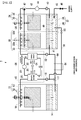
- FIG. 1 shows a configuration of a humidity control device 1 of an embodiment.
- the humidity control device 1 has: a processor 10 for controlling humidity by taking in air from a target space (the inside of a room) or the outside of a room and passing the taken-in air through a hygroscopic liquid L; a heat pump 20 for controlling the temperature of the hygroscopic liquid L in order for the processor 10 to perform the humidity control process; and a regenerator 30 for regenerating the hygroscopic liquid L used for the humidity control process in the processor 10.
- Lithium chloride (LiCl) is used as the hygroscopic liquid L in the embodiment.
- a solution of a deliquescent salt such as a saline solution a highly hygroscopic polyol such as glycerol, ethylene glycol, and propylene glycol, or other inexpensive hygroscopic liquid may be used as the hygroscopic liquid.
- a deliquescent salt such as a saline solution
- a highly hygroscopic polyol such as glycerol, ethylene glycol, and propylene glycol, or other inexpensive hygroscopic liquid may be used as the hygroscopic liquid.
- the processor 10 is indoor equipment for controlling the humidity of air in a room
- the regenerator 30 is outdoor equipment for regenerating the hygroscopic liquid L by giving and receiving moisture to and from outside air.
- Figure 1 shows an example where one regenerator 30 is connected to one processor 10
- the device may be configured so that one regenerator 30 is connected to a plurality of processors 10.
- the humidity control device 1 is installed in an apartment house, a big supermarket, or the like
- the device can be configured so that the processor 10 is installed in each room or on each floor and one regenerator 30 connected to the processors 10 is installed on the outside.
- the processor 10 and the regenerator 30 are connected to each other by a first hygroscopic-liquid pipe path 50 and a second hygroscopic-liquid pipe path 51.
- the first hygroscopic-liquid pipe path 50 is a pipe path for transferring the hygroscopic liquid L from the processor 10 to the regenerator 30, and the second hygroscopic-liquid pipe path 51 is a pipe path for transferring the hygroscopic liquid L from the regenerator 30 to the processor 10.
- the hygroscopic liquid L is circulated between the processor 10 and the regenerator 30 through the first hygroscopic-liquid pipe path 50 and second hygroscopic-liquid pipe path 51, and this allows the hygroscopic liquid L used by the processor 10 to be regenerated by the regenerator 30 and be returned to the processor 10.
- the processor 10 has an air processing unit 11 for performing a humidity control process by passing air through the hygroscopic liquid L, and a liquid tank 14 for containing the hygroscopic liquid L.
- the air processing unit 11 comprises a plurality of nozzles 12 for spraying the hygroscopic liquid L downward, and a filler 13 provided between the nozzles 12 and the liquid tank 14.
- the filler 13 is provided for the purpose of increasing contact area between the hygroscopic liquid L and air, and also of preventing the hygroscopic liquid L from splashing.
- a hydrophilic filtering medium, or a heat transfer fin made of copper, aluminum, or stainless steel may be used as the filler. While an example in which the hygroscopic liquid L is sprayed by means of the nozzles 12 is described in the embodiment, a configuration in which the hygroscopic liquid L is dropped on the filler 13 may be adopted.
- the processor 10 has a pipe 15 for supplying the hygroscopic liquid L present in the liquid tank 14 to the plurality of nozzles 12.
- a pump 16 is attached to the pipe 15, and the pump 16 sucks up the hygroscopic liquid L present in the liquid tank 14.
- the pipe 15 is also provided with a first heat exchanger 21 of the heat pump 20, and the first heat exchanger 21 heats or cools the hygroscopic liquid L.
- Whether the hygroscopic liquid L is heated or cooled depends on whether the processor 10 performs humidification or dehumidification. That is, when the processor 10 performs humidification, the hygroscopic liquid L is heated in order to make moisture contained in the hygroscopic liquid L be desorbed and taken in by air. On the other hand, when the processor 10 performs dehumidification, the hygroscopic liquid L is cooled in order to facilitate the absorption of moisture in air into the hygroscopic liquid L.
- the first hygroscopic-liquid pipe path 50 for transferring the hygroscopic liquid L present in the liquid tank 14 to the regenerator 30 is connected via a three-way valve 17 to the pipe 15 for sucking up the hygroscopic liquid L from the liquid tank 14.
- the three-way valve 17 controls the amount of the hygroscopic liquid L to be transferred to the air processing unit 11 of the processor 10 and the amount of the hygroscopic liquid L to be transferred through the first hygroscopic-liquid pipe path 50 to the regenerator 30.
- the three-way valve 17 controls so that (the amount of the hygroscopic liquid L to be transferred to the air processing unit 11):(the amount of the hygroscopic liquid L to be transferred to the regenerator 30) will be a ratio between 8:2 and 9:1.
- a second heat exchanger 22 of the heat pump 20 is provided in the first hygroscopic-liquid pipe path 50, and cools or heats the hygroscopic liquid L to be supplied to the regenerator 30.
- the heat pump 20 comprises the first heat exchanger 21, the second heat exchanger 22, a compressor 23, an expansion valve 24, and a refrigerant pipe 25 for connecting them to one another.
- the heat pump 20 can make the first heat exchanger 21 function as an evaporator or as a condenser by reversing the flow of the refrigerant.
- the second heat exchanger 22 performs an inverse process of the first heat exchanger 21.
- the regenerator 30 has a first regeneration processing unit 31 and second regeneration processing unit 34 for performing a regeneration process on the hygroscopic liquid L by passing air therethrough, and a liquid tank 37 for containing the hygroscopic liquid L.
- the first regeneration processing unit 31 comprises pluralities of nozzles 32a and 32b for spraying the hygroscopic liquid L downward, and a filler 33 provided below the nozzles 32a and 32b.
- the second regeneration processing unit 34 comprises a plurality of nozzles 35 for spraying the hygroscopic liquid L downward, and a filler 36 provided below the nozzles 35. While an example in which the hygroscopic liquid L is sprayed by means of the nozzles 32a and 32b is described in the embodiment, a configuration in which the hygroscopic liquid L is dropped on the filler 33 may be adopted.
- the liquid tank 37 of the regenerator 30 is partitioned by a partition 40 which is lower than the liquid level of the hygroscopic liquid L, so that a first tank 38 and a second tank 39 are formed.
- the height of the partition 40 can be designed as appropriate, and in the embodiment is 80% of the height of the liquid level.
- the second tank 39 is connected with the second hygroscopic-liquid pipe path 51, and the hygroscopic liquid L regenerated by the regenerator 30 is returned from the second tank 39 to the processor 10.
- the first regeneration processing unit 31 performs a regeneration process on the hygroscopic liquid L by spraying downward from the nozzles 32a the hygroscopic liquid L supplied from the first hygroscopic-liquid pipe path 50.
- the hygroscopic liquid L regeneration-processed by the first regeneration processing unit 31 enters the first tank 38.
- the first tank 38 is connected via a pipe 41 to the first hygroscopic-liquid pipe path 50. Part of the hygroscopic liquid L in the first tank 38 is supplied through the pipe 41 to the first hygroscopic-liquid pipe path 50, and is supplied through the second heat exchanger 22 to the first regeneration processing unit 31 again. With such circulation of the hygroscopic liquid L present in the first tank 38, the first regeneration processing unit 31 repeatedly performs the regeneration process on the hygroscopic liquid L.
- the partition 40 between the first tank 38 and the second tank 39 is lower than the liquid level, the hygroscopic liquid L in the first tank 38 flows into the second tank 39 as the hygroscopic liquid L supplied from the processor 10 enters the first tank 38.
- the regenerator 30 has a pipe 42 for supplying the hygroscopic liquid L present in the second tank 39 to the nozzles 32b or nozzles 35.
- the regenerator 30 can control a supply destination of the hygroscopic liquid L by means of a three-way valve 47 provided on the pipe 42.
- the three-way valve 47 may be switched so that the hygroscopic liquid L may be supplied to either one of the nozzles 32b or nozzles 35, or the amounts of the hygroscopic liquid L to be supplied from the three-way valve 47 to the nozzles 32b and nozzles 35 may be made to differ.
- the three-way valve 47 supplies the hygroscopic liquid L to the nozzles 35 during dehumidification operation, and supplies the hygroscopic liquid L to the nozzles 32b during humidification operation.
- a pump 43 is attached to the pipe 42, and it sucks up the hygroscopic liquid L present in the second tank 39.
- a heat source 44 is attached to this pipe 42, and it heats the hygroscopic liquid L sucked up from the second tank 39.
- the second regeneration processing unit 34 performs a regeneration process on the hygroscopic liquid L sucked up from the second tank 39.
- the hygroscopic liquid L regeneration-processed by the second regeneration processing unit 34 enters the second tank 39 again.
- the regenerator 30 has a water supply pipe 45 for supplying water to the second tank 39.
- the water supply pipe 45 is provided with a valve 46, which controls the water supply.
- the hygroscopic liquid L in the second tank 39 returns through the second hygroscopic-liquid pipe path 51 to the processor 10.
- the amount of the hygroscopic liquid L to return from the regenerator 30 to the processor 10 is controlled by a valve 53.
- the valve 53 controls the amount of the hygroscopic liquid L to be returned to the processor 10 so as to make the height of the liquid level of the hygroscopic liquid L in the liquid tank 37 be constant.
- the humidity control device 1 has a heat exchanger 54 for exchanging heat between the first hygroscopic-liquid pipe path 50 and the second hygroscopic-liquid pipe path 51.
- This heat exchanger 54 reduces the temperature difference between the hygroscopic liquid L flowing through the first hygroscopic-liquid pipe path 50 and the hygroscopic liquid L flowing through the second hygroscopic-liquid pipe path 51, and contributes to reducing the temperature difference between the hot and cold sides of the heat pump 20.
- FIG. 2 shows a dehumidification operation performed by the humidity control device 1 of the embodiment.
- the heat pump 20 is made to function with the first heat exchanger 21 as an evaporator and with the second heat exchanger 22 as a condenser.
- the hygroscopic liquid L of a high solution concentration is put in the liquid tank 14 of the processor 10.
- the processor 10 sucks up the hygroscopic liquid L of a high solution concentration from the liquid tank 14, cools the hygroscopic liquid L by means of the evaporator 21, and then supplies it to the air processing unit 11.
- the air processing unit 11 sprays the hygroscopic liquid L downward from the plurality of nozzles 12.
- the sprayed hygroscopic liquid L returns through the filler 13 to the liquid tank 14.
- the processor 10 takes in air from a target space or the outside thereof by means of a not shown fan, passes the air through the filler 13, and then discharges it into the target space. Since the hygroscopic liquid L of a high solution concentration and of a low temperature exists in the filler 13, moisture in air is absorbed by the hygroscopic liquid L, so that the discharged air is dehumidified. At the same time, heat exchange is also performed between the hygroscopic liquid L and the air, so that the discharged air is cooled.
- the hygroscopic liquid L is diluted and it becomes difficult for the hygroscopic liquid L to absorb moisture in air. This is why the hygroscopic liquid L is regenerated by the regenerator 30.
- the humidity control device 1 part of the hygroscopic liquid L sucked out from the liquid tank 14 of the processor 10 is supplied to the first hygroscopic-liquid pipe path 50, and is transferred to the regenerator 30. The amount of the hygroscopic liquid L to be transferred to the regenerator 30 is controlled by the three-way valve 17.
- the condenser 22 is provided in the middle of the first hygroscopic-liquid pipe path 50, and the hygroscopic liquid L to be transferred to the regenerator 30 is heated by the condenser 22.
- the regenerator 30 performs a regeneration process, by means of the first regeneration processing unit 31, on the hygroscopic liquid L which is supplied from the first hygroscopic-liquid pipe path 50 and whose solution concentration has decreased.
- the first regeneration processing unit 31 sprays the hygroscopic liquid L heated by the condenser 22 downward from the nozzles 32a.
- the sprayed hygroscopic liquid L enters the first tank 38 through the filler 33.
- the regenerator 30 takes in outside air by means of a not shown fan, and passes the air through the filler 33. Consequently, moisture is desorbed from the high-temperature hygroscopic liquid L existing in the filler 33 and containing much moisture and escapes into the air, so that the concentration of the hygroscopic liquid L increases.
- the hygroscopic liquid L processed by the first regeneration processing unit 31 enters the first tank 38.
- the hygroscopic liquid L that has entered the first tank 38 is supplied to the first hygroscopic-liquid pipe path 50, and also flows to the second tank 39.
- the hygroscopic liquid L supplied to the first hygroscopic-liquid pipe path 50 is heated by the condenser 22, and is supplied to the first regeneration processing unit 31 again.
- Such circulation of the hygroscopic liquid L between the first regeneration processing unit 31 and the first tank 38 allows the concentration of the hygroscopic liquid L to increase gradually.
- the regenerator 30 sucks up the hygroscopic liquid L present in the second tank 39.
- the three-way valve 47 opens the flow path to the nozzles 35 and closes the flow path to the nozzles 32b. Consequently, the hygroscopic liquid L heated by the heat source 44 is supplied to the second regeneration processing unit 34.
- the second regeneration processing unit 34 sprays the hygroscopic liquid L downward from the plurality of nozzles 35.
- the regenerator 30 takes in air and passes it through the filler 36, moisture is desorbed from the high-temperature hygroscopic liquid L existing in the filler 36 and containing much moisture and escapes into the air, so that the concentration of the hygroscopic liquid L increases.
- the sprayed hygroscopic liquid L returns through the filler 36 to the second tank 39.
- the temperature of the hygroscopic liquid L to be sprayed in the second regeneration processing unit 34 is raised by the heat source 44 and is higher than the temperature of the hygroscopic liquid L in the first regeneration processing unit 31. Accordingly, the hygroscopic liquid L sprayed from the nozzles 35 of the second regeneration processing unit 34 is in a state where moisture is more easily desorbed as compared to the hygroscopic liquid L sprayed from the nozzles 32a of the first regeneration processing unit 31, and the process of regenerating the hygroscopic liquid L advances further.
- the circulation of the hygroscopic liquid L between the second regeneration processing unit 34 and the second tank 39 allows the concentration of the hygroscopic liquid L to increase gradually, regenerating the hygroscopic liquid L.
- the regeneration-processed hygroscopic liquid L in the second tank 39 returns through the second hygroscopic-liquid pipe path 51 to the processor 10.
- the hygroscopic liquid L on the way back to the processor 10 decreases in temperature by heat exchange performed by the heat exchanger 54 with the hygroscopic liquid L flowing toward the regenerator 30.
- the humidity control device 1 of the embodiment adopts the configuration in which: the liquid tank 37 of the regenerator 30 is separated into the first tank 38 and the second tank 39 by the partition 40; and the heat source 44 is used for the process of regenerating the hygroscopic liquid L present in the second tank 39, but is not used for the process of regenerating the hygroscopic liquid L present in the first tank 38.
- This can suppress an increase in the temperature of the hygroscopic liquid L present in the first tank 38, suppressing an increase in the temperature of the hygroscopic liquid L supplied from the first tank 38 through the first hygroscopic-liquid pipe path 50 to the condenser 22, so that the temperature difference between the hot and cold sides of the heat pump 20 can be prevented from becoming large.
- the condenser 22 of the heat pump 20 has a function of dissipating heat absorbed in the evaporator 21.
- An increase in the temperature of the hygroscopic liquid L passing through the first hygroscopic-liquid pipe path 50 would cause an increase in the energy required for the heat dissipation of the heat pump 20, reducing energy utilization efficiency.
- the humidity control device 1 of the embodiment adopts the scheme for suppressing an increase in the temperature of the hygroscopic liquid L passing through the first hygroscopic-liquid pipe path 50 as described above, and therefore high energy utilization efficiency can be maintained even when the humidity control device 1 is continuously used.
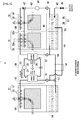
- FIG 3 shows a humidification operation performed by the humidity control device 1 of the embodiment.
- the humidity control device 1 performs humidification
- the heat pump 20 is made to function with the first heat exchanger 21 as a condenser and with the second heat exchanger 22 as an evaporator.
- the hygroscopic liquid L of a low solution concentration (containing much moisture) is put in the liquid tank of the processor 10. Basically, the humidification operation simply requires the opposite of the dehumidification operation.
- the processor 10 heats the hygroscopic liquid L of a low solution concentration and passes it through the filler 13, thereby desorbing moisture from the hygroscopic liquid L to humidify air. At the same time, heat exchange is also performed between the hygroscopic liquid L and the air, so that the discharged air is heated.
- the hygroscopic liquid L is concentrated and moisture released to air decreases. This is why the hygroscopic liquid L is regenerated by the regenerator 30.
- the humidity control device 1 part of the hygroscopic liquid L sucked out from the liquid tank 14 of the processor 10 is supplied to the first hygroscopic-liquid pipe path 50, and is transferred to the regenerator 30.
- the evaporator 22 is provided in the middle of the first hygroscopic-liquid pipe path 50, and the hygroscopic liquid L to be transferred to the regenerator 30 is cooled by the evaporator 22.
- the first regeneration processing unit 31 of the regenerator 30 passes the cooled high-concentration hygroscopic liquid L through the filler, thereby performing a regeneration process to make the hygroscopic liquid L absorb moisture, and puts the processed hygroscopic liquid L into the first tank 38.
- the hygroscopic liquid L that has entered the first tank 38 is supplied to the first hygroscopic-liquid pipe path 50, and also flows to the second tank 39.
- the hygroscopic liquid L supplied to the first hygroscopic-liquid pipe path 50 is cooled by the evaporator 22, and is supplied to the first regeneration processing unit 31 again.
- Such circulation of the hygroscopic liquid L between the first regeneration processing unit 31 and the first tank 38 allows the concentration of the hygroscopic liquid L to decrease gradually.
- the regenerator 30 sucks up the hygroscopic liquid L present in the second tank 39.
- the three-way valve 47 opens the flow path to the nozzles 32b and closes the flow path to the nozzles 35. Consequently, the hygroscopic liquid L sucked up from the second tank 39 and heated by the heat source 44 is supplied to the first regeneration processing unit 31.
- the hygroscopic liquid L is regenerated (diluted) by directly supplying water to the hygroscopic liquid L in addition to taking moisture from outside air into the hygroscopic liquid L.
- the regenerator 30 opens the valve 46 of the water supply pipe 45 to supply water to the second tank 39.
- the regenerator 30 also heats the hygroscopic liquid L by means of the heat source 44 if the water supply reduces the temperature of the hygroscopic liquid L.
- the regeneration-processed hygroscopic liquid L present in the second tank 39 returns through the second hygroscopic-liquid pipe path 51 to the processor 10.
- the humidity control device 1 of the embodiment supplies water to the second tank 39, the supplied water is mixed with a relatively large amount of the hygroscopic liquid L in the second tank 39, and a rapid decrease in the temperature of the hygroscopic liquid L due to the water supply can be prevented.
- the temperature of the hygroscopic liquid L increases as the hygroscopic liquid L absorbs water even when the temperature of the hygroscopic liquid L has decreased due to the water supply.
- the configuration of the embodiment preventing a rapid decrease in the temperature of the hygroscopic liquid L in the second tank 39 can prevent a rapid decrease in the temperature of the hygroscopic liquid supplied to the condenser 21. Consequently, the temperature of the hygroscopic liquid used in the processor 10 can be kept to perform humidification appropriately, and high energy utilization efficiency can be kept.
- the temperature of water supplied in winter when the humidification operation is performed is extremely low, thereby causing the temperature of the hygroscopic liquid L flowing through the second hygroscopic-liquid pipe path 51 to decrease rapidly, and the hygroscopic liquid L in that condition is supplied to the condenser 21 of the heat pump 20.
- the hygroscopic liquid L would not be able to be sufficiently heated by the condenser 21.
- the not sufficiently heated hygroscopic liquid L would be sprayed from the nozzles 12, an appropriate humidification would not be able to be performed, and energy utilization efficiency would decrease.
- the humidity control device 1 of the embodiment can solve such conventional problems.
- the humidity control device 1 of the embodiment supplies the hygroscopic liquid L sucked up from the second tank 39 to the first regeneration processing unit 31, and puts the processed hygroscopic liquid L into the first tank 38. Consequently, the hygroscopic liquid L which is heated by the heat source 44 and whose temperature is increased by heat of absorption enters the first tank 38, and is supplied from the first tank 38 through the pipe 41 to the evaporator 22.
- the supply of the high-temperature hygroscopic liquid L to the evaporator 22 facilitates the heat absorption by the evaporator 22, and can improve the energy utilization efficiency of the heat pump 20.
- the humidity control device 1 capable of performing both dehumidification and humidification has been described as an example, the invention can be applied to a humidity control device that only performs dehumidification or humidification.
- a humidity control device that exclusively performs dehumidification need not be provided with the water supply pipe 45 described in the above embodiment. If a humidity control device exclusively performs humidification, the liquid tank 37 need not be separated, but may also be a single liquid tank, in the configuration of the regenerator 30.
- first tank 38 and the second tank 39 are formed by partitioning the liquid tank 37 with the partition 40
- the first tank 38 and the second tank 39 may be configured to be independent and separate tanks.
- the first tank 38 and the second tank 39 may be configured so that the hygroscopic liquid L can move between the first tank 38 and the second tank 39 in an amount that does not cause the temperatures of the hygroscopic liquid L in the first tank 38 and that in the second tank 39 to even out easily, or so that the hygroscopic liquid L may flow only from the first tank 38 to the second tank 39.
- the configuration in which the hygroscopic liquid L flows only from the first tank 38 to the second tank 39 can be realized, for example, by inclining a pipe connecting both tanks 38 and 39 to each other toward the second tank 39.
- the invention has advantages of being able to keep the temperature difference between the hot and cold sides of the heat pump appropriately and maintain high energy utilization efficiency, and is useful as a humidity control device that uses a hygroscopic liquid to control the humidity, or the like.
Landscapes
- Chemical & Material Sciences (AREA)
- Engineering & Computer Science (AREA)
- Analytical Chemistry (AREA)
- General Chemical & Material Sciences (AREA)
- Oil, Petroleum & Natural Gas (AREA)
- Chemical Kinetics & Catalysis (AREA)
- Combustion & Propulsion (AREA)
- Mechanical Engineering (AREA)
- General Engineering & Computer Science (AREA)
- Drying Of Gases (AREA)
- Central Air Conditioning (AREA)
Applications Claiming Priority (2)
| Application Number | Priority Date | Filing Date | Title |
|---|---|---|---|
| JP2008134813A JP4384699B2 (ja) | 2008-05-22 | 2008-05-22 | 調湿装置 |
| PCT/JP2009/002149 WO2009141986A1 (ja) | 2008-05-22 | 2009-05-15 | 調湿装置 |
Publications (1)
| Publication Number | Publication Date |
|---|---|
| EP2309193A1 true EP2309193A1 (de) | 2011-04-13 |
Family
ID=41339926
Family Applications (1)
| Application Number | Title | Priority Date | Filing Date |
|---|---|---|---|
| EP09750348A Withdrawn EP2309193A1 (de) | 2008-05-22 | 2009-05-15 | Feuchtigkeitsregelvorrichtung |
Country Status (5)
| Country | Link |
|---|---|
| US (1) | US8171746B2 (de) |
| EP (1) | EP2309193A1 (de) |
| JP (1) | JP4384699B2 (de) |
| TW (1) | TW201007101A (de) |
| WO (1) | WO2009141986A1 (de) |
Cited By (8)
| Publication number | Priority date | Publication date | Assignee | Title |
|---|---|---|---|---|
| EP2407230A1 (de) * | 2010-07-16 | 2012-01-18 | Immoplan Technische Gebäudeausstattung | Verfahren zur Sorptionstrocknung unter Einsatz von Kaliumsalzen, Vorrichtung zur Durchführung des Verfahrens und Weiterverarbeitung der erhaltenden Verfahrenserzeugnisse |
| CN102901159A (zh) * | 2012-11-06 | 2013-01-30 | 刘拴强 | 溶液加热加湿空调机组 |
| EP2765362A4 (de) * | 2011-09-16 | 2015-07-01 | Daikin Ind Ltd | Vorrichtung zur feuchtigkeitsregelung |
| CN106500205A (zh) * | 2016-10-14 | 2017-03-15 | 浙江大学 | 跨临界循环与两级溶液除湿系统复合的空气处理系统 |
| WO2020250056A1 (en) * | 2019-06-12 | 2020-12-17 | Atlas Copco Airpower, Naamloze Vennootschap | Compressor system and method for supplying compressed gas |
| BE1027358B1 (nl) * | 2019-06-12 | 2021-01-18 | Atlas Copco Airpower Nv | Drooginrichting en werkwijze voor het drogen van gas en compressorinrichting voorzien van dergelijke drooginrichting |
| WO2023205016A1 (en) * | 2022-04-19 | 2023-10-26 | Copeland Lp | Desiccant heat exchanger for high efficiency dehumidification |
| US12337371B1 (en) | 2023-12-20 | 2025-06-24 | Copeland Lp | Systems and methods for assembling liquid desiccant air conditioner panels using flexible alignment features |
Families Citing this family (38)
| Publication number | Priority date | Publication date | Assignee | Title |
|---|---|---|---|---|
| JP4374393B1 (ja) * | 2008-05-27 | 2009-12-02 | ダイナエアー株式会社 | 調湿装置 |
| KR102107636B1 (ko) | 2010-05-25 | 2020-05-29 | 7에이씨 테크놀로지스, 아이엔씨. | 공조 및 다른 프로세스들을 위해 액체 흡습제들을 이용하는 방법들 및 시스템들 |
| TWI409417B (zh) * | 2010-12-17 | 2013-09-21 | Univ Nat Taiwan | 一種具有除濕溶液之空氣調節裝置 |
| JP2014525558A (ja) * | 2011-08-26 | 2014-09-29 | ディーユークール リミテッド | 乾燥剤ベースの冷房システム |
| CN102589072B (zh) * | 2012-03-21 | 2013-07-10 | 淄博一村空调有限公司 | 一种双介质循环冷暖加湿空调 |
| ES2755800T3 (es) | 2012-06-11 | 2020-04-23 | 7Ac Tech Inc | Métodos y sistemas para intercambiadores de calor turbulentos y resistentes a la corrosión |
| EP2881274B1 (de) * | 2012-08-05 | 2019-06-19 | Yokohama Heat use Technology | Entfeuchtungsvorrichtung für ein fahrzeug |
| EP2929256A4 (de) * | 2012-12-04 | 2016-08-03 | 7Ac Technologies Inc | Verfahren und systeme zum kühlen von gebäuden mit grosser wärmebelastung durch trockenmittelkühler |
| CN108443996B (zh) | 2013-03-01 | 2021-04-20 | 7Ac技术公司 | 干燥剂空气调节方法和系统 |
| EP2971984A4 (de) * | 2013-03-14 | 2017-02-01 | 7AC Technologies, Inc. | Verfahren und systeme zur nachrüstung einer klimaanlage mit einem flüssigen trocknungsmittel |
| EP2972009B1 (de) | 2013-03-14 | 2019-09-18 | 7AC Technologies, Inc. | Split-klimaanlage mit einem flüssigen trocknungsmittel |
| ES2759926T3 (es) | 2013-06-12 | 2020-05-12 | 7Ac Tech Inc | Sistema de aire acondicionado desecante líquido |
| NL2011617C2 (nl) * | 2013-10-15 | 2015-04-16 | Kea Consult B V | Systeem en werkwijze voor winning van warmte uit een gasstroom. |
| CN106062483B (zh) * | 2013-10-25 | 2019-06-11 | 艾尔研究公司 | 热泵除湿的增强方法 |
| US20150137394A1 (en) | 2013-11-18 | 2015-05-21 | Keith S. Reed | Air Humidification Injection Apparatus |
| US10323867B2 (en) | 2014-03-20 | 2019-06-18 | 7Ac Technologies, Inc. | Rooftop liquid desiccant systems and methods |
| CN104141992A (zh) * | 2014-07-09 | 2014-11-12 | 浙江理工大学 | 热泵驱动的膜式新风溶液除湿空调系统及方法 |
| CN107110525B (zh) | 2014-11-21 | 2020-02-11 | 7Ac技术公司 | 用于微分体液体干燥剂空气调节的方法和系统 |
| CN104613560B (zh) * | 2015-01-28 | 2017-10-27 | 中国科学院工程热物理研究所 | 一种低温热源和电联合驱动的双级溶液除湿系统 |
| CN106642442A (zh) * | 2015-11-03 | 2017-05-10 | 青岛海尔空调电子有限公司 | 一种湿度可调的新风空调系统 |
| CN106642421A (zh) * | 2015-11-03 | 2017-05-10 | 青岛海尔空调电子有限公司 | 新型一拖多空调除湿系统 |
| US10859295B2 (en) * | 2016-04-13 | 2020-12-08 | ZeoThermal Technologies, LLC | Cooling and heating platform |
| US10921001B2 (en) | 2017-11-01 | 2021-02-16 | 7Ac Technologies, Inc. | Methods and apparatus for uniform distribution of liquid desiccant in membrane modules in liquid desiccant air-conditioning systems |
| EP3704415A4 (de) | 2017-11-01 | 2021-11-03 | 7AC Technologies, Inc. | Tanksystem für eine klimaanlage mit flüssigtrockenmittel |
| CN110318232B (zh) * | 2018-03-30 | 2021-05-28 | 浙江三花智能控制股份有限公司 | 晾衣机 |
| US11022330B2 (en) | 2018-05-18 | 2021-06-01 | Emerson Climate Technologies, Inc. | Three-way heat exchangers for liquid desiccant air-conditioning systems and methods of manufacture |
| US11117090B2 (en) | 2018-11-26 | 2021-09-14 | Palo Alto Research Center Incorporated | Electrodialytic liquid desiccant dehumidifying system |
| FR3104452B1 (fr) * | 2019-12-13 | 2022-09-09 | Ifp Energies Now | Procede de regeneration d’une solution aqueuse de meg contenant des sels avec traitement de la purge |
| KR102401747B1 (ko) * | 2020-03-12 | 2022-05-24 | 한양대학교 산학협력단 | 공조 시스템 |
| US20220243932A1 (en) * | 2021-01-29 | 2022-08-04 | Palo Alto Research Center Incorporated | Electrochemical dehumidifier with multiple air contactors |
| US12085293B2 (en) | 2021-03-17 | 2024-09-10 | Mojave Energy Systems, Inc. | Staged regenerated liquid desiccant dehumidification systems |
| US11944934B2 (en) | 2021-12-22 | 2024-04-02 | Mojave Energy Systems, Inc. | Electrochemically regenerated liquid desiccant dehumidification system using a secondary heat pump |
| US12510257B2 (en) * | 2021-12-22 | 2025-12-30 | Mojave Energy Systems, Inc. | Electrochemically regenerated liquid desiccant dehumidification system using a secondary heat pump |
| US12571546B2 (en) | 2022-04-13 | 2026-03-10 | Mojave Energy Systems, Inc. | Liquid desiccant air conditioning using air as heat transfer medium |
| JP2025539498A (ja) | 2022-12-12 | 2025-12-05 | モハベ エネルギー システムズ,インコーポレイテッド | 液体乾燥剤空調システム及び制御方法 |
| EP4688222A2 (de) | 2023-04-07 | 2026-02-11 | Mojave Energy Systems, Inc. | Klimatisierungssysteme, -vorrichtungen und -verfahren mit einem trocknungsmittel mit extrem niedrigem durchfluss |
| SE2450659A1 (en) * | 2024-06-14 | 2025-12-15 | Airwatergreen Group Ab | System and method for controlling water content and temperature of an air stream |
| TWI912877B (zh) * | 2024-08-09 | 2026-01-21 | 財團法人工業技術研究院 | 液態除濕系統 |
Family Cites Families (13)
| Publication number | Priority date | Publication date | Assignee | Title |
|---|---|---|---|---|
| US4259849A (en) * | 1979-02-15 | 1981-04-07 | Midland-Ross Corporation | Chemical dehumidification system which utilizes a refrigeration unit for supplying energy to the system |
| JPS61138039A (ja) | 1984-12-11 | 1986-06-25 | Matsushita Electric Ind Co Ltd | 冷暖房装置 |
| JPH05332575A (ja) * | 1992-06-03 | 1993-12-14 | Daikin Ind Ltd | 洗浄回路付き湿度調節装置 |
| US6018954A (en) | 1995-04-20 | 2000-02-01 | Assaf; Gad | Heat pump system and method for air-conditioning |
| IL113446A (en) * | 1995-04-20 | 1998-04-05 | Assaf Gad | Heat pump system and a method for air conditioning |
| JP3037648B2 (ja) | 1997-10-24 | 2000-04-24 | 株式会社荏原製作所 | 除湿空調システム |
| JP3037649B2 (ja) | 1997-10-24 | 2000-04-24 | 株式会社荏原製作所 | 除湿空調システム |
| IL141579A0 (en) | 2001-02-21 | 2002-03-10 | Drykor Ltd | Dehumidifier/air-conditioning system |
| DE10059910C2 (de) | 2000-12-01 | 2003-01-16 | Daimler Chrysler Ag | Vorrichtung zur kontinuierlichen Befeuchtung und Entfeuchtung der Zuluft von Fertigungsprozessen oder Raumlufttechnik-Anlagen |
| JP4368212B2 (ja) | 2004-02-02 | 2009-11-18 | ダイナエアー株式会社 | 空調機 |
| JP2007253067A (ja) * | 2006-03-23 | 2007-10-04 | Tokyo Gas Co Ltd | 湿式除湿機 |
| JP2008111644A (ja) * | 2006-10-30 | 2008-05-15 | Shigeto Matsuo | エアコン廃熱利用液体デシカント装置 |
| JP4923981B2 (ja) | 2006-11-28 | 2012-04-25 | 株式会社豊田中央研究所 | 切削条件適正化装置、切削条件適正化方法、プログラム |
-
2008
- 2008-05-22 JP JP2008134813A patent/JP4384699B2/ja active Active
-
2009
- 2009-05-15 EP EP09750348A patent/EP2309193A1/de not_active Withdrawn
- 2009-05-15 US US12/992,690 patent/US8171746B2/en not_active Expired - Fee Related
- 2009-05-15 WO PCT/JP2009/002149 patent/WO2009141986A1/ja not_active Ceased
- 2009-05-18 TW TW098116375A patent/TW201007101A/zh unknown
Non-Patent Citations (1)
| Title |
|---|
| See references of WO2009141986A1 * |
Cited By (14)
| Publication number | Priority date | Publication date | Assignee | Title |
|---|---|---|---|---|
| EP2407230A1 (de) * | 2010-07-16 | 2012-01-18 | Immoplan Technische Gebäudeausstattung | Verfahren zur Sorptionstrocknung unter Einsatz von Kaliumsalzen, Vorrichtung zur Durchführung des Verfahrens und Weiterverarbeitung der erhaltenden Verfahrenserzeugnisse |
| US9874365B2 (en) | 2011-09-16 | 2018-01-23 | Daikin Industries, Ltd. | Humidity control apparatus |
| EP2765362A4 (de) * | 2011-09-16 | 2015-07-01 | Daikin Ind Ltd | Vorrichtung zur feuchtigkeitsregelung |
| CN102901159A (zh) * | 2012-11-06 | 2013-01-30 | 刘拴强 | 溶液加热加湿空调机组 |
| CN102901159B (zh) * | 2012-11-06 | 2015-03-11 | 刘拴强 | 溶液加热加湿空调机组 |
| CN106500205B (zh) * | 2016-10-14 | 2019-03-05 | 浙江大学 | 跨临界循环与两级溶液除湿系统复合的空气处理系统 |
| CN106500205A (zh) * | 2016-10-14 | 2017-03-15 | 浙江大学 | 跨临界循环与两级溶液除湿系统复合的空气处理系统 |
| WO2020250056A1 (en) * | 2019-06-12 | 2020-12-17 | Atlas Copco Airpower, Naamloze Vennootschap | Compressor system and method for supplying compressed gas |
| BE1027358B1 (nl) * | 2019-06-12 | 2021-01-18 | Atlas Copco Airpower Nv | Drooginrichting en werkwijze voor het drogen van gas en compressorinrichting voorzien van dergelijke drooginrichting |
| BE1027363B1 (nl) * | 2019-06-12 | 2021-01-20 | Atlas Copco Airpower Nv | Compressorinstallatie en werkwijze voor het leveren van samengeperst gas |
| US12209581B2 (en) | 2019-06-12 | 2025-01-28 | Atlas Copco Airpower, Naamloze Vennootschap | Compressor system and method for supplying compressed gas |
| WO2023205016A1 (en) * | 2022-04-19 | 2023-10-26 | Copeland Lp | Desiccant heat exchanger for high efficiency dehumidification |
| US12449141B2 (en) | 2022-04-19 | 2025-10-21 | Copeland Lp | Desiccant heat exchanger for high efficiency dehumidification |
| US12337371B1 (en) | 2023-12-20 | 2025-06-24 | Copeland Lp | Systems and methods for assembling liquid desiccant air conditioner panels using flexible alignment features |
Also Published As
| Publication number | Publication date |
|---|---|
| US20110101117A1 (en) | 2011-05-05 |
| JP4384699B2 (ja) | 2009-12-16 |
| TW201007101A (en) | 2010-02-16 |
| US8171746B2 (en) | 2012-05-08 |
| JP2009281668A (ja) | 2009-12-03 |
| WO2009141986A1 (ja) | 2009-11-26 |
Similar Documents
| Publication | Publication Date | Title |
|---|---|---|
| US8171746B2 (en) | Humidity control device | |
| US8047511B2 (en) | Humidity control device | |
| KR102223241B1 (ko) | 천장형 액체 흡습제 공조 시스템 | |
| JP5227840B2 (ja) | 調湿装置 | |
| CN110249184B (zh) | 调湿装置 | |
| JP2019215156A (ja) | ミニ分割液体デシカント空調のための方法及びシステム | |
| CN105164484A (zh) | 具有液体-空气薄膜能量交换器的蒸发冷却系统 | |
| CN1633575A (zh) | 除湿器/空调系统 | |
| CN111295552A (zh) | 空调装置以及空气调节方法 | |
| WO2006129544A1 (ja) | 空調システム | |
| JP2010036093A (ja) | 調湿装置 | |
| JP2009293831A (ja) | 調湿装置 | |
| JP2011092815A (ja) | 除湿装置 | |
| KR20120114012A (ko) | 하이브리드 공기조화 시스템 | |
| US12188681B2 (en) | Air treatment system | |
| JP2000230730A (ja) | 空気調和システム | |
| KR100735990B1 (ko) | 공기 조화 시스템 | |
| JP5349077B2 (ja) | 調湿装置 | |
| JP2013113575A (ja) | 調湿装置および調湿システム | |
| CN220473894U (zh) | 调湿模组及橱柜 | |
| JP2026008618A (ja) | 熱電冷却器を備えた閉ループ空調システム | |
| JP2000300933A (ja) | 除湿装置 | |
| JPH10205818A (ja) | 空調機及び空調システム | |
| NL7907751A (nl) | Inrichting voor luchtbehandeling. |
Legal Events
| Date | Code | Title | Description |
|---|---|---|---|
| PUAI | Public reference made under article 153(3) epc to a published international application that has entered the european phase |
Free format text: ORIGINAL CODE: 0009012 |
|
| 17P | Request for examination filed |
Effective date: 20101222 |
|
| AK | Designated contracting states |
Kind code of ref document: A1 Designated state(s): AT BE BG CH CY CZ DE DK EE ES FI FR GB GR HR HU IE IS IT LI LT LU LV MC MK MT NL NO PL PT RO SE SI SK TR |
|
| AX | Request for extension of the european patent |
Extension state: AL BA RS |
|
| DAX | Request for extension of the european patent (deleted) | ||
| STAA | Information on the status of an ep patent application or granted ep patent |
Free format text: STATUS: THE APPLICATION HAS BEEN WITHDRAWN |
|
| 18W | Application withdrawn |
Effective date: 20160405 |