EP2309901B1 - Dispositif pour chauffer et/ou faire mousser du lait pour des machines de préparation de boissons chaudes telles que des cappuccino - Google Patents
Dispositif pour chauffer et/ou faire mousser du lait pour des machines de préparation de boissons chaudes telles que des cappuccino Download PDFInfo
- Publication number
- EP2309901B1 EP2309901B1 EP08761365A EP08761365A EP2309901B1 EP 2309901 B1 EP2309901 B1 EP 2309901B1 EP 08761365 A EP08761365 A EP 08761365A EP 08761365 A EP08761365 A EP 08761365A EP 2309901 B1 EP2309901 B1 EP 2309901B1
- Authority
- EP
- European Patent Office
- Prior art keywords
- milk
- mixing chamber
- air
- tubular body
- steam
- Prior art date
- Legal status (The legal status is an assumption and is not a legal conclusion. Google has not performed a legal analysis and makes no representation as to the accuracy of the status listed.)
- Not-in-force
Links
- 239000008267 milk Substances 0.000 title claims abstract description 72
- 210000004080 milk Anatomy 0.000 title claims abstract description 72
- 235000013336 milk Nutrition 0.000 title claims abstract description 72
- 235000012171 hot beverage Nutrition 0.000 title claims abstract description 14
- 238000010438 heat treatment Methods 0.000 title claims abstract description 13
- 235000015116 cappuccino Nutrition 0.000 title claims abstract description 10
- 239000003570 air Substances 0.000 claims description 50
- 230000000694 effects Effects 0.000 claims description 8
- 230000008878 coupling Effects 0.000 claims description 5
- 238000010168 coupling process Methods 0.000 claims description 5
- 238000005859 coupling reaction Methods 0.000 claims description 5
- 238000005056 compaction Methods 0.000 claims description 4
- 239000012080 ambient air Substances 0.000 claims description 2
- 239000006260 foam Substances 0.000 description 6
- 230000001133 acceleration Effects 0.000 description 5
- 238000012986 modification Methods 0.000 description 3
- 230000004048 modification Effects 0.000 description 3
- 230000000670 limiting effect Effects 0.000 description 2
- 238000004519 manufacturing process Methods 0.000 description 2
- 238000005192 partition Methods 0.000 description 2
- 230000006978 adaptation Effects 0.000 description 1
- 230000001580 bacterial effect Effects 0.000 description 1
- 235000013361 beverage Nutrition 0.000 description 1
- 230000000903 blocking effect Effects 0.000 description 1
- 238000004140 cleaning Methods 0.000 description 1
- 235000013353 coffee beverage Nutrition 0.000 description 1
- 239000006071 cream Substances 0.000 description 1
- 238000003780 insertion Methods 0.000 description 1
- 230000037431 insertion Effects 0.000 description 1
- 239000007788 liquid Substances 0.000 description 1
- 230000033001 locomotion Effects 0.000 description 1
- 239000000463 material Substances 0.000 description 1
- 239000000203 mixture Substances 0.000 description 1
- 239000002245 particle Substances 0.000 description 1
- 230000002093 peripheral effect Effects 0.000 description 1
- 238000007789 sealing Methods 0.000 description 1
- 230000001954 sterilising effect Effects 0.000 description 1
- 238000004659 sterilization and disinfection Methods 0.000 description 1
- 239000002344 surface layer Substances 0.000 description 1
- 238000005406 washing Methods 0.000 description 1
- XLYOFNOQVPJJNP-UHFFFAOYSA-N water Substances O XLYOFNOQVPJJNP-UHFFFAOYSA-N 0.000 description 1
Images


Classifications
-
- A—HUMAN NECESSITIES
- A47—FURNITURE; DOMESTIC ARTICLES OR APPLIANCES; COFFEE MILLS; SPICE MILLS; SUCTION CLEANERS IN GENERAL
- A47J—KITCHEN EQUIPMENT; COFFEE MILLS; SPICE MILLS; APPARATUS FOR MAKING BEVERAGES
- A47J31/00—Apparatus for making beverages
- A47J31/44—Parts or details or accessories of beverage-making apparatus
- A47J31/4485—Nozzles dispensing heated and foamed milk, i.e. milk is sucked from a milk container, heated and foamed inside the device, and subsequently dispensed from the nozzle
-
- A—HUMAN NECESSITIES
- A47—FURNITURE; DOMESTIC ARTICLES OR APPLIANCES; COFFEE MILLS; SPICE MILLS; SUCTION CLEANERS IN GENERAL
- A47J—KITCHEN EQUIPMENT; COFFEE MILLS; SPICE MILLS; APPARATUS FOR MAKING BEVERAGES
- A47J31/00—Apparatus for making beverages
- A47J31/44—Parts or details or accessories of beverage-making apparatus
- A47J31/46—Dispensing spouts, pumps, drain valves or like liquid transporting devices
Definitions
- the present invention relates to a device for heating and/or frothing milk to prepare hot beverages such as a cappuccino.
- coffee making machines are provided with a device for dispensing steam at high temperature, by means of which milk is heated and/or frothed in order to prepare hot beverages, such as for example a cappuccino or a warm milk.
- this device In the jargon of the field, this device is known as frother.
- Known frothers comprise a tubular element in which the inlet end is associated with a source of steam at high temperature, and the outlet end is provided with a nozzle for dispensing the steam.
- known frothers comprise a tap for blocking and adjusting the flow of steam, which is provided with an actuation knob.
- an operator manually arranges the tubular element inside a container, such as a cup, jug or the like, which contains cold milk, and places the nozzle below or at the free surface of the milk, depending on whether he wishes to heat it or also froth it, i.e., produce a surface layer of foam.
- a container such as a cup, jug or the like, which contains cold milk
- the nozzle below or at the free surface of the milk, depending on whether he wishes to heat it or also froth it, i.e., produce a surface layer of foam.
- the operator then opens the tap and adjusts it according to his own sensibility in order to obtain in output from the nozzle a flow of steam which is suitable for the situation.
- the operator opens and closes the tap repeatedly as he simultaneously moves the container of the milk toward and away from the nozzle, so that the flow of steam incorporates air to form the foam.
- DE 10 2005 010599 discloses a device for heating and/or frothing milk, with a single tube for the supply of air and milk.
- EP 0 344 859 discloses a device for frothing and heating milk for beverages, wherein the air is sucked at the output, after the milk and vapor are mixed.
- the aim of the present invention is to devise a device for heating and/or frothing milk for machines for preparing hot beverages such as a cappuccino, whose operation is regular, constant and independent of the sensibility and experience of an operator, thus allowing to obtain milk which is warmed and/or frothed to a preset degree.
- An object of the present invention is to devise a device for heating and/or frothing milk which is versatile and flexible in use and can be installed easily on any machine for making hot beverages without requiring particular modifications or interventions for adaptation.
- Still another object of the present invention is to provide a device for heating and/or frothing milk which can be cleaned easily so as to ensure a high degree of hygiene.
- Another object of the present invention is to provide a device which is simple, relatively easy to provide in practice, safe in use, effective in operation, and relatively low in cost.
- the device according to the invention also comprises an ambient air supply duct, which has an intake port adapted to be connected to the outside environment and a port for introducing the air in the mixing chamber, the air being drawn into the mixing chamber due to the partial vacuum created by the flow of steam between the converging portion and the diverging portion of the Venturi tube.
- the device according to the invention comprises a tap which is associated with the air supply duct for opening and closing the air intake port.
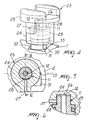
- the reference numeral 1 generally designates a device for heating and/or frothing milk for machines for preparing hot beverages such as cappuccino.
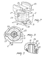
- the device 1 comprises a tubular body 2, inside which a Venturi tube is provided which comprises an intake end 3, a converging portion 4, a diverging portion 5 and a discharge end 6.
- the intake end 3 can be associated with a source of steam, such as for example a boiler, a pressurized boiler, an instant heat exchanger (Thermoblock).
- a source of steam such as for example a boiler, a pressurized boiler, an instant heat exchanger (Thermoblock).
- the flow of steam passes through the Venturi tube along the direction indicated by the arrow F.
- a chamber 7 for mixing the milk with the steam and optionally with air drawn from outside.
- the device 1 further comprises at least one milk supply duct 8, which has a drawing port 9 which can be associated with a milk reservoir, not shown, and a milk input port 10, which leads into the mixing chamber 7.
- the milk is drawn from the reservoir into the mixing chamber 7 due to the partial vacuum created by the acceleration of the flow of steam between the converging portion 4 and the diverging portion 5.
- the device 1 comprises at least one duct 11 for supplying air from the outside environment, which has an intake port 12 adapted to be connected to the outside environment and an air input port 13 which leads into the mixing chamber 7.
- the air is drawn from the outside into the mixing chamber 7 due to the partial vacuum created by the acceleration of the flow of steam between the converging portion 4 and the diverging portion 5.
- a dispenser 14 for the milk heated and/or frothed in the mixing chamber 7 is associated with the end of the tubular body 2 at which the discharge end 6 of the Venturi tube leads out.
- a chamber 15 for compacting the heated and/or frothed milk that exits from the mixing chamber 7 is defined between the diverging portion 5 and the dispenser 14.
- the milk supply duct 8 and the air supply duct 11 are connected to the tubular body 2 and are arranged substantially perpendicular to the longitudinal axis of the Venturi tube and are mutually offset with respect to the direction of the flow of steam.
- the milk input port 10 is offset backwardly with respect to the air input port 13.
- the mixing chamber 7 is defined by a cylindrical portion 7a, which is formed inside the tubular body 2 and is hollow and coaxial with respect to the Venturi tube, and by two surfaces 7b and 7c which are substantially frustum-shaped and face each other, so as to be opposite one another, within the cylindrical portion 7a.
- the two frustum-shaped surfaces 7b and 7c are arranged substantially coaxially to the cylindrical portion 7a and their respective smaller end faces are mutually juxtaposed and adjacent at a preset distance D.
- the milk input port 10 and the air input port 13 are provided at the lateral surface of the cylindrical portion 7a.
- the smaller end faces of the two mutually juxtaposed frustum-shaped surfaces 7b and 7c define the region at which the aspirated milk and air meet.
- the annular volume that lies at the peripheral portion of such region defines the space within which, due to turbulent motions, the milk is frothed by the air, forming foam.
- the Venturi tube comprises a first tubular portion 16, which connects the converging portion 4 to the mixing chamber 7, and a second tubular portion 17, which connects the mixing chamber 7 to the diverging portion 5.
- the first tubular portion 16 and the second tubular portion 17 are substantially coaxial, and the first portion has a smaller inside diameter than the second portion.
- the discharge end of the first tubular portion 16 and the intake end of the second tubular portion 17 are provided at the smaller end faces of the two frustum-shaped surfaces 7b and 7c which are mutually juxtaposed.
- the intake end 3, the converging portion 4 and the first tubular portion 16 of the Venturi tube are provided in a nozzle 18.
- the nozzle 18 has an end which is inserted detachably within the tubular body 2 with the interposition of sealing rings 19 and an opposite end which protrudes from the tubular body 2 and is provided with means for coupling or engagement with a machine for preparing hot beverages.
- the end of the nozzle 18 that is inserted within the tubular body 2 is frustum-shaped, so as to define the frustum-shaped surface 7b.
- the other frustum-shaped surface 7c is instead defined on one face of a partition which is formed within the tubular body 2 and is crossed by the second tubular portion 17.
- the diverging portion 5 is provided on the opposite face of such partition.
- the dispenser 14 is associated detachably with the tubular body 2 and comprises an internal cavity 20 which defines, in association with the tubular body 2, the compaction chamber 15 and is connected to a channel 21 for the outflow of the warmed and/or frothed milk.
- the outflow channel 21 is crossed by at least one longitudinal fin 22, which improves the flow of milk in output, contributing to give a "cream" effect to the frothed milk.
- Both the nozzle 18 and the dispenser 14 are coupled to the tubular body 2 by interlocking coupling or other temporary couplings which are known to the person skilled in the art.
- both the nozzle 18 and the dispenser 14 have an end which can be inserted substantially snugly within a corresponding open end of the tubular body 2, reference notches or tabs being further provided.
- the device 1 further comprises a tap 23, which is associated with the air supply duct 11 to open and close the air intake port 12.
- the tap 23 is of the "open/close” type; i.e., it assumes two configurations: an open configuration, in which the air intake port 12 is connected to the outside environment, and a closure configuration, in which the air intake port 12 is isolated with respect to the outside environment.
- the tap 23 could be replaced by any suitable air regulator elements or electrovalve.
- the air is aspirated into the mixing chamber 7 due to the partial vacuum created by the acceleration of the flow of steam in the converging portion 4 of the Venturi tube, so that the milk drawn into the mixing chamber 7, in addition to being heated by the steam, is also emulsified with the aspirated air and thus frothed, forming foam.
- any inflow of air into the mixing chamber 7 is prevented, so that the milk drawn into the mixing chamber 7 is only heated by the steam and is not also frothed.
- the tap 23 comprises a cup-shaped element 24, which is coupled rotatably to the end of the air supply duct 11, where the intake port 12 is provided, a gasket 25 being interposed between the cup-shaped element 24 and the air supply duct 11.
- a recess 28 is formed on the outer lateral surface of the air supply duct 11 and is connected to the interspace 26.
- an actuation handwheel 29 is provided, which is adapted to facilitate grip and handling by an operator.
- the cup-shaped element 24 turns between the open configuration and the closed configuration.
- the hole 27 engages the recess 28, so that the air can flow into the mixing chamber 7 along the path defined by the hole 27, by the interspace 26 and by the air supply duct 11.
- Means are also provided for stopping the rotation of the cup-shaped element 24 in the open configuration and in the closed configuration.
- These stop means comprise at least one tooth 30 which protrudes from the cup-shaped element 24 and is accommodated so that it can slide within a groove 31 defined in the tubular body 2, an abutment surface 32 and 33 of the tooth 30 being defined at each of the two opposite ends of the groove 31 in order to stop the cup-shaped element 24 respectively in the closed configuration and in the open configuration.
- the device 1 is applied to any machine for making hot beverages which has a high-temperature steam source; this application is facilitated by the coupling or insertion means provided at the end of the nozzle 18.
- the source of steam is connected to the intake end 3, while the milk supply duct 8 is connected, by means of a tube inserted therein, to a milk reservoir or container.
- the tap 23 is arranged in the closed configuration, in which the hole 27 does not engage the recess 28, preventing the inflow of air from the outside to the inside of the mixing chamber 7.
- the milk thus aspirated combines with the steam and warms up, and after passing through the compaction chamber 15 is dispensed through the outflow channel 21 of the dispenser 14.
- the partial vacuum generated by the acceleration that the flow of steam undergoes in passing through the converging portion 4 is such as to draw into the mixing chamber 7 not only the milk but also air.
- the milk thus frothed and heated passes through the compaction chamber 15, where it compacts again, to be then dispensed through the outflow channel 21 of the dispenser 14.
- the operations for cleaning the device 1 are particularly simple and effective; it is in fact sufficient to draw water instead of milk through the supply duct 8 in order to obtain, due to the heat of the flow of steam, the complete removal of any residue of milk and of any particle of dirt.
- the device according to the invention in fact allows to obtain warm and/or frothed milk at a degree and a level which are constant and independent of the sensibility and experience of the operator.
- the device according to the invention is simple to use and does not require particular manual skill of the operator; it is in fact sufficient to turn the tap in one of the two positions to obtain either warm milk or warm and frothed milk.
- the device according to the invention is flexible and versatile in use; it can in fact be applied to any machine without particular constructive constraints and without requiring particular structural modifications, and it can also operate arranged in any orientation.
- the device according to the invention ensures a high degree of hygiene and sterilization.
Landscapes
- Engineering & Computer Science (AREA)
- Food Science & Technology (AREA)
- Apparatus For Making Beverages (AREA)
Abstract
Claims (20)
- Dispositif (1) pour faire chauffer et/ou faire mousser du lait pour des machines de préparation de boissons chaudes, telles que les cappuccinos, comprenant un corps tubulaire (2) à l'intérieur duquel on trouve un tube de Venturi, qui a une extrémité d'admission (3) qui peut être associée à une source de vapeur et une extrémité de décharge (6), une chambre de mélange (7) qui est définie entre la partie convergente (4) et la partie divergente (5) dudit tube de Venturi, et au moins un conduit d'alimentation en lait (8), qui a un orifice d'aspiration (9) qui peut être associé à un réservoir de lait et un orifice (10) pour introduire le lait dans ladite chambre de mélange (7), le lait étant aspiré dans ladite chambre de mélange (7) en raison du vide partiel créé par l'écoulement de vapeur entre ladite partie convergente (4) et ladite partie divergente (5), caractérisé en ce que ladite chambre de mélange (7) est définie par une partie cylindrique (7a) qui est creuse et sensiblement coaxiale par rapport audit tube de Venturi, et par deux surfaces (7b, 7c) qui sont sensiblement de forme tronconique et font face à l'intérieur de ladite partie cylindrique et sont agencées de manière coaxiale à cette dernière et de sorte que leurs faces d'extrémité plus petites respectives sont mutuellement juxtaposées et adjacentes à une distance prédéterminée (D), lesdites deux surfaces tronconiques (7b, 7c) définissant deux parties de cône dont les sommets se font face.
- Dispositif selon la revendication 1, caractérisé en ce qu'il comprend au moins un conduit (11) pour fournir l'air ambiant qui a un orifice d'admission (12) raccordé à l'environnement extérieur et un orifice d'entrée (13) pour introduire l'air dans ladite chambre de mélange (7), l'air étant aspiré dans ladite chambre de mélange en raison du vide partiel créé par l'écoulement de ladite vapeur entre ladite partie convergente (4) et ladite partie divergente (5).
- Dispositif selon la revendication 1 ou 2, caractérisé en ce qu'il comprend un distributeur (14) du lait qui a été chauffé et/ou que l'on a fait mousser dans ladite chambre de mélange (7), qui est associé audit corps tubulaire (2) en aval, dans la direction de l'écoulement de ladite vapeur, de ladite extrémité de décharge (6) du tube de Venturi.
- Dispositif selon la revendication 3, caractérisé en ce qu'il comprend une chambre (15) pour compacter le lait chauffé et/ou que l'on a fait mousser, qui est définie entre ladite partie divergente (5) et ledit distributeur (14).
- Dispositif selon la revendication 1, caractérisé en ce que ledit orifice d'entrée de lait (10) est prévu sur la surface latérale de ladite partie cylindrique (7a).
- Dispositif selon la revendication 1 et selon une ou plusieurs des revendications 2 à 4, caractérisé en ce que ledit orifice d'entrée d'air (12) est prévu sur la surface latérale de ladite partie cylindrique (7a).
- Dispositif selon une ou plusieurs des revendications 2 à 6, caractérisé en ce que ledit orifice d'entrée de lait (10) est décalé vers l'arrière par rapport audit orifice d'entrée d'air (12) par rapport à la direction d'écoulement de la vapeur.
- Dispositif selon une ou plusieurs des revendications 2 à 7, caractérisé en ce que ledit conduit d'alimentation en lait (8) et ledit conduit d'alimentation en air (11) sont raccordés audit corps tubulaire (2) et sont agencés sensiblement en angle droit par rapport audit tube de Venturi.
- Dispositif selon une ou plusieurs des revendications précédentes, caractérisé en ce que ledit tube de Venturi comprend une première partie tubulaire (16) qui raccorde ladite partie convergente (4) à ladite chambre de mélange (7) et une seconde partie tubulaire (17) qui raccorde ladite chambre de mélange (7) à ladite partie divergente (5), ladite première partie tubulaire (16) et ladite seconde partie tubulaire (17) étant sensiblement coaxiales.
- Dispositif selon la revendication 9, caractérisé en ce que ladite première partie tubulaire (16) a un diamètre interne qui est inférieur au diamètre interne de ladite seconde partie tubulaire (17).
- Dispositif selon la revendication 9 ou 10, caractérisé en ce que ladite extrémité d'admission (3), ladite partie convergente (4) et ladite première partie tubulaire (16) du tube de Venturi sont définies dans une buse (18) qui a une extrémité insérée de manière détachable dans ledit corps tubulaire (2) et une extrémité opposée qui fait saillie à partir dudit corps tubulaire (2) et est prévue avec des moyens pour se coupler à une machine de préparation de boissons chaudes.
- Dispositif selon une ou plusieurs des revendications précédentes, caractérisé en ce que l'extrémité de ladite buse (18) qui est insérée dans ledit corps tubulaire (2) est de forme tronconique afin de définir l'une desdites surfaces de forme tronconique (7b, 7c).
- Dispositif selon la revendication 12, caractérisé en ce que l'autre desdites surfaces tronconiques (7b, 7c) et ladite seconde partie tubulaire (17) et ladite partie convergente (5) du tube de Venturi sont prévues dans ledit corps tubulaire (2).
- Dispositif selon une ou plusieurs des revendications 4 à 13, caractérisé en ce que ledit distributeur (14) est associé de manière détachable audit corps tubulaire (2) et comprend une cavité interne (20) qui définit, en association avec ledit corps tubulaire (2), ladite chambre de compactage (15) et est raccordé à un canal (21) pour la sortie du lait chaud et/ou que l'on a fait mousser.
- Dispositif selon la revendication 14, caractérisé en ce que ledit distributeur (14) comprend au moins une ailette longitudinale (22) qui passe à travers ledit canal de sortie (21).
- Dispositif selon une ou plusieurs des revendications 2 à 15, caractérisé en ce qu'il comprend un robinet (23) qui est associé audit conduit d'alimentation en air (11) pour ouvrir et fermer ledit orifice d'entrée d'air (12).
- Dispositif selon la revendication 16, caractérisé en ce que ledit robinet (23) comprend un élément en forme de coupelle (24) qui est couplé en rotation à l'extrémité dudit conduit d'alimentation en air (11) où ledit orifice d'entrée (12) est prévu, entre le fond dudit élément en forme de coupelle (24) et ladite extrémité dudit conduit d'alimentation en air (11), on trouve un espace intermédiaire (26), un trou de passage (27) qui passe à travers la paroi dudit élément en forme de coupelle (24), et un évidement (28) qui est défini sur la surface latérale externe dudit conduit d'alimentation en air (11) et est raccordé audit espace intermédiaire (28), ledit élément en forme de coupelle (24) étant mobile entre une configuration ouverte dans laquelle ledit trou (27) affecte ledit évidement (28) pour l'entrée de l'air provenant de l'extérieur dans l'orifice d'entrée (12) par ledit trou (27), ledit évidement (28) et ledit espace intermédiaire (26), et une configuration fermée, dans laquelle ledit trou (27) est exclu de l'évidement (28), empêchant l'entrée de l'air provenant de l'extérieur dans ledit orifice d'entrée (12).
- Dispositif selon la revendication 17, caractérisé en ce qu'il comprend des moyens (30) pour arrêter la rotation dudit élément en forme de coupelle (24) dans ladite configuration ouverte et dans ladite configuration fermée.
- Dispositif selon la revendication 18, caractérisé en ce que lesdits moyens d'arrêt (30) comprennent au moins une dent (30) qui s'étend à partir dudit élément en forme de coupelle (24) et est logée de sorte qu'il peut coulisser à l'intérieur d'une rainure (31) définie dans ledit corps tubulaire (2), au niveau de chacune des deux extrémités opposées de ladite rainure (31), on trouve une surface (32) pour la butée de ladite dent (30) afin d'arrêter ledit élément en forme de coupelle (24) respectivement dans ladite configuration ouverte et dans ladite configuration fermée.
- Machine pour préparer des boissons chaudes telles qu'un cappuccino ou similaire, comprenant une source de vapeur avec laquelle un dispositif (1) selon une ou plusieurs des revendications 1 à 19, est associé.
Priority Applications (1)
| Application Number | Priority Date | Filing Date | Title |
|---|---|---|---|
| PL08761365T PL2309901T3 (pl) | 2008-06-25 | 2008-06-25 | Urządzenie do ogrzewania i/lub spieniania mleka do maszyn do wytwarzania gorących napojów takich jak cappuccino |
Applications Claiming Priority (1)
| Application Number | Priority Date | Filing Date | Title |
|---|---|---|---|
| PCT/EP2008/058083 WO2009155972A1 (fr) | 2008-06-25 | 2008-06-25 | Dispositif pour chauffer et/ou faire mousser du lait pour des machines de préparation de boissons chaudes telles que des cappuccino |
Publications (2)
| Publication Number | Publication Date |
|---|---|
| EP2309901A1 EP2309901A1 (fr) | 2011-04-20 |
| EP2309901B1 true EP2309901B1 (fr) | 2012-08-22 |
Family
ID=40352074
Family Applications (1)
| Application Number | Title | Priority Date | Filing Date |
|---|---|---|---|
| EP08761365A Not-in-force EP2309901B1 (fr) | 2008-06-25 | 2008-06-25 | Dispositif pour chauffer et/ou faire mousser du lait pour des machines de préparation de boissons chaudes telles que des cappuccino |
Country Status (12)
| Country | Link |
|---|---|
| US (1) | US20110100230A1 (fr) |
| EP (1) | EP2309901B1 (fr) |
| JP (1) | JP2011525393A (fr) |
| KR (1) | KR20110031459A (fr) |
| CN (1) | CN102083347A (fr) |
| AU (1) | AU2008358302A1 (fr) |
| BR (1) | BRPI0822818A2 (fr) |
| CA (1) | CA2728847A1 (fr) |
| DK (1) | DK2309901T3 (fr) |
| ES (1) | ES2390390T3 (fr) |
| PL (1) | PL2309901T3 (fr) |
| WO (1) | WO2009155972A1 (fr) |
Families Citing this family (35)
| Publication number | Priority date | Publication date | Assignee | Title |
|---|---|---|---|---|
| PL2345354T3 (pl) * | 2010-01-19 | 2013-02-28 | Jura Elektroapparate Ag | Urządzenie dozujące do dozowania kawy i/lub mleka i/lub pianki mlecznej, urządzenie do przyrządzania napojów z takim urządzeniem dozującym oraz sposób składania urządzenia dozującego |
| RU2571198C2 (ru) * | 2010-06-18 | 2015-12-20 | Конинклейке Филипс Электроникс Н.В. | Устройство для вспенивания жидкости |
| IT1404234B1 (it) * | 2010-12-30 | 2013-11-15 | Sgl Italia S R L Con Unico Socio | Dispositivo cappuccinatore |
| ITBO20110555A1 (it) * | 2011-09-28 | 2013-03-29 | Flytek S R L | Dispositivo per l'erogazione di latte o altre bevande alimentari e loro schiume |
| JP6039688B2 (ja) * | 2011-12-29 | 2016-12-07 | コーニンクレッカ フィリップス エヌ ヴェKoninklijke Philips N.V. | 手動操作されるカップ内牛乳泡立て電気器具 |
| US9016670B2 (en) * | 2012-03-26 | 2015-04-28 | B/E Aerospace, Inc. | Froth wand for espresso maker |
| CN103519683A (zh) * | 2012-07-03 | 2014-01-22 | 苏州工业园区咖乐美电器有限公司 | 一种奶泡器 |
| BR112015000334A2 (pt) * | 2012-07-12 | 2017-06-27 | Koninklijke Philips Nv | dispositivo de formação de espuma em um líquido por meio de interação com um gás, dispositivo de preparo de bebidas e cafeteira |
| CN202714725U (zh) * | 2012-08-08 | 2013-02-06 | 漳州灿坤实业有限公司 | 一种具有自动清洗功能的奶泡机 |
| CN103844903A (zh) * | 2012-11-30 | 2014-06-11 | 苏州工业园区咖乐美电器有限公司 | 一种咖啡机奶泡器 |
| KR101489907B1 (ko) * | 2013-01-07 | 2015-02-06 | 주식회사 유일코리아 | 커피 머신의 우유거품 발생장치 |
| CN203468337U (zh) * | 2013-10-08 | 2014-03-12 | 漳州灿坤实业有限公司 | 一种便于清洗的起泡装置 |
| WO2015078858A1 (fr) | 2013-11-28 | 2015-06-04 | Koninklijke Philips N.V. | Dispositif de moussage de boisson et recipient comprenant ledit dispositif |
| CN103637691B (zh) * | 2013-12-20 | 2015-11-11 | 芮秋婷 | 一种气流式咖啡机机头 |
| EP2896332B1 (fr) * | 2014-01-15 | 2016-08-17 | De'Longhi Appliances S.r.l. | Dispositif pouvant être associé à une buse de distribution de vapeur d'une machine à café pour la production d'une boisson lactée |
| CN103989405B (zh) * | 2014-04-11 | 2016-10-05 | 宁波全景电器技术有限公司 | 自动产生泡沫牛奶的牛奶发泡装置 |
| EP2944237A1 (fr) * | 2014-05-14 | 2015-11-18 | Jura Elektroapparate Ag | Dispositif d'écoulement pour un dispositif de mousse de lait |
| FR3021200B1 (fr) * | 2014-05-23 | 2016-12-09 | Seb Sa | Dispositif de production de boissons a base de lait muni d’un systeme d’accouplement et machine a cafe comportant un tel dispositif |
| FR3021197B1 (fr) * | 2014-05-23 | 2016-05-13 | Seb Sa | Dispositif de production de boissons a base de lait muni de moyens de securite et machine a cafe comportant un tel dispositif |
| CA2953409A1 (fr) * | 2014-06-27 | 2015-12-30 | Illycaffe' Spa | Machine de preparation de boissons avec mousse de lait, en particulier cappuccino ou macchiato latte |
| AU2016294516A1 (en) | 2015-07-15 | 2018-02-08 | Gary Rayner | Systems and methods for producing a foamable and/or flowable material for consumption |
| CN108024658B (zh) * | 2015-09-25 | 2021-10-12 | 雀巢产品有限公司 | 起泡设备 |
| US20170095107A1 (en) * | 2015-10-01 | 2017-04-06 | Jen-Hui Chen | Drip portable cup |
| JP6675070B2 (ja) * | 2016-03-10 | 2020-04-01 | パナソニックIpマネジメント株式会社 | 飲料製造装置 |
| JP6650598B2 (ja) * | 2016-03-10 | 2020-02-19 | パナソニックIpマネジメント株式会社 | 飲料製造装置 |
| ITUA20162804A1 (it) * | 2016-04-21 | 2017-10-21 | De Longhi Appliances Srl | Dispositivo per la preparazione di una bevanda a base di latte |
| CN106136889A (zh) * | 2016-07-22 | 2016-11-23 | 宁波全景电器技术有限公司 | 一种牛奶泡沫产生装置 |
| IT201600096851A1 (it) * | 2016-09-27 | 2018-03-27 | De Longhi Appliances Srl | Dispositivo di emulsione di latte ad effetto venturi e metodo di produzione di latte caldo con e senza schiuma con un tale dispositivo |
| CN106235889B (zh) * | 2016-10-10 | 2018-11-23 | 苏州工业园区咖乐美电器有限公司 | 一种双奶沫器系统 |
| IT201800001717A1 (it) * | 2018-01-24 | 2019-07-24 | De Longhi Appliances Srl | Dispositivo per il riscaldamento e l’emulsione di bevande |
| RU185076U1 (ru) * | 2018-06-27 | 2018-11-20 | Общество с ограниченной ответственностью "ПОЛАРИС ИНТЕРНЕЙШНЛ ЛИМИТЕД" | Сборно-разборная паровая трубка для кофемашины |
| EP3841934A1 (fr) * | 2019-12-24 | 2021-06-30 | Koninklijke Philips N.V. | Appareil de mélange |
| EP4018887A1 (fr) * | 2020-12-24 | 2022-06-29 | Koninklijke Philips N.V. | Appareil mélangeur |
| IT202100003017A1 (it) * | 2021-02-11 | 2022-08-11 | De Longhi Appliances Srl | Montalatte a migliorata facilità di accesso alle sue parti interne per la pulizia |
| CN117137327A (zh) * | 2023-09-22 | 2023-12-01 | 中山市金弘电器有限公司 | 一种发泡模组及咖啡机奶泡装置 |
Family Cites Families (19)
| Publication number | Priority date | Publication date | Assignee | Title |
|---|---|---|---|---|
| US2916044A (en) * | 1956-09-18 | 1959-12-08 | Phelan | Cover and serving valve for freezers |
| IT1215793B (it) * | 1988-02-04 | 1990-02-22 | Alberto Siccardi | Dispositivo automatico perl'ottenimento di latte schiumoso. |
| DE68908275T2 (de) | 1988-06-01 | 1994-01-20 | Lucio Grossi | Vorrichtung zum Schäumen und Erhitzen von Milch für Getränke. |
| US5477885A (en) * | 1991-11-29 | 1995-12-26 | Masco Corporation | Flow rate and temperature limiting mechanism for a mixing valve |
| DE4220986A1 (de) * | 1992-06-26 | 1994-01-05 | Gotthard Dipl Ing Mahlich | Vorrichtung zum Zubereiten von Milchschaum für Cappuccino |
| CH689933A5 (it) * | 1994-12-27 | 2000-02-15 | Lough J Ltd | Gruppo emulsionatore particolarmente per emulsionare vapore e latte per la preparazione di cappuccini e simili. |
| IT240604Y1 (it) * | 1996-04-17 | 2001-04-02 | Quick Italia S R L | Dispositivo emulsionatore sterilizzabile |
| IT240748Y1 (it) * | 1996-06-21 | 2001-04-11 | Grossi Lucio | Dispositivo emulsionatore e riscaldatore di liquidi, quali latte esimili, dotato di canali longitudinali di aspirazione dell'aria |
| US5738002A (en) * | 1996-11-04 | 1998-04-14 | Marano-Ducarne; Anthony | Self-cleaning espresso machine attachment for producing frothed hot milk |
| WO1999031416A1 (fr) * | 1997-12-18 | 1999-06-24 | Amerikam, Inc. | Valve en ligne |
| DE29817116U1 (de) * | 1998-09-24 | 1998-12-17 | Jura Elektroapparate Ag, Niederbuchsiten | Vorrichtung zur Erzeugung von Milchschaum für Cappuccino |
| US6024120A (en) * | 1998-09-25 | 2000-02-15 | Sherwood Services Ag | Pressure relief valve with moving diaphragm |
| US6361025B1 (en) * | 2000-04-11 | 2002-03-26 | Hydro-Thermal Corporation | Steam injection heater with transverse mounted mach diffuser |
| DE20204085U1 (de) * | 2002-03-13 | 2002-05-23 | Eugster/Frismag Ag, Romanshorn | Vorrichtung zur Erzeugung von Milchschaum für Cappuccino |
| WO2005032316A1 (fr) * | 2003-10-06 | 2005-04-14 | Fabrizia Di Giampaolo | Dispositif de production d'une emulsion de lait et d'air chauffee sterilisable |
| ITMI20040777A1 (it) * | 2004-04-21 | 2004-07-21 | De Longhi Spa | Dispositivo e procedimento per la produzione di una bevanda a base di latte |
| DE102005010599A1 (de) | 2004-05-18 | 2006-09-14 | Nestec S.A. | Vorrichtung zum Aufschäumen von Milch mit externer Milchansaugung und direkter Ankoppelung an die Dampfzuleitung |
| PT1746920E (pt) * | 2004-05-18 | 2010-05-28 | Nestec Sa | Dispositivo para produção de espuma de leite com dispositivo de sucção de leite externo |
| DE602005007183D1 (de) * | 2005-04-25 | 2008-07-10 | Nestec Sa | Aufschäumvorrichtung mit Schaumstromregelung |
-
2008
- 2008-06-25 BR BRPI0822818-3A patent/BRPI0822818A2/pt not_active IP Right Cessation
- 2008-06-25 JP JP2011515124A patent/JP2011525393A/ja active Pending
- 2008-06-25 WO PCT/EP2008/058083 patent/WO2009155972A1/fr not_active Ceased
- 2008-06-25 US US13/001,158 patent/US20110100230A1/en not_active Abandoned
- 2008-06-25 EP EP08761365A patent/EP2309901B1/fr not_active Not-in-force
- 2008-06-25 KR KR1020117000781A patent/KR20110031459A/ko not_active Withdrawn
- 2008-06-25 ES ES08761365T patent/ES2390390T3/es active Active
- 2008-06-25 AU AU2008358302A patent/AU2008358302A1/en not_active Abandoned
- 2008-06-25 DK DK08761365.9T patent/DK2309901T3/da active
- 2008-06-25 PL PL08761365T patent/PL2309901T3/pl unknown
- 2008-06-25 CA CA2728847A patent/CA2728847A1/fr not_active Abandoned
- 2008-06-25 CN CN2008801301210A patent/CN102083347A/zh active Pending
Also Published As
| Publication number | Publication date |
|---|---|
| DK2309901T3 (da) | 2012-12-10 |
| US20110100230A1 (en) | 2011-05-05 |
| CN102083347A (zh) | 2011-06-01 |
| KR20110031459A (ko) | 2011-03-28 |
| EP2309901A1 (fr) | 2011-04-20 |
| ES2390390T3 (es) | 2012-11-12 |
| BRPI0822818A2 (pt) | 2015-06-30 |
| WO2009155972A1 (fr) | 2009-12-30 |
| CA2728847A1 (fr) | 2009-12-30 |
| AU2008358302A1 (en) | 2009-12-30 |
| PL2309901T3 (pl) | 2013-01-31 |
| JP2011525393A (ja) | 2011-09-22 |
Similar Documents
| Publication | Publication Date | Title |
|---|---|---|
| EP2309901B1 (fr) | Dispositif pour chauffer et/ou faire mousser du lait pour des machines de préparation de boissons chaudes telles que des cappuccino | |
| EP2672865B1 (fr) | Dispositif de mélange, de chauffage et/ou de formation de mousse pour machines de préparation de boissons chaudes, en particulier de cappuccino | |
| US12538997B2 (en) | Cleaning system and method for beverage appliance | |
| RU2526011C2 (ru) | Устройство для получения молочной пены | |
| US9414711B2 (en) | Coffee machine | |
| EP2153759B1 (fr) | Dispositif de production de boisson à base de lait | |
| EP2994026B1 (fr) | Bidon pour boissons et machine de production de boisson comprenant ledit bidon | |
| JP6336076B2 (ja) | 飲料泡立て装置及びこの装置を有するジャグ | |
| PT791321E (pt) | Maquina de cafe expresso equipada com um dispositivo de producao de espuma de leite | |
| US20110005407A1 (en) | Beverage preparation machine and method for cleaning a beverage preparation machine | |
| JP7200236B2 (ja) | 飲料自動販売機 | |
| ITMI20101334A1 (it) | Contenitore del latte associabile all erogatore di vapore e/o acqua di una macchina da caffè, macchina da caffè che presenta detto contenitore, e metodo di lavaggio di detto contenitore | |
| US20200163486A1 (en) | Steam milk frother | |
| WO2008128609A1 (fr) | Cafetière extrêmement flexible pour la production d'une boisson à base de café | |
| CN108024658A (zh) | 起泡设备 | |
| JP5144521B2 (ja) | 少なくとも2つの流体に基づいて飲料を調製するプロセスにおける使用のための飲料作成ユニット | |
| WO2009071247A1 (fr) | Dispositif de production de mousse de lait ou similaire | |
| CN101969824B (zh) | 包括具有用于输送流体饮料成分的至少一个管道的易清洁管道系统的饮料制作机 | |
| CN116249467A (zh) | 例如产生起泡奶液的混合装置 |
Legal Events
| Date | Code | Title | Description |
|---|---|---|---|
| PUAI | Public reference made under article 153(3) epc to a published international application that has entered the european phase |
Free format text: ORIGINAL CODE: 0009012 |
|
| 17P | Request for examination filed |
Effective date: 20101210 |
|
| AK | Designated contracting states |
Kind code of ref document: A1 Designated state(s): AT BE BG CH CY CZ DE DK EE ES FI FR GB GR HR HU IE IS IT LI LT LU LV MC MT NL NO PL PT RO SE SI SK TR |
|
| AX | Request for extension of the european patent |
Extension state: AL BA MK RS |
|
| 17Q | First examination report despatched |
Effective date: 20110812 |
|
| DAX | Request for extension of the european patent (deleted) | ||
| REG | Reference to a national code |
Ref country code: HK Ref legal event code: DE Ref document number: 1152211 Country of ref document: HK |
|
| GRAP | Despatch of communication of intention to grant a patent |
Free format text: ORIGINAL CODE: EPIDOSNIGR1 |
|
| RAP1 | Party data changed (applicant data changed or rights of an application transferred) |
Owner name: SWISS CAFFE ASIA LTD |
|
| GRAS | Grant fee paid |
Free format text: ORIGINAL CODE: EPIDOSNIGR3 |
|
| GRAA | (expected) grant |
Free format text: ORIGINAL CODE: 0009210 |
|
| AK | Designated contracting states |
Kind code of ref document: B1 Designated state(s): AT BE BG CH CY CZ DE DK EE ES FI FR GB GR HR HU IE IS IT LI LT LU LV MC MT NL NO PL PT RO SE SI SK TR |
|
| REG | Reference to a national code |
Ref country code: GB Ref legal event code: FG4D |
|
| REG | Reference to a national code |
Ref country code: CH Ref legal event code: EP |
|
| REG | Reference to a national code |
Ref country code: IE Ref legal event code: FG4D |
|
| REG | Reference to a national code |
Ref country code: AT Ref legal event code: REF Ref document number: 571451 Country of ref document: AT Kind code of ref document: T Effective date: 20120915 |
|
| REG | Reference to a national code |
Ref country code: NL Ref legal event code: T3 |
|
| REG | Reference to a national code |
Ref country code: DE Ref legal event code: R096 Ref document number: 602008018217 Country of ref document: DE Effective date: 20121018 |
|
| REG | Reference to a national code |
Ref country code: CH Ref legal event code: NV Representative=s name: PATENTANWAELTE SCHAAD, BALASS, MENZL & PARTNER AG |
|
| REG | Reference to a national code |
Ref country code: ES Ref legal event code: FG2A Ref document number: 2390390 Country of ref document: ES Kind code of ref document: T3 Effective date: 20121112 |
|
| REG | Reference to a national code |
Ref country code: SE Ref legal event code: TRGR |
|
| REG | Reference to a national code |
Ref country code: DK Ref legal event code: T3 |
|
| REG | Reference to a national code |
Ref country code: LT Ref legal event code: MG4D Effective date: 20120822 |
|
| PG25 | Lapsed in a contracting state [announced via postgrant information from national office to epo] |
Ref country code: LT Free format text: LAPSE BECAUSE OF FAILURE TO SUBMIT A TRANSLATION OF THE DESCRIPTION OR TO PAY THE FEE WITHIN THE PRESCRIBED TIME-LIMIT Effective date: 20120822 Ref country code: NO Free format text: LAPSE BECAUSE OF FAILURE TO SUBMIT A TRANSLATION OF THE DESCRIPTION OR TO PAY THE FEE WITHIN THE PRESCRIBED TIME-LIMIT Effective date: 20121122 Ref country code: HR Free format text: LAPSE BECAUSE OF FAILURE TO SUBMIT A TRANSLATION OF THE DESCRIPTION OR TO PAY THE FEE WITHIN THE PRESCRIBED TIME-LIMIT Effective date: 20120822 Ref country code: FI Free format text: LAPSE BECAUSE OF FAILURE TO SUBMIT A TRANSLATION OF THE DESCRIPTION OR TO PAY THE FEE WITHIN THE PRESCRIBED TIME-LIMIT Effective date: 20120822 Ref country code: IS Free format text: LAPSE BECAUSE OF FAILURE TO SUBMIT A TRANSLATION OF THE DESCRIPTION OR TO PAY THE FEE WITHIN THE PRESCRIBED TIME-LIMIT Effective date: 20121222 |
|
| REG | Reference to a national code |
Ref country code: PL Ref legal event code: T3 |
|
| PG25 | Lapsed in a contracting state [announced via postgrant information from national office to epo] |
Ref country code: LV Free format text: LAPSE BECAUSE OF FAILURE TO SUBMIT A TRANSLATION OF THE DESCRIPTION OR TO PAY THE FEE WITHIN THE PRESCRIBED TIME-LIMIT Effective date: 20120822 Ref country code: GR Free format text: LAPSE BECAUSE OF FAILURE TO SUBMIT A TRANSLATION OF THE DESCRIPTION OR TO PAY THE FEE WITHIN THE PRESCRIBED TIME-LIMIT Effective date: 20121123 Ref country code: SI Free format text: LAPSE BECAUSE OF FAILURE TO SUBMIT A TRANSLATION OF THE DESCRIPTION OR TO PAY THE FEE WITHIN THE PRESCRIBED TIME-LIMIT Effective date: 20120822 Ref country code: PT Free format text: LAPSE BECAUSE OF FAILURE TO SUBMIT A TRANSLATION OF THE DESCRIPTION OR TO PAY THE FEE WITHIN THE PRESCRIBED TIME-LIMIT Effective date: 20121224 |
|
| PG25 | Lapsed in a contracting state [announced via postgrant information from national office to epo] |
Ref country code: RO Free format text: LAPSE BECAUSE OF FAILURE TO SUBMIT A TRANSLATION OF THE DESCRIPTION OR TO PAY THE FEE WITHIN THE PRESCRIBED TIME-LIMIT Effective date: 20120822 Ref country code: CZ Free format text: LAPSE BECAUSE OF FAILURE TO SUBMIT A TRANSLATION OF THE DESCRIPTION OR TO PAY THE FEE WITHIN THE PRESCRIBED TIME-LIMIT Effective date: 20120822 Ref country code: EE Free format text: LAPSE BECAUSE OF FAILURE TO SUBMIT A TRANSLATION OF THE DESCRIPTION OR TO PAY THE FEE WITHIN THE PRESCRIBED TIME-LIMIT Effective date: 20120822 |
|
| PG25 | Lapsed in a contracting state [announced via postgrant information from national office to epo] |
Ref country code: SK Free format text: LAPSE BECAUSE OF FAILURE TO SUBMIT A TRANSLATION OF THE DESCRIPTION OR TO PAY THE FEE WITHIN THE PRESCRIBED TIME-LIMIT Effective date: 20120822 |
|
| PLBE | No opposition filed within time limit |
Free format text: ORIGINAL CODE: 0009261 |
|
| STAA | Information on the status of an ep patent application or granted ep patent |
Free format text: STATUS: NO OPPOSITION FILED WITHIN TIME LIMIT |
|
| 26N | No opposition filed |
Effective date: 20130523 |
|
| PG25 | Lapsed in a contracting state [announced via postgrant information from national office to epo] |
Ref country code: BG Free format text: LAPSE BECAUSE OF FAILURE TO SUBMIT A TRANSLATION OF THE DESCRIPTION OR TO PAY THE FEE WITHIN THE PRESCRIBED TIME-LIMIT Effective date: 20121122 |
|
| REG | Reference to a national code |
Ref country code: DE Ref legal event code: R097 Ref document number: 602008018217 Country of ref document: DE Effective date: 20130523 |
|
| PG25 | Lapsed in a contracting state [announced via postgrant information from national office to epo] |
Ref country code: CY Free format text: LAPSE BECAUSE OF FAILURE TO SUBMIT A TRANSLATION OF THE DESCRIPTION OR TO PAY THE FEE WITHIN THE PRESCRIBED TIME-LIMIT Effective date: 20120822 |
|
| PG25 | Lapsed in a contracting state [announced via postgrant information from national office to epo] |
Ref country code: MC Free format text: LAPSE BECAUSE OF FAILURE TO SUBMIT A TRANSLATION OF THE DESCRIPTION OR TO PAY THE FEE WITHIN THE PRESCRIBED TIME-LIMIT Effective date: 20120822 |
|
| REG | Reference to a national code |
Ref country code: IE Ref legal event code: MM4A |
|
| PG25 | Lapsed in a contracting state [announced via postgrant information from national office to epo] |
Ref country code: IE Free format text: LAPSE BECAUSE OF NON-PAYMENT OF DUE FEES Effective date: 20130625 |
|
| PGFP | Annual fee paid to national office [announced via postgrant information from national office to epo] |
Ref country code: GB Payment date: 20140603 Year of fee payment: 7 |
|
| PGFP | Annual fee paid to national office [announced via postgrant information from national office to epo] |
Ref country code: SE Payment date: 20140624 Year of fee payment: 7 Ref country code: AT Payment date: 20140620 Year of fee payment: 7 |
|
| PGFP | Annual fee paid to national office [announced via postgrant information from national office to epo] |
Ref country code: DK Payment date: 20140625 Year of fee payment: 7 |
|
| REG | Reference to a national code |
Ref country code: PL Ref legal event code: LAPE |
|
| PGFP | Annual fee paid to national office [announced via postgrant information from national office to epo] |
Ref country code: BE Payment date: 20140618 Year of fee payment: 7 Ref country code: NL Payment date: 20140627 Year of fee payment: 7 |
|
| PG25 | Lapsed in a contracting state [announced via postgrant information from national office to epo] |
Ref country code: PL Free format text: LAPSE BECAUSE OF NON-PAYMENT OF DUE FEES Effective date: 20130625 |
|
| PG25 | Lapsed in a contracting state [announced via postgrant information from national office to epo] |
Ref country code: MT Free format text: LAPSE BECAUSE OF FAILURE TO SUBMIT A TRANSLATION OF THE DESCRIPTION OR TO PAY THE FEE WITHIN THE PRESCRIBED TIME-LIMIT Effective date: 20120822 |
|
| PG25 | Lapsed in a contracting state [announced via postgrant information from national office to epo] |
Ref country code: TR Free format text: LAPSE BECAUSE OF FAILURE TO SUBMIT A TRANSLATION OF THE DESCRIPTION OR TO PAY THE FEE WITHIN THE PRESCRIBED TIME-LIMIT Effective date: 20120822 |
|
| PG25 | Lapsed in a contracting state [announced via postgrant information from national office to epo] |
Ref country code: HU Free format text: LAPSE BECAUSE OF FAILURE TO SUBMIT A TRANSLATION OF THE DESCRIPTION OR TO PAY THE FEE WITHIN THE PRESCRIBED TIME-LIMIT; INVALID AB INITIO Effective date: 20080625 Ref country code: LU Free format text: LAPSE BECAUSE OF NON-PAYMENT OF DUE FEES Effective date: 20130625 |
|
| REG | Reference to a national code |
Ref country code: DK Ref legal event code: EBP Effective date: 20150630 |
|
| REG | Reference to a national code |
Ref country code: SE Ref legal event code: EUG |
|
| REG | Reference to a national code |
Ref country code: AT Ref legal event code: MM01 Ref document number: 571451 Country of ref document: AT Kind code of ref document: T Effective date: 20150625 |
|
| GBPC | Gb: european patent ceased through non-payment of renewal fee |
Effective date: 20150625 |
|
| PG25 | Lapsed in a contracting state [announced via postgrant information from national office to epo] |
Ref country code: SE Free format text: LAPSE BECAUSE OF NON-PAYMENT OF DUE FEES Effective date: 20150626 |
|
| REG | Reference to a national code |
Ref country code: NL Ref legal event code: MM Effective date: 20150701 |
|
| PG25 | Lapsed in a contracting state [announced via postgrant information from national office to epo] |
Ref country code: GB Free format text: LAPSE BECAUSE OF NON-PAYMENT OF DUE FEES Effective date: 20150625 Ref country code: NL Free format text: LAPSE BECAUSE OF NON-PAYMENT OF DUE FEES Effective date: 20150701 |
|
| PG25 | Lapsed in a contracting state [announced via postgrant information from national office to epo] |
Ref country code: AT Free format text: LAPSE BECAUSE OF NON-PAYMENT OF DUE FEES Effective date: 20150625 |
|
| REG | Reference to a national code |
Ref country code: FR Ref legal event code: PLFP Year of fee payment: 9 |
|
| PG25 | Lapsed in a contracting state [announced via postgrant information from national office to epo] |
Ref country code: DK Free format text: LAPSE BECAUSE OF NON-PAYMENT OF DUE FEES Effective date: 20150630 |
|
| REG | Reference to a national code |
Ref country code: FR Ref legal event code: PLFP Year of fee payment: 10 |
|
| PG25 | Lapsed in a contracting state [announced via postgrant information from national office to epo] |
Ref country code: BE Free format text: LAPSE BECAUSE OF NON-PAYMENT OF DUE FEES Effective date: 20150630 |
|
| PGFP | Annual fee paid to national office [announced via postgrant information from national office to epo] |
Ref country code: CH Payment date: 20170630 Year of fee payment: 10 Ref country code: FR Payment date: 20170627 Year of fee payment: 10 |
|
| PGFP | Annual fee paid to national office [announced via postgrant information from national office to epo] |
Ref country code: ES Payment date: 20170703 Year of fee payment: 10 |
|
| REG | Reference to a national code |
Ref country code: HK Ref legal event code: WD Ref document number: 1152211 Country of ref document: HK |
|
| REG | Reference to a national code |
Ref country code: CH Ref legal event code: PL |
|
| PG25 | Lapsed in a contracting state [announced via postgrant information from national office to epo] |
Ref country code: LI Free format text: LAPSE BECAUSE OF NON-PAYMENT OF DUE FEES Effective date: 20180630 Ref country code: FR Free format text: LAPSE BECAUSE OF NON-PAYMENT OF DUE FEES Effective date: 20180630 Ref country code: CH Free format text: LAPSE BECAUSE OF NON-PAYMENT OF DUE FEES Effective date: 20180630 |
|
| PGFP | Annual fee paid to national office [announced via postgrant information from national office to epo] |
Ref country code: DE Payment date: 20190611 Year of fee payment: 12 |
|
| REG | Reference to a national code |
Ref country code: ES Ref legal event code: FD2A Effective date: 20190916 |
|
| PG25 | Lapsed in a contracting state [announced via postgrant information from national office to epo] |
Ref country code: ES Free format text: LAPSE BECAUSE OF NON-PAYMENT OF DUE FEES Effective date: 20180626 |
|
| REG | Reference to a national code |
Ref country code: DE Ref legal event code: R119 Ref document number: 602008018217 Country of ref document: DE |
|
| PG25 | Lapsed in a contracting state [announced via postgrant information from national office to epo] |
Ref country code: DE Free format text: LAPSE BECAUSE OF NON-PAYMENT OF DUE FEES Effective date: 20210101 |
|
| P01 | Opt-out of the competence of the unified patent court (upc) registered |
Effective date: 20230527 |
|
| PGFP | Annual fee paid to national office [announced via postgrant information from national office to epo] |
Ref country code: IT Payment date: 20230612 Year of fee payment: 16 |
|
| PG25 | Lapsed in a contracting state [announced via postgrant information from national office to epo] |
Ref country code: IT Free format text: LAPSE BECAUSE OF NON-PAYMENT OF DUE FEES Effective date: 20240625 |