EP2310577B1 - Procédé et dispositif pour essais d'étanchéité sur étanchements d'ouvrages - Google Patents
Procédé et dispositif pour essais d'étanchéité sur étanchements d'ouvrages Download PDFInfo
- Publication number
- EP2310577B1 EP2310577B1 EP09780849A EP09780849A EP2310577B1 EP 2310577 B1 EP2310577 B1 EP 2310577B1 EP 09780849 A EP09780849 A EP 09780849A EP 09780849 A EP09780849 A EP 09780849A EP 2310577 B1 EP2310577 B1 EP 2310577B1
- Authority
- EP
- European Patent Office
- Prior art keywords
- structural seal
- seal
- electrically conductive
- electrically
- conductive layer
- Prior art date
- Legal status (The legal status is an assumption and is not a legal conclusion. Google has not performed a legal analysis and makes no representation as to the accuracy of the status listed.)
- Not-in-force
Links
- 238000000034 method Methods 0.000 title claims description 48
- 238000012360 testing method Methods 0.000 claims description 93
- 239000000463 material Substances 0.000 claims description 37
- 238000007789 sealing Methods 0.000 claims description 35
- 239000004033 plastic Substances 0.000 claims description 18
- 229920003023 plastic Polymers 0.000 claims description 18
- 239000004744 fabric Substances 0.000 claims description 16
- 230000015556 catabolic process Effects 0.000 claims description 15
- 239000004745 nonwoven fabric Substances 0.000 claims description 12
- 238000010891 electric arc Methods 0.000 claims description 11
- 230000015572 biosynthetic process Effects 0.000 claims description 10
- 238000005304 joining Methods 0.000 claims description 10
- 238000005259 measurement Methods 0.000 claims description 10
- 230000000694 effects Effects 0.000 claims description 7
- 238000010892 electric spark Methods 0.000 claims description 7
- 239000003566 sealing material Substances 0.000 claims description 6
- 239000000126 substance Substances 0.000 claims description 5
- 230000001066 destructive effect Effects 0.000 claims description 4
- 238000010438 heat treatment Methods 0.000 claims description 4
- 239000002184 metal Substances 0.000 claims description 4
- 239000004020 conductor Substances 0.000 claims description 3
- 230000005855 radiation Effects 0.000 claims description 3
- 239000012811 non-conductive material Substances 0.000 claims description 2
- 238000001931 thermography Methods 0.000 claims description 2
- 230000011218 segmentation Effects 0.000 claims 1
- 239000010410 layer Substances 0.000 description 102
- 238000004078 waterproofing Methods 0.000 description 43
- 230000007547 defect Effects 0.000 description 23
- XLYOFNOQVPJJNP-UHFFFAOYSA-N water Substances O XLYOFNOQVPJJNP-UHFFFAOYSA-N 0.000 description 19
- 238000003466 welding Methods 0.000 description 12
- 239000004567 concrete Substances 0.000 description 11
- 238000010998 test method Methods 0.000 description 9
- 238000010276 construction Methods 0.000 description 8
- 238000001514 detection method Methods 0.000 description 8
- 230000002787 reinforcement Effects 0.000 description 5
- 239000000523 sample Substances 0.000 description 5
- 239000000835 fiber Substances 0.000 description 4
- 239000002985 plastic film Substances 0.000 description 4
- 229920006255 plastic film Polymers 0.000 description 4
- 230000008569 process Effects 0.000 description 4
- 239000011248 coating agent Substances 0.000 description 3
- 238000000576 coating method Methods 0.000 description 3
- 238000010030 laminating Methods 0.000 description 3
- 230000004807 localization Effects 0.000 description 3
- 239000012528 membrane Substances 0.000 description 3
- 238000012544 monitoring process Methods 0.000 description 3
- 239000002245 particle Substances 0.000 description 3
- 230000000007 visual effect Effects 0.000 description 3
- 229910000831 Steel Inorganic materials 0.000 description 2
- 230000009471 action Effects 0.000 description 2
- 239000000853 adhesive Substances 0.000 description 2
- 239000002131 composite material Substances 0.000 description 2
- 238000011161 development Methods 0.000 description 2
- 230000005684 electric field Effects 0.000 description 2
- 230000002349 favourable effect Effects 0.000 description 2
- 239000011888 foil Substances 0.000 description 2
- 238000002347 injection Methods 0.000 description 2
- 239000007924 injection Substances 0.000 description 2
- 239000007788 liquid Substances 0.000 description 2
- 238000012423 maintenance Methods 0.000 description 2
- 238000004519 manufacturing process Methods 0.000 description 2
- 230000000149 penetrating effect Effects 0.000 description 2
- 238000004313 potentiometry Methods 0.000 description 2
- 230000009467 reduction Effects 0.000 description 2
- 238000005067 remediation Methods 0.000 description 2
- 239000011378 shotcrete Substances 0.000 description 2
- 239000010959 steel Substances 0.000 description 2
- 239000000758 substrate Substances 0.000 description 2
- 239000002759 woven fabric Substances 0.000 description 2
- 229920000049 Carbon (fiber) Polymers 0.000 description 1
- 241000196324 Embryophyta Species 0.000 description 1
- 101150055539 HADH gene Proteins 0.000 description 1
- 206010021639 Incontinence Diseases 0.000 description 1
- 244000007853 Sarothamnus scoparius Species 0.000 description 1
- 238000004026 adhesive bonding Methods 0.000 description 1
- 230000001070 adhesive effect Effects 0.000 description 1
- 239000002313 adhesive film Substances 0.000 description 1
- 239000008346 aqueous phase Substances 0.000 description 1
- 230000008901 benefit Effects 0.000 description 1
- 239000004917 carbon fiber Substances 0.000 description 1
- 239000012876 carrier material Substances 0.000 description 1
- 230000008859 change Effects 0.000 description 1
- 150000001875 compounds Chemical class 0.000 description 1
- 238000009833 condensation Methods 0.000 description 1
- 230000005494 condensation Effects 0.000 description 1
- 230000008878 coupling Effects 0.000 description 1
- 238000010168 coupling process Methods 0.000 description 1
- 238000005859 coupling reaction Methods 0.000 description 1
- 238000005520 cutting process Methods 0.000 description 1
- 230000002950 deficient Effects 0.000 description 1
- 230000001419 dependent effect Effects 0.000 description 1
- 238000013461 design Methods 0.000 description 1
- 238000009760 electrical discharge machining Methods 0.000 description 1
- 238000004453 electron probe microanalysis Methods 0.000 description 1
- 230000008030 elimination Effects 0.000 description 1
- 238000003379 elimination reaction Methods 0.000 description 1
- UFZOPKFMKMAWLU-UHFFFAOYSA-N ethoxy(methyl)phosphinic acid Chemical compound CCOP(C)(O)=O UFZOPKFMKMAWLU-UHFFFAOYSA-N 0.000 description 1
- 238000001704 evaporation Methods 0.000 description 1
- 239000011521 glass Substances 0.000 description 1
- 239000003673 groundwater Substances 0.000 description 1
- 230000002706 hydrostatic effect Effects 0.000 description 1
- 238000005470 impregnation Methods 0.000 description 1
- 238000007689 inspection Methods 0.000 description 1
- 238000009434 installation Methods 0.000 description 1
- 238000009413 insulation Methods 0.000 description 1
- 238000002844 melting Methods 0.000 description 1
- 230000008018 melting Effects 0.000 description 1
- -1 n Species 0.000 description 1
- 239000012071 phase Substances 0.000 description 1
- 239000011241 protective layer Substances 0.000 description 1
- 238000009419 refurbishment Methods 0.000 description 1
- 238000011160 research Methods 0.000 description 1
- 239000000565 sealant Substances 0.000 description 1
- 239000002689 soil Substances 0.000 description 1
- 239000000243 solution Substances 0.000 description 1
- 239000007921 spray Substances 0.000 description 1
- 238000003860 storage Methods 0.000 description 1
- 238000010408 sweeping Methods 0.000 description 1
- 230000009897 systematic effect Effects 0.000 description 1
- 229920001169 thermoplastic Polymers 0.000 description 1
- 239000004416 thermosoftening plastic Substances 0.000 description 1
- 238000012549 training Methods 0.000 description 1
- 238000007740 vapor deposition Methods 0.000 description 1
Images

Classifications
-
- E—FIXED CONSTRUCTIONS
- E02—HYDRAULIC ENGINEERING; FOUNDATIONS; SOIL SHIFTING
- E02D—FOUNDATIONS; EXCAVATIONS; EMBANKMENTS; UNDERGROUND OR UNDERWATER STRUCTURES
- E02D31/00—Protective arrangements for foundations or foundation structures; Ground foundation measures for protecting the soil or the subsoil water, e.g. preventing or counteracting oil pollution
- E02D31/02—Protective arrangements for foundations or foundation structures; Ground foundation measures for protecting the soil or the subsoil water, e.g. preventing or counteracting oil pollution against ground humidity or ground water
Definitions
- the present invention relates to a method and a device for leak testing of structural waterproofing.
- the invention relates to a method for detecting defects or defects, in particular weak points having a reduced material thickness on a membrane-like, electrically or only slightly conductive structural seal, which has a high electrical breakdown strength compared to air and provided with an electrically conductive layer is that is disposed inside or outside the structural waterproofing, extends substantially over the entire surface of the building seal and to which an electrical test voltage is applied, and a membrane-like waterproofing of electrically non-conductive or only slightly conductive material, which in comparison to air high electrical breakdown strength having, with a an electrical voltage source having test device for detecting defects or defects, in particular a reduced material thickness having weak points of the construction plant seal, and an electrically conductive layer which is disposed inside or outside the building seal and extends substantially over the entire surface of the building seal.
- Membrane-like seals have a significant share of the structural waterproofing to date.
- the task of structural waterproofing is to safely protect the structure against the ingress of groundwater, soil moisture and rainwater, thereby reliably avoiding damage to the building structure and restrictions on the use of the structure over the entire life of the building.
- Membrane-type seals usually consist of bituminous materials or of the mass plastics available today and are increasingly being produced industrially as sheet-like products but also as a sealing compound to be applied over the entire surface of the construction site.
- Membrane-type structural waterproofing must be watertight to fulfill its function.
- the seal in these systems, the seal is designed so that on the intended dry side of the seal a visual control option is created so that penetrating leakage water can be detected in the course of an inspection.
- the monitoring can also be automated.
- Disadvantage of this design is that a leak location is practically impossible, as well as leakage water can not be distinguished from occurring condensation, so that a clear leak detection is not possible in practice.
- Another disadvantage is that a check of the seal is always bound to the fact that the seal is applied or was already at the time of the test with water.
- Vacuum systems In these systems, the seal is designed in two layers so that an evacuable space is created between the gasket layers. If the control room evacuated to a certain negative pressure, it can be concluded about the increase in pressure over time on the tightness of the seal. Advantage of this system is that the tightness of the seal can also be checked independently of the application of water. Disadvantage of the method are the high cost of the double seal system and the lack of opportunity in the event of a leak to localize the damage site targeted.
- Electro-resistive systems make use of the fact that, in terms of materials, membrane-type seals have a high electrical resistivity and high dielectric strength. Different configurations are available:
- leakage detection is basically only possible if the seal is exposed to water or moist cover material and has formed by penetrating moisture a conductive path in the leakage point. If the measurement is made from the upper side of the seal, the entire sealing surface must be scanned manually with the tester to check the seal. This requires considerable time and leads to reliable results only with sufficient expertise.
- sealing damage poses a very great risk, because sealing damage is usually recognized only by water ingress into the finished tunnel, since first the dewatering must be adjusted before the hydrostatic load pressure sets on the seal and sealing with water for the first time is charged. Due to the pressure build-up there is a further risk of damage to the seal, because with As the external pressure increases, the seal is pressed more and more against the concrete inner shell. If areas of the inner shell are not completely concreted out, the seal is pressed onto the exposed reinforcement of the inner shell and perforated, so that further damage risks exist.
- a method according to the preamble of claim 1 is made EP 0 525 278 A2 known.
- the present invention has for its object to provide a method for leak testing of membrane-like, electrically or only slightly conductive structural waterproofing that allows a full-surface tightness of such seals, regardless of whether the seal is applied to a substrate or sub-and / or is free on top, is overbuilt with a reinforcement or is inaccessible completely embedded in the building structure.
- the desired method should allow a tightness control even if the seal to be tested is not yet overbuilt with moist materials or in contact with water.
- the desired method should allow the localization or preferably localization of existing defects in the seal to be tested.
- the invention has for its object to provide a membrane-like structural seal, which is provided with a corresponding test device, which allows the implementation of the desired method.
- the method according to the invention serves to detect defects or defects, in particular weak points having a reduced material thickness on a membrane-like, electrically or only slightly conductive structural seal, which has a high electrical breakdown strength in comparison to air.
- the structural waterproofing is provided with a (first) electrically conductive layer, which is arranged inside or outside the structural waterproofing and extends substantially over the entire surface of the structural waterproofing.
- a further electrically conductive layer is used, which is electrically separated from the said electrically conductive layer by the structural seal and likewise extends substantially over the entire surface of the building seal.
- test voltage is applied to the two electrically conductive layers, the height of which is selected so that it is not electrically present in the presence of (at least) one conductive damage, faulty and / or weak point in the structural waterproofing to exceeding the electrical breakdown strength and the formation of an electric spark or arc at the site of damage, faulty and / or weak point comes, the test voltage is chosen to be smaller than a destructive Test voltage, in which corresponding to one of the structural seal to be tested undamaged and / or unattenuated structural seal an electrical breakdown would result in the formation of an electric spark or arc.
- the term "essentially full surface area" is to be understood as meaning that the relevant electrically conductive layer extends at least beyond the surface area of the structural seal or plastic sealing strip to be tested for leaks.
- an edge region of the plastic sealing strip to be welded to an adjacent plastic sealing strip may optionally also be formed without an electrically conductive layer.
- preferably at least 90% of the area of the sheet-like structural waterproofing or plastic sealing sheet to be tested is completely covered with the conductive layers.
- the method according to the invention does without the disadvantages of the test methods of the prior art described at the outset. It allows a full-surface tightness test of membrane-like, electrically or only slightly conductive structural waterproofing, without the seal in question must be exposed and without the seal must be in the area under test under the action of moisture or water. Nevertheless, the testability of the seal when using the method according to the invention is also possible under these boundary conditions.
- inventive method also allows the local limitation of existing defects in the seal to be tested. By combination with permanently installed potentiometric method can then continue to monitor the seal in the finished, water-stressed tunnel structure.
- the test voltage applied to the electrically conductive layers is selected such that it is at most 80% of an electrical voltage value at which an undamaged and / or non-weakened structural seal corresponding to one of the structural seals to be tested has an electrical breakdown an electric spark or arc.
- weak points of the seal to be tested caused by material removal or layer thickness reduction are reliably detected, on the other hand it is ensured that intact surface areas of the seal, which have a required target thickness, are not destroyed by the electrical voltage application.
- test voltage is steadily or gradually increased and / or it is tested in several test intervals, wherein the test voltage is increased in the respective subsequent test interval until the intact sealing corresponding bioprüfhard is reached.
- different damage patterns for example material thickness reduction or continuous leakages
- the seal to be tested is preferably subdivided into individual test sections, wherein the subdivision can be achieved by segmenting either one of the conductive layers or also both conductive layers in such a way that individual test sections of the seal to be controlled are subjected in sections allows this, in a favorable manner so that each seal web segment also forms a test segment.
- the conductive layers and the seal to be tested are designed as a prefabricated multilayer sandwich system consisting of conductive layers and at least one electrically insulating sealing layer, the conductive layers in a suitable manner, for example by gluing, laminating, laminating, coextruding, vapor deposition or coating or combinations of these methods with the seal are partially or fully connected.
- the conductive layers preferably have a surface resistance of less than 10 6 ohms and a resistivity of less than 10 5 ohm cm.
- a further advantageous embodiment of the method according to the invention consists in that the test voltage is applied to one of the electrically conductive layers via at least two spatially spaced feed points, such that the current flows or corresponding electrical quantities, in particular the electrical voltage, at an electrical breakdown at a Schad -, Weak and / or weak point are measured, and that on the basis of the ratio of the current flows or corresponding electrical variables, in particular voltages, the location of the damage, faulty and / or weak point is determined. In this way, the location of a defect, fault and / or weak point of the seal can be determined relatively accurately, even if the seal to be tested is not or only partially accessible.
- the measurement of the electrical voltage ratio is preferably carried out via one or more measuring probes, which are capacitively coupled indirectly to one of the conductive layers without galvanic connection.
- the probes can be implemented in a simple manner, so that the location of a defect, faulty and / or weak point of the seal can optionally be determined or limited faster.
- the measurement of the electrical voltage ratio can also take place via measuring probes which are directly coupled to one of the conductive layers.
- a further embodiment of the method according to the invention provides that an electrically conductive bearing layer of the structural waterproofing, for example a moist substrate, in particular a still relatively wet or hardened concrete layer, is used as one of the electrically conductive layers.
- an electrically conductive bearing layer of the structural waterproofing for example a moist substrate, in particular a still relatively wet or hardened concrete layer
- the production of a second or additional electrically conductive layer is dispensed with and an already existing electrically conductive support layer is used instead, which enables a corresponding cost saving.
- the relatively smooth concrete ceiling can be used as an electrically conductive support layer.
- a further advantageous embodiment of the method according to the invention is characterized in that at least the electrically conductive layer arranged on the accessible side of the structural seal is provided with an electrically non-conductive layer, preferably a light-colored, electrically insulating plastic film.
- This electrically non-conductive layer protects against electric shock.
- a light-colored version of this layer has a favorable effect on the visibility conditions of persons working within or in the field of structural waterproofing and also serves the visual recognition of mechanical damage.
- the structural waterproofing is industrially prefabricated together with the electrically conductive layers and the electrically insulating layer (plastic film) as a sandwich-like composite film or composite sealing web, for example by coextrusion or laminating.
- the electrically conductive layers and the electrically insulating layer plastic film
- coextrusion of the various layers may sometimes lead to defects in the intermediate or embedded electrically conductive layer, which can preclude a reliable detection of damage and / or defects on the later to be tested structural waterproofing.
- the entire surface of the at least on the accessible side of the structural seal arranged electrically conductive layer and / or the entire surface of training on the back of the Structural seal arranged electrically conductive layer is checked by means of electrical capacitance measurement.
- the membrane-like structural seal according to the invention consists of electrically non-conductive material, so that it has a high dielectric strength in comparison to air. It is provided with an electrical voltage source having a test device for detecting defects or defects, in particular a reduced material thickness having weak points on the structural waterproofing. Furthermore, the structural waterproofing according to the invention is equipped with a (first) electrically conductive layer, which is arranged inside or outside the structural waterproofing and extends substantially over the whole area over the structural waterproofing. According to the invention, the structural waterproofing is provided with a further electrically conductive layer, which is electrically separated from the said (first) electrically conductive layer by the structural sealing and extends essentially over the whole area over the structural waterproofing.
- the test apparatus has means for adjusting the height of the test voltage that can be applied to the structural seal over the electrically conductive layers, so that the test voltage can be increased from zero or a minimum value greater than zero continuously or stepwise to an electrical voltage value which is reduced by a safety amount below is a destructive voltage at which would correspond to one of the structural seal to be tested undamaged and / or unattenuated structural seal an electrical breakdown with the formation of an electric spark or arc, and is higher than the dielectric strength of the building sealing thickness corresponding air gap by an amount of security is.
- the vault of in Fig. 1 shown tunnels was covered immediately after completion of the mountain outbreak 1 with shotcrete 2 and steel inserts.
- the propulsion of such a tunnel is usually carried out discontinuously in axial sections.
- the reinforced shotcrete 2 forms an outer arch, whose inner surface is covered with a structural waterproofing 3.
- the structural waterproofing 3 is intended to prevent ingress of water or moisture from the mountains in the region of the outer arch 2.
- On the building waterproofing 3 follows inside a vault 4 made of concrete, which is referred to below as the inner shell. Before the interior vault or the inner shell 4 is concreted, the structural waterproofing 3 is tested for leaks.
- the structural waterproofing 3 is provided with a test device 5 for detecting any existing defects or defects.
- the structural seal 3 to be tested is a seal with a material-based high insulation resistance and a high electrical breakdown strength compared to air.
- this can be an electrical DC and / or alternating field.
- the test voltage between the voltage-applied conductive layers 6, 7 is now chosen according to the invention such that, when the sealing strip 3 is intact, the dielectric strength is not exceeded at any point in the seal 3, but at the points where where the material thickness of the voltage-loaded sealing strip 3 due to damage due to the undamaged state reduced is and / or where damage or production due to imperfections in the seal 3 are present, for which purpose a test voltage of at least 1000 volts per millimeter thickness of the surface seal to be tested or waterproofing membrane 3 is used, with the result that it These points come to a voltage breakdown, which according to the invention can be detected and located in different ways.
- the height of the voltage applied to the surface seal 3 to be tested via the conductive layers 6, 7 and also the current flow from the voltage source 8 into the test arrangement can be measured to carry out the method during the test procedure. If defects and / or imperfections in the surface seal 3 are present, it is according to the invention at these damage and / or defects, unless there is a direct short circuit between the conductive layers 6, 7 due to damage, to exceed the dielectric strength and thus by the surface seal 3 to be tested passes through into an electrical breakdown, with the result that a suddenly occurring discharge current flows between the two conductive layers 6, 7 via the arc. As a result, the test voltage at the seal 3 to be tested drops and the charging current increases, which according to the invention can be recognized by the measured characteristic of the test voltage and charging current.
- the electrical resistance of the test object is determined from the quotient of voltage and current and used as a further quality criterion.
- a local assignment of the location of the spark or a short circuit and thus the local location of the damaged area can be made when the feed of the test voltage via at least two spaced from each other sufficiently spaced feed points 9, 10 (see. Fig. 1 ), which are at elongated test sections preferably at the two opposite narrow sides of the test section, and the current flows or corresponding electrical variables, eg the electrical voltage at the time of electrical breakdown, ie during flow of the arc current or in the presence of a short circuit of Short-circuit current are measured in each supply line, so that on the ratio of the current flows or corresponding voltages, the location of the spark or short circuit and thus the location of the damaged spot can be determined in good approximation, since this ratio largely the distance ratio of the feed points to the location of the spark or Short circuit corresponds.
- the measurement of the voltage conditions in the event of a damage-caused short circuit or damage-induced spark discharge can also be effected directly in one of the two conductive layers 6, 7 or indirectly without galvanic connection to the electrical measuring circuit by one or more capacitively coupled probes, eg from the visible side of the seal 3.
- the occurrence of sparks or arcs can also be detected according to the invention by detecting the electromagnetic sparks (so-called bursts) emanating from the spark or arc with a suitable detector (not shown) and / or that from the arc light and / or heat radiation emitted at the damaged area and / or material heating effects are detected and evaluated in a suitable manner, for example by suitable image recording methods, also insofar as the detected interference signals and / or light and / or heat radiation and / or material heating effects for the localization of the spark and / or short circuit and thus the damage position can be used.
- a camera (not shown), in particular a thermal imaging camera can be used.
- the detection of the spark gap according to the invention takes place purely visually, either by detecting and localizing it during the existence of the arc or by detecting and locating the damaged area on the visible side of the seal 3 based on the changes caused by spark erosion and / or heat during sparking or after the sparking or short-circuit current has stopped.
- At least one of the conductive layers 6, 7 is designed as a conductive fleece, woven fabric, knitted fabric or other fabric, wherein the required conductivity by addition of electrically conductive particles and / or fibers and / or threads and / or wires to the non-conductive nonwoven fabric, woven fabric, knitted fabric or fabrics and / or by a coating or impregnation of the non-conductive nonwoven fabric, fabric, knitted fabric or fabric with corresponding conductive materials and / or by a Metallevampfung the non-conductive nonwoven fabric, fabric, knitted or Sheet is achieved and / or a nonwoven fabric, woven, knitted or other fabric is used, which by using electrically conductive fibers and / or filaments having the conductivity required for carrying out the test method.
- the electrical conductivity of the nonwoven fabric or other fabric is achieved by providing a highly hygroscopic material the support material of the nonwoven fabric or sheet is applied or incorporated into the support material, so that above a certain humidity of the substance in the hygroscopically absorbed moisture at least partially dissociated and an ionic, sufficient for performing the method according to the invention electrical conductivity of the nonwoven fabric or in the fabric absorbed liquid causes.
- the application of the hygroscopic substance preferably takes place in the aqueous phase.
- the nonwoven fabric or the other fabric in the microstructure of its surface facing towards the seal 3 to be tested is such that electrically conductive fibers, particles, threads and / or wires from the surface so stand out that when applying the test voltage between the conductive layers 6, 7 adjust high field strength peaks on the thus protruding parts, with the result that the ignition of arcs is favored in the presence of the intended damage prerequisites.
- the carrier material of the nonwoven fabric or fabric 6, 7 consists of thermally significantly more resistant components compared to thermoplastics, preferably glass, metal and / or carbon fibers and / or more thermally stable, conductive particles, Fibers and / or filaments in order to prevent the surface of the nonwoven fabric or of the fabric 6, 7 in the region of the arc from prematurely melting and sticking or burning away or evaporating as a result of the heat development during the electric arc. This prevents that the arc extinguished prematurely and can not be ignited again at this point without it has come to the damaged area to a required for the visual detection thermally induced material change or for a thermographic detection sufficient material heating.
- one or both conductive layers by means of which the seal 3 to be tested is delimited, form part of the construction, eg the support of the seal 3 (eg the external arch 2 in FIG Fig. 1 ) and / or a structural cover of the seal 3 and has or have a relation to the sealing material significantly higher, sufficient for the conduct of the test method electrical conductivity, so that can be dispensed with the use of one or even both sandwiched in the seal 3 integrated conductive layers 6, 7 for performing the test method.
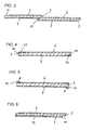
- At least one of the conductive layers 6, 7 is not led to the edge of the seal 3, but only so far that the length and thus the dielectric strength of the air gap between the two loaded with test voltage layers larger is used as the test voltage used for the leak test (cf. Fig. 2 and 3 ).
- At least one of the conductive layers 6, 7 is arranged inside the sealing strip 3, wherein this inner conductive layer 6 is narrower overall than the sealing strip 3 to be tested, so that the conductive layer 6 adjoins the web longitudinal sides is completely enclosed by electrically insulating sealing material and at the longitudinal edges of the geomembrane a sufficiently high dielectric strength with respect to the second conductive layer 7 is achieved for the implementation of the test method (see. Fig. 2 ).
- the conductive layer 6 arranged on the mountain side or on the underside of the seal or sealing membrane 3 is designed as a conductive fleece, the conductive fleece being largely flush on one longitudinal side of the geomembrane 3 up to the edge of the seal 3 is guided, but on the other longitudinal side of the geomembrane to be tested 3 but in width of the welding zone 11 opposite the web edge, so that the web before welding with the adjacent geomembrane 3 does not have to be removed from the welding zone consuming (see. Fig. 3 ).
- the conductive layer 61, 71 arranged in the region 11 of the subsequent welding zone may advantageously consist of an electrically conductive self-adhesive film or an electrically conductive self-adhesive fleece or of an electrically conductive, wipeable or washable coating.
- the conductive layer 6, 7 can also be realized in the region of the welding zone 11 in such a way that the fleece arranged on the back of the sealant is applied in the entire width of the geomembrane 3 to be tested Area of the welding zone 11 has only a low adhesive tensile strength against the geomembrane 3, so that it can be detached after the tightness test and before welding without much effort in the welding zone and then can be brought out of the weld zone 11 by folding or cutting back.
- the folding over of the conductive layer 6 or 7 is in Fig. 5 indicated by arrows.
- the conductivity of at least one of the conductive layers 6, 7 is advantageously adjusted in its areal conductivity to the conductive layer 7 arranged within the seal 3 to be tested or arranged on the accessible visible side of the seal 3 in that, even when the maximum possible test voltage and complete electrical charging of the seal in the event of a short circuit between the conductive layers 6, 7, the maximum possible short-circuit or discharge current is limited by the conductive layer 7 which causes the internal resistance of the charged seal 3 It will be understood that there can be no danger to the test apparatus 5 itself or to life and limb, regardless of where it is sealing it to a contact or approximation to the test under test of Fr. emd emotions or people is coming.
- This conductive layer 7 or both conductive layers 6, 7 preferably has a surface resistance of more than 10 4 ohms and a resistivity of more than 10 3 ohm cm.
- a preferred embodiment of the structural seal according to the invention provides that on the visible side of the inner conductive layer 7, an electrically non-conductive foil or protective layer 12 is arranged, which preferably has a light color.
- At least one of the required electrically conductive layers 6, 7 is formed as a metal foil or metallized plastic film or as a metallic or metallized other fabric, wherein at least one surface is electrically nonconductive.
- a tunnel inner shell 4 the electrical resistance measured, it can be determined according to the invention, whether the reinforcement is applied in a manner to the seal 3, that the seal has already been damaged on the upper side, but without being pierced already, the position of the damage in the already described manner via the measurement of the strand currents or the resistance ratios or the voltage conditions when measured over at least two spaced feed line or at least two spaced measuring points in one of the conductive layers 6, 7 can be limited so that the danger spot recognized before concreting and can be eliminated.
- one of the conductive layers is designed so that it is firmly connected to the testing seal 3 is connected, wherein the conductive layer on at least one. Longitudinal side of the waterproofing sheet 3 to be tested is not brought up to the edge, but is at least as far away from this, that a welding of the sealing strip 3 with its adjacent web 3 is possible without the conductive layer extends into the joining zone 11.
- At least one of the conductive layers 6, 7 is formed so that it reaches as far as the edge of the webs to be joined and thus into the joining zone, wherein it remains in the joining zone 11 during the joining process and during the joining process with the plastic material of the seal 3 which has been softened by joining so that the conductivity of the layer 6, 7 in the joining region is interrupted.
- At least one conductive layer 6, 7 is formed as a peelable film-like layer on the seal 3 to be tested, so that the layer is at least partially removed from the extent required for joining individual sealing sheets 3 Seal 3 can be deducted.
- the above-described conductive layer is also used to check during the concreting operation, e.g. when concreting a tunnel inner shell of the concrete to be concreted annulus is completely filled with concrete or if unfilled areas are present in which at later pressurized water, the tunnel seal is pressed unprotected on the reinforcement of the inner shell.
- the electrical capacitance of one or both conductive layers is measured during the concreting process or thereafter against the introduced concrete and the measured values are compared with a desired value or a comparison value.
- the embodiment or application of the invention is not limited to tunnels. Rather, the inventive method or the inventive Building waterproofing also advantageous in the tightness control of seals of landfills, liquid tanks and / or roofs, in particular flat roofs apply.
Landscapes
- Engineering & Computer Science (AREA)
- Life Sciences & Earth Sciences (AREA)
- Environmental & Geological Engineering (AREA)
- Hydrology & Water Resources (AREA)
- General Life Sciences & Earth Sciences (AREA)
- Mining & Mineral Resources (AREA)
- Paleontology (AREA)
- Civil Engineering (AREA)
- General Engineering & Computer Science (AREA)
- Structural Engineering (AREA)
- Examining Or Testing Airtightness (AREA)
- Investigating Or Analyzing Materials By The Use Of Electric Means (AREA)
Claims (19)
- Procédé pour la détection de points d'endommagements ou de défauts, en particulier de points faibles, présentant une épaisseur de matériau réduite, dans un étanchement d'ouvrage (3), genre membrane, électriquement non conducteur ou seulement faiblement conducteur, qui présente, par rapport à l'air, une résistance diélectrique disruptive élevée et est doté d'une couche électriquement conductrice (6), qui est disposée à l'intérieur ou à l'extérieur de l'étanchement d'ouvrage (3), s'étend sensiblement sur toute la surface de l'étanchement d'ouvrage et sur laquelle est appliquée une tension électrique d'essai, caractérisé en ce que, pour la détection desdits points d'endommagements, de défauts et / ou faibles, est utilisée une autre couche électriquement conductrice (7), qui est électriquement séparée de ladite couche électriquement conductrice (6) par l'étanchement d'ouvrage (3) et qui s'étend sensiblement sur toute la surface de l'étanchement d'ouvrage (3), sachant que l'hauteur de la tension d'essai entre les couches électriquement conductrices (6, 7) soumises à la tension, est choisie de sorte que, lors de la présence d'au moins un point d'endommagement, de défaut et / ou faible et électriquement non conducteur ou seulement faiblement conducteur dans l'étanchement d'ouvrage (3), la résistance diélectrique disruptive soit dépassée et qu'une étincelle électrique ou un arc électrique se produise à l'endroit du point d'endommagement, de défaut et / ou faible, sachant que la tension d'essai est choisie inférieure à une tension d'essai destructive, à laquelle un claquage électrique avec formation d'une étincelle électrique ou d'un arc électrique aurait lieu sur un étanchement d'ouvrage non endommagé et / ou non atténué, correspondant à l'étanchement d'ouvrage (3) à contrôler.
- Procédé selon la revendication 1, caractérisé en ce que la tension d'essai appliquée sur les couches électriquement conductrices est choisie de sorte qu'elle comporte au moins 1000 Volt par millimètre de l'épaisseur de l'étanchement d'ouvrage (3) à contrôler.
- Procédé selon la revendication 1 ou 2, caractérisé en ce que une présence d'étincelles électriques et / ou d'arcs électriques est détectée lors de l'application de la tension d'essai sur les couches conductrices, en saisissant les signaux de perturbation électromagnétiques provenant de l'étincelle électrique et / ou du arc électrique, par un détecteur et / ou en saisissant et exploitant les effets lumineux, de radiation thermique et / ou l'échauffement du matériau, provenant de l'étincelle électrique et / ou du arc électrique.
- Procédé selon l'une des revendications 1 à 3, caractérisé en ce que l'hauteur de la tension appliquée sur l'étanchement d'ouvrage à contrôler, par l'intermédiaire des couches conductrices (6, 7), et / ou le flux de courant de la source de tension (8) dans l'une des couches conductrices (6, 7) sont mesurés.
- Procédé selon l'une des revendications 1 à 4, caractérisé en ce que l'étanchement d'ouvrage (3) à contrôler est divisé en sections à contrôler individuelles, en segmentant au moins l'une des couches électriquement conductrices de sorte que, lors de l'application de la tension d'essai sur chacun des segments de la couche conductrice (6, 7) l'application de la tension est limitée à la section à contrôler individuelles associée.
- Procédé selon l'une des revendications 1 à 5, caractérisé en ce qu'une couche de support électriquement conductrice (2) de l'étanchement d'ouvrage (3) est utilisée en tant que l'une des couches électriquement conductrices.
- Procédé selon l'une des revendications 1 à 6, caractérisé en ce qu'au moins la couche électriquement conductrice (7), disposée sur la face accessible de l'étanchement d'ouvrage (3), est pourvue d'une couche électriquement non conductrice (12), de préférence d'une feuille de matière synthétique de couleur claire.
- Procédé selon l'une des revendications 1 à 7, caractérisé en ce que la formation ininterrompue de la couche électriquement conductrice (7), disposée au moins sur la face accessible de l'étanchement d'ouvrage (3), et / ou la formation ininterrompue de la couche électriquement conductrice (6), disposée sur la face arrière de l'étanchement d'ouvrage (3), est contrôlée par mesure de capacité électrique.
- Etanchement d'ouvrage (3) genre membrane en matériau électriquement non conducteur ou seulement faiblement conducteur, qui, par rapport à l'air, présente une résistance diélectrique disruptive élevée, avec un dispositif de contrôle (5), doté d'une source de tension électrique, pour la détection de points d'endommagements ou de défauts, en particulier de points faibles présentant une épaisseur de matériau réduite sur l'étanchement d'ouvrage (3), et avec une couche électriquement conductrice (6), qui est disposée à l'intérieur ou à l'extérieur de l'étanchement d'ouvrage (3) et s'étend sensiblement sur toute la surface de l'étanchement d'ouvrage (3), caractérisé en ce qu'il est prévue une autre couche électriquement conductrice (7), qui est électriquement séparée de ladite couche électriquement conductrice par l'étanchement d'ouvrage (3) et qui s'étend sensiblement sur toute la surface de l'étanchement d'ouvrage (3), sachant que le dispositif de contrôle (5) est doté de moyens de réglage de l'hauteur de la tension d'essai devant être appliquée sur l'étanchement d'ouvrage (3) par l'intermédiaire des couches électriquement conductrices, de sorte que la tension d'essai puisse être élevée, en continu ou pas à pas, de zéro ou d'une valeur minimum supérieure à zéro jusqu'à une valeur de tension, qui, réduite d'un coefficient de sécurité, est située au-dessous d'une tension destructive, à laquelle un claquage électrique avec formation d'une étincelle électrique ou d'un arc électrique aurait lieu sur un étanchement d'ouvrage non endommagé et / ou non atténué, correspondant à l'étanchement d'ouvrage à contrôler.
- Etanchement d'ouvrage selon la revendication 9, caractérisé en ce que le détecteur est formé par au moins une caméra, en particulier une caméra à rayonnement thermique.
- Etanchement d'ouvrage selon la revendication 9 ou 10, caractérisé en ce qu'il est divisé en sections à contrôler individuelles par une segmentation d'au moins l'une des couches électriquement conductrices (6, 7).
- Etanchement d'ouvrage selon l'une des revendications 9 à 11, caractérisé en ce que les couches électriquement conductrices (6, 7) et l'étanchement d'ouvrage (3) genre membrane, électriquement non conducteur ou seulement faiblement conducteur sont prévues en forme de système sandwich multicouche préfabriqué, sachant que les couches électriquement conductrices (6, 7) sont reliées à l'étanchement d'ouvrage (3) qui les séparent électriquement par fusion de matériau et / ou par emboîtement.
- Etanchement d'ouvrage selon l'une des revendications 9 à 12, caractérisé en ce que les couches électriquement conductrices (6, 7) présentent une résistance de surface inférieure à 106 Ohm et / ou une résistance électrique spécifique inférieure à 105 Ohm / cm.
- Etanchement d'ouvrage selon l'une des revendications 9 à 13, caractérisé en ce qu'au moins une des couches électriquement conductrices (6, 7) consiste en un non-tissé, un tissu à mailles ou toute autre structure surfacique en matériau non conducteur de lui-même, sachant que le non-tissé ou la structure surfacique est pourvu/e d'une matière hygroscopique.
- Etanchement d'ouvrage selon l'une des revendications 9 à 14, caractérisé en ce qu'au moins une des couches électriquement conductrices (6, 7) est disposée à l'intérieur d'une bande d'étanchéité en matière synthétique, à partir de laquelle l'étanchement d'ouvrage (3) est formé, sachant que cette couche électriquement conductrice (6) est globalement plus étroite que la bande d'étanchéité en matière synthétique, de sorte que, sur les côtés longitudinaux de la bande d'étanchéité en matière synthétique, la couche électriquement conductrice (6) se trouve complètement enveloppée de matériau d'étanchéité électriquement isolant.
- Etanchement d'ouvrage selon l'une des revendications 9 à 15, caractérisé en ce que celui-ci est formé par des bandes d'étanchéité en matière synthétiques, qui peuvent être soudées ensemble, sachant que l'une des couches électriquement conductrices (6, 7) est reliée avec le dos de la bande d'étanchéité en matière synthétique respective, cette couche conductrice, disposée à l'arrière, se raccordant à fleur ou presque à fleur au bord longitudinal de la bande d'étanchéité en matière synthétique et se terminant, par rapport à l'autre bord longitudinal de la bande d'étanchéité en matière plastique, avec un décalage, dont la largeur définit un bord de joint (11), et sachant que le bord de joint (11) arrière est pourvu d'une couche marginale électriquement conductrice (61, 71), pouvant être enlevée facilement, qui est reliée électriquement à la couche conductrice (6, 7), disposée à l'arrière.
- Etanchement d'ouvrage selon l'une des revendications 9 à 16, caractérisé en ce qu'au moins une des couches électriquement conductrices (6, 7), en particulier la couche conductrice (7) disposée sur la face visible et accessible de l'étanchement d'ouvrage (3), présente une conductibilité en surface, qui est réglée de sorte que le courant maximal de court-circuit ou de décharge, circulant entre les couches électriquement conductrices en cas de court-circuit, même lors de l'application de la tension d'essai la plus élevée que possible et d'un chargement électrique complète de l'étanchement d'ouvrage, soit limité à une valeur non dangereuse pour la vie.
- Etanchement d'ouvrage selon la revendication 17, caractérisé en ce que celle-ci ou les deux couches électriquement conductrices (6, 7) présentent une résistance de surface supérieure à 104 Ohm et / ou une résistance électrique spécifique supérieure à 103 Ohm / cm.
- Etanchement d'ouvrage selon l'une des revendications 9 à 18, caractérisé en ce qu'au moins une des couches électriquement conductrices (6, 7) est formée par une feuille métallique, une feuille de matière synthétique métallisée, une feuille de matière synthétique, dont la conductibilité est ajustée par des matières additives accroissant la conductibilité, une feuille de matière synthétique conductrice, fabriquée en matières synthétiques conductrices intrinsèques, une structure surfacique métallique ou une structure surfacique métallisée, sachant que sa face opposée à l'étanchement d'ouvrage (3) n'est pas électriquement conductrice et / ou est pourvue d'une couche électriquement non conductrice (12).
Applications Claiming Priority (2)
| Application Number | Priority Date | Filing Date | Title |
|---|---|---|---|
| DE102008033947A DE102008033947A1 (de) | 2008-07-19 | 2008-07-19 | Verfahren und Vorrichtung zur Dichtheitsprüfung von Bauwerksabdichtungen |
| PCT/EP2009/059322 WO2010010072A1 (fr) | 2008-07-19 | 2009-07-20 | Procédé et dispositif pour essais d'étanchéité sur étanchements d'ouvrages |
Publications (2)
| Publication Number | Publication Date |
|---|---|
| EP2310577A1 EP2310577A1 (fr) | 2011-04-20 |
| EP2310577B1 true EP2310577B1 (fr) | 2012-11-07 |
Family
ID=41057544
Family Applications (1)
| Application Number | Title | Priority Date | Filing Date |
|---|---|---|---|
| EP09780849A Not-in-force EP2310577B1 (fr) | 2008-07-19 | 2009-07-20 | Procédé et dispositif pour essais d'étanchéité sur étanchements d'ouvrages |
Country Status (10)
| Country | Link |
|---|---|
| US (1) | US8604799B2 (fr) |
| EP (1) | EP2310577B1 (fr) |
| JP (1) | JP5307890B2 (fr) |
| KR (1) | KR20110040944A (fr) |
| CN (1) | CN102099531B (fr) |
| AU (1) | AU2009273292B2 (fr) |
| CA (1) | CA2731369C (fr) |
| DE (1) | DE102008033947A1 (fr) |
| ES (1) | ES2398947T3 (fr) |
| WO (1) | WO2010010072A1 (fr) |
Families Citing this family (26)
| Publication number | Priority date | Publication date | Assignee | Title |
|---|---|---|---|---|
| US20140114590A1 (en) * | 2012-10-23 | 2014-04-24 | Clark Robert Gunness | Leak detection and location system and method |
| DE102013110928B4 (de) | 2013-09-13 | 2015-06-03 | Dätwyler Sealing Technologies Deutschland Gmbh | Prüfvorrichtung zur Prüfung von Dichtungen mit Verankerungsfüßen sowie deren Verwendung |
| CN105464150B (zh) * | 2015-12-21 | 2018-03-13 | 中交天津港湾工程研究院有限公司 | 一种真空预压密封墙工作效能的监测方法 |
| KR20180102549A (ko) * | 2016-01-27 | 2018-09-17 | 크리스탑스 드라우딩스 | 전기 도전성 다층 재료 |
| US10408599B2 (en) * | 2016-03-18 | 2019-09-10 | Jiaotu Co., Ltd. | Sensing circuit, processing method of sensing circuit and curved surface profile measuring method thereof |
| JP6967242B2 (ja) | 2016-07-25 | 2021-11-17 | 国立大学法人大阪大学 | シート状システム、及び構造物運用支援システム |
| WO2018096389A1 (fr) * | 2016-11-25 | 2018-05-31 | Draudins Kristaps | Matériau multicouches conducteur pour application de détection de fuites |
| CN106761809A (zh) * | 2016-12-19 | 2017-05-31 | 中国电建集团中南勘测设计研究院有限公司 | 一种可进行缺陷检测、监测的地下岩洞储气库结构 |
| CN106759268B (zh) * | 2017-02-27 | 2018-08-31 | 济南轨道交通集团有限公司 | 深层地铁车站维护结构渗流通道装置及方法 |
| CN109838871A (zh) * | 2017-11-28 | 2019-06-04 | 山西彩云归科技有限公司 | 检测房间密闭性的方法和新风系统 |
| US10809052B1 (en) * | 2018-09-19 | 2020-10-20 | Onevision Corporation | System for measuring crimped container seams |
| US10488293B1 (en) * | 2018-10-10 | 2019-11-26 | Layfield Group Ltd. | Conductive geotextile |
| CN109616004B (zh) * | 2018-12-28 | 2024-04-05 | 中交上海三航科学研究院有限公司 | 水下隧道结构模型及其制作方法和测试方法 |
| RU2720344C1 (ru) * | 2019-08-29 | 2020-04-29 | Общество с ограниченной ответственностью "К-СИСТЕМС ГРУПП" | Способ потоковой инструментальной диагностики герметичности сухого гидроизоляционного слоя кровли |
| CN111707965B (zh) * | 2020-05-26 | 2022-08-09 | 欣旺达电动汽车电池有限公司 | 锂离子电池短路测试的方法 |
| CN111883942B (zh) * | 2020-07-13 | 2022-10-11 | 中国人民解放军63653部队 | 一种高阻岩洞室内的全断面组合接地方法 |
| EP4240924B1 (fr) | 2020-11-06 | 2025-01-29 | Watts Regulator Co. | Systèmes de drain de toit intelligent |
| US12012759B2 (en) | 2020-11-06 | 2024-06-18 | Watts Regulator Co. | Intelligent roof drain systems and methods |
| CN113008490B (zh) * | 2021-02-02 | 2022-03-15 | 清华大学 | 一种泄漏自检测橡胶密封件、制备方法及泄漏检测方法 |
| CN114887912B (zh) * | 2022-05-05 | 2024-01-09 | 湖南金凯循环科技股份有限公司 | 一种具有漏电检测合格品输出功能的锂电池盖板测试装置 |
| CN115165264A (zh) * | 2022-07-15 | 2022-10-11 | 山东省医疗器械和药品包装检验研究院 | 一种混悬液密封完整性的测试方法及测试装置 |
| CN117129559A (zh) * | 2023-10-24 | 2023-11-28 | 宁德时代新能源科技股份有限公司 | 检测装置及检测方法 |
| CN117949150B (zh) * | 2024-03-26 | 2024-06-04 | 中铁城建集团第一工程有限公司 | 一种用于预制板密封胶的检测装置 |
| CN118857593B (zh) * | 2024-09-24 | 2025-01-14 | 河北凯威信达信息技术有限公司 | 一种x射线管测试设备 |
| CN119618519B (zh) * | 2025-02-12 | 2025-04-11 | 四川鑫中泰新材料有限公司 | 基于电火花检测装置的钢塑复合管密封检测方法、装置、处理器及存储介质 |
| CN120844638B (zh) * | 2025-09-22 | 2025-12-23 | 长安大学 | 一种水下深基坑变形监测系统及监测方法 |
Family Cites Families (16)
| Publication number | Priority date | Publication date | Assignee | Title |
|---|---|---|---|---|
| US4302725A (en) * | 1980-03-28 | 1981-11-24 | Rca Corporation | Method for testing panel-to-funnel sealing layer of a cathode-ray tube |
| DE4125430C2 (de) * | 1991-08-01 | 1997-01-30 | Frank Deponietechnik Gmbh | Anordnung auf Dichtigkeit kontrollierbarer Dichtungsbahnen aus Kunststoff, insbesondere für Deponien |
| JP2981343B2 (ja) * | 1992-08-17 | 1999-11-22 | 株式会社大林組 | 遮水シート及び遮水シートの破損部検出方法 |
| US5288168A (en) * | 1992-08-24 | 1994-02-22 | Gundle Lining Construction Corporation | Method and apparatus for lining outdoor fluid containment areas to facilitate electrical leak detection |
| US6004070A (en) | 1996-07-08 | 1999-12-21 | Van Camp; John W. | Waste storage containment cell, method of operating, and apparatus therefore |
| JP3137591B2 (ja) * | 1996-12-04 | 2001-02-26 | 太陽工業株式会社 | 導電層を有するシートの接合部の検査方法 |
| JP4057139B2 (ja) * | 1998-04-16 | 2008-03-05 | 日本テトラパック株式会社 | 損傷検出装置 |
| JP2000005717A (ja) * | 1998-06-19 | 2000-01-11 | Toyo Tire & Rubber Co Ltd | 遮水シートの探傷方法および敷設構造 |
| WO2000001895A1 (fr) | 1998-07-07 | 2000-01-13 | Gse Lining Technology, Inc. | Geomembrane multicouche electroconductrice |
| US6648552B1 (en) * | 1999-10-14 | 2003-11-18 | Bechtel Bwxt Idaho, Llc | Sensor system for buried waste containment sites |
| DE10063833A1 (de) * | 2000-12-21 | 2002-07-11 | Boehringer Ingelheim Int | Verfahren und Vorrichtung zum Prüfen von Mehrschichtfolien und daraus hergestellten Behältern |
| JP3682917B2 (ja) * | 2001-06-26 | 2005-08-17 | 株式会社西村測量設計事務所 | 遮水シート接合不良検知方法及び検知器 |
| JP4336504B2 (ja) * | 2003-02-06 | 2009-09-30 | 株式会社大林組 | 遮水シートにおける接合部試験方法 |
| CN2707834Y (zh) * | 2004-05-20 | 2005-07-06 | 楼龙春 | 用于海上钢桩的阴极保护装置 |
| GB2420313B (en) * | 2004-11-17 | 2009-04-29 | Drc Polymer Products Ltd | Geomembrane |
| CN101173911A (zh) * | 2007-10-17 | 2008-05-07 | 中国人民解放军海军工程大学 | 一种管道缺陷快速扫查方法和无损检测装置 |
-
2008
- 2008-07-19 DE DE102008033947A patent/DE102008033947A1/de not_active Withdrawn
-
2009
- 2009-07-20 WO PCT/EP2009/059322 patent/WO2010010072A1/fr not_active Ceased
- 2009-07-20 EP EP09780849A patent/EP2310577B1/fr not_active Not-in-force
- 2009-07-20 AU AU2009273292A patent/AU2009273292B2/en not_active Ceased
- 2009-07-20 US US13/054,852 patent/US8604799B2/en not_active Expired - Fee Related
- 2009-07-20 KR KR1020117003992A patent/KR20110040944A/ko not_active Ceased
- 2009-07-20 CN CN200980128345.2A patent/CN102099531B/zh not_active Expired - Fee Related
- 2009-07-20 JP JP2011517960A patent/JP5307890B2/ja not_active Expired - Fee Related
- 2009-07-20 CA CA2731369A patent/CA2731369C/fr not_active Expired - Fee Related
- 2009-07-20 ES ES09780849T patent/ES2398947T3/es active Active
Also Published As
| Publication number | Publication date |
|---|---|
| EP2310577A1 (fr) | 2011-04-20 |
| US20110187394A1 (en) | 2011-08-04 |
| ES2398947T3 (es) | 2013-03-22 |
| DE102008033947A1 (de) | 2010-01-21 |
| CN102099531A (zh) | 2011-06-15 |
| CA2731369A1 (fr) | 2010-01-28 |
| US8604799B2 (en) | 2013-12-10 |
| JP5307890B2 (ja) | 2013-10-02 |
| WO2010010072A1 (fr) | 2010-01-28 |
| AU2009273292B2 (en) | 2013-10-24 |
| AU2009273292A1 (en) | 2010-01-28 |
| JP2011528758A (ja) | 2011-11-24 |
| CA2731369C (fr) | 2016-09-20 |
| KR20110040944A (ko) | 2011-04-20 |
| CN102099531B (zh) | 2014-04-09 |
Similar Documents
| Publication | Publication Date | Title |
|---|---|---|
| EP2310577B1 (fr) | Procédé et dispositif pour essais d'étanchéité sur étanchements d'ouvrages | |
| EP1875189B1 (fr) | Dispositif de détection et de localisation de fuites pour des toits plats ou analogues | |
| DE4125430C2 (de) | Anordnung auf Dichtigkeit kontrollierbarer Dichtungsbahnen aus Kunststoff, insbesondere für Deponien | |
| DE69301212T2 (de) | Verfahren und Vorrichtung zur Auskleidung von Flüssigkeit enthaltenden Freibecken | |
| EP3069129B1 (fr) | Système et procédé de surveillance d'un sous-sol pour déterminer ses dommages et/ou pour la protection d'un sous-sol contre des dommages | |
| DE3620976C2 (de) | Chemisch beständiger, flüssigkeitsdichter Belag für Auffangräume, Behälter oder dergleichen aus Beton | |
| EP0456094B1 (fr) | Réservoir à fond plat | |
| WO2006089629A1 (fr) | Conduite collectrice destinee au controle et a la localisation de fuites | |
| EP2612549A2 (fr) | Système d'étanchéification pour surfaces intérieures de parois latérales en béton de silos, silo doté de celui-ci, procédé de fabrication du système d'étanchéification et procédé de surveillance de l'état d'étanchéité d'un tel silo | |
| DE19841317C1 (de) | Leckanzeigeeinrichtung für Kunststoffabdichtungen sowie entsprechendes Verfahren zur Leckanzeige | |
| DE8902256U1 (de) | Prüfeinrichtung für eine Abdichtung für Ingenieurbauten | |
| EP2488361B1 (fr) | Procédé de production d'un assemblage d'étanchéité multicouche ayant une couche centrale électriquement conductrice utilisant des bandes bitumineuses soudables et bandes bitumineuses soudables pour un tel assemblage d'étanchéité | |
| DE3417332C2 (de) | Anordnung zum Erkennen von Undichtigkeiten oder Lecks von Deponien | |
| DE10036362C2 (de) | Verfahren und System zur Erkennung und Ortung von Leckagen in Abdichtungen, insbesondere Bauwerksabdichtungen | |
| EP0307615A2 (fr) | Dispositif pour la détermination non destructive de dégâts dans la couverture de ponts, réservoirs et toits plats | |
| DE4137108A1 (de) | Vorrichtung zum ueberwachen der dichtheit von im freien und im erdreich verlegten rohrleitungen und bauwerken aus thermoplastischem kunststoff | |
| EP3933137B1 (fr) | Natte destinée à la création d'un capteur de localisation de fuite, capteur, appareil de surveillance, zone de construction et procédé de fabrication et d'utilisation d'un tel capteur | |
| DE19638733C1 (de) | Verfahren und Vorrichtung zur Überwachung von Kunststoffabdichtungen auf Beschädigung während des Überbauens oder Überschüttens | |
| WO1994012736A1 (fr) | Electrode de mesure pour systemes de localisation de fuites | |
| DE2442058C2 (de) | Ausbau für unterirdische Räume, insbesondere im Tunnel- und im Untertagebergbau und Verfahren zum Einbringen dieses Ausbaus | |
| CH696087A5 (de) | System und Verfahren zur Überprüfung eines Substrats auf Feuchtigkeitseinbrüche. | |
| DE102004005375A1 (de) | Verfahren zur Herstellung dichter Schichten, dichte Schicht und Verfahren zur Überwachung der Dichtheit derselben | |
| DE9117099U1 (de) | Abdichtungsfolie mit einer elektrischen Meßeinrichtung zur Erfassung von Lecks in der Folie | |
| DE20301010U1 (de) | Leichtflüssigkeitsabscheider mit Leckanzeige |
Legal Events
| Date | Code | Title | Description |
|---|---|---|---|
| PUAI | Public reference made under article 153(3) epc to a published international application that has entered the european phase |
Free format text: ORIGINAL CODE: 0009012 |
|
| 17P | Request for examination filed |
Effective date: 20110117 |
|
| AK | Designated contracting states |
Kind code of ref document: A1 Designated state(s): AT BE BG CH CY CZ DE DK EE ES FI FR GB GR HR HU IE IS IT LI LT LU LV MC MK MT NL NO PL PT RO SE SI SK SM TR |
|
| AX | Request for extension of the european patent |
Extension state: AL BA RS |
|
| RIN1 | Information on inventor provided before grant (corrected) |
Inventor name: ROEDEL, ANDREAS Inventor name: KOMMA, NORBERT |
|
| DAX | Request for extension of the european patent (deleted) | ||
| GRAP | Despatch of communication of intention to grant a patent |
Free format text: ORIGINAL CODE: EPIDOSNIGR1 |
|
| GRAS | Grant fee paid |
Free format text: ORIGINAL CODE: EPIDOSNIGR3 |
|
| GRAA | (expected) grant |
Free format text: ORIGINAL CODE: 0009210 |
|
| AK | Designated contracting states |
Kind code of ref document: B1 Designated state(s): AT BE BG CH CY CZ DE DK EE ES FI FR GB GR HR HU IE IS IT LI LT LU LV MC MK MT NL NO PL PT RO SE SI SK SM TR |
|
| REG | Reference to a national code |
Ref country code: GB Ref legal event code: FG4D Free format text: NOT ENGLISH |
|
| REG | Reference to a national code |
Ref country code: AT Ref legal event code: REF Ref document number: 583080 Country of ref document: AT Kind code of ref document: T Effective date: 20121115 Ref country code: CH Ref legal event code: EP |
|
| REG | Reference to a national code |
Ref country code: IE Ref legal event code: FG4D Free format text: LANGUAGE OF EP DOCUMENT: GERMAN |
|
| REG | Reference to a national code |
Ref country code: DE Ref legal event code: R096 Ref document number: 502009005334 Country of ref document: DE Effective date: 20130103 |
|
| REG | Reference to a national code |
Ref country code: CH Ref legal event code: NV Representative=s name: TROESCH SCHEIDEGGER WERNER AG, CH |
|
| REG | Reference to a national code |
Ref country code: CH Ref legal event code: NV Representative=s name: TROESCH SCHEIDEGGER WERNER AG, CH |
|
| REG | Reference to a national code |
Ref country code: ES Ref legal event code: FG2A Ref document number: 2398947 Country of ref document: ES Kind code of ref document: T3 Effective date: 20130322 |
|
| REG | Reference to a national code |
Ref country code: NL Ref legal event code: VDEP Effective date: 20121107 |
|
| REG | Reference to a national code |
Ref country code: LT Ref legal event code: MG4D |
|
| PG25 | Lapsed in a contracting state [announced via postgrant information from national office to epo] |
Ref country code: NL Free format text: LAPSE BECAUSE OF FAILURE TO SUBMIT A TRANSLATION OF THE DESCRIPTION OR TO PAY THE FEE WITHIN THE PRESCRIBED TIME-LIMIT Effective date: 20121107 Ref country code: IS Free format text: LAPSE BECAUSE OF FAILURE TO SUBMIT A TRANSLATION OF THE DESCRIPTION OR TO PAY THE FEE WITHIN THE PRESCRIBED TIME-LIMIT Effective date: 20130307 Ref country code: HR Free format text: LAPSE BECAUSE OF FAILURE TO SUBMIT A TRANSLATION OF THE DESCRIPTION OR TO PAY THE FEE WITHIN THE PRESCRIBED TIME-LIMIT Effective date: 20121107 Ref country code: LT Free format text: LAPSE BECAUSE OF FAILURE TO SUBMIT A TRANSLATION OF THE DESCRIPTION OR TO PAY THE FEE WITHIN THE PRESCRIBED TIME-LIMIT Effective date: 20121107 Ref country code: SE Free format text: LAPSE BECAUSE OF FAILURE TO SUBMIT A TRANSLATION OF THE DESCRIPTION OR TO PAY THE FEE WITHIN THE PRESCRIBED TIME-LIMIT Effective date: 20121107 Ref country code: NO Free format text: LAPSE BECAUSE OF FAILURE TO SUBMIT A TRANSLATION OF THE DESCRIPTION OR TO PAY THE FEE WITHIN THE PRESCRIBED TIME-LIMIT Effective date: 20130207 Ref country code: FI Free format text: LAPSE BECAUSE OF FAILURE TO SUBMIT A TRANSLATION OF THE DESCRIPTION OR TO PAY THE FEE WITHIN THE PRESCRIBED TIME-LIMIT Effective date: 20121107 |
|
| PG25 | Lapsed in a contracting state [announced via postgrant information from national office to epo] |
Ref country code: SI Free format text: LAPSE BECAUSE OF FAILURE TO SUBMIT A TRANSLATION OF THE DESCRIPTION OR TO PAY THE FEE WITHIN THE PRESCRIBED TIME-LIMIT Effective date: 20121107 Ref country code: PL Free format text: LAPSE BECAUSE OF FAILURE TO SUBMIT A TRANSLATION OF THE DESCRIPTION OR TO PAY THE FEE WITHIN THE PRESCRIBED TIME-LIMIT Effective date: 20121107 Ref country code: LV Free format text: LAPSE BECAUSE OF FAILURE TO SUBMIT A TRANSLATION OF THE DESCRIPTION OR TO PAY THE FEE WITHIN THE PRESCRIBED TIME-LIMIT Effective date: 20121107 Ref country code: PT Free format text: LAPSE BECAUSE OF FAILURE TO SUBMIT A TRANSLATION OF THE DESCRIPTION OR TO PAY THE FEE WITHIN THE PRESCRIBED TIME-LIMIT Effective date: 20130307 Ref country code: GR Free format text: LAPSE BECAUSE OF FAILURE TO SUBMIT A TRANSLATION OF THE DESCRIPTION OR TO PAY THE FEE WITHIN THE PRESCRIBED TIME-LIMIT Effective date: 20130208 |
|
| PG25 | Lapsed in a contracting state [announced via postgrant information from national office to epo] |
Ref country code: SK Free format text: LAPSE BECAUSE OF FAILURE TO SUBMIT A TRANSLATION OF THE DESCRIPTION OR TO PAY THE FEE WITHIN THE PRESCRIBED TIME-LIMIT Effective date: 20121107 Ref country code: EE Free format text: LAPSE BECAUSE OF FAILURE TO SUBMIT A TRANSLATION OF THE DESCRIPTION OR TO PAY THE FEE WITHIN THE PRESCRIBED TIME-LIMIT Effective date: 20121107 Ref country code: CZ Free format text: LAPSE BECAUSE OF FAILURE TO SUBMIT A TRANSLATION OF THE DESCRIPTION OR TO PAY THE FEE WITHIN THE PRESCRIBED TIME-LIMIT Effective date: 20121107 Ref country code: DK Free format text: LAPSE BECAUSE OF FAILURE TO SUBMIT A TRANSLATION OF THE DESCRIPTION OR TO PAY THE FEE WITHIN THE PRESCRIBED TIME-LIMIT Effective date: 20121107 Ref country code: BG Free format text: LAPSE BECAUSE OF FAILURE TO SUBMIT A TRANSLATION OF THE DESCRIPTION OR TO PAY THE FEE WITHIN THE PRESCRIBED TIME-LIMIT Effective date: 20130207 |
|
| PG25 | Lapsed in a contracting state [announced via postgrant information from national office to epo] |
Ref country code: RO Free format text: LAPSE BECAUSE OF FAILURE TO SUBMIT A TRANSLATION OF THE DESCRIPTION OR TO PAY THE FEE WITHIN THE PRESCRIBED TIME-LIMIT Effective date: 20121107 |
|
| PLBE | No opposition filed within time limit |
Free format text: ORIGINAL CODE: 0009261 |
|
| STAA | Information on the status of an ep patent application or granted ep patent |
Free format text: STATUS: NO OPPOSITION FILED WITHIN TIME LIMIT |
|
| 26N | No opposition filed |
Effective date: 20130808 |
|
| PG25 | Lapsed in a contracting state [announced via postgrant information from national office to epo] |
Ref country code: CY Free format text: LAPSE BECAUSE OF FAILURE TO SUBMIT A TRANSLATION OF THE DESCRIPTION OR TO PAY THE FEE WITHIN THE PRESCRIBED TIME-LIMIT Effective date: 20121107 |
|
| REG | Reference to a national code |
Ref country code: DE Ref legal event code: R097 Ref document number: 502009005334 Country of ref document: DE Effective date: 20130808 |
|
| BERE | Be: lapsed |
Owner name: PROGEO MONITORING G.M.B.H. Effective date: 20130731 |
|
| PG25 | Lapsed in a contracting state [announced via postgrant information from national office to epo] |
Ref country code: MC Free format text: LAPSE BECAUSE OF FAILURE TO SUBMIT A TRANSLATION OF THE DESCRIPTION OR TO PAY THE FEE WITHIN THE PRESCRIBED TIME-LIMIT Effective date: 20121107 |
|
| REG | Reference to a national code |
Ref country code: IE Ref legal event code: MM4A |
|
| PG25 | Lapsed in a contracting state [announced via postgrant information from national office to epo] |
Ref country code: BE Free format text: LAPSE BECAUSE OF NON-PAYMENT OF DUE FEES Effective date: 20130731 |
|
| PG25 | Lapsed in a contracting state [announced via postgrant information from national office to epo] |
Ref country code: IE Free format text: LAPSE BECAUSE OF NON-PAYMENT OF DUE FEES Effective date: 20130720 |
|
| PG25 | Lapsed in a contracting state [announced via postgrant information from national office to epo] |
Ref country code: SM Free format text: LAPSE BECAUSE OF FAILURE TO SUBMIT A TRANSLATION OF THE DESCRIPTION OR TO PAY THE FEE WITHIN THE PRESCRIBED TIME-LIMIT Effective date: 20121107 |
|
| PG25 | Lapsed in a contracting state [announced via postgrant information from national office to epo] |
Ref country code: TR Free format text: LAPSE BECAUSE OF FAILURE TO SUBMIT A TRANSLATION OF THE DESCRIPTION OR TO PAY THE FEE WITHIN THE PRESCRIBED TIME-LIMIT Effective date: 20121107 Ref country code: MT Free format text: LAPSE BECAUSE OF FAILURE TO SUBMIT A TRANSLATION OF THE DESCRIPTION OR TO PAY THE FEE WITHIN THE PRESCRIBED TIME-LIMIT Effective date: 20121107 |
|
| PG25 | Lapsed in a contracting state [announced via postgrant information from national office to epo] |
Ref country code: HU Free format text: LAPSE BECAUSE OF FAILURE TO SUBMIT A TRANSLATION OF THE DESCRIPTION OR TO PAY THE FEE WITHIN THE PRESCRIBED TIME-LIMIT; INVALID AB INITIO Effective date: 20090720 Ref country code: LU Free format text: LAPSE BECAUSE OF NON-PAYMENT OF DUE FEES Effective date: 20130720 Ref country code: MK Free format text: LAPSE BECAUSE OF FAILURE TO SUBMIT A TRANSLATION OF THE DESCRIPTION OR TO PAY THE FEE WITHIN THE PRESCRIBED TIME-LIMIT Effective date: 20121107 |
|
| REG | Reference to a national code |
Ref country code: FR Ref legal event code: PLFP Year of fee payment: 8 |
|
| REG | Reference to a national code |
Ref country code: FR Ref legal event code: PLFP Year of fee payment: 9 |
|
| PGFP | Annual fee paid to national office [announced via postgrant information from national office to epo] |
Ref country code: CH Payment date: 20170823 Year of fee payment: 9 Ref country code: FR Payment date: 20170824 Year of fee payment: 9 Ref country code: DE Payment date: 20170822 Year of fee payment: 9 Ref country code: ES Payment date: 20170823 Year of fee payment: 9 Ref country code: IT Payment date: 20170825 Year of fee payment: 9 Ref country code: GB Payment date: 20170822 Year of fee payment: 9 |
|
| PGFP | Annual fee paid to national office [announced via postgrant information from national office to epo] |
Ref country code: AT Payment date: 20170823 Year of fee payment: 9 |
|
| REG | Reference to a national code |
Ref country code: DE Ref legal event code: R119 Ref document number: 502009005334 Country of ref document: DE |
|
| REG | Reference to a national code |
Ref country code: CH Ref legal event code: PL |
|
| REG | Reference to a national code |
Ref country code: AT Ref legal event code: MM01 Ref document number: 583080 Country of ref document: AT Kind code of ref document: T Effective date: 20180720 |
|
| GBPC | Gb: european patent ceased through non-payment of renewal fee |
Effective date: 20180720 |
|
| PG25 | Lapsed in a contracting state [announced via postgrant information from national office to epo] |
Ref country code: AT Free format text: LAPSE BECAUSE OF NON-PAYMENT OF DUE FEES Effective date: 20180720 Ref country code: GB Free format text: LAPSE BECAUSE OF NON-PAYMENT OF DUE FEES Effective date: 20180720 Ref country code: DE Free format text: LAPSE BECAUSE OF NON-PAYMENT OF DUE FEES Effective date: 20190201 Ref country code: CH Free format text: LAPSE BECAUSE OF NON-PAYMENT OF DUE FEES Effective date: 20180731 Ref country code: LI Free format text: LAPSE BECAUSE OF NON-PAYMENT OF DUE FEES Effective date: 20180731 Ref country code: FR Free format text: LAPSE BECAUSE OF NON-PAYMENT OF DUE FEES Effective date: 20180731 |
|
| PG25 | Lapsed in a contracting state [announced via postgrant information from national office to epo] |
Ref country code: IT Free format text: LAPSE BECAUSE OF NON-PAYMENT OF DUE FEES Effective date: 20180720 |
|
| REG | Reference to a national code |
Ref country code: ES Ref legal event code: FD2A Effective date: 20190917 |
|
| PG25 | Lapsed in a contracting state [announced via postgrant information from national office to epo] |
Ref country code: ES Free format text: LAPSE BECAUSE OF NON-PAYMENT OF DUE FEES Effective date: 20180721 |