EP2311680B1 - Antriebseinheit für ein Hybridfahrzeug - Google Patents
Antriebseinheit für ein Hybridfahrzeug Download PDFInfo
- Publication number
- EP2311680B1 EP2311680B1 EP10186961.8A EP10186961A EP2311680B1 EP 2311680 B1 EP2311680 B1 EP 2311680B1 EP 10186961 A EP10186961 A EP 10186961A EP 2311680 B1 EP2311680 B1 EP 2311680B1
- Authority
- EP
- European Patent Office
- Prior art keywords
- drive unit
- clutch
- disposed
- gearbox
- unit according
- Prior art date
- Legal status (The legal status is an assumption and is not a legal conclusion. Google has not performed a legal analysis and makes no representation as to the accuracy of the status listed.)
- Active
Links
Images

Classifications
-
- B—PERFORMING OPERATIONS; TRANSPORTING
- B60—VEHICLES IN GENERAL
- B60K—ARRANGEMENT OR MOUNTING OF PROPULSION UNITS OR OF TRANSMISSIONS IN VEHICLES; ARRANGEMENT OR MOUNTING OF PLURAL DIVERSE PRIME-MOVERS IN VEHICLES; AUXILIARY DRIVES FOR VEHICLES; INSTRUMENTATION OR DASHBOARDS FOR VEHICLES; ARRANGEMENTS IN CONNECTION WITH COOLING, AIR INTAKE, GAS EXHAUST OR FUEL SUPPLY OF PROPULSION UNITS IN VEHICLES
- B60K6/00—Arrangement or mounting of plural diverse prime-movers for mutual or common propulsion, e.g. hybrid propulsion systems comprising electric motors and internal combustion engines
- B60K6/20—Arrangement or mounting of plural diverse prime-movers for mutual or common propulsion, e.g. hybrid propulsion systems comprising electric motors and internal combustion engines the prime-movers consisting of electric motors and internal combustion engines, e.g. HEVs
- B60K6/42—Arrangement or mounting of plural diverse prime-movers for mutual or common propulsion, e.g. hybrid propulsion systems comprising electric motors and internal combustion engines the prime-movers consisting of electric motors and internal combustion engines, e.g. HEVs characterised by the architecture of the hybrid electric vehicle
- B60K6/48—Parallel type
-
- B—PERFORMING OPERATIONS; TRANSPORTING
- B60—VEHICLES IN GENERAL
- B60K—ARRANGEMENT OR MOUNTING OF PROPULSION UNITS OR OF TRANSMISSIONS IN VEHICLES; ARRANGEMENT OR MOUNTING OF PLURAL DIVERSE PRIME-MOVERS IN VEHICLES; AUXILIARY DRIVES FOR VEHICLES; INSTRUMENTATION OR DASHBOARDS FOR VEHICLES; ARRANGEMENTS IN CONNECTION WITH COOLING, AIR INTAKE, GAS EXHAUST OR FUEL SUPPLY OF PROPULSION UNITS IN VEHICLES
- B60K6/00—Arrangement or mounting of plural diverse prime-movers for mutual or common propulsion, e.g. hybrid propulsion systems comprising electric motors and internal combustion engines
- B60K6/20—Arrangement or mounting of plural diverse prime-movers for mutual or common propulsion, e.g. hybrid propulsion systems comprising electric motors and internal combustion engines the prime-movers consisting of electric motors and internal combustion engines, e.g. HEVs
- B60K6/22—Arrangement or mounting of plural diverse prime-movers for mutual or common propulsion, e.g. hybrid propulsion systems comprising electric motors and internal combustion engines the prime-movers consisting of electric motors and internal combustion engines, e.g. HEVs characterised by apparatus, components or means specially adapted for HEVs
- B60K6/40—Arrangement or mounting of plural diverse prime-movers for mutual or common propulsion, e.g. hybrid propulsion systems comprising electric motors and internal combustion engines the prime-movers consisting of electric motors and internal combustion engines, e.g. HEVs characterised by apparatus, components or means specially adapted for HEVs characterised by the assembly or relative disposition of components
-
- B—PERFORMING OPERATIONS; TRANSPORTING
- B60—VEHICLES IN GENERAL
- B60K—ARRANGEMENT OR MOUNTING OF PROPULSION UNITS OR OF TRANSMISSIONS IN VEHICLES; ARRANGEMENT OR MOUNTING OF PLURAL DIVERSE PRIME-MOVERS IN VEHICLES; AUXILIARY DRIVES FOR VEHICLES; INSTRUMENTATION OR DASHBOARDS FOR VEHICLES; ARRANGEMENTS IN CONNECTION WITH COOLING, AIR INTAKE, GAS EXHAUST OR FUEL SUPPLY OF PROPULSION UNITS IN VEHICLES
- B60K6/00—Arrangement or mounting of plural diverse prime-movers for mutual or common propulsion, e.g. hybrid propulsion systems comprising electric motors and internal combustion engines
- B60K6/20—Arrangement or mounting of plural diverse prime-movers for mutual or common propulsion, e.g. hybrid propulsion systems comprising electric motors and internal combustion engines the prime-movers consisting of electric motors and internal combustion engines, e.g. HEVs
- B60K6/42—Arrangement or mounting of plural diverse prime-movers for mutual or common propulsion, e.g. hybrid propulsion systems comprising electric motors and internal combustion engines the prime-movers consisting of electric motors and internal combustion engines, e.g. HEVs characterised by the architecture of the hybrid electric vehicle
- B60K6/48—Parallel type
- B60K2006/4825—Electric machine connected or connectable to gearbox input shaft
-
- B—PERFORMING OPERATIONS; TRANSPORTING
- B60—VEHICLES IN GENERAL
- B60Y—INDEXING SCHEME RELATING TO ASPECTS CROSS-CUTTING VEHICLE TECHNOLOGY
- B60Y2400/00—Special features of vehicle units
- B60Y2400/42—Clutches or brakes
- B60Y2400/424—Friction clutches
- B60Y2400/4244—Friction clutches of wet type, e.g. using multiple lamellae
-
- B—PERFORMING OPERATIONS; TRANSPORTING
- B60—VEHICLES IN GENERAL
- B60Y—INDEXING SCHEME RELATING TO ASPECTS CROSS-CUTTING VEHICLE TECHNOLOGY
- B60Y2400/00—Special features of vehicle units
- B60Y2400/48—Vibration dampers, e.g. dual mass flywheels
-
- Y—GENERAL TAGGING OF NEW TECHNOLOGICAL DEVELOPMENTS; GENERAL TAGGING OF CROSS-SECTIONAL TECHNOLOGIES SPANNING OVER SEVERAL SECTIONS OF THE IPC; TECHNICAL SUBJECTS COVERED BY FORMER USPC CROSS-REFERENCE ART COLLECTIONS [XRACs] AND DIGESTS
- Y02—TECHNOLOGIES OR APPLICATIONS FOR MITIGATION OR ADAPTATION AGAINST CLIMATE CHANGE
- Y02T—CLIMATE CHANGE MITIGATION TECHNOLOGIES RELATED TO TRANSPORTATION
- Y02T10/00—Road transport of goods or passengers
- Y02T10/60—Other road transportation technologies with climate change mitigation effect
- Y02T10/62—Hybrid vehicles
Definitions
- the invention relates to a drive unit for a hybrid vehicle that can optionally be driven by a combustion engine and / or an electric motor, according to the preamble of claim 1.
- a drive unit for example in the EP 1 736 345 A1 described.
- the present invention is based on the problem of creating an inexpensive, easy-to-assemble and at the same time compact drive unit which is also capable of effectively damping rotational irregularities that occur in a vehicle drive train depending on the respective operating state.
- a drive unit which has an internal combustion engine with an output shaft, a transmission with an input shaft and an electrical machine arranged between the internal combustion engine and the transmission with a Stator and comprising a rotor which can be coupled at least indirectly to the output shaft of the internal combustion engine and to the transmission input shaft for transmitting a torque.
- the drive unit For better decoupling from rotational irregularities occurring in the drive train of the hybrid vehicle, it is proposed to design the drive unit with a first and a second torsion damper, at least the rotor of the electrical machine being arranged within a torque transmission path formed between the torsion dampers.
- the drive unit can further comprise a switchable clutch arranged in the torque transmission path between the internal combustion engine and the transmission, but this can also be arranged outside this torque transmission path, for example between the internal combustion engine and the first torsional damper or within the gear change transmission.
- the torsional damper downstream of the clutch in the torque curve can therefore also be designed to be correspondingly compact.
- the frequency spectrum to be damped can overall be covered more broadly and more effectively.
- the proposed drive unit can thus make a significant contribution to minimizing noise and wear at gear points both outside and inside the transmission.
- the Fig. 1 shows a drive unit 10 with an internal combustion engine 12 as a first drive source with an output shaft designed as a crankshaft 14, the torque of which is introduced into a gear change transmission 26 via a coupling arrangement 16, a first torsion damper 18, a switchable clutch 20 and a second torsion damper 22 via an input shaft 24 can be transferred from there to the drive wheels of a hybrid vehicle via further drive train elements not shown in the drawing here.
- the drive unit 10 also has an electric machine 28 with a stator 30 and a rotor 32 as a second drive source, the torque of which can be introduced into the drive train section formed between the internal combustion engine 12 and the transmission 26.
- the transmission 26 is designed in the present case as a stepped fully automatic transmission.
- a hydrodynamic torque converter is usually connected upstream of such a transmission 26, but this has been omitted in favor of the aforementioned functional elements. It should be emphasized that in the present drive unit 10, only a single, selectively switchable clutch 20 is provided between the internal combustion engine 12 and the transmission 26, which can limit the transmitted torque completely or only to a certain amount for starting as well as for changing gears.
- the coupling arrangement 16 following the crankshaft 14 in the torque path initially comprises an axially flexible torque transmission plate in the form of a Flexplate 34, which is connected radially on the inside by means of screw bolts 36 to the crankshaft 14 and radially on the outside in turn via bolts 38 to a substantially axially rigid transmission disk 40, referred to as a drive plate.
- This connection makes it easy to compensate for axial crankshaft vibrations and any tolerance-related axial mismatch that may arise when the drive unit 10 is assembled. In this way, a mutual undesired tension of the functional elements located in the torque transmission path between the internal combustion engine 12 and the transmission 26 is reliably avoided.
- the driveplate 40 is slightly cranked axially in its radially inner area to create a range of motion and has a hollow hub 40a which is rotationally driven by means of a form-fit connection 42 to a hub 44a of the first torsion damper 18.
- the form-fit connection 42 is designed as an axial form-fit connection, in particular as a Hirth tooth system, in which the two hubs 40a; 44a are axially braced by means of several screw bolts 43.
- bearing 46 Radially within the connected hubs 40a; 44a is an at least partially over both hubs 40a; 44a extending bearing 46, which here represents a roller bearing, designed or arranged, via which the coupling arrangement 16 and the first torsion damper 18 can be supported on the input shaft 24 of the automatic transmission 26 or which provides a bearing point for the transmission input shaft 24.
- the hub 44a facing away from the crankshaft 14 forms at the same time with a disk-shaped one adjoining it and extending essentially radially outward Cover plate 44b and with a further cover plate 44d connected to it by means of rivets 44c, the input part of the first torsion damper 18.
- a plurality of chambers for receiving springs 44e are formed in the circumferential direction, the ends of which are on the one hand on the cover plates 44b; 44d and on the other hand on an annular collar 44f of a hub element 44g which axially between the cover plates 44b; 44d is arranged and that it is rotatably mounted with respect to this over a certain angle of rotation range.
- the hub element 44g has, on the side facing the gearbox 26, a form-fit connection 50 for rotationally driving a driver element 52 which here extends essentially radially and which forms part of an input part 52 of the clutch 20.
- a driver element 52 which here extends essentially radially and which forms part of an input part 52 of the clutch 20.
- tooth profiles provided, the teeth and gaps of which can penetrate each other.
- the tooth profile of the driver element 52 is designed in the form of relatively long tooth fingers and slightly angled in the direction of the corresponding profile, which results in a certain spring effect when joining together, which keeps the active partners in mutual contact essentially without play, but at the same time allows axial and radial compensation.
- the clutch 20 is designed as a wet-running multi-disc clutch, for which purpose the driver element 52 is firmly connected in a radially inner section by means of a rivet connection 54 to a radially externally toothed inner disc carrier 56 on which a plurality of axially displaceable inner discs are arranged, which are in the Interstices of a plurality of outer disks which are axially displaceable on a radially spaced and also toothed outer disk carrier 58 engage and can be brought into a frictional connection with them.
- the driver element 52 is firmly connected in a radially inner section by means of a rivet connection 54 to a radially externally toothed inner disc carrier 56 on which a plurality of axially displaceable inner discs are arranged, which are in the Interstices of a plurality of outer disks which are axially displaceable on a radially spaced and also toothed outer disk carrier 58 engage and can be brought into a frictional connection with them.
- the entire package formed from the lamellae can be loaded by means of a pressurizable hydraulic piston 60 of an actuating device 62 against the action of a return element 64 designed here as a helical compression spring, whereby the torque transmission between the outer 58 and the inner plate carrier 56 and the subsequent elements is controlled.
- the inner disks are preferably designed as friction disks like this in FIG Fig. 1 is recognizable.
- the piston 60 forms a delimitation of a pressure chamber 68 formed within a pressure cylinder 66. This pressure chamber 68 is further limited by a radially extending section of the outer disk carrier 58 and by a hollow clutch hub 70 firmly connected to it.
- the clutch hub 70 represents an intermediate shaft, which in turn is firmly connected to a pump hub 72, which is supported by means of a bearing 74 via the transmission bell housing 26a or the transmission housing 26b.
- the pump hub 72 is part of a pump arranged on the gearbox 26, by means of which a fluid pressure can be built up and, as a result, an exchange of oil between the clutch 20 and the transmission 26 is made possible.
- the pressure cylinder 66 also includes a wall area 76 axially spaced from the piston 60 on the internal combustion engine side, which, together with the piston 60 and a section of the clutch hub, delimits a centrifugal pressure compensation chamber 78 which is sealed radially on the outside by means of a sealing element cooperating with the piston 60.
- the clutch hub 70 is designed as a bearing point for mounting the clutch input element, here in particular the inner disk carrier 56, or provided for receiving a bearing, a roller bearing 80 being arranged in the mentioned section in the present case.
- the input part of the coupling 20 is firmly connected to the coupling hub 70, while the output part is rotatably mounted on the hub 70.
- the transmission input shaft 24 is hollow and that a tubular support hub 82 fixed to the transmission extends radially between it and the clutch hub 70 in the direction of the internal combustion engine 12, which ends together with the clutch hub 70 in approximately the same axial position.
- Fluid channels are formed through radial spaces and radial openings within and between the transmission input shaft 24, the support hub 82 and the intermediate shaft or clutch hub 70, which for actuating the clutch 20 establish a fluid connection between a fluid circuit provided in the transmission 26 on the one hand and the actuating piston 60 of the clutch 20 and the centrifugal pressure equalization chamber 78 on the other hand.
- the wall area of the centrifugal force pressure compensation chamber 78 is perforated radially on the inside, in the vicinity of the bearing point 80, so that fluid can be transported from there radially outward to the inside of the inner disc carrier 56, where it can enter the disc gaps through openings provided there for cooling from there, for example via openings in the outer disk carrier 58, it can be conveyed further radially outward.
- clutch 20 it is designed as a "normally open type" for pressed actuation. According to a modification of the illustrated embodiment, it is also possible to design the input part of clutch 20 as an outer disk carrier.
- the activation of the clutches 20 is taken over by a transmission control unit, not shown in the drawing.
- the wet space created by the wet clutch 20 is separated on the one hand by the transmission housing 26b, more precisely by an end wall 26c delimiting the transmission 26 and by the transmission bell housing 26a.
- an intermediate housing can be inserted to extend the installation space axially.
- an intermediate wall 84 is arranged axially between the driveplate 40 and the input part 44b of the first torsion damper 18, which is fastened radially on the outside to the bell housing 26a and which is in sealing contact radially on the inside with the hub 40a of the driveplate 40 by means of a shaft sealing ring 86 inserted there .
- the coupling arrangement 16, consisting of flex and driveplate 34; 40 is thus located in a drying room that is delimited from the wet room.
- the clutch 20 is followed by the second torsional damper 22, which is arranged within the receiving space 48 of the first torsional damper 18.
- the second torsion damper 22 comprises an input part designed as a hub element 88, which is arranged axially between two rigidly connected cover plates 90a, b forming the output part and which can be rotated relative to one another by a certain amount against the action of a spring set 92 clamped again in chambers between these parts are.
- the introduction of a torque transmitted by the coupling 20 takes place via a form-fit connection 94 designed as a plug-in toothing between the coupling hub 70 and a tubular extension 88a of the hub element 88 that is axially inserted into it.
- the second torsion damper 22 with its tubular extension 88a is supported on the support hub 82 which is fixed to the transmission via a further bearing 96, which here represents a roller bearing.
- a further bearing 96 which here represents a roller bearing.
- an internally toothed hub 98 is provided on the radially inner area of the cover plate 90b facing the internal combustion engine 12, which hub 98 is pushed onto the externally toothed input shaft 24 of the transmission 26 in this section and is axially secured by means of a locking ring 97, the transmission input shaft 24 itself is supported by means of the bearing 46.
- an axial bearing is inserted between the input part, ie the hub element 88 and the output part, in particular the hub 98.
- a plate spring 99 acts between the securing ring 97 and the hub 98.
- the drive unit 10 has, as already mentioned, an electric machine 28, which in the present case is designed as a permanent-magnet synchronous machine of internal rotor design.
- the stator 30 is arranged so as to be non-rotatably supported within the transmission bell housing 26a via a stator carrier 30a by means of a screw connection, not shown here.
- the special design of the electric machine 28 is irrelevant for the further explanations, i.e. this can also be used as an asynchronous machine; Reluctance machine or the like. Be provided.
- an intermediate housing that expands the axial and / or radial installation space can also be provided to accommodate it.
- the rotor 32 rotatably mounted within the stator 30 is non-rotatably connected to the outer disk carrier 58 of the clutch 20 and has a laminated rotor yoke, on the outer circumferential surface of which there is a plurality of permanent magnets whose magnetic field interacts with a further magnetic field generated by a winding system of the stator 30 and thus can drive the rotor 32 and can serve to drive the vehicle or to start the internal combustion engine 12.
- the outer disk carrier 58 also represents a rotor carrier.
- the outer disk carrier or rotor carrier 58 is in the Fig.
- the clutch 20 including the associated actuating member 66, is therefore located radially and axially within the receiving space enclosed by the electric machine 28, in particular the receiving space enclosed by the rotor 32.
- the electric machine 28 is thus also located within the previously described wet space and can thus be cooled at the same time by the fluid-air mixture spreading there under a centrifugal force.
- a circumferential cooling channel 30b is provided within the stator carrier 30a, in which a cooling fluid can circulate, for example via a flow connection to a transmission oil circuit, and possibly also wet the stator coil heads with the fluid.
- the rotor 32 can also be connected to the input part of the clutch 56 according to a modified construction.
- a versatile hybrid drive is shown which, when the internal combustion engine 12 is decoupled, by opening the clutch 20, enables a sole electric motor drive operation.
- the electric machine 28 can drive the pump arrangement of the automatic transmission 26 directly in the motor mode and thus enables all hydraulic transmission functions even during the purely electric driving mode.
- the electric machine 28 can carry out a swing start to start the internal combustion engine 12.
- the drive unit 10 is designed in such a way that the lowest possible moment of inertia occurs between the crankshaft 14 and the rotor 32 in order to enable the engine to be started as quickly as possible.
- Closing the clutch 20 with the rotor 32 rotating, i. the stationary internal combustion engine 12 can be switched on in such a way that the drive torque of the electric machine 28 is increased to the extent that the starting process of the internal combustion engine 12 requires it.
- the drive torque on the wheels remains unaffected, so this process remains largely hidden from the vehicle occupants.
- Driving with the internal combustion engine 12 takes place with the clutch 20 engaged.
- the electric machine 28 also runs in generator mode. During the driving operation, however, the generator operation can be interrupted for a certain time if necessary so that the electric machine 28 can support the internal combustion engine 12 in motor operation and can thus introduce additional torque into the vehicle drive train.
- the electric machine 28 When the vehicle is at a standstill, with the clutch 20 disengaged, the electric machine 28 is able to maintain the fluid pressure in the transmission 26 by means of low drive speeds.
- the electric machine 28 and the clutch 20 including its actuating device 66 are first inserted into the bell housing 26a, the stator 30 being screwed to this or to an intermediate housing and the rotor 32 together with the clutch 20 by means of the clutch hub 70 is inserted into the pump hub 72. Thereafter, the second and the first torsion damper 22; 18 are slipped onto the transmission input shaft 24 or the clutch hub 70, the output part 44g of the first torsion damper 18 engaging with the driver element 52 of the clutch 20. Subsequently, the intermediate wall 84 separating the wet and dry space can be fixed to the gear bell housing 26a and the drive plate 40 can be screwed to the input part 44a of the first torsional damper 18. When the internal combustion engine 12 and the transmission 26 are joined together, the axially protruding from the drive plate 40 then arrive Bolt 38 engages with corresponding openings of the flexplate 34, which is already connected in advance to the crankshaft 14.
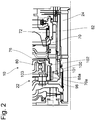
- Fig. 2 is an excerpt from with Fig. 1 shown and described above, wherein only the storage concept of the clutch 20 and the second torsional damper 22 was modified as explained below. The too Fig. 1 Introduced reference symbols have been retained.
- the coupling hub 70 which represents the intermediate shaft, at its end section 70a on the combustion engine side, is embodied here with external toothing, which meshes with an internally toothed tubular extension 88a of the torsion damper 22.
- the clutch hub 70 is also supported axially spaced therefrom by means of a bearing 100 which is arranged between the clutch hub 70 and the support hub 82 and is designed as a slide bearing. This is secured by means of a securing ring 101 and a thrust washer 103 interacting with the clutch hub 70.
- the bearing 80 is different from Fig 1 not directly, but only indirectly connected to the clutch hub 70.
- a tubular support element 102 is fixed on the wall area 76 of the centrifugal force pressure compensation chamber.
- the explained drive unit 10 offers extensive functionality with very little space requirements.
- the drive unit 10 can be arranged between the internal combustion engine and the transmission in an almost space-neutral manner because the torque converter is omitted.
- a wet clutch as described, a high starting performance is possible.
- a desired low mass moment of inertia is achieved with an internal electrical machine.
- the proposed drive unit is to be regarded as a modular system in which, in particular, the torsional damper, the active length of the electric machine and the transmission torque of the clutch can be varied by adjusting the number of plates.
- the second torsional damper can be arranged radially and completely or at least partially also axially within the receiving space formed by the electric machine.
- the first and / or the second torsion damper in one opposite direction Fig. 1 to train modified form.
- the second torsional damper can be designed using two functionally parallel single dampers whose hubs are rotationally driven with the intermediate shaft and whose output elements are connected to one another and interact with the transmission input shaft via a common hub element.
Landscapes
- Engineering & Computer Science (AREA)
- Chemical & Material Sciences (AREA)
- Combustion & Propulsion (AREA)
- Transportation (AREA)
- Mechanical Engineering (AREA)
- Arrangement Of Transmissions (AREA)
- Hybrid Electric Vehicles (AREA)
- Electric Propulsion And Braking For Vehicles (AREA)
Description
- Die Erfindung betrifft eine Antriebseinheit für ein wahlweise verbrennungs- und/oder elektromotorisch antreibbares Hybridfahrzeug gemäß dem Oberbegriff von Patentanspruch 1. Eine derartige Antriebseinheit wird beispielsweise in der
EP 1 736 345 A1 beschrieben. - Der vorliegenden Erfindung liegt das Problem zugrunde, eine kostengünstige, leicht zu montierende und zugleich kompakte Antriebseinheit zu schaffen, welche zugleich in der Lage ist, in Abhängigkeit vom jeweiligen Betriebszustand in einem Fahrzeugantriebsstrang auftretende Drehungleichförmigkeiten wirksam zu dämpfen.
- Die vorstehend genannten Aufgaben werden bei einer gattungsgemäßen Antriebseinheit durch die im Kennzeichen von Patentanspruch 1 genannten Merkmale gelöst.
- Es wird somit eine Antriebseinheit bereitgestellt, welche einen Verbrennungsmotor mit einer Abtriebswelle, ein Getriebe mit einer Eingangswelle und eine zwischen dem Verbrennungsmotor und dem Getriebe angeordnete elektrische Maschine mit einem Stator und mit einem Rotor umfasst, der zumindest mittelbar mit der Abtriebswelle des Verbrennungsmotors und mit der Getriebeeingangswelle zur Übertragung eines Drehmoments koppelbar ist. Zur besseren Entkopplung gegenüber im Antriebsstrang des Hybridfahrzeuges auftretenden Drehungleichförmigkeiten wird vorgeschlagen, die Antriebseinheit mit einem ersten und einem zweiten Torsionsdämpfer auszubilden, wobei zumindest der Rotor der elektrischen Maschine innerhalb eines zwischen den Torsionsdämpfern ausgebildeten Drehmomentübertragungswegs angeordnet ist. Die Antriebseinheit kann weiter eine im Drehmomentübertragungsweg zwischen dem Verbrennungsmotor und dem Getriebe angeordnete schaltbare Kupplung umfassen, jedoch kann diese auch außerhalb dieses Drehmomentübertragungsweges, also z.B. zwischen dem Verbrennungsmotor und dem ersten Torsionsdämpfer oder innerhalb des Gangwechselgetriebes angeordnet sein.
- Dadurch, dass zur Dämpfung der in einem Hybridfahrzeug auftretenden Torsionsschwingungen zwei in Reihe im Drehmomentübertragungsweg geschaltete einzelne Torsionsdämpfer eingesetzt werden, zwischen denen zumindest die Massenträgheit des Rotors der elektrischen Maschine wirksam wird, kann bei bestimmten Betriebszuständen insbesondere bei verbrennungsmotorischen Betrieb als auch bei elektromotorischen Betrieb oder einer gemischten Betriebsweise eine gegenüber dem Stand der Technik bessere Entkopplung gegenüber den Fahrkomfort beeinträchtigenden Antriebsstrangschwingungen erreicht werden. Bei dem verbrennungsmotorseitig angeordneten Torsionsdämpfer kann durch die sekundärseitige Verbindung mit dem Rotor der Elektromaschine und gegebenenfalls der Kupplung im Wesentlichen auf eine unmittelbare Masseanhäufung verzichtet werden. Der der Elektromaschine und gegebenenfalls der Kupplung im Drehmomentverlauf nachgelagerte Torsionsdämpfer kann daher auch entsprechend kompakt ausgeführt werden. Durch eine spezifische Ausgestaltung der einzelnen Torsionsdämpfer lässt sich das zu bedämpfende Frequenzspektrum insgesamt breitbandiger und effektiver abdecken. Die vorgeschlagene Antriebseinheit kann somit wesentlich zur Geräusch- und Verschleißminimierung an Verzahnungsstellen sowohl außerhalb als innerhalb des Getriebes beitragen.
- Vorteilhafte Ausführungen und Weiterbildungen der Erfindung sind den Unteransprüchen sowie der nachfolgenden Figurenbeschreibung und den beigefügten Figuren entnehmbar.
- Vorteilhafte Ausführungsformen und Weiterbildungen der Erfindung sind in den Unteransprüchen angegeben.
- Im Folgenden wird die Erfindung anhand der beigefügten Figuren beispielhaft beschrieben. Es zeigen:
- Fig. 1
- eine Antriebseinheit mit einem Verbrennungsmotor, einem Getriebe und mit zwei Torsionsdämpfern, zwischen denen funktional eine Elektromaschine und eine Kupplung angeordnet sind;
- Fig. 2
- einen Ausschnitt der in
Fig. 1 gezeigten Antriebseinheit mit einer demgegenüber modifizierten Lagerungsanordnung. - Die
Fig. 1 zeigt eine Antriebseinheit 10 mit einem Verbrennungsmotor 12 als eine erste Antriebsquelle mit einer als Kurbelwelle 14 ausgebildeten Abtriebswelle, deren Drehmoment über eine Koppelanordnung 16, einen ersten Torsionsdämpfer 18, eine schaltbare Kupplung 20 und einen zweiten Torsionsdämpfer 22 über eine Eingangswelle 24 in ein Gangwechselgetriebe 26 eingeleitet werden kann, um von dort über weitere, hier zeichnerisch nicht dargestellte Antriebsstrangelemente auf die Antriebsräder eines Hybridfahrzeuges übertragen zu werden. Die Antriebseinheit 10 weist weiter eine Elektromaschine 28 mit einem Stator 30 und einem Rotor 32 als eine zweite Antriebsquelle auf, dessen Drehmoment in den zwischen dem Verbrennungsmotor 12 und dem Getriebe 26 ausgebildeten Antriebsstrangabschnitt einleitbar ist. Das Getriebe 26 ist im vorliegenden Fall als ein gestuftes vollautomatisches Getriebe ausgeführt. Üblicherweise ist einem solchen Getriebe 26 ein hydrodynamischer Drehmomentwandler vorgeschaltet, der jedoch hierbei zugunsten der vorgenannten Funktionselemente entfallen ist. Es sei hervorgehoben, dass bei der vorliegenden Antriebseinheit 10 zwischen dem Verbrennungsmotor 12 und dem Getriebe 26 lediglich eine einzige, wahlweise schaltbare Kupplung 20 vorgesehen ist, die zum Anfahren als auch zum Gangwechsel das übertragene Drehmoment ganz oder nur zu einem gewissen Betrag begrenzen kann. - Nachstehen wird die Ausgestaltung des zwischen dem Verbrennungsmotor 12 und dem Getriebe 26 befindlichen Antriebsstrangabschnitts im Detail beschrieben.
- Die im Drehmomentweg auf die Kurbelwelle 14 folgende Koppelanordnung 16 umfasst zunächst eine axial flexible Drehmomentübertragungsplatte in Form einer Flexplate 34, die radial innen mittels Schraubbolzen 36 mit der Kurbelwelle 14 und radial außen wiederum über Bolzen 38 mit einer als Driveplate bezeichneten und im Wesentlichen axial steifen Übertragungsscheibe 40 verbunden ist. Durch diese Anbindung sind axiale Kurbelwellenschwingungen und eine sich ggf. beim Zusammenbau der Antriebseinheit 10 ergebende toleranzbedingte axiale Fehlpassung einfach kompensierbar. Auf diese Weise wird eine gegenseitige unerwünschte Verspannung von den im Drehmomentübertragungsweg zwischen dem Verbrennungsmotor 12 und dem Getriebe 26 befindlichen Funktionselementen sicher vermieden.
- Die Driveplate 40 ist in deren radial inneren Bereich zur Schaffung eines Bewegungsspielraums axial leicht gekröpft geformt und weist ein Hohlnabe 40a auf, die mittels einer Formschlussverbindung 42 mit einer Nabe 44a des ersten Torsionsdämpfers 18 in Drehmitnahmeverbindung steht. Die Formschlussverbindung 42 ist im vorliegenden Fall als axiale Formschlussverbindung, insbesondere als Hirth-Verzahnung ausgeführt, bei der die beiden Naben 40a; 44a mittels mehrer Schraubbolzen 43 axial verspannt sind. Radial innerhalb der verbundenen Naben 40a; 44a ist ein sich zumindest abschnittweise über beide Naben 40a; 44a erstreckendes Lager 46, was hier ein Wälzlager darstellt, ausgebildet bzw. angeordnet, über welches sich die Koppelanordnung 16 und der erste Torsionsdämpfer 18 auf der Eingangswelle 24 des Automatgetriebes 26 abstützen können bzw. welches eine Lagerstelle für die Getriebeeingangswelle 24 bereitstellt.
- Die der Kurbelwelle 14 abgewandte Nabe 44a bildet zugleich mit einem sich daran anschließenden und im Wesentlichen nach radial außen erstreckendem scheibenfömigen Deckblech 44b und mit einem daran mittels Nieten 44c verbundenem weiteren Deckblech 44d das Eingangsteil des ersten Torsionsdämpfers 18. Zwischen den Deckblechen 44b; 44d sind in Umfangsrichtung mehrere Kammern zur Aufnahme von Federn 44e ausgebildet, deren Enden sich jeweils einerseits an den Deckblechen 44b; 44d und andererseits an einem Ringkragen 44f eines Nabenelements 44g abstützen, das axial zwischen den Deckblechen 44b; 44d angeordnet ist und das diesen gegenüber über einen gewissen Drehwinkelbereich verdrehbar gelagert ist. In der
Fig. 1 ist erkennbar, dass der Federsatz 44e des ersten Torsionsdämpfers 18 den Stator 30 der Elektromaschine 28 radial erreicht und dass, das Ausgangsteil darstellende Nabenelement 44g im radial äußeren Bereich des Torsionsdämpfers 18 axial abgewinkelt ausgeführt ist und somit einen horizontalen Rohrfortsatz ausbildet, um dadurch einen topfförmigen Aufnahmeraum 48 zur Anordnung des zweiten Torsionsdämpfers 22 auszubilden. - Das Nabenelement 44g weist an der zu dem Getriebe 26 gewandten Seite eine Formschlussverbindung 50 zur Drehmitnahme eines sich hier im Wesentlichen radial erstreckenden Mitnehmerelements 52 auf, welches einen Teil eines Eingangsteils 52 der Kupplung 20 bildet. Dazu sind an den beiden als Blechumformteil gefertigten Elementen 44g; 52 Zahnprofile vorgesehen, deren Zähne und Lücken sich wechselseitig durchdringen können. Das Zahnprofil des Mitnehmerelements 52 ist in Form relativ langer Zahnfinger und in Richtung des korrespondierenden Profil etwas abgewinkelt ausgebildet, wodurch beim Zusammenfügen eine gewisse Federwirkung resultiert, die die Wirkpartner im Wesentlichen spielfrei in gegenseitiger Anlage hält, jedoch gleichzeitig einen Axial- und einen Radialausgleich zulässt.
- Die Kupplung 20 ist im vorliegenden Ausführungsbeispiel als nasslaufende Lamellenkupplung ausgeführt, wozu in einem radial inneren Abschnitt das Mitnehmerelement 52 mittels einer Nietverbindung 54 mit einem radial außen verzahnten Innenlamellenträger 56 fest verbunden ist, auf dem eine Mehrzahl dort axial verlagerbarer Innenlamellen angeordnet sind, welche in die Zwischenräume von mehreren, auf einem dazu radial beabstandeten und ebenfalls verzahnten Außenlamellenträger 58 axial verlagerbaren Außenlamellen eingreifen und zu diesen in eine Reibschlussverbindung gebracht werden können.
- Das gesamte aus den Lamellen gebildete Paket kann mittels eines druckbeaufschlagbaren hydraulischen Kolbens 60 einer Betätigungseinrichtung 62 entgegen der Wirkung einer hier als Schraubendruckfeder ausgebildeten Rückstellelementes 64 belastet werden, wodurch die Drehmomentübertragung zwischen dem Außen- 58 und dem Innenlamellenträger 56 und den nachfolgenden Elementen gesteuert wird. Bevorzugt werden bei der Lamellenkupplung die Innenlamellen als Reiblamellen ausgeführt wie dieses in der
Fig. 1 erkennbar ist. Der Kolben 60 bildet dabei eine Begrenzung eines innerhalb eines Druckmittelzylinders 66 ausgebildeten Druckraums 68. Dieser Druckraum 68 wird weiterhin durch einen radial verlaufenden Abschnitt des Außenlamellenträgers 58 und durch eine fest mit diesem verbundene hohl ausgeführte Kupplungsnabe 70 begrenzt. Die Kupplungsnabe 70 stellt eine Zwischenwelle dar, die wiederum fest mit einer Pumpennabe 72 verbunden ist, welche sich über die Getriebeglocke 26a bzw. das Getriebegehäuse 26b mittels eines Lagers 74 abgestützt. Die Pumpennabe 72 ist Bestandteil einer an dem Getriebe 26 angeordnete Pumpe, mittels der ein Fluiddruck aufgebaut werden kann und im Ergebnis ein Ölaustausch zwischen der Kupplung 20 und dem Getriebe 26 ermöglicht wird. - Zwischen dem Kolben 60 einerseits und dem Außenlamellenträger 58 und der Kupplungsnabe 70 andererseits sind jeweils Dichtelemente vorgesehen. Zu dem Druckmittelzylinder 66 gehört weiterhin ein verbrennungsmotorseitig axial zum Kolben 60 beabstandeter Wandungsbereich 76, der gemeinsam mit dem Kolben 60 und einem Abschnitt der Kupplungsnabe eine Fliehkraft-Druckausgleichskammer 78 begrenzt, der radial außen mittels eines mit dem Kolben 60 zusammenwirkenden Dichtelementes abgedichtet ist.
- Mit einem noch weiteren Abschnitt ist die Kupplungsnabe 70 als Lagerstelle zur Lagerung des Kupplungseingangselementes, hier insbesondere des Innenlamellenträgers 56, ausgebildet bzw. zur Aufnahme eines Lagers vorgesehen, wobei im vorliegenden Fall in dem genannten Abschnitt ein Wälzlager 80 angeordnet ist. Gemäß einer Abwandlung kann auch vorgesehen sein, dass das Eingangsteil der Kupplung 20 fest mit der Kupplungsnabe 70 verbunden ist, während das Ausgangsteil drehbar auf der Nabe 70 gelagert ist.
- In der
Fig. 1 ist weiter zu sehen, dass die Getriebeeingangswelle 24 hohl ausgeführt ist und dass sich radial zwischen dieser und der Kupplungsnabe 70 eine getriebefest angeordnete, rohrförmige Stütznabe 82 in Richtung des Verbrennungsmotors 12 erstreckt, die gemeinsam mit der Kupplungsnabe 70 auf etwa derselben Axiallage endet. - Innerhalb als auch zwischen der Getriebeeingangswelle 24, der Stütznabe 82 und der Zwischenwelle bzw. Kupplungsnabe 70 sind durch radiale Zwischenräume und Radialöffnungen Fluidkanäle ausgebildet, die zur Betätigung der Kupplung 20 eine Fluidverbindung zwischen einem im Getriebe 26 vorgesehenen Fluidkreislauf einerseits und dem Betätigungskolben 60 der Kupplung 20 und der Fliehkraft-Druckausgleichskammer 78 andererseits schaffen.
- Der Wandungsbereich der Fliehkraft-Druckausgleichskammer 78 ist radial innen, in der Nähe der Lagerstelle 80 durchbrochen, so dass Fluid von dort nach radial außen an die Innenseite des Innenlamellenträgers 56 transportiert werden kann, wo es durch dort vorgesehene Öffnungen zur Kühlung in die Lamellenzwischenräume eintreten und von dort beispielsweise über Öffnungen im Außenlamellenträger 58 noch weiter nach radial außen befördert werden kann.
- Es ist somit bezüglich der Kupplung 20 erkennbar, dass diese als "Normally-Open-Typ" zur gedrückten Betätigung ausgeführt ist. Es ist auch gemäß einer Abwandlung des dargestellten Ausführungsbeispiels möglich, das Eingangsteil der Kupplung 20 als Außenlamellenträger auszuführen.
- Die Ansteuerung der Kupplungen 20 wird von einem zeichnerisch nicht dargestellten Getriebesteuergerät übernommen. Die Abtrennung des durch die Nasskupplung 20 geschaffenen Nassraumes erfolgt einerseits durch das Getriebegehäuse 26b, genauer durch eine das Getriebe 26 begrenzende Stirnwand 26c und durch die Getriebeglocke 26a. Zusätzlich kann zur axialen Bauraumverlängerung bei Bedarf ein Zwischengehäuse eingefügt werden. Zum Weiteren ist axial zwischen der Driveplate 40 und dem Eingangsteil 44b des ersten Torsionsdämpfers 18 eine Zwischenwand 84 angeordnet, welche radial außen an der Getriebeglocke 26a befestigt ist und die radial innen mittels eines dort eingesetzten Wellendichtringes 86 mit der Nabe 40a der Driveplate 40 in Dichtkontakt steht. Die Koppelanordnung 16, bestehend aus Flex- und Driveplate 34; 40 befindet sich somit in einem gegenüber dem Nassraum abgegrenzten Trockenraum.
- In dem bisher beschriebenen, vom Verbrennungsmotor 12 beginnenden Drehmomentübertragungsgweg folgt der Kupplung 20 der zweite Torsionsdämpfer 22, der innerhalb des Aufnahmeraums 48 des ersten Torsionsdämpfers 18 angeordnet ist. Der zweite Torsionsdämpfer 22 umfasst ein als Nabenelement 88 gestaltetes Eingangsteil, welches axial zwischen zwei miteinander fest verbundenen, das Ausgangsteil bildende Deckblechen 90a, b angeordnet ist und entgegen der Wirkung eines wiederum in Kammern zwischen diesen Teilen eingespannten Federsatzes 92 relativ um einen bestimmten Betrag zueinander verdrehbar sind. Die Einleitung eines von der Kupplung 20 übertragenen Drehmoments erfolgt über eine als Steckverzahnung ausgebildete Formschlussverbindung 94 zwischen der Kupplungsnabe 70 und einen in diese axial eingeführten Rohrfortsatz 88a des Nabenelements 88.
- Es ist in der
Fig. 1 ersichtlich, dass sich der zweite Torsionsdämpfer 22 mit dessen Rohrfortsatz 88a über ein weiteres Lager 96, welches hier ein Wälzlager darstellt, auf der getriebefesten Stütznabe 82 abstützt. Zur Ausbildung einer weiteren Lagerstelle und zum Zweck der Drehmomentübertragung ist am radial inneren Bereich des zum Verbrennungsmotor 12 weisenden Deckblechs 90b eine innenverzahnte Nabe 98 vorgesehen, welche auf die in diesem Abschnitt außenverzahnte Eingangswelle 24 des Getriebes 26 aufgeschoben und mittels eines Sicherungsringes 97 axial gesichert ist, wobei die Getriebeeingangswelle 24 selbst mittels des Lagers 46 abgestützt ist. Zusätzlich ist zwischen dem Eingangsteil, d.h. dem Nabenelement 88 und dem Ausgangsteil, insbesondere der Nabe 98 ein Axiallager eingefügt. Zur Erzeugung einer axialen Vorspannung des zweiten Torsionsdämpfers 22 in Richtung der Kupplung 20 wirkt zwischen dem Sicherungsring 97 und der Nabe 98 eine Tellerfeder 99. - Um das Fahrzeug bei Bedarf neben einer reinen verbrennungsmotorischen Betriebsweise alternativ auch rein elektromotorisch oder in einer gemischten Betriebsweise antreiben zu können, weist die Antriebseinheit 10 wie bereits erwähnt eine Elektromaschine 28 auf, die vorliegend als permanenterregte Synchronmaschine in Innenläuferbauart ausgeführt ist. Der Stator 30 ist über einen Statorträger 30a mittels einer hier nicht gezeigten Verschraubung innerhalb der Getriebeglocke 26a drehfest abgestützt angeordnet. Hinsichtlich deren elektromagnetischen Wirkungsweise ist die spezielle Bauart der Elektromaschine 28 für die weiteren Ausführungen unerheblich, d.h. diese kann auch als Asynchronmaschine; Reluktanzmaschine oder dgl. vorgesehen sein.
- Je nach der vorgesehenen aktiven Länge der Elektromaschine 28 kann zu deren Aufnahme bei Notwendigkeit auch ein den axialen und/oder radialen Bauraum erweiterndes Zwischengehäuse vorgesehen sein.
- Der innerhalb des Stators 30 drehbar gelagerte Rotor 32 ist drehfest mit dem Außenlamellenträger 58 der Kupplung 20 verbunden und weist ein lamelliertes Rotorjoch auf, an dessen Außenumfangsfläche eine Mehrzahl von Permanentmagneten angeordnet ist, deren Magnetfeld mit einem von einem Wicklungssystem des Stators 30 erzeugten weiteren Magnetfeld wechselwirken und somit den Rotor 32 antreiben kann und zum Antrieb des Fahrzeuges oder dem Starten des Verbrennungsmotors 12 dienen kann. Insofern stellt der Außenlamellenträger 58 gleichzeitig einen Rotorträger dar. Der Außenlamellenträger bzw. der Rotorträger 58 ist in der
Fig. 1 mit einem axialen Abschnitt 58a und einem radialen Abschnitt 58b zunächst zweiteilig ausgeführt, wobei die beiden Teile 58a, b mittels einer Fügeverbindung, z.B. einer Schweißnaht miteinander verbunden werden. Alternativ kann dieser auch einteilig, z.B. als Blechumformteil geformt sein. Die Kupplung 20 befindet sich damit einschließlich des zugehörigen Betätigungsorgans 66 radial und axial innerhalb des von der Elektromaschine 28, insbesondere des vom Rotor 32 umschlossenen Aufnahmeraums. Die Elektromaschine 28 befindet sich damit ebenfalls innerhalb des zuvor beschrieben Nassraums und kann damit gleichzeitig von dem sich dort unter einer Fliehkraftwirkung ausbreitenden Fluid-Luft-Gemisches gekühlt werden. Des Weiteren ist innerhalb des Statorträgers 30a ein umlaufender Kühlkanal 30b vorgesehen, indem ein Kühlfluid, beispielsweise über eine Strömungsverbindung zu einem Getriebeölkreislauf, zirkulieren und dabei ggf. auch die Statorspulenköpfe mit dem Fluid benetzten kann. Alternativ kann der Rotor 32 gemäß einer modifizierten Bauweise auch mit dem Eingangsteil der Kupplung 56 verbunden sein. - Durch die Implementierung der beschriebenen Antriebseinheit 10 wird ein vielseitiger Hybridantrieb dargestellt, welcher bei Abkopplung des Verbrennungsmotors 12 durch Öffnen der Kupplung 20 einen alleinigen elektromotorischen Fahrbetrieb ermöglicht. Die elektrische Maschine 28 kann im Motorbetrieb die Pumpenanordnung des Automatikgetriebes 26 direkt antreiben und ermöglicht somit auch während des rein elektrischen Fahrbetriebes sämtliche hydraulischen Getriebefunktionen.
- Die elektrische Maschine 28 kann bei geschlossener Kupplung einen Schwungstart zum Starten des Verbrennungsmotors 12 ausführen. Die Antriebseinheit 10 ist so konzipiert, dass zwischen der Kurbelwelle 14 und dem Rotor 32 ein möglichst geringes Trägheitsmoment auftritt, um dadurch einen möglichst schnellen Motorstart zu ermöglichen.
- Das Schließen der Kupplung 20 bei rotierendem Rotor 32, d.h. das Hinzuschalten des stehenden Verbrennungsmotors 12 kann in der Weise erfolgen, dass das Antriebsmoment der Elektromaschine 28 in dem Maße erhöht wird, wie der Startvorgang des Verbrennungsmotors 12 es erfordert. Das Antriebsmoment auf die Räder bleibt hierbei unbeeinflusst, somit bleibt den Fahrzeuginsassen dieser Vorgang weitestgehend verborgen.
- Es ist jedoch für einen Direktstart auch möglich, den stehenden Verbrennungsmotor 12 mittels der geschlossenen Kupplung 20 drehfest an den Rotor 32 der elektrischen Maschine zu koppeln und beide Aggregate im Verein aus dem Stand hochzudrehen.
- Der Fahrbetrieb mit Verbrennungsmotor 12 erfolgt mit geschlossener Kupplung 20. Die elektrische Maschine 28 läuft hierbei im Generatorbetrieb mit. Während des Fahrbetriebes kann der Generatorbetrieb im Bedarfsfall jedoch für eine bestimmte Zeit unterbrochen werden, damit die elektrische Maschine 28 im Motorbetrieb den Verbrennungsmotor 12 unterstützen kann und somit ein zusätzliches Drehmoment in den Fahrzeugantriebsstrang einleiten kann.
- Bei Fahrzeugstillstand ist die elektrische Maschine 28 bei geöffneter Kupplung 20 in der Lage, mittels geringer Antriebsdrehzahlen den Fluiddruck im Getriebe 26 aufrechtzuerhalten.
- Bei der Montage der Antriebseinheit 10 werden zunächst die Elektromaschine 28 und die Kupplung 20 einschließlich deren Betätigungseinrichtung 66 in die Getriebeglocke 26a eingesetzt, wobei der Stator 30 mit dieser oder mit einem Zwischengehäuse verschraubt wird und der Rotor 32 gemeinsam mit der Kupplung 20 mittels der Kupplungsnabe 70 in die Pumpennabe 72 eingeführt wird. Danach können der zweite und der erste Torsionsdämpfer 22; 18 auf die Getriebeeingangswelle 24 bzw. die Kupplungsnabe 70 aufgesteckt werden, wobei das Ausgangsteil 44g des ersten Torsionsdämpfers 18 mit dem Mitnehmerelement 52 der Kupplung 20 in Eingriff gelangt. Anschließend kann die den Nass- vom Trockenraum abtrennende Zwischenwand 84 an der Getriebeglocke 26a festgelegt und die Driveplate 40 mit dem Eingangsteil 44a des ersten Torsionsdämpfers 18 verschraubt werden. Beim Zusammenfügen von Verbrennungsmotor 12 und Getriebe 26 gelangen dann die von der Driveplate 40 axial abstehenden Bolzen 38 mit entsprechenden Öffnungen der bereits vorab mit der Kurbelwelle 14 verbunden Flexplate 34 in Eingriff.
- In
Fig. 2 ist ein Ausschnitt der mitFig. 1 gezeigten und vorstehend beschriebenen Antriebseinheit gezeigt, wobei lediglich das Lagerungskonzept der Kupplung 20 und des zweiten Torsionsdämpfers 22 wie nachfolgend erläutert, modifiziert wurde. Die zuFig. 1 eingeführten Bezugszeichen wurden beibehalten. - Im direkten Vergleich zu
Fig. 1 ist bei der Antriebseinheit 10 in derFig. 2 die die Zwischenwelle darstellende Kupplungsnabe 70 an deren verbrennungsmotorseitigem Endabschnitt 70a hier mit einer Außenverzahnung ausgeführt, welche mit einem innenverzahnten Rohrfortsatz 88a des Torsionsdämpfers 22 in Eingriff steht. Die Kupplungsnabe 70 erfährt neben der Lagerung innerhalb der Pumpennabe 72 eine weitere, axial davon beabstandete Lagerung mittels eines zwischen der Kupplungsnabe 70 und der Stütznabe 82 angeordneten Lagers 100, welches als Gleitlager ausgebildet ist. Dieses ist mittels eines Sicherungsringes 101 und einer mit der Kupplungsnabe 70 zusammenwirkenden Anlaufscheibe 103 gesichert. - Das Lager 80 ist in Abweichung von
Fig 1 nicht unmittelbar, sondern lediglich mittelbar mit der Kupplungsnabe 70 verbunden. Zur Aufnahme des Lagers 80 ist gemäßFig. 2 ein am Wandungsbereich 76 der Fliehkraft-Druckausgleichskammer rohrförmiges Tragelement 102 festgelegt. - Zusammengefasst bietet die erläuterte Antriebseinheit 10 eine umfangreiche Funktionalität bei sehr geringem Platzbedarf. Die Antriebseinheit 10 kann bezüglich der von Verbrennungsmotor und einem Automatgetriebe gebildeten Einheit durch den Entfall des Drehmomentwandlers nahezu bauraumneutral zwischen dem Verbrennungsmotor und dem Getriebe angeordnet werden. Durch den Einsatz einer nasslaufenden Kupplung gemäß der Beschreibung ist eine hohe Anfahrleistung möglich. Zudem wird mit einer innenlaufenden elektrischen Maschine ein gewünschtes geringes Massenträgheitsmoment realisiert. Gemäß einem weiteren Aspekt ist die vorgeschlagene Antriebseinheit als ein Baukastensystem zu betrachten, bei dem insbesondere die Torsionsdämpfer, die aktive Länge der Elektromaschine und das Übertragungsmoment der Kupplung durch Anpassung der Lamellenanzahl variiert werden können.
- So kann beispielsweise auf der Grundlage der mit den
Fig. 1 ,2 erläuterten Antriebseinheit gemäß einer weiteren, hier zeichnerisch nicht dargestellten Variante mit einer gegenüberFig. 1 verlängerten Elektromaschine zumindest der zweite Torsionsdämpfer, gegebenfalls auch der erste Torsionsdämpfer, radial und vollständig oder zumindest teilweise auch axial innerhalb des von der Elektromaschine gebildeten Aufnahmeraums angeordnet werden. Es ist unabhängig davon auch möglich, den ersten und/oder den zweiten Torsionsdämpfer in einer gegenüberFig. 1 abgewandelten Form auszubilden. Dazu kann beispielsweise der zweite Torsionsdämpfer mittels zwei funktional parallel arbeitender Einzeldämpfern ausgeführt sein, deren Naben mit der Zwischenwelle in Drehmitnahme stehen und deren Ausgangselemente miteinander verbunden sind und über ein gemeinsames Nabenelement mit der Getriebeeingangswelle zusammenwirken. -
- 10
- Antriebseinheit
- 12
- Verbrennungsmotor
- 14
- Kurbelwelle
- 16
- Koppelanordnung
- 18
- erster Torsionsdämpfer
- 20
- Kupplung
- 22
- zweiter Torsionsdämpfer
- 24
- Eingangswelle
- 26
- Getriebe
- 26a
- Getriebeglocke
- 26b
- Getriebegehäuse
- 26c
- Stirnwand
- 28
- Elektromaschine
- 30
- Stator
- 32
- Rotor
- 34
- Flexplate
- 36, 38
- Bolzen
- 40
- Driveplate
- 40a
- Hohlnabe
- 42
- Formschlussverbindung
- 43
- Bolzen
- 44a
- Nabe
- 44b, d
- Deckblech
- 44c
- Niet
- 44e
- Feder, Federsatz
- 44f
- Ringkragen
- 44g
- Nabenelement
- 46
- Lager
- 48
- Aufnahmeraum
- 50
- Formschlussverbindung
- 52
- Mitnehmerelement
- 54
- Nietverbindung
- 56
- Innenlamellenträger
- 58
- Außenlamellenträger
- 60
- Kolben
- 62
- Betätigungseinrichtung
- 64
- Rückstellelement
- 66
- Druckmittelzylinder
- 68
- Druckraum
- 70
- Kupplungsnabe, Zwischenwelle
- 70a
- Endabschnitt
- 72
- Pumpennabe
- 74
- Lager
- 76
- Wandungsbereich
- 78
- Fliehkraft-Druckausgleichskammer
- 80
- Lager
- 82
- Stütznabe
- 84
- Zwischenwand
- 86
- Wellendichtring
- 88
- Nabenelement
- 88a
- Rohrfortsatz
- 90a, b
- Deckblech
- 92
- Federsatz
- 94
- Formschlussverbindung
- 96
- Lager
- 97
- Sicherungsring
- 98
- Nabe
- 99
- Tellerfeder
- 100
- Lager
- 101
- Sicherungsring
- 102
- Tragelement
- 103
- Anlaufscheibe
Claims (15)
- Antriebseinheit (10) für ein Hybridfahrzeug umfassend- einen Verbrennungsmotor (12) mit einer Abtriebswelle (14),- ein Getriebe (26) mit einer Eingangswelle (24),- eine zwischen dem Verbrennungsmotor (12) und dem Getriebe (26) angeordnete elektrische Maschine (28) mit einem Stator (30) und mit einem Rotor (32), der zumindest mittelbar mit der Abtriebswelle (14) des Verbrennungsmotors (12) und mit der Getriebeeingangswelle (24) zur Übertragung eines Drehmoments koppelbar ist, wobei- die Antriebseinheit (10) einen ersten Torsionsdämpfer (18) mit einem Eingangs- (44b, d) und einem Ausgangsteil (44f, g) und einen zweiten Torsionsdämpfer (22) mit einem Eingangs- (88) und einem Ausgangsteil (90b, 98) aufweist, wobei zumindest der Rotor (32) der elektrischen Maschine (28) innerhalb eines zwischen den Torsionsdämpfern (18; 22) ausgebildeten Drehmomentübertragungswegs angeordnet ist,
dadurch gekennzeichnet,
dass der erste und der zweite Torsionsdämpfer (18; 22) bezüglich der elektrischen Maschine (28) auf einer gemeinsamen Axialseite angeordnet sind. - Antriebseinheit nach Anspruch 1,
dadurch gekennzeichnet,
dass der erste und der zweite Torsionsdämpfer (18; 22) radial gestaffelt zueinander angeordnet sind und sich gegenseitig zumindest teilweise axial überdecken. - Antriebseinheit nach einem der vorherigen Ansprüche,
dadurch gekennzeichnet,
dass der zweite, im Drehmomentübertragungsweg getriebeseitig angeordnete Torsionsdämpfer (22) radial innerhalb des ersten, im Drehmomentübertragungsweg verbrennungsmotorseitig angeordneten Torsionsdämpfers (18) angeordnet ist. - Antriebseinheit nach einem der vorherigen Ansprüche, wobei im Drehmomentübertragungsweg zwischen dem Verbrennungsmotor (12) und dem Getriebe (26) eine Kupplung (20) angeordnet ist,
dadurch gekennzeichnet,
dass das Ausgangsteil (44g) des ersten Torsionsdämpfers (18) mittels einer Formschlussverbindung (50) mit einem Eingangsteil (52) der Kupplung (20) in Drehmitnahmeverbindung steht. - Antriebseinheit nach einem der vorherigen Ansprüche,
dadurch gekennzeichnet,
dass die Kupplung (20) zumindest teilweise innerhalb eines von der elektrischen Maschine (28) gebildeten Aufnahmeraums angeordnet ist. - Antriebseinheit nach einem der vorherigen Ansprüche,
dadurch gekennzeichnet,
dass der Rotor (32) der elektrischen Maschine (28) einen Rotorträger (58) umfasst, der in Baueinheit mit dem Eingangs- oder einem Ausgangsteil der Kupplung (20) ausgeführt ist. - Antriebseinheit nach einem der vorherigen Ansprüche,
dadurch gekennzeichnet,
dass der Rotorträger (58) drehfest mit einer koaxial um die Getriebeeingangswelle (24) angeordneten und am Getriebe (26) gelagerten Zwischenwelle (70) verbunden ist. - Antriebseinheit nach einem der vorherigen Ansprüche,
dadurch gekennzeichnet,
dass das Eingangs- (56) oder das Ausgangsteil (58) der Kupplung (20) zumindest mittelbar auf der Zwischenwelle (70) drehbar gelagert ist, während das jeweils andere von Eingangsteil (56) und Ausgangsteil (58) drehfest mit der Zwischenwelle (70) verbunden ist. - Antriebseinheit nach einem der vorherigen Ansprüche,
dadurch gekennzeichnet,
dass der zweite Torsionsdämpfer (22) mit dessen Eingangsteil (88) auf einer getriebeseitig angeordneten und radial zwischen der Zwischenwelle (70) und der Getriebeeingangswelle (24) angeordneten Stütznabe (82) gelagert ist und dass das Ausgangsteil (90b; 98) dieses Torsionsdämpfers (22) drehfest mit der Getriebeeingangswelle (24) gekoppelt ist. - Antriebseinheit nach einem der vorherigen Ansprüche,
dadurch gekennzeichnet,
dass die Kupplung (20) als Lamellenkupplung ausgebildet ist. - Antriebseinheit nach einem der vorherigen Ansprüche,
dadurch gekennzeichnet,
dass die Kupplung (20) als "Normally-Open-Kupplung" zur gedrückten Betätigung ausgeführt ist. - Antriebseinheit nach einem der vorherigen Ansprüche,
dadurch gekennzeichnet,
dass die Getriebeeingangswelle (24), die Stütznabe (82) und die Zwischenwelle (70) Fluidkanäle aufweisen, die eine Fluidverbindung zwischen einem im Getriebe (26) vorgesehenen Fluidkreislauf einerseits und einem Fluiddruckraum (68) der Kupplung (20) und einer Fliehkraft-Druckausgleichskammer (78) andererseits ausbilden. - Antriebseinheit nach einem der vorherigen Ansprüche,
dadurch gekennzeichnet,
dass die Torsionsdämpfer (18; 22), die elektrische Maschine (28) und die Kupplung (20) innerhalb eines Nassraums angeordnet sind, der durch ein Getriebegehäuse (26b, c) und durch eine verbrennungsmotorseitig an diesem angeordnete Zwischenwand (84) begrenzt ist. - Antriebseinheit nach einem der vorherigen Ansprüche,
dadurch gekennzeichnet,
dass die Kupplungsnabe (70) unmittelbar auf der Getriebeeingangswelle (24) gelagert ist. - Antriebseinheit nach einem der vorherigen Ansprüche,
dadurch gekennzeichnet,
dass zumindest ein Torsionsdämpfer (18, 22) radial und zumindest teilweise axial innerhalb des von der Elektromaschine (28) gebildeten Aufnahmeraums angeordnet ist.
Applications Claiming Priority (1)
| Application Number | Priority Date | Filing Date | Title |
|---|---|---|---|
| DE102009045727A DE102009045727A1 (de) | 2009-10-15 | 2009-10-15 | Antriebseinheit für ein Hybridfahrzeug |
Publications (3)
| Publication Number | Publication Date |
|---|---|
| EP2311680A2 EP2311680A2 (de) | 2011-04-20 |
| EP2311680A3 EP2311680A3 (de) | 2018-05-02 |
| EP2311680B1 true EP2311680B1 (de) | 2020-10-07 |
Family
ID=43530051
Family Applications (1)
| Application Number | Title | Priority Date | Filing Date |
|---|---|---|---|
| EP10186961.8A Active EP2311680B1 (de) | 2009-10-15 | 2010-10-08 | Antriebseinheit für ein Hybridfahrzeug |
Country Status (3)
| Country | Link |
|---|---|
| US (1) | US8556010B2 (de) |
| EP (1) | EP2311680B1 (de) |
| DE (1) | DE102009045727A1 (de) |
Families Citing this family (30)
| Publication number | Priority date | Publication date | Assignee | Title |
|---|---|---|---|---|
| JP5278774B2 (ja) * | 2010-08-06 | 2013-09-04 | アイシン・エィ・ダブリュ株式会社 | 車両用駆動装置 |
| US8813935B2 (en) * | 2011-01-12 | 2014-08-26 | Gm Global Technology Operations, Llc | Launch / disconnect clutch for P2 hybrid powertrain |
| JP5149973B2 (ja) * | 2011-02-07 | 2013-02-20 | 株式会社エクセディ | トルク伝達装置 |
| JP5779947B2 (ja) * | 2011-04-07 | 2015-09-16 | コベルコ建機株式会社 | ハイブリッド建設機械 |
| DE102012214327A1 (de) * | 2012-08-10 | 2014-02-13 | Engineering Center Steyr Gmbh & Co. Kg | Antriebseinheit für ein Hybridfahrzeug |
| FR2995834B1 (fr) * | 2012-09-25 | 2014-09-05 | Valeo Equip Electr Moteur | Ensemble de transmission pour vehicule automobile |
| EP2900503B1 (de) | 2012-09-25 | 2018-04-25 | Valeo Equipements Electriques Moteur | Vorrichtung für ein hybridfahrzeug mit einem staubring zwischen einer elektrischen maschine und einer reaktionsscheibe |
| DE102012219697A1 (de) | 2012-10-29 | 2014-04-30 | Zf Friedrichshafen Ag | Antriebseinheit für ein Hybridfahrzeug und Verfahren zum Betreiben desselben |
| CN107532678B (zh) * | 2015-05-20 | 2020-09-11 | 舍弗勒技术股份两合公司 | 扭转振动减振器和混合动力驱动系 |
| DE102016211945A1 (de) * | 2016-06-30 | 2018-01-04 | Zf Friedrichshafen Ag | Drehmomentübertragungsvorrichtung |
| DE102016211942A1 (de) * | 2016-06-30 | 2018-01-04 | Zf Friedrichshafen Ag | Hybridantriebsmodul für einen Kraftfahrzeugantriebsstrang, sowie Kraftfahrzeugantriebsstrang |
| CN107839475B (zh) * | 2016-09-20 | 2022-08-30 | 博格华纳公司 | 用于混合动力汽车传动系的扭矩传递装置 |
| DE102016225972B4 (de) * | 2016-12-22 | 2025-12-31 | Zf Friedrichshafen Ag | Getriebe für ein Kraftfahrzeug |
| DE102017129274A1 (de) * | 2017-03-06 | 2018-09-06 | Schaeffler Technologies AG & Co. KG | Montage- und Demontageverfahren für Hybridmodule |
| DE102017205942A1 (de) * | 2017-04-06 | 2018-10-11 | Bayerische Motoren Werke Aktiengesellschaft | Antriebsvorrichtung mit einer Kupplungseinrichtung, Antriebssystem mit dieser Antriebsvorrichtung und Verfahren zum Betrieb des Antriebsystems |
| CN108150644B (zh) * | 2017-12-25 | 2021-02-12 | 贵州凯星液力传动机械有限公司 | 一种用于变速器的整体式离合器活塞 |
| FR3078122B1 (fr) * | 2018-02-20 | 2020-09-04 | Valeo Embrayages | Dispositif de transmission pour vehicule hybride |
| DE102018211374B4 (de) * | 2018-07-10 | 2025-09-11 | Zf Friedrichshafen Ag | Rotorträger für eine elektrische Maschine |
| DE102018211377B4 (de) * | 2018-07-10 | 2025-10-02 | Zf Friedrichshafen Ag | Rotorträger für eine elektrische Maschine |
| DE102018211376B4 (de) * | 2018-07-10 | 2025-10-09 | Zf Friedrichshafen Ag | Rotorträger für eine elektrische Maschine |
| KR20200056839A (ko) * | 2018-11-15 | 2020-05-25 | 현대자동차주식회사 | 모터 장착 엔진의 댐퍼 |
| DE102019001959B4 (de) * | 2019-03-20 | 2021-04-08 | Daimler Ag | Hybridantriebsystem |
| DE102019125872A1 (de) * | 2019-09-25 | 2021-03-25 | Schaeffler Technologies AG & Co. KG | Hybridantriebsstrang |
| JP7321426B2 (ja) * | 2019-11-18 | 2023-08-07 | マツダ株式会社 | 動力伝達装置 |
| DE102020105982B4 (de) * | 2019-11-21 | 2025-12-31 | Schaeffler Technologies AG & Co. KG | Antriebseinheit |
| KR102238842B1 (ko) * | 2019-12-20 | 2021-04-12 | 현대트랜시스 주식회사 | 하이브리드 차량용 동력전달장치 |
| DE102020200533A1 (de) | 2020-01-17 | 2021-07-22 | Zf Friedrichshafen Ag | Lageranordnung für ein Maschinenelement |
| DE102020200530A1 (de) | 2020-01-17 | 2021-07-22 | Zf Friedrichshafen Ag | Lageranordnung für ein Maschinenelement |
| JP7770428B2 (ja) * | 2021-07-07 | 2025-11-14 | シェフラー テクノロジーズ アー・ゲー ウント コー. カー・ゲー | 電気エネルギーを生成するための電気機械および車両用ハイブリッド駆動ユニット |
| US12466251B2 (en) | 2023-03-19 | 2025-11-11 | Customachinery Inc. | Transmission system for a hybrid drive unit |
Family Cites Families (8)
| Publication number | Priority date | Publication date | Assignee | Title |
|---|---|---|---|---|
| DE19934936B4 (de) * | 1998-07-28 | 2011-06-22 | Schaeffler Technologies GmbH & Co. KG, 91074 | Antriebsstrang |
| DE10005996A1 (de) * | 1999-03-02 | 2000-09-07 | Mannesmann Sachs Ag | Drehmomentübertragungseinheit |
| FR2791009B1 (fr) * | 1999-03-19 | 2001-04-27 | Valeo | Ensemble constitue d'un embrayage associe a une machine electrique, en particulier pour vehicule automobile |
| EP1736345A1 (de) | 2005-06-22 | 2006-12-27 | Zf Friedrichshafen Ag | Elektromotorisches Antriebsmodul |
| DE102005053887A1 (de) * | 2005-11-11 | 2007-05-16 | Zahnradfabrik Friedrichshafen | Elektromotorisches Antriebsmodul |
| US7509802B2 (en) * | 2006-09-26 | 2009-03-31 | Ford Global Technologies, Llc | Drive unit for hybrid electric vehicle |
| CN101595320B (zh) * | 2007-01-29 | 2011-11-30 | 舍弗勒技术两合公司 | 具有湿式起动离合器的混合应用的动力总成系统 |
| DE102007043737A1 (de) * | 2007-09-13 | 2009-03-26 | Daimler Ag | Antriebsmodul |
-
2009
- 2009-10-15 DE DE102009045727A patent/DE102009045727A1/de not_active Ceased
-
2010
- 2010-10-08 EP EP10186961.8A patent/EP2311680B1/de active Active
- 2010-10-15 US US12/905,712 patent/US8556010B2/en not_active Expired - Fee Related
Non-Patent Citations (1)
| Title |
|---|
| None * |
Also Published As
| Publication number | Publication date |
|---|---|
| US20110088958A1 (en) | 2011-04-21 |
| DE102009045727A1 (de) | 2011-04-21 |
| EP2311680A3 (de) | 2018-05-02 |
| US8556010B2 (en) | 2013-10-15 |
| EP2311680A2 (de) | 2011-04-20 |
Similar Documents
| Publication | Publication Date | Title |
|---|---|---|
| EP2311680A2 (de) | Antriebseinheit für ein Hybridfahrzeug | |
| EP1584830B1 (de) | Kupplungseinrichtung, insbesondere Anfahrkupplungseinrichtung | |
| EP3448706B1 (de) | Hybridmodul und antriebsanordnung für ein kraftfahrzeug | |
| EP2577108B1 (de) | Drehschwingungsdämpfungsanordnung | |
| DE102010030690A1 (de) | Antriebseinheit für ein Hybridfahrzeug | |
| EP1306572B1 (de) | Eingangsseitig zentral an einer Drehwelle oder Drehkomponente angebundene Kupplungseinrichtung in einem Kraftfahrzeug-Antriebsstrang | |
| DE10146606A1 (de) | Mehrfach-Kupplungseinrichtung mit axial nebeneinander angeordneten Lamellen-Kupplungsanordnungen | |
| EP1736345A1 (de) | Elektromotorisches Antriebsmodul | |
| DE102008057648A1 (de) | Kraftübertragungsvorrichtung, insbesondere zur Leistungsübertragung zwischen einer Antriebsmaschine und einem Abtrieb | |
| EP2050608B1 (de) | Antriebssystem für ein Fahrzeug | |
| EP2724050B1 (de) | Drehmomentübertragungseinrichtung | |
| EP2911903B1 (de) | Hybridanordnung | |
| WO2017067554A1 (de) | Drehschwingungsdämpfer und hybrid-antriebsstrang | |
| DE102012221958A1 (de) | Doppelkupplung | |
| EP1174631B1 (de) | Mehrfach-Kupplungseinrichtung | |
| EP2853773B1 (de) | Torsionsschwingungsdämpfer | |
| EP3365575B1 (de) | Kupplungs-drehschwingungsdämpfer-zusammenbau mit einer in einem drehteil eines drehschwingungsdämpfers integrierte hybridtrennkupplung | |
| EP2853772B1 (de) | Torsionsschwingungsdämpfer | |
| WO2017028858A1 (de) | Fliehkraftpendel und hydrodynamischer drehmomentwandler mit fliehkraftpendel | |
| EP1801446B1 (de) | Antriebssystem mit einer Mehrfach-Kupplungseinrichtung, in Kombination mit einer Torsionsschwingungsdämpferanordnung und ggf. einer Elektromaschine | |
| EP3983250A1 (de) | Hybridkupplungsmodul sowie antriebsstrang für ein fahrzeug mit dem hybridkupplungsmodul | |
| DE102014209222A1 (de) | Drehschwingungsdämpfungseinheit für den Antriebsstrang eines Kraftfahrzeugs | |
| EP4045815A1 (de) | Drehschwingungsdämpfer | |
| DE102008019255A1 (de) | Kraftübertragungsvorrichtung | |
| WO2023116963A1 (de) | Hybridmodul mit rotorintegriertem dämpfer, antriebsstrang umfassend das hybridmodul und system zum aufbau des hybridmoduls |
Legal Events
| Date | Code | Title | Description |
|---|---|---|---|
| PUAI | Public reference made under article 153(3) epc to a published international application that has entered the european phase |
Free format text: ORIGINAL CODE: 0009012 |
|
| AK | Designated contracting states |
Kind code of ref document: A2 Designated state(s): AL AT BE BG CH CY CZ DE DK EE ES FI FR GB GR HR HU IE IS IT LI LT LU LV MC MK MT NL NO PL PT RO RS SE SI SK SM TR |
|
| AX | Request for extension of the european patent |
Extension state: BA ME |
|
| PUAL | Search report despatched |
Free format text: ORIGINAL CODE: 0009013 |
|
| AK | Designated contracting states |
Kind code of ref document: A3 Designated state(s): AL AT BE BG CH CY CZ DE DK EE ES FI FR GB GR HR HU IE IS IT LI LT LU LV MC MK MT NL NO PL PT RO RS SE SI SK SM TR |
|
| AX | Request for extension of the european patent |
Extension state: BA ME |
|
| RIC1 | Information provided on ipc code assigned before grant |
Ipc: B60K 6/48 20071001ALI20180323BHEP Ipc: B60K 6/40 20071001AFI20180323BHEP |
|
| STAA | Information on the status of an ep patent application or granted ep patent |
Free format text: STATUS: REQUEST FOR EXAMINATION WAS MADE |
|
| 17P | Request for examination filed |
Effective date: 20180814 |
|
| RBV | Designated contracting states (corrected) |
Designated state(s): AL AT BE BG CH CY CZ DE DK EE ES FI FR GB GR HR HU IE IS IT LI LT LU LV MC MK MT NL NO PL PT RO RS SE SI SK SM TR |
|
| RIC1 | Information provided on ipc code assigned before grant |
Ipc: B60K 6/40 20071001AFI20180323BHEP Ipc: B60K 6/48 20071001ALI20180323BHEP |
|
| GRAP | Despatch of communication of intention to grant a patent |
Free format text: ORIGINAL CODE: EPIDOSNIGR1 |
|
| STAA | Information on the status of an ep patent application or granted ep patent |
Free format text: STATUS: GRANT OF PATENT IS INTENDED |
|
| INTG | Intention to grant announced |
Effective date: 20200514 |
|
| GRAS | Grant fee paid |
Free format text: ORIGINAL CODE: EPIDOSNIGR3 |
|
| GRAA | (expected) grant |
Free format text: ORIGINAL CODE: 0009210 |
|
| STAA | Information on the status of an ep patent application or granted ep patent |
Free format text: STATUS: THE PATENT HAS BEEN GRANTED |
|
| AK | Designated contracting states |
Kind code of ref document: B1 Designated state(s): AL AT BE BG CH CY CZ DE DK EE ES FI FR GB GR HR HU IE IS IT LI LT LU LV MC MK MT NL NO PL PT RO RS SE SI SK SM TR |
|
| REG | Reference to a national code |
Ref country code: GB Ref legal event code: FG4D Free format text: NOT ENGLISH |
|
| REG | Reference to a national code |
Ref country code: AT Ref legal event code: REF Ref document number: 1320812 Country of ref document: AT Kind code of ref document: T Effective date: 20201015 Ref country code: CH Ref legal event code: EP |
|
| REG | Reference to a national code |
Ref country code: DE Ref legal event code: R096 Ref document number: 502010016767 Country of ref document: DE |
|
| REG | Reference to a national code |
Ref country code: IE Ref legal event code: FG4D Free format text: LANGUAGE OF EP DOCUMENT: GERMAN |
|
| PGFP | Annual fee paid to national office [announced via postgrant information from national office to epo] |
Ref country code: FR Payment date: 20201013 Year of fee payment: 11 |
|
| REG | Reference to a national code |
Ref country code: NL Ref legal event code: MP Effective date: 20201007 |
|
| PG25 | Lapsed in a contracting state [announced via postgrant information from national office to epo] |
Ref country code: GR Free format text: LAPSE BECAUSE OF FAILURE TO SUBMIT A TRANSLATION OF THE DESCRIPTION OR TO PAY THE FEE WITHIN THE PRESCRIBED TIME-LIMIT Effective date: 20210108 Ref country code: NL Free format text: LAPSE BECAUSE OF FAILURE TO SUBMIT A TRANSLATION OF THE DESCRIPTION OR TO PAY THE FEE WITHIN THE PRESCRIBED TIME-LIMIT Effective date: 20201007 Ref country code: PT Free format text: LAPSE BECAUSE OF FAILURE TO SUBMIT A TRANSLATION OF THE DESCRIPTION OR TO PAY THE FEE WITHIN THE PRESCRIBED TIME-LIMIT Effective date: 20210208 Ref country code: NO Free format text: LAPSE BECAUSE OF FAILURE TO SUBMIT A TRANSLATION OF THE DESCRIPTION OR TO PAY THE FEE WITHIN THE PRESCRIBED TIME-LIMIT Effective date: 20210107 Ref country code: FI Free format text: LAPSE BECAUSE OF FAILURE TO SUBMIT A TRANSLATION OF THE DESCRIPTION OR TO PAY THE FEE WITHIN THE PRESCRIBED TIME-LIMIT Effective date: 20201007 Ref country code: RS Free format text: LAPSE BECAUSE OF FAILURE TO SUBMIT A TRANSLATION OF THE DESCRIPTION OR TO PAY THE FEE WITHIN THE PRESCRIBED TIME-LIMIT Effective date: 20201007 |
|
| REG | Reference to a national code |
Ref country code: LT Ref legal event code: MG4D |
|
| PG25 | Lapsed in a contracting state [announced via postgrant information from national office to epo] |
Ref country code: PL Free format text: LAPSE BECAUSE OF FAILURE TO SUBMIT A TRANSLATION OF THE DESCRIPTION OR TO PAY THE FEE WITHIN THE PRESCRIBED TIME-LIMIT Effective date: 20201007 Ref country code: LV Free format text: LAPSE BECAUSE OF FAILURE TO SUBMIT A TRANSLATION OF THE DESCRIPTION OR TO PAY THE FEE WITHIN THE PRESCRIBED TIME-LIMIT Effective date: 20201007 Ref country code: SE Free format text: LAPSE BECAUSE OF FAILURE TO SUBMIT A TRANSLATION OF THE DESCRIPTION OR TO PAY THE FEE WITHIN THE PRESCRIBED TIME-LIMIT Effective date: 20201007 Ref country code: IS Free format text: LAPSE BECAUSE OF FAILURE TO SUBMIT A TRANSLATION OF THE DESCRIPTION OR TO PAY THE FEE WITHIN THE PRESCRIBED TIME-LIMIT Effective date: 20210207 Ref country code: ES Free format text: LAPSE BECAUSE OF FAILURE TO SUBMIT A TRANSLATION OF THE DESCRIPTION OR TO PAY THE FEE WITHIN THE PRESCRIBED TIME-LIMIT Effective date: 20201007 Ref country code: BG Free format text: LAPSE BECAUSE OF FAILURE TO SUBMIT A TRANSLATION OF THE DESCRIPTION OR TO PAY THE FEE WITHIN THE PRESCRIBED TIME-LIMIT Effective date: 20210107 |
|
| REG | Reference to a national code |
Ref country code: CH Ref legal event code: PL |
|
| PG25 | Lapsed in a contracting state [announced via postgrant information from national office to epo] |
Ref country code: HR Free format text: LAPSE BECAUSE OF FAILURE TO SUBMIT A TRANSLATION OF THE DESCRIPTION OR TO PAY THE FEE WITHIN THE PRESCRIBED TIME-LIMIT Effective date: 20201007 Ref country code: LU Free format text: LAPSE BECAUSE OF NON-PAYMENT OF DUE FEES Effective date: 20201008 |
|
| REG | Reference to a national code |
Ref country code: DE Ref legal event code: R097 Ref document number: 502010016767 Country of ref document: DE |
|
| REG | Reference to a national code |
Ref country code: BE Ref legal event code: MM Effective date: 20201031 |
|
| PG25 | Lapsed in a contracting state [announced via postgrant information from national office to epo] |
Ref country code: MC Free format text: LAPSE BECAUSE OF FAILURE TO SUBMIT A TRANSLATION OF THE DESCRIPTION OR TO PAY THE FEE WITHIN THE PRESCRIBED TIME-LIMIT Effective date: 20201007 Ref country code: LT Free format text: LAPSE BECAUSE OF FAILURE TO SUBMIT A TRANSLATION OF THE DESCRIPTION OR TO PAY THE FEE WITHIN THE PRESCRIBED TIME-LIMIT Effective date: 20201007 Ref country code: SK Free format text: LAPSE BECAUSE OF FAILURE TO SUBMIT A TRANSLATION OF THE DESCRIPTION OR TO PAY THE FEE WITHIN THE PRESCRIBED TIME-LIMIT Effective date: 20201007 Ref country code: RO Free format text: LAPSE BECAUSE OF FAILURE TO SUBMIT A TRANSLATION OF THE DESCRIPTION OR TO PAY THE FEE WITHIN THE PRESCRIBED TIME-LIMIT Effective date: 20201007 Ref country code: SM Free format text: LAPSE BECAUSE OF FAILURE TO SUBMIT A TRANSLATION OF THE DESCRIPTION OR TO PAY THE FEE WITHIN THE PRESCRIBED TIME-LIMIT Effective date: 20201007 Ref country code: EE Free format text: LAPSE BECAUSE OF FAILURE TO SUBMIT A TRANSLATION OF THE DESCRIPTION OR TO PAY THE FEE WITHIN THE PRESCRIBED TIME-LIMIT Effective date: 20201007 Ref country code: CZ Free format text: LAPSE BECAUSE OF FAILURE TO SUBMIT A TRANSLATION OF THE DESCRIPTION OR TO PAY THE FEE WITHIN THE PRESCRIBED TIME-LIMIT Effective date: 20201007 |
|
| PLBE | No opposition filed within time limit |
Free format text: ORIGINAL CODE: 0009261 |
|
| STAA | Information on the status of an ep patent application or granted ep patent |
Free format text: STATUS: NO OPPOSITION FILED WITHIN TIME LIMIT |
|
| PG25 | Lapsed in a contracting state [announced via postgrant information from national office to epo] |
Ref country code: BE Free format text: LAPSE BECAUSE OF NON-PAYMENT OF DUE FEES Effective date: 20201031 Ref country code: DK Free format text: LAPSE BECAUSE OF FAILURE TO SUBMIT A TRANSLATION OF THE DESCRIPTION OR TO PAY THE FEE WITHIN THE PRESCRIBED TIME-LIMIT Effective date: 20201007 Ref country code: CH Free format text: LAPSE BECAUSE OF NON-PAYMENT OF DUE FEES Effective date: 20201031 Ref country code: LI Free format text: LAPSE BECAUSE OF NON-PAYMENT OF DUE FEES Effective date: 20201031 |
|
| 26N | No opposition filed |
Effective date: 20210708 |
|
| GBPC | Gb: european patent ceased through non-payment of renewal fee |
Effective date: 20210107 |
|
| PG25 | Lapsed in a contracting state [announced via postgrant information from national office to epo] |
Ref country code: IE Free format text: LAPSE BECAUSE OF NON-PAYMENT OF DUE FEES Effective date: 20201008 Ref country code: IT Free format text: LAPSE BECAUSE OF FAILURE TO SUBMIT A TRANSLATION OF THE DESCRIPTION OR TO PAY THE FEE WITHIN THE PRESCRIBED TIME-LIMIT Effective date: 20201007 Ref country code: AL Free format text: LAPSE BECAUSE OF FAILURE TO SUBMIT A TRANSLATION OF THE DESCRIPTION OR TO PAY THE FEE WITHIN THE PRESCRIBED TIME-LIMIT Effective date: 20201007 |
|
| PG25 | Lapsed in a contracting state [announced via postgrant information from national office to epo] |
Ref country code: SI Free format text: LAPSE BECAUSE OF FAILURE TO SUBMIT A TRANSLATION OF THE DESCRIPTION OR TO PAY THE FEE WITHIN THE PRESCRIBED TIME-LIMIT Effective date: 20201007 Ref country code: GB Free format text: LAPSE BECAUSE OF NON-PAYMENT OF DUE FEES Effective date: 20210107 |
|
| REG | Reference to a national code |
Ref country code: AT Ref legal event code: MM01 Ref document number: 1320812 Country of ref document: AT Kind code of ref document: T Effective date: 20201008 |
|
| PG25 | Lapsed in a contracting state [announced via postgrant information from national office to epo] |
Ref country code: AT Free format text: LAPSE BECAUSE OF NON-PAYMENT OF DUE FEES Effective date: 20201008 |
|
| PGFP | Annual fee paid to national office [announced via postgrant information from national office to epo] |
Ref country code: DE Payment date: 20210831 Year of fee payment: 12 |
|
| PG25 | Lapsed in a contracting state [announced via postgrant information from national office to epo] |
Ref country code: IS Free format text: LAPSE BECAUSE OF FAILURE TO SUBMIT A TRANSLATION OF THE DESCRIPTION OR TO PAY THE FEE WITHIN THE PRESCRIBED TIME-LIMIT Effective date: 20210207 Ref country code: TR Free format text: LAPSE BECAUSE OF FAILURE TO SUBMIT A TRANSLATION OF THE DESCRIPTION OR TO PAY THE FEE WITHIN THE PRESCRIBED TIME-LIMIT Effective date: 20201007 Ref country code: MT Free format text: LAPSE BECAUSE OF FAILURE TO SUBMIT A TRANSLATION OF THE DESCRIPTION OR TO PAY THE FEE WITHIN THE PRESCRIBED TIME-LIMIT Effective date: 20201007 Ref country code: CY Free format text: LAPSE BECAUSE OF FAILURE TO SUBMIT A TRANSLATION OF THE DESCRIPTION OR TO PAY THE FEE WITHIN THE PRESCRIBED TIME-LIMIT Effective date: 20201007 |
|
| PG25 | Lapsed in a contracting state [announced via postgrant information from national office to epo] |
Ref country code: MK Free format text: LAPSE BECAUSE OF FAILURE TO SUBMIT A TRANSLATION OF THE DESCRIPTION OR TO PAY THE FEE WITHIN THE PRESCRIBED TIME-LIMIT Effective date: 20201007 |
|
| PG25 | Lapsed in a contracting state [announced via postgrant information from national office to epo] |
Ref country code: FR Free format text: LAPSE BECAUSE OF NON-PAYMENT OF DUE FEES Effective date: 20211031 |
|
| REG | Reference to a national code |
Ref country code: DE Ref legal event code: R119 Ref document number: 502010016767 Country of ref document: DE |
|
| PG25 | Lapsed in a contracting state [announced via postgrant information from national office to epo] |
Ref country code: DE Free format text: LAPSE BECAUSE OF NON-PAYMENT OF DUE FEES Effective date: 20230503 |