EP2312224A2 - Module hydraulique pour un appareil ménager et pompe à chaleur dotée d'un module hydraulique - Google Patents
Module hydraulique pour un appareil ménager et pompe à chaleur dotée d'un module hydraulique Download PDFInfo
- Publication number
- EP2312224A2 EP2312224A2 EP10010486A EP10010486A EP2312224A2 EP 2312224 A2 EP2312224 A2 EP 2312224A2 EP 10010486 A EP10010486 A EP 10010486A EP 10010486 A EP10010486 A EP 10010486A EP 2312224 A2 EP2312224 A2 EP 2312224A2
- Authority
- EP
- European Patent Office
- Prior art keywords
- wall
- hydraulic module
- return
- heat pump
- connection
- Prior art date
- Legal status (The legal status is an assumption and is not a legal conclusion. Google has not performed a legal analysis and makes no representation as to the accuracy of the status listed.)
- Granted
Links
Images


Classifications
-
- F—MECHANICAL ENGINEERING; LIGHTING; HEATING; WEAPONS; BLASTING
- F24—HEATING; RANGES; VENTILATING
- F24D—DOMESTIC- OR SPACE-HEATING SYSTEMS, e.g. CENTRAL HEATING SYSTEMS; DOMESTIC HOT-WATER SUPPLY SYSTEMS; ELEMENTS OR COMPONENTS THEREFOR
- F24D3/00—Hot-water central heating systems
- F24D3/18—Hot-water central heating systems using heat pumps
-
- F—MECHANICAL ENGINEERING; LIGHTING; HEATING; WEAPONS; BLASTING
- F24—HEATING; RANGES; VENTILATING
- F24D—DOMESTIC- OR SPACE-HEATING SYSTEMS, e.g. CENTRAL HEATING SYSTEMS; DOMESTIC HOT-WATER SUPPLY SYSTEMS; ELEMENTS OR COMPONENTS THEREFOR
- F24D19/00—Details
- F24D19/08—Arrangements for drainage, venting or aerating
- F24D19/082—Arrangements for drainage, venting or aerating for water heating systems
- F24D19/083—Venting arrangements
-
- F—MECHANICAL ENGINEERING; LIGHTING; HEATING; WEAPONS; BLASTING
- F24—HEATING; RANGES; VENTILATING
- F24H—FLUID HEATERS, e.g. WATER OR AIR HEATERS, HAVING HEAT-GENERATING MEANS, e.g. HEAT PUMPS, IN GENERAL
- F24H1/00—Water heaters, e.g. boilers, continuous-flow heaters or water-storage heaters
- F24H1/10—Continuous-flow heaters, i.e. heaters in which heat is generated only while the water is flowing, e.g. with direct contact of the water with the heating medium
- F24H1/12—Continuous-flow heaters, i.e. heaters in which heat is generated only while the water is flowing, e.g. with direct contact of the water with the heating medium in which the water is kept separate from the heating medium
- F24H1/121—Continuous-flow heaters, i.e. heaters in which heat is generated only while the water is flowing, e.g. with direct contact of the water with the heating medium in which the water is kept separate from the heating medium using electric energy supply
-
- F—MECHANICAL ENGINEERING; LIGHTING; HEATING; WEAPONS; BLASTING
- F24—HEATING; RANGES; VENTILATING
- F24H—FLUID HEATERS, e.g. WATER OR AIR HEATERS, HAVING HEAT-GENERATING MEANS, e.g. HEAT PUMPS, IN GENERAL
- F24H9/00—Details
- F24H9/14—Arrangements for connecting different sections, e.g. in water heaters
- F24H9/148—Arrangements of boiler components on a frame or within a casing to build the fluid heater, e.g. boiler
-
- Y—GENERAL TAGGING OF NEW TECHNOLOGICAL DEVELOPMENTS; GENERAL TAGGING OF CROSS-SECTIONAL TECHNOLOGIES SPANNING OVER SEVERAL SECTIONS OF THE IPC; TECHNICAL SUBJECTS COVERED BY FORMER USPC CROSS-REFERENCE ART COLLECTIONS [XRACs] AND DIGESTS
- Y02—TECHNOLOGIES OR APPLICATIONS FOR MITIGATION OR ADAPTATION AGAINST CLIMATE CHANGE
- Y02B—CLIMATE CHANGE MITIGATION TECHNOLOGIES RELATED TO BUILDINGS, e.g. HOUSING, HOUSE APPLIANCES OR RELATED END-USER APPLICATIONS
- Y02B30/00—Energy efficient heating, ventilation or air conditioning [HVAC]
- Y02B30/12—Hot water central heating systems using heat pumps
Definitions
- the invention relates to a hydraulic module for a domestic appliance with at least one flow connection and at least one first return port, through which a fluid is conductive, and a heat pump with a refrigerant circuit, with a compressor, a condenser, an evaporator and an expansion valve.
- DE 32 14 775 A1 a device for transferring heat from a supply line to a consumer.
- the device has arranged in the form of a matrix, at least partially intersecting longitudinal and transverse lines.
- An assembly of a heating system with two heating circuits is off EP 1 884 723 B1 known.
- the assembly consists at least of a plastic housing component with a pump unit, with a heat exchanger for domestic water heating and with other electrical, mechanical or hydraulic components, wherein the assembly has four housing parts.
- an apparatus for controlling and / or regulating building heating or cooling with a housing On the outside of the housing is a plurality of connections for the supply and discharge of provided energy transporting media.
- This is a distribution unit as a preassembled unit in a housing.
- the housing has a first and a second housing segment, wherein in the first housing segment, the hydraulic means for distributing the energy-transporting medium heated by solar collectors are arranged.
- a unit for a compact heating system with rear connections for a plate heat exchanger with a central pump housing is made EP 1 528 330 B1 known.
- the fitting housing each of the accessible insertion spaces for receiving at least one valve.
- a device which is intended for a thermal management system of a room, is equipped with terminals for at least a first, a second and a third circuit.
- the circuits circulates a thermally stressable fluid, and the device is designed as a mechanically sealed, individually manageable unit.
- At least one part has fluidically interconnected connecting lines.
- the object of the invention is to provide a cost-effective and efficient module with as few components as possible, in which the hydraulic pressure loss at a high flow rate of more than 1 m 3 / h is as low as possible and which in particular easy to install and remove in a home automation device is.
- a corresponding hydraulic module is formed from a housing with at least one first and one second wall, which in particular are each injection-molded.
- the first and the second wall are advantageously made of plastic and are connected to each other, in particular with a welding method, such as vibration welding, ultrasonic welding, friction welding or laser welding.
- a fluid guide with at least one cavity for receiving a component, which is in fluid flow.
- the water supply is optimized in the first and second wall for a low internal pressure loss.
- an additional electrical heating is installed in an advantageous embodiment. This is particularly advantageous when using the hydraulic module in a heat pump. The additional heating is eg increased in case Flow temperature or used to support an air / water heat pump in very cold outside temperatures.
- the hydraulic module is designed for a volume flow of, in particular, 1-40 m 3 / h, in particular 1.5-4 m 3 / h and especially about 2-2.5 m 3 / h.
- flow cross sections of a line inlet and / or a line outlet are advantageously provided, which correspond to a pipe with a diameter of about 1 - 8 cm.
- the basic wall thickness of the hydraulic module is about 2 - 3.5 mm, in particular about 2.8 mm.
- the ribs may also have a smaller wall thickness, in particular 1.5 mm.
- the base wall thickness in particular, the walls of the cavity are equipped. So an advantageous operating pressure of 1 - 5 bar is possible, in particular 3 bar.
- the safety valve is designed in the embodiment to 3 bar, but there are other pressures between 0 and 10 bar possible.
- the hydraulic module for a home automation device has at least one flow connection and at least one first return connection, through which a fluid can be conducted.
- a cavity is at least partially formed by a first wall of the hydraulic module, and a fluid-conducting connection of the cavity exists with the flow connection and the first return connection.
- the cavity is formed by the first wall and a second wall, and the first wall is connected to the second wall to the outside at least partially watertight in the region of the cavity. Furthermore, a line inlet to the flow connection, and a line drain connected to at least a first return port for conducting a fluid.
- the line inlet and / or line outlet have at least one flow reversal and are arranged in the vicinity, in particular almost parallel or at an angle to the cavity.
- the flow connection and / or the return connection is advantageously connected without a deflection to the line inlet and / or the line outlet.
- the flow connection and / or the return connection are arranged at an angle to the line inlet and / or the respective line outlet.
- the building services equipment may have a flexible hose, in particular as a flow and / or return line.
- a flow connection is arranged at right angles to a line inlet.
- This line inlet further has an approximately rectangular deflection in the fluid direction, which is provided with a radius, in particular of approximately 1-8 cm.
- the return connection is arranged longitudinally to the line outlet, wherein the line outlet advantageously has at least one further angled section.
- the line inlet and the pipe outlet are advantageously laterally connected to the cavity in which the auxiliary heater is located. However, it is more favorable in terms of flow technology if the cavity is largely without bending and flows through without deflection of the fluid.
- the additional heater is advantageously made of at least one tubular heater, plate radiator or other electric radiator with a heating power of advantageously 1 - 20 kW, in particular about 3 -12 kW.
- the flow connection and / or the return connection are arranged in the first and / or the second wall and the line inlet are formed by a first and a third conduit wall, and / or by a second and a fourth conduit wall.
- At least one further component is arranged in the fluid-conducting connection between the flow connection and at least the first return connection, in particular a receptacle, a flange, a guide tube, a drainage flange, a sensor receptacle and / or a second return connection.
- the receptacle is in this case provided, in particular, as a tubular cavity which is in fluid-conducting connection with the line inlet, the line outlet, the feed connection, the return connection and / or the cavity.
- the recording serves to accommodate further components, such as Sensors, sensors, actuators such as valves or e.g. an automatic air vent or simply a sight glass. These components can be used in the recording or in one of the recordings. They are hereby fastened in an advantageous manner with a small bracket. It is also advantageous if the bracket for all shots is the same.
- a flow sensor is used in a sensor receptacle for measuring the fluid flow through the hydraulic module.
- An advantageous recording is formed by a doctorssrchr, which is provided in particular for a temperature sensor, a safety temperature limiter (STB) or other sensor or actuators
- the temperature sensor is inserted into the guide tube until it is positioned in the fluid-carrying area.
- the adaptation also takes place in an advantageous manner with a mounting bracket, as it is advantageously uniformly formed for all recordings.
- the operating temperature which is designed for the hydraulic module, is about 60-100 ° C, in particular about 75 ° C.
- the shutdown temperature of the STB is approx. 85 ° C.
- the flange is intended to receive a safety valve. It is advantageously formed tubular in the first or second wall of the hydraulic module In this recording is z. B. inserted a commercial safety valve. It is advantageous if a discharge opening for fluid of any kind is provided on the flange, which is released by the safety valve in case of safety.
- the drainage flange is required in particular when the hydraulic module in the fluid-conducting area has bends of more than 90 °, so that spaces are created in which heavier components than water can settle. Therefore, it is advantageous to provide a drainage flange in the hydraulic module, which is opened to drain the components.
- a hydraulic module in which the cavity is intended to receive a radiator, or the radiator is arranged in the cavity and the cavity is sealed watertight and pressure-tight in particular by a heating flange.
- the heating flange is fastened with a fastening ring on the first and / or the second wall, in particular watertight
- the hydraulic module has a float chamber for an automatic ventilator, wherein the float chamber advantageously has a highest point for that purpose is intended to be at the top of the device when the device is mounted vertically. If gas bubbles form in a diversion for the fluid, they leave the hydraulic module via the automatic bleeder.
- Advantageous materials for the first wall and / or the second wall is plastic, in particular PA66, SPS-GF30, PPE / PS-GF30, PA6T / 61-GF40 or PEI-GF30.
- the first and / or the second wall has external reinforcements, in particular partially high ribs.
- a plurality of ribs in particular six ribs, run towards a ribbed ring.
- Other ribs especially fewer than six ribs, converge in a rib knot.
- the ribs vary in height, in particular from about 1 to 40 mm, wherein they have a material thickness of about 0.3 to 5 mm, in particular about 1 mm.
- first and the second wall are welded together, in particular pressure-tight and waterproof by vibration welding, friction welding, ultrasonic welding or laser welding in a welding surface.
- the hydraulic module has the first return port and the second return port.
- the return lines from the heating and the hot water system are connected. These can also be arranged in the home automation device.
- the 3/2-way valve now switches between the heating connection and the hot water connection.
- the flow connection leads advantageously the fluid from the heater and / or the hot water system to a heat exchanger of the Home automation device. There, the water is heated and then flows back into the heating or hot water.
- a plurality of flow connections and in particular a return connection can also be provided. Then the heat transfer fluid flows through a heat exchanger of the building services device, is heated there and then takes place with the 3/2-way valve distribution to the heating system or hot water.
- a heat pump with a refrigerant circuit with a compressor, a condenser, an evaporator and an expansion valve with a hydraulic module designed, wherein a flow connection with a flow line of the heat pump and at least a first return port with a return line of the heat pump are at least fluidly in communication.
- the flow connection of the hydraulic module is connected in another advantageous case with a condenser heat exchanger of the heat pump, the two return connections (heating and hot water) are then the respective flow connections for heating circuit and hot water storage charging circuit.
- the essential components of the water guide are integrated in the hydraulic module and form a unit.
- the feed line or a line which is connected to the heat exchanger of the heat pump is inserted in an advantageous embodiment in the flow connection of the hydraulic module and / or the return line is inserted into the return port.
- a sealing body such as an O-ring, between the line and the flow connection and / or the return connection a watertight seal is present.
- the return port and the supply port are arranged on one side of the hydraulic module or in one direction.
- the return lines and the flow connection corresponding feed lines and at least one Return line also arranged on one side or in one direction, so that the hydraulic module is pushed in one operation on the heat pump or on the flow and the at least one return of the heat pump.
- This also locks the hydraulic module in the heat pump at the same time.
- An advantageous embodiment of the hydraulic module is in this case the arrangement of the line outlet and the line inlet in the region of the cavity, whereby the module is largely compact, but one or more deflections are provided in the flow direction. But it is also a hydraulic module with a little or no deflection in the flow can be used.
- the hydraulic module is connected via a hole in a tab to the heat pump.
- one end of the feed line and one end of the return line of the heat pump is arranged opposite, so that the hydraulic module between the end of the flow line and the end of the return line is arranged.
- the hydraulic module with few internal deflections in the flow supply of advantage. In the fluid flow, starting from the end of the return port, the fluid then flows largely straight through the hydraulic module, and then at the end of the supply line to re-enter the heat pump.
- the heat pump advantageously has a return line for the heating fluid and a return line for the hot water fluid, which are both connected to the hydraulic module, in particular to the first return port and the second return port. Alternatively, two flow connections can be taken.
- a regulator of the heat pump is connected to at least one temperature sensor inserted into or in contact with the hydraulic module and furthermore to the flow sensor.
- the radiator and the 3/2-way valve are also connected to the control and are especially controlled or regulated by the control.
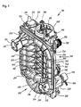
- Fig. 1 shows a hydraulic module 100 with a flow port 220, a first return port 210 and an alternative second return port 320.
- the first return port 210 has a stop 211 and a first port contour 212. Furthermore, a 3/2-way valve is provided.
- the hydraulic module consists of a first wall 200 and a second wall 300.
- the first wall 200 has a first conduit wall 201 of a conduit inlet 230, and a second conduit wall 202 of a conduit outlet 240.
- the first conduit wall 201 has an angled portion with a radius the bend is executed approximately at right angles.
- the line inlet 230 leads to a cavity 160. From the cavity 160, the line outlet 240 leads to the first return connection 210 and to the second return connection 320.
- the cavity 160 has a first outer wall 260.
- Return port 210 and the second return port 320 are each configured with an outer contour 221 for a securing element, for example a security wire.
- a base surface 223 is provided, on which there is, so to speak, the flow connection 220, which is integrally integrated into the hydraulic module.
- different ribs are attached to the first wall, for example, there is a rib 205, a longitudinal rib 209 and other ribs. These ribs have in common that they contribute to the strengthening and stiffening of the hydraulic module.
- a rib ring 207 a total of six ribs run together in the exemplary embodiment.
- the hydraulic module has a first web 250 for a welding flange.
- a tab 270 is provided with a mounting hole 271.
- a volumetric flow sensor 341 with a clamp 342 is held on a sensor receptacle 340.
- a servomotor 332 is mounted with connecting leads 333.
- the valve drive 332 opens the flow either through the first return port 210 or the second return port 320.
- a flange 390 with a pipe 391 is provided for a safety valve 392 with a knob 393.
- a heating flange 400 is introduced in the cavity 160.
- This heating flange 400 is fastened with a fastening ring 430 on the hydraulic module by means of fastening screws 440.
- a protective conductor tab 420 with a bore 421 is attached to the heating flange 400.
- the automatic ventilator 372 is connected to the hydraulic module 100 by means of a securing clamp 371 and secured thereto.
- the automatic air vent has a screw cap 374.
- first wall 200 is configured with stiffening ribs 206, of which partially four stiffening ribs and two longitudinal ribs 209 run on a rib ring 207 and are connected thereto.
- the rib ring 207 serves to receive forces that act on the rib ring from the stiffening ribs 206 and the longitudinal ribs 209. With the rib ring 207 in particular voltages are reduced. In particular, if less than six ribs, z. B. four ribs run to a point and are connected to a rib node 208 is provided there.
- the flow connection 22 0 has a Auskemung 224 to avoid accumulation of material in the plastic part.
- the second return connection 320 has a second connection contour 321. Standing up in the area of the heating flange 400, the connection spades 411 of the heating flange 400 are attached.
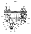
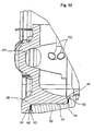
- second wall shows the integration of various components.
- a drainage flange 310 which has a second 1/4 rotary nut 311 with which a sealing plug 312 is fixed in the drainage flange 310.
- the first web 250 of the welding flange is below the drainage flange.
- the second wall 300 has various stiffening ribs 306 and others as shown in the figure.
- a mirror 305 is provided, to which the article identification and serial number and the like can be applied as a sticker, imprint or embossing.
- the second wall 300 forms a third conduit wall 301 of the conduit inlet 230 and a fourth conduit wall for the conduit outlet 240.
- a second outer wall 360 of the cavity 160 is formed.
- connection 350 for an additional measurement technique is provided in the second outer wall 360.
- This port if not used for additional metrology, is also sealed with a sealing plug 312 secured with a 1/4 turn nut 311.
- this connection is permanently closed by spraying with plastic material.
- the servomotor 332 with its connection lines 333 is fastened to the hydraulic module 100 by means of servomotor screws 334.
- the valve drive 330 is fastened in particular to a valve seat 331.
- the guide tube 380 for a temperature sensor is sealed in the embodiment with a plug 381 which is fixed with a first 1/4 rotary nut 382, watertight.
- the safety valve 392 is held in the flange 390 with a securing bracket 394.
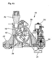
- FIG. 4a shown hydraulic module shows the heating flange 400 with a plurality of tubular heating elements 410. These are shown with corresponding connection spade 411 in the form of a blade receptacle or a screw eye or other attachment for electrical connections.
- the fastening ring 430 for fastening the heating flange 400 in the hydraulic module 100 has three struts 431, which run onto a ring 433 in the middle of the fastening ring 430.
- the ring 433 has an annular hole 432 for a sensor pebble, eg a temperature sensor or safety temperature limiter.
- the sensor bulb not shown, is through pushed the ring 433 in a protective tube 436, which is located behind the ring hole 432.
- the hydraulic module 100 has further stiffeners 225, e.g. Support the flow connection 220 and other connections.
- the first wall 200 and the second wall 300 have a common welding surface 110 or a so-called welding flange.
- the flange 390 is provided with a pipe piece 391 for the safety valve 392.
- the pipe section 391 is in the embodiment, a one-story extension of the flange 390th
- the flange 390 for the safety valve 392 has a drain port 395.
- the first wall 200 and the second wall 300 are joined together at the welding surface 110, and an edge 120 of the mold separation can be seen.
- the protective conductor tab 420 has a bore 421 for attachment of a protective conductor.
- the hydraulic module 100 is shown with a first welding flange 111.
- the first welding flange is formed by a welding surface 203 of the first wall 200 and by a second welding surface 303 of the second wall 300.
- a first cavity 112 is formed by the boundary with a first catching rib 113.
- a second welding flange 114 is formed between a third welding surface 204 and a fourth welding surface 304.
- a second cavity 115 is provided into which, for example, welding material can be displaced.
- the second cavity 115 is bounded by a second catching rib 116.
- a center cavity 117 is arranged, which is also provided for receiving welding material and for tolerance compensation of the first wall 200 to the second wall 300 and the welding amplitude, the vibration welding in a direction up to 1 mm, ensure.
- the drainage flange 310 is sealed with an O-ring 313.
- In the cavity 160 at least one tubular heater 410 is arranged.
- a float chamber 150 is arranged with a highest point 151, here air can be discharged with the automatic bleeder 370 from the hydraulic module 100.
- the float chamber 150 and the highest point 151 are connected via an opening 140 to the heating flow 130.
- the heating flange according to Fig. 8 has a plurality of tubular heating elements 410, which have a connection spade 411 or a screw eye.
- the fastening ring 430, the struts 431, points to the struts 431 in the embodiment at least one cable hook 434 and at least one cable web 435. With the cable hook 434 and the cable web 435 in particular electrical connection lines or sensor capillary can be held on the struts 431.
- Wings 437 are used to attach the mounting ring 430 on the hydraulic module 100, whereby the heating flange 400 is held in the hydraulic module.
- a section through the heating flange 400 is shown.
- the tubular heater 410 shown in section has a radiator pin 414, to which the connection spades 411 can be attached.
- the tubular heating element 410 is internally filled with a MgO insulation 413 and provided with a closure 412.
- a protective tube 436 is attached, which is connected in a watertight and pressure-tight manner with the heating flange. It is open to the ring hole 432 whereby a sensor bulb, for example, a temperature sensor can be inserted through the ring hole 432 in the protective tube 436.
- a catch hook or a similar connection for adapting and fixing a sensor bulb is still provided on the heating flange 400.
- the line feed 240 which is in Fig. 10 is shown leads into the cavity 160, in which the tubular heating elements 410 are located. Furthermore, the first welding flange 111 and the second welding flange 114 are shown.
- the sealing plug 312 is shown for the drainage flange. It has a hook 3121 for latching.
- the sealing plug is formed by a ring cover 3122, which has a web ring 3123, a stub ring 3124 and a cavity 3125. Furthermore, a pin 3126 is provided. This is the same snap hook as 3121, only in a different view.
- the plug has a total of four evenly distributed over the circumference.
- the seal is made in the embodiment with a fourth O-ring 313rd
- Fig. 12 shows how a pipe 500, in particular copper pipe, in a first return port 210, a flow port 220 and / or a second return port 320 is inserted.
- the tube 500 has a brass fitting 501, which is fastened to the tube 500 with a solder connection 502.
- a fifth O-ring 505 is inserted for sealing.
- the pipe 500 which may be a flow or return pipe of a heat pump, is attached and secured to the first return port 320, the forward port 220, or the second return port 320 with a backup wire 222.
- the fuse wire 222 is advantageously universal for all terminals and Additional components can be used for securing. Alternatively, a fastening hook, a screw or the like may be used.
- Fig. 13 shows a heat pump 10 with a frame 11.
- a refrigerant circuit 60 having a compressor 61, a condenser 62, an evaporator 63, an expansion valve 64, a sight glass 65, a dryer 66, a suction line 67 and a hot gas line 68 is shown
- an expansion tank 50 for the heating and an expansion tank 53 for the heat source are provided in the upper part of the frame.
- the expansion tank 50 for the heater is coupled to a first vibration damper 51 of the heat pump 10.
- a cap valve 52 is connected to the expansion tank 53 of the heat source.
- a second vibration damper 54 is attached to the expansion tank 53 of the heat source.
- the hydraulic module 100 is connected to a first return port 210 of the hydraulic module 100 at a return line, not shown, and the feed line (not shown) of the heat pump is connected to a flow port 220 of the hydraulic module 100. Furthermore, the heat pump still has a flow pump 40 for the brine and a flow pump 31 for the heating and hot water.
- the hydraulic module 100 is equipped with at least one temperature sensor 71, which is connectable to a not shown control of the heat pump. Also connected to the regulator is the valve drive 332, with which the quantities of water are controlled by the hydraulic module 100 and / or the flow through the heating or the hot water system. Furthermore, the at least one tubular heater 410 of the heating flange 400 of the hydraulic module 100 is connected to a switching device or is controlled by the controller. To connect a heater and a hot water system, not shown, the heat pump 10 lines 43 for hot water and heating. Lines 42 are provided for the brine connection of the heat source.
- the evaporator In an air / water heat pump, the evaporator is flowed through by an air flow, which gives off heat to the evaporator flowing through the refrigerant. Therefore, the evaporator of an air heat pump is usually mounted in another room where the air flows as a heat source.
- a brine / water heat pump is shown, in which a brine, which usually absorbs heat from the soil, is provided as the heat source. The brine flows through here in the same room mounted evaporator 63.
Landscapes
- Engineering & Computer Science (AREA)
- Physics & Mathematics (AREA)
- Thermal Sciences (AREA)
- Chemical & Material Sciences (AREA)
- Combustion & Propulsion (AREA)
- Mechanical Engineering (AREA)
- General Engineering & Computer Science (AREA)
- Steam Or Hot-Water Central Heating Systems (AREA)
Applications Claiming Priority (1)
| Application Number | Priority Date | Filing Date | Title |
|---|---|---|---|
| DE102009048585A DE102009048585A1 (de) | 2009-10-07 | 2009-10-07 | Hydraulikmodul für ein Haustechnikgerät und Wärmepumpe mit einem Hydraulikmodul |
Publications (3)
| Publication Number | Publication Date |
|---|---|
| EP2312224A2 true EP2312224A2 (fr) | 2011-04-20 |
| EP2312224A3 EP2312224A3 (fr) | 2014-12-03 |
| EP2312224B1 EP2312224B1 (fr) | 2019-12-25 |
Family
ID=43127794
Family Applications (1)
| Application Number | Title | Priority Date | Filing Date |
|---|---|---|---|
| EP10010486.8A Active EP2312224B1 (fr) | 2009-10-07 | 2010-09-24 | Pompe à chaleur dotée d'un module hydraulique |
Country Status (2)
| Country | Link |
|---|---|
| EP (1) | EP2312224B1 (fr) |
| DE (1) | DE102009048585A1 (fr) |
Cited By (5)
| Publication number | Priority date | Publication date | Assignee | Title |
|---|---|---|---|---|
| WO2014005703A3 (fr) * | 2012-07-06 | 2014-09-25 | Stiebel Eltron Gmbh & Co. Kg | Bloc de chauffe |
| EP4089303A1 (fr) | 2021-05-14 | 2022-11-16 | Stiebel Eltron GmbH & Co. KG | Soupape à 3/2 voies, module hydraulique et pompe à chaleur associée |
| EP4542130A1 (fr) * | 2023-10-20 | 2025-04-23 | Stiebel Eltron GmbH & Co. KG | Unité de chauffage domestique |
| EP4614076A1 (fr) * | 2024-03-07 | 2025-09-10 | OTMA S.r.l. con unico socio | Ensemble hydraulique pour une pompe à chaleur pour le chauffage de locaux et/ou pour la production d'eau chaude sanitaire et pompe à chaleur équipée de cet ensemble |
| PL449836A1 (pl) * | 2024-09-16 | 2026-03-23 | Sunex Spółka Akcyjna | Szafa hydrauliczna układu grzewczego |
Families Citing this family (11)
| Publication number | Priority date | Publication date | Assignee | Title |
|---|---|---|---|---|
| CN103206739A (zh) * | 2012-01-11 | 2013-07-17 | 江苏心日源建筑节能科技有限公司 | 地源热泵机组专用水力模块及其操作方法 |
| DE202014002655U1 (de) | 2014-03-27 | 2015-06-30 | Stiebel Eltron Gmbh & Co. Kg | Wärmeenergiesystem mit einem Wärmeerzeuger und einem Behälter |
| EP3553410B1 (fr) | 2018-03-30 | 2023-03-22 | Bosch Termoteknik Isitma ve Klima Sanayi Ticaret Anonim Sirketi | Chauffe-eau |
| SK9474Y1 (sk) | 2021-06-13 | 2022-04-13 | Protherm Production S.R.O. | Hydraulický modul pre vykurovacie zariadenie s tepelným čerpadlom |
| CN115523524A (zh) * | 2021-06-24 | 2022-12-27 | 丹佛斯有限公司 | 模块化供暖站 |
| IT202300000459A1 (it) * | 2023-01-16 | 2024-07-16 | Ariston Spa | Sistema a pompa di calore comprendente un dispositivo degasatore ed un riscaldatore di riserva |
| CN120604087A (zh) | 2023-01-31 | 2025-09-05 | 格兰富控股公司 | 用于热泵的集成水回路 |
| EP4603759A1 (fr) | 2024-02-15 | 2025-08-20 | BDR Thermea Group B.V. | Dispositif de chauffage et système de pompe à chaleur |
| DE202024101469U1 (de) | 2024-03-25 | 2024-04-04 | Reflex Winkelmann Gmbh | Hydraulikmodul für wasserführende Systeme |
| DE102024128468A1 (de) | 2024-10-01 | 2026-04-02 | Stiebel Eltron Gmbh & Co. Kg | Haustechnik-Rücklaufsammler |
| DE102024128467A1 (de) | 2024-10-01 | 2026-04-02 | Stiebel Eltron Gmbh & Co. Kg | Wärmepumpen-Hydraulikeinheit und Hydraulikverteiler |
Citations (5)
| Publication number | Priority date | Publication date | Assignee | Title |
|---|---|---|---|---|
| DE3214775A1 (de) | 1982-04-21 | 1983-11-10 | IWK Regler und Kompensatoren GmbH, 7513 Stutensee | Vorrichtung zum uebergeben von waerme von einer versorgungsleitung zu einem abnehmer |
| EP1447627B1 (fr) | 2003-02-07 | 2008-04-30 | IMMOSOLAR Vertriebs GmbH | Dispositif de commande et/ou contrôle d'un chauffage ou d'un refroidissement d'un immeuble |
| DE202008003241U1 (de) | 2008-03-07 | 2008-05-08 | Zehnder Verkaufs- Und Verwaltungs Ag | Vorrichtung geeignet für ein Wärmemanagementsystem eines Raums |
| EP1528330B1 (fr) | 2003-11-03 | 2008-06-04 | Grundfos A/S | Ensemble pour installation de chauffage compact |
| EP1884723B1 (fr) | 2006-07-28 | 2008-08-20 | Grundfos Management A/S | Module |
Family Cites Families (10)
| Publication number | Priority date | Publication date | Assignee | Title |
|---|---|---|---|---|
| GB767847A (en) * | 1954-07-05 | 1957-02-06 | Brentford Electric Ltd. | Improvements in or relating to combined refrigerating and water heating systems |
| DE3306232A1 (de) * | 1983-02-23 | 1984-08-23 | Fichtel & Sachs Ag, 8720 Schweinfurt | Baueinheit aus kondensator, sammler und fluessigkeitsabscheider fuer eine waermepumpe |
| DE3817441A1 (de) * | 1988-05-21 | 1989-11-23 | Eckerfeld Erika | Elektrischer durchlauferhitzer |
| FR2755752B1 (fr) * | 1996-11-08 | 1999-02-05 | Aries | Module hydraulique pour installation de chauffage central et de production d'eau chaude, et chaudiere equipee d'un tel module |
| DE29719717U1 (de) * | 1997-11-06 | 1999-04-01 | Viessmann Werke GmbH & Co., 35108 Allendorf | Wärmepumpentherme |
| DE19820818C2 (de) * | 1998-05-09 | 2002-12-05 | Viessmann Werke Kg | Wärmepumpe |
| DE19909780A1 (de) * | 1999-03-05 | 2000-09-07 | Weishaupt Max Gmbh | Armaturenmodul für ein Heizungs- und/oder Warmwasserleitungssystem eines Gebäudes |
| DE10063851A1 (de) * | 2000-12-21 | 2002-07-04 | Stiebel Eltron Gmbh & Co Kg | Elektrischer Durchlauferhitzer |
| DE20103392U1 (de) * | 2001-02-27 | 2002-01-03 | Viessmann Werke GmbH & Co., 35108 Allendorf | Heizkreisverteiler |
| DE20104615U1 (de) * | 2001-03-16 | 2001-05-17 | Gebr. Tuxhorn GmbH & Co. KG, 33647 Bielefeld | Baugruppe für ein Heizungssystem |
-
2009
- 2009-10-07 DE DE102009048585A patent/DE102009048585A1/de active Pending
-
2010
- 2010-09-24 EP EP10010486.8A patent/EP2312224B1/fr active Active
Patent Citations (5)
| Publication number | Priority date | Publication date | Assignee | Title |
|---|---|---|---|---|
| DE3214775A1 (de) | 1982-04-21 | 1983-11-10 | IWK Regler und Kompensatoren GmbH, 7513 Stutensee | Vorrichtung zum uebergeben von waerme von einer versorgungsleitung zu einem abnehmer |
| EP1447627B1 (fr) | 2003-02-07 | 2008-04-30 | IMMOSOLAR Vertriebs GmbH | Dispositif de commande et/ou contrôle d'un chauffage ou d'un refroidissement d'un immeuble |
| EP1528330B1 (fr) | 2003-11-03 | 2008-06-04 | Grundfos A/S | Ensemble pour installation de chauffage compact |
| EP1884723B1 (fr) | 2006-07-28 | 2008-08-20 | Grundfos Management A/S | Module |
| DE202008003241U1 (de) | 2008-03-07 | 2008-05-08 | Zehnder Verkaufs- Und Verwaltungs Ag | Vorrichtung geeignet für ein Wärmemanagementsystem eines Raums |
Cited By (9)
| Publication number | Priority date | Publication date | Assignee | Title |
|---|---|---|---|---|
| WO2014005703A3 (fr) * | 2012-07-06 | 2014-09-25 | Stiebel Eltron Gmbh & Co. Kg | Bloc de chauffe |
| CN104428604A (zh) * | 2012-07-06 | 2015-03-18 | 斯德宝公司 | 加热块 |
| GB2519039A (en) * | 2012-07-06 | 2015-04-08 | Stiebel Eltron Gmbh & Co Kg | Heating block |
| US9709299B2 (en) | 2012-07-06 | 2017-07-18 | Stiebel Eltron Gmbh & Co. Kg | Heating block |
| EP4089303A1 (fr) | 2021-05-14 | 2022-11-16 | Stiebel Eltron GmbH & Co. KG | Soupape à 3/2 voies, module hydraulique et pompe à chaleur associée |
| DE102021112551A1 (de) | 2021-05-14 | 2022-11-17 | Stiebel Eltron Gmbh & Co. Kg | 3/2-Wegeventil, Hydraulikbaugruppe und zugehörige Wärmepumpe |
| EP4542130A1 (fr) * | 2023-10-20 | 2025-04-23 | Stiebel Eltron GmbH & Co. KG | Unité de chauffage domestique |
| EP4614076A1 (fr) * | 2024-03-07 | 2025-09-10 | OTMA S.r.l. con unico socio | Ensemble hydraulique pour une pompe à chaleur pour le chauffage de locaux et/ou pour la production d'eau chaude sanitaire et pompe à chaleur équipée de cet ensemble |
| PL449836A1 (pl) * | 2024-09-16 | 2026-03-23 | Sunex Spółka Akcyjna | Szafa hydrauliczna układu grzewczego |
Also Published As
| Publication number | Publication date |
|---|---|
| DE102009048585A1 (de) | 2011-04-14 |
| EP2312224B1 (fr) | 2019-12-25 |
| EP2312224A3 (fr) | 2014-12-03 |
Similar Documents
| Publication | Publication Date | Title |
|---|---|---|
| EP2312224B1 (fr) | Pompe à chaleur dotée d'un module hydraulique | |
| EP3648997A1 (fr) | Installation frigorifique pour véhicule pourvue d'un circuit de réfrigération équipé d'un échangeur thermique et échangeur thermique conçu pour une telle installation frigorifique | |
| DE202009001056U1 (de) | Heizkreisverteiler | |
| EP4050269B1 (fr) | Dispositif de chauffage, système de chauffage et procédé | |
| DE102006013271B4 (de) | Kondensatverdunster | |
| DE102016115824A1 (de) | System zum Anordnen von Vorrichtungen zum Temperieren eines Wärmeträgerfluids in einem Wärmeträgerkreislauf und Verfahren zum Betreiben des Systems | |
| EP1529470A1 (fr) | Module de chauffage avec surface chauffante et chaudière instantanée et procédé pour sa fabrication | |
| DE102008057495A1 (de) | Wärmespeicheranordnung | |
| CH708598A1 (de) | Anordnung und Verfahren zum Raumtemperieren und Warmwasserbereitstellen. | |
| EP1884720B1 (fr) | Ensemble pour installation de chauffage compact | |
| DE202011004012U1 (de) | Haustechnikgerät zur Aufstellung in einem Gebäude mit einer Kombination aus einer Wärmepumpe und einem Lüftungsteil | |
| EP2053951B1 (fr) | Chauffe-eau, en particulier pour une machine à café | |
| EP0630463B2 (fr) | Chauffe-eau electrique instantane | |
| DE102009051209A1 (de) | Einrichtung zur Temperaturregelung eines Raumes mit mindestens einer mit einem Wärmeträger betriebenen Heizeinrichtung | |
| DE102014000671B4 (de) | Solaranlage und Verfahren zum Betreiben einer solchen | |
| DE102012004232A1 (de) | Haustechnikgerät zur Aufstellung in einem Gebäude mit einer Kombination aus einer Wärmepumpe und einem Lüftungsteil | |
| EP4025841B1 (fr) | Dispositif de retenue destiné à retenir un capteur de mesure et à transmettre un signal de mesure électrique | |
| EP1884723B1 (fr) | Module | |
| EP2530409A2 (fr) | Installation de pompe à chaleur et procédé de fonctionnement dýune installation de pompe à chaleur | |
| EP2056039A1 (fr) | Système de collecteur solaire | |
| EP1528371B1 (fr) | Ensemble pour installation de chauffage compact | |
| AT505444A2 (de) | Fixierung eines solarabsorberrohres in einem rahmen | |
| EP2570881B2 (fr) | Dispositif de régulation de température, en particulier un dispositif thermostatique | |
| EP1014005A2 (fr) | Appareil pour l'installation de chauffage avec une vase de découplage et avec distributeur de circuit de chauffage | |
| DE202014002654U1 (de) | Haustechnikgerät mit einem Abschluss für einen Energiewandler |
Legal Events
| Date | Code | Title | Description |
|---|---|---|---|
| PUAI | Public reference made under article 153(3) epc to a published international application that has entered the european phase |
Free format text: ORIGINAL CODE: 0009012 |
|
| AK | Designated contracting states |
Kind code of ref document: A2 Designated state(s): AL AT BE BG CH CY CZ DE DK EE ES FI FR GB GR HR HU IE IS IT LI LT LU LV MC MK MT NL NO PL PT RO SE SI SK SM TR |
|
| AX | Request for extension of the european patent |
Extension state: BA ME RS |
|
| PUAL | Search report despatched |
Free format text: ORIGINAL CODE: 0009013 |
|
| AK | Designated contracting states |
Kind code of ref document: A3 Designated state(s): AL AT BE BG CH CY CZ DE DK EE ES FI FR GB GR HR HU IE IS IT LI LT LU LV MC MK MT NL NO PL PT RO SE SI SK SM TR |
|
| AX | Request for extension of the european patent |
Extension state: BA ME RS |
|
| RIC1 | Information provided on ipc code assigned before grant |
Ipc: F24H 9/14 20060101ALI20141029BHEP Ipc: F24D 3/18 20060101AFI20141029BHEP Ipc: F24D 19/08 20060101ALI20141029BHEP Ipc: F24H 1/12 20060101ALI20141029BHEP |
|
| 17P | Request for examination filed |
Effective date: 20150603 |
|
| RBV | Designated contracting states (corrected) |
Designated state(s): AL AT BE BG CH CY CZ DE DK EE ES FI FR GB GR HR HU IE IS IT LI LT LU LV MC MK MT NL NO PL PT RO SE SI SK SM TR |
|
| 17Q | First examination report despatched |
Effective date: 20160324 |
|
| STAA | Information on the status of an ep patent application or granted ep patent |
Free format text: STATUS: EXAMINATION IS IN PROGRESS |
|
| GRAP | Despatch of communication of intention to grant a patent |
Free format text: ORIGINAL CODE: EPIDOSNIGR1 |
|
| STAA | Information on the status of an ep patent application or granted ep patent |
Free format text: STATUS: GRANT OF PATENT IS INTENDED |
|
| INTG | Intention to grant announced |
Effective date: 20190708 |
|
| GRAS | Grant fee paid |
Free format text: ORIGINAL CODE: EPIDOSNIGR3 |
|
| GRAF | Information related to payment of grant fee modified |
Free format text: ORIGINAL CODE: EPIDOSCIGR3 |
|
| GRAA | (expected) grant |
Free format text: ORIGINAL CODE: 0009210 |
|
| STAA | Information on the status of an ep patent application or granted ep patent |
Free format text: STATUS: THE PATENT HAS BEEN GRANTED |
|
| AK | Designated contracting states |
Kind code of ref document: B1 Designated state(s): AL AT BE BG CH CY CZ DE DK EE ES FI FR GB GR HR HU IE IS IT LI LT LU LV MC MK MT NL NO PL PT RO SE SI SK SM TR |
|
| REG | Reference to a national code |
Ref country code: GB Ref legal event code: FG4D Free format text: NOT ENGLISH |
|
| REG | Reference to a national code |
Ref country code: CH Ref legal event code: NV Representative=s name: BOHEST AG, CH Ref country code: CH Ref legal event code: EP |
|
| REG | Reference to a national code |
Ref country code: DE Ref legal event code: R096 Ref document number: 502010016422 Country of ref document: DE |
|
| REG | Reference to a national code |
Ref country code: AT Ref legal event code: REF Ref document number: 1217520 Country of ref document: AT Kind code of ref document: T Effective date: 20200115 |
|
| REG | Reference to a national code |
Ref country code: IE Ref legal event code: FG4D Free format text: LANGUAGE OF EP DOCUMENT: GERMAN |
|
| REG | Reference to a national code |
Ref country code: SE Ref legal event code: TRGR |
|
| REG | Reference to a national code |
Ref country code: NL Ref legal event code: MP Effective date: 20191225 |
|
| PG25 | Lapsed in a contracting state [announced via postgrant information from national office to epo] |
Ref country code: LT Free format text: LAPSE BECAUSE OF FAILURE TO SUBMIT A TRANSLATION OF THE DESCRIPTION OR TO PAY THE FEE WITHIN THE PRESCRIBED TIME-LIMIT Effective date: 20191225 Ref country code: GR Free format text: LAPSE BECAUSE OF FAILURE TO SUBMIT A TRANSLATION OF THE DESCRIPTION OR TO PAY THE FEE WITHIN THE PRESCRIBED TIME-LIMIT Effective date: 20200326 Ref country code: LV Free format text: LAPSE BECAUSE OF FAILURE TO SUBMIT A TRANSLATION OF THE DESCRIPTION OR TO PAY THE FEE WITHIN THE PRESCRIBED TIME-LIMIT Effective date: 20191225 Ref country code: BG Free format text: LAPSE BECAUSE OF FAILURE TO SUBMIT A TRANSLATION OF THE DESCRIPTION OR TO PAY THE FEE WITHIN THE PRESCRIBED TIME-LIMIT Effective date: 20200325 Ref country code: FI Free format text: LAPSE BECAUSE OF FAILURE TO SUBMIT A TRANSLATION OF THE DESCRIPTION OR TO PAY THE FEE WITHIN THE PRESCRIBED TIME-LIMIT Effective date: 20191225 Ref country code: NO Free format text: LAPSE BECAUSE OF FAILURE TO SUBMIT A TRANSLATION OF THE DESCRIPTION OR TO PAY THE FEE WITHIN THE PRESCRIBED TIME-LIMIT Effective date: 20200325 |
|
| REG | Reference to a national code |
Ref country code: LT Ref legal event code: MG4D |
|
| PG25 | Lapsed in a contracting state [announced via postgrant information from national office to epo] |
Ref country code: HR Free format text: LAPSE BECAUSE OF FAILURE TO SUBMIT A TRANSLATION OF THE DESCRIPTION OR TO PAY THE FEE WITHIN THE PRESCRIBED TIME-LIMIT Effective date: 20191225 |
|
| PG25 | Lapsed in a contracting state [announced via postgrant information from national office to epo] |
Ref country code: AL Free format text: LAPSE BECAUSE OF FAILURE TO SUBMIT A TRANSLATION OF THE DESCRIPTION OR TO PAY THE FEE WITHIN THE PRESCRIBED TIME-LIMIT Effective date: 20191225 |
|
| PG25 | Lapsed in a contracting state [announced via postgrant information from national office to epo] |
Ref country code: CZ Free format text: LAPSE BECAUSE OF FAILURE TO SUBMIT A TRANSLATION OF THE DESCRIPTION OR TO PAY THE FEE WITHIN THE PRESCRIBED TIME-LIMIT Effective date: 20191225 Ref country code: PT Free format text: LAPSE BECAUSE OF FAILURE TO SUBMIT A TRANSLATION OF THE DESCRIPTION OR TO PAY THE FEE WITHIN THE PRESCRIBED TIME-LIMIT Effective date: 20200520 Ref country code: RO Free format text: LAPSE BECAUSE OF FAILURE TO SUBMIT A TRANSLATION OF THE DESCRIPTION OR TO PAY THE FEE WITHIN THE PRESCRIBED TIME-LIMIT Effective date: 20191225 Ref country code: NL Free format text: LAPSE BECAUSE OF FAILURE TO SUBMIT A TRANSLATION OF THE DESCRIPTION OR TO PAY THE FEE WITHIN THE PRESCRIBED TIME-LIMIT Effective date: 20191225 Ref country code: EE Free format text: LAPSE BECAUSE OF FAILURE TO SUBMIT A TRANSLATION OF THE DESCRIPTION OR TO PAY THE FEE WITHIN THE PRESCRIBED TIME-LIMIT Effective date: 20191225 |
|
| PG25 | Lapsed in a contracting state [announced via postgrant information from national office to epo] |
Ref country code: SK Free format text: LAPSE BECAUSE OF FAILURE TO SUBMIT A TRANSLATION OF THE DESCRIPTION OR TO PAY THE FEE WITHIN THE PRESCRIBED TIME-LIMIT Effective date: 20191225 Ref country code: IS Free format text: LAPSE BECAUSE OF FAILURE TO SUBMIT A TRANSLATION OF THE DESCRIPTION OR TO PAY THE FEE WITHIN THE PRESCRIBED TIME-LIMIT Effective date: 20200425 Ref country code: SM Free format text: LAPSE BECAUSE OF FAILURE TO SUBMIT A TRANSLATION OF THE DESCRIPTION OR TO PAY THE FEE WITHIN THE PRESCRIBED TIME-LIMIT Effective date: 20191225 |
|
| REG | Reference to a national code |
Ref country code: DE Ref legal event code: R097 Ref document number: 502010016422 Country of ref document: DE |
|
| PG25 | Lapsed in a contracting state [announced via postgrant information from national office to epo] |
Ref country code: ES Free format text: LAPSE BECAUSE OF FAILURE TO SUBMIT A TRANSLATION OF THE DESCRIPTION OR TO PAY THE FEE WITHIN THE PRESCRIBED TIME-LIMIT Effective date: 20191225 Ref country code: DK Free format text: LAPSE BECAUSE OF FAILURE TO SUBMIT A TRANSLATION OF THE DESCRIPTION OR TO PAY THE FEE WITHIN THE PRESCRIBED TIME-LIMIT Effective date: 20191225 |
|
| PLBE | No opposition filed within time limit |
Free format text: ORIGINAL CODE: 0009261 |
|
| STAA | Information on the status of an ep patent application or granted ep patent |
Free format text: STATUS: NO OPPOSITION FILED WITHIN TIME LIMIT |
|
| PG25 | Lapsed in a contracting state [announced via postgrant information from national office to epo] |
Ref country code: SI Free format text: LAPSE BECAUSE OF FAILURE TO SUBMIT A TRANSLATION OF THE DESCRIPTION OR TO PAY THE FEE WITHIN THE PRESCRIBED TIME-LIMIT Effective date: 20191225 |
|
| 26N | No opposition filed |
Effective date: 20200928 |
|
| PG25 | Lapsed in a contracting state [announced via postgrant information from national office to epo] |
Ref country code: IT Free format text: LAPSE BECAUSE OF FAILURE TO SUBMIT A TRANSLATION OF THE DESCRIPTION OR TO PAY THE FEE WITHIN THE PRESCRIBED TIME-LIMIT Effective date: 20191225 |
|
| PG25 | Lapsed in a contracting state [announced via postgrant information from national office to epo] |
Ref country code: PL Free format text: LAPSE BECAUSE OF FAILURE TO SUBMIT A TRANSLATION OF THE DESCRIPTION OR TO PAY THE FEE WITHIN THE PRESCRIBED TIME-LIMIT Effective date: 20191225 |
|
| PG25 | Lapsed in a contracting state [announced via postgrant information from national office to epo] |
Ref country code: MC Free format text: LAPSE BECAUSE OF FAILURE TO SUBMIT A TRANSLATION OF THE DESCRIPTION OR TO PAY THE FEE WITHIN THE PRESCRIBED TIME-LIMIT Effective date: 20191225 |
|
| GBPC | Gb: european patent ceased through non-payment of renewal fee |
Effective date: 20200924 |
|
| REG | Reference to a national code |
Ref country code: BE Ref legal event code: MM Effective date: 20200930 |
|
| PG25 | Lapsed in a contracting state [announced via postgrant information from national office to epo] |
Ref country code: LU Free format text: LAPSE BECAUSE OF NON-PAYMENT OF DUE FEES Effective date: 20200924 |
|
| PG25 | Lapsed in a contracting state [announced via postgrant information from national office to epo] |
Ref country code: FR Free format text: LAPSE BECAUSE OF NON-PAYMENT OF DUE FEES Effective date: 20200930 |
|
| PG25 | Lapsed in a contracting state [announced via postgrant information from national office to epo] |
Ref country code: IE Free format text: LAPSE BECAUSE OF NON-PAYMENT OF DUE FEES Effective date: 20200924 Ref country code: GB Free format text: LAPSE BECAUSE OF NON-PAYMENT OF DUE FEES Effective date: 20200924 Ref country code: BE Free format text: LAPSE BECAUSE OF NON-PAYMENT OF DUE FEES Effective date: 20200930 |
|
| PG25 | Lapsed in a contracting state [announced via postgrant information from national office to epo] |
Ref country code: TR Free format text: LAPSE BECAUSE OF FAILURE TO SUBMIT A TRANSLATION OF THE DESCRIPTION OR TO PAY THE FEE WITHIN THE PRESCRIBED TIME-LIMIT Effective date: 20191225 Ref country code: MT Free format text: LAPSE BECAUSE OF FAILURE TO SUBMIT A TRANSLATION OF THE DESCRIPTION OR TO PAY THE FEE WITHIN THE PRESCRIBED TIME-LIMIT Effective date: 20191225 Ref country code: CY Free format text: LAPSE BECAUSE OF FAILURE TO SUBMIT A TRANSLATION OF THE DESCRIPTION OR TO PAY THE FEE WITHIN THE PRESCRIBED TIME-LIMIT Effective date: 20191225 |
|
| PG25 | Lapsed in a contracting state [announced via postgrant information from national office to epo] |
Ref country code: MK Free format text: LAPSE BECAUSE OF FAILURE TO SUBMIT A TRANSLATION OF THE DESCRIPTION OR TO PAY THE FEE WITHIN THE PRESCRIBED TIME-LIMIT Effective date: 20191225 |
|
| P01 | Opt-out of the competence of the unified patent court (upc) registered |
Effective date: 20230519 |
|
| REG | Reference to a national code |
Ref country code: CH Ref legal event code: U11 Free format text: ST27 STATUS EVENT CODE: U-0-0-U10-U11 (AS PROVIDED BY THE NATIONAL OFFICE) Effective date: 20251001 |
|
| PGFP | Annual fee paid to national office [announced via postgrant information from national office to epo] |
Ref country code: DE Payment date: 20250919 Year of fee payment: 16 |
|
| PGFP | Annual fee paid to national office [announced via postgrant information from national office to epo] |
Ref country code: AT Payment date: 20250919 Year of fee payment: 16 |
|
| PGFP | Annual fee paid to national office [announced via postgrant information from national office to epo] |
Ref country code: SE Payment date: 20250918 Year of fee payment: 16 |
|
| PGFP | Annual fee paid to national office [announced via postgrant information from national office to epo] |
Ref country code: CH Payment date: 20251001 Year of fee payment: 16 |