EP2312236A2 - Verbindungsvorrichtung für eine Ständerkonstruktion - Google Patents
Verbindungsvorrichtung für eine Ständerkonstruktion Download PDFInfo
- Publication number
- EP2312236A2 EP2312236A2 EP10174669A EP10174669A EP2312236A2 EP 2312236 A2 EP2312236 A2 EP 2312236A2 EP 10174669 A EP10174669 A EP 10174669A EP 10174669 A EP10174669 A EP 10174669A EP 2312236 A2 EP2312236 A2 EP 2312236A2
- Authority
- EP
- European Patent Office
- Prior art keywords
- support
- connecting device
- receiving element
- passage opening
- base element
- Prior art date
- Legal status (The legal status is an assumption and is not a legal conclusion. Google has not performed a legal analysis and makes no representation as to the accuracy of the status listed.)
- Withdrawn
Links
- 238000010276 construction Methods 0.000 claims description 16
- 230000003014 reinforcing effect Effects 0.000 description 2
- 230000007704 transition Effects 0.000 description 2
- 238000004873 anchoring Methods 0.000 description 1
- 238000011161 development Methods 0.000 description 1
- 230000018109 developmental process Effects 0.000 description 1
- 238000009434 installation Methods 0.000 description 1
- 238000004519 manufacturing process Methods 0.000 description 1
Images


Classifications
-
- F—MECHANICAL ENGINEERING; LIGHTING; HEATING; WEAPONS; BLASTING
- F24—HEATING; RANGES; VENTILATING
- F24S—SOLAR HEAT COLLECTORS; SOLAR HEAT SYSTEMS
- F24S25/00—Arrangement of stationary mountings or supports for solar heat collector modules
- F24S25/70—Arrangement of stationary mountings or supports for solar heat collector modules with means for adjusting the final position or orientation of supporting elements in relation to each other or to a mounting surface; with means for compensating mounting tolerances
-
- F—MECHANICAL ENGINEERING; LIGHTING; HEATING; WEAPONS; BLASTING
- F24—HEATING; RANGES; VENTILATING
- F24S—SOLAR HEAT COLLECTORS; SOLAR HEAT SYSTEMS
- F24S25/00—Arrangement of stationary mountings or supports for solar heat collector modules
- F24S25/10—Arrangement of stationary mountings or supports for solar heat collector modules extending in directions away from a supporting surface
- F24S25/12—Arrangement of stationary mountings or supports for solar heat collector modules extending in directions away from a supporting surface using posts in combination with upper profiles
-
- F—MECHANICAL ENGINEERING; LIGHTING; HEATING; WEAPONS; BLASTING
- F24—HEATING; RANGES; VENTILATING
- F24S—SOLAR HEAT COLLECTORS; SOLAR HEAT SYSTEMS
- F24S25/00—Arrangement of stationary mountings or supports for solar heat collector modules
- F24S25/60—Fixation means, e.g. fasteners, specially adapted for supporting solar heat collector modules
- F24S25/65—Fixation means, e.g. fasteners, specially adapted for supporting solar heat collector modules for coupling adjacent supporting elements, e.g. for connecting profiles together
-
- E—FIXED CONSTRUCTIONS
- E04—BUILDING
- E04B—GENERAL BUILDING CONSTRUCTIONS; WALLS, e.g. PARTITIONS; ROOFS; FLOORS; CEILINGS; INSULATION OR OTHER PROTECTION OF BUILDINGS
- E04B1/00—Constructions in general; Structures which are not restricted either to walls, e.g. partitions, or floors or ceilings or roofs
- E04B1/18—Structures comprising elongated load-supporting parts, e.g. columns, girders, skeletons
- E04B1/24—Structures comprising elongated load-supporting parts, e.g. columns, girders, skeletons the supporting parts consisting of metal
- E04B1/2403—Connection details of the elongated load-supporting parts
- E04B2001/2415—Brackets, gussets, joining plates
-
- E—FIXED CONSTRUCTIONS
- E04—BUILDING
- E04B—GENERAL BUILDING CONSTRUCTIONS; WALLS, e.g. PARTITIONS; ROOFS; FLOORS; CEILINGS; INSULATION OR OTHER PROTECTION OF BUILDINGS
- E04B1/00—Constructions in general; Structures which are not restricted either to walls, e.g. partitions, or floors or ceilings or roofs
- E04B1/18—Structures comprising elongated load-supporting parts, e.g. columns, girders, skeletons
- E04B1/24—Structures comprising elongated load-supporting parts, e.g. columns, girders, skeletons the supporting parts consisting of metal
- E04B1/2403—Connection details of the elongated load-supporting parts
- E04B2001/2439—Adjustable connections, e.g. using elongated slots or threaded adjustment elements
-
- Y—GENERAL TAGGING OF NEW TECHNOLOGICAL DEVELOPMENTS; GENERAL TAGGING OF CROSS-SECTIONAL TECHNOLOGIES SPANNING OVER SEVERAL SECTIONS OF THE IPC; TECHNICAL SUBJECTS COVERED BY FORMER USPC CROSS-REFERENCE ART COLLECTIONS [XRACs] AND DIGESTS
- Y02—TECHNOLOGIES OR APPLICATIONS FOR MITIGATION OR ADAPTATION AGAINST CLIMATE CHANGE
- Y02E—REDUCTION OF GREENHOUSE GAS [GHG] EMISSIONS, RELATED TO ENERGY GENERATION, TRANSMISSION OR DISTRIBUTION
- Y02E10/00—Energy generation through renewable energy sources
- Y02E10/40—Solar thermal energy, e.g. solar towers
- Y02E10/47—Mountings or tracking
Definitions
- the invention relates to a connecting device for a stator construction of support profiles and of support profiles, in particular for the arrangement of solar panels, referred to in the preamble of claim 1.
- Art further relates to a stator construction, in particular for the arrangement of solar panels, with such a connection device.
- a stand construction has in or on the ground, z. B. in the ground, anchored support profiles on which a grid of transversely and longitudinally arranged support profiles is provided as a support frame.
- anchored support profiles on which a grid of transversely and longitudinally arranged support profiles is provided as a support frame.
- plate-shaped elements such as solar panels are defined in the desired orientation.
- the support profiles are, for example, mounting rails which can be connected to one another simply by means of correspondingly formed fastening devices and on which the plate-shaped elements can be easily fixed by means of appropriately designed fastening devices. Between the support profiles and individual support profiles connecting devices are provided.
- the support profiles are often rammed into the ground or anchored in the ground for anchoring, so that a vertical alignment after setting the same is not always guaranteed.
- This known connection device has a base element, a receiving element and a locking device, by means of which the receiving element relative to the base element can be fixed thereto.
- the U-shaped base member has two legs as a mounting portion of the base member for placement on a support profile of the stator construction and a support portion connecting the two legs with a receiving member facing the support side.
- the legs of the U-shaped Base element are provided with through openings for screws and nuts having clamping means, which are passed through openings at the end of the corresponding support profile and clamped to fix the base member.
- the receiving element is formed by two L-shaped parts, between which a receptacle for a support profile of the stator construction is formed.
- the flanges of the L-shaped parts each form an abutment section with an attachment side facing the base element.
- the locking device of this connecting device comprises elongated holes, which are arranged in the mounting flanges and extend transversely to the longitudinal extent of the recorded in the recording support profile. Further, in the support portion of the base member with the slots of the mounting flanges can be brought into overlap, transverse to this, d. H. provided in the direction of the longitudinal extension of the recorded in the receiving support profile extending slots. In the intersecting slots each screw with nuts are provided as a clamping means for fixing the receiving element to the base member. After releasing the four clamping means, the receiving element is displaceable relative to the base element.
- a disadvantage of the known solution is that the locking device has a plurality of clamping means, which must be arranged for fixing the receiving element to the base member and each separately braced. Especially in solar parks with a variety of support profiles, this connection device requires a high assembly cost.
- the object of the invention is to provide a connecting device for a stator construction, which does not have the aforementioned disadvantages and in particular allows a simple and flexible mounting of a stator construction.
- the locking device comprises at least one clamping means and at least one bearing means and between the clamping means and the bearing means are provided a contact area and at least one recess area.
- the receiving element In the clamped state of the locking device, the receiving element is flat in the area of the contact area on the base element. In the region of the recess region, the receiving element and the base element are spaced apart from one another by a gap or by an undercut, which results from the at least one depression region. If the at least one clamping device is released, this will tip over Receiving element about the tilting axis, which is formed by the transition portion between the contact area and the recess area. In this state of the connecting device, the receiving element for adjustment relative to the base member is displaceable. If, subsequently, the at least one tensioning means is tensioned again, the receiving element tilts back, so that the receiving element and the base element are again in contact with one another in the area of the contact area. In this state of the connecting device, the receiving element is fixed in the desired orientation relative to the base element.
- a clamping means which is advantageously designed as a clamping screw, and a bearing means, for example, as a clamping screw or as Gariet z. B. is formed with two rivet heads.
- the inventive connecting device has a small number of parts and is therefore particularly economical to produce.
- the at least one clamping means and the at least one bearing means are advantageously provided on the contact section within the receptacle of the receiving element.
- the connecting device is advantageously pre-assembled at the factory and made available to the user in the assembled state.
- no other parts of the connecting device must be carried separately.
- all the bracing means of the connecting device each have the same rotary control means, so that only one type of tool is needed for the assembly and adjustment of the connecting device.
- this is at least one clamping means in the contact area and the at least one bearing means is provided in at least one recess area, whereby a simple adjustment of the receiving element is ensured relative to the base member in the released state of the clamping means.
- a shoulder is provided between the abutment region and the at least one recessed region, which permits a simple design of the tilting axis or of the recessed region on the corresponding element of the connecting device.
- the heel is advantageously in an inclination, which with the plane spanned by the contact area an angle of less than 90 ° and particularly advantageously encloses an angle in the range of 40 ° to 50 °, whereby extreme stress peaks in the material of the corresponding element in the transition region between the recessed area and the contact area are avoided.
- the shoulder is provided on the support side of the support portion of the base member, whereby in the dissolved state of the fixing device, the receiving element is simply displaceable relative to the base member.
- the paragraph is provided on the contact side of the contact portion of the receiving element.
- a shoulder is provided both on the support side of the support section of the base element and on the contact side of the contact section of the receiving element, whereby a particularly large gap between the base member and the receiving element is provided without the material thickness of one of the elements of the connecting device significantly weaknesses.
- the support section of the base element preferably has a fixing section projecting beyond the fastening section on at least one side of the fastening section, and at least part of the locking device is provided in the region of this fixing section.
- the arranged on the at least one side superior fixing portion of the locking device is further accessible from the outside for fixing the receiving element relative to the base member, even if the connecting device is arranged on the support profile.
- the at least one clamping device is provided as part of the locking device in the region of the fixing section.
- the base element has a first passage opening for the at least one tensioning means and a second passage opening for the at least one bearing means in the support section and the receiving element has a first passage opening for the at least one tensioning means and a second passage opening for the at least one bearing means in the contact section at least one of these passage openings is formed as a slot.
- the at least one elongated hole allows easy displaceability in a predefined by the dimensions of the slot predefined area.
- one of the passage openings of an element is formed as a curved extending slot, wherein the radius of the slot corresponds to the distance of the slot to the adjacent passage opening in the corresponding element and wherein the concave longitudinal side of the slot facing this passage opening.
- at least the two through-openings of the receiving element and of the base element, which in the assembled state of the connecting device opposite each other as elongated holes are formed, which overlap crossing each other.
- the first passage opening for the at least one clamping means in the support portion of the base member is formed as a slot, whereby a simple adjustability of the connecting device and the support profile received therein is ensured.
- the first passage opening is designed as a curved elongated hole, wherein the radius of the slot corresponds to the distance of the slot to the second passage opening in the base member and the concave longitudinal side of the slot facing this passage opening.
- the receiving element is pivotable relative to the base element in the released state of the connecting device about a pivot axis formed by the at least one bearing means.
- one of the lead-through openings has a threaded portion for at least one clamping means and / or arranged on at least one bearing means thread, which additionally arranged on Verspannetti, such as.
- Verspanne As nuts, for bracing the at least one clamping means and / or the at least one bearing means can be dispensed with.
- the connecting device has significantly fewer individual parts, making it even easier to handle and economical to manufacture.
- the first passage opening for the at least one threaded clamping means in the contact portion of the receiving element has a threaded portion and the second passage opening for the at least one threaded bearing means in the support portion of the base member has a threaded portion, whereby the connecting device is easy to clamp and detach.
- the receiving element has a fixing device for fixing the support profile accommodated in the receptacle, which comprises a bore and a curved slot extending therefrom.
- the radius of the curved elongated hole advantageously corresponds to the distance of the oblong hole to the bore and the concave longitudinal side of the oblong hole faces this bore.
- the fixing device comprises at least one rear engagement element, which engages in a correspondingly formed on the support profile Schugreifnut and which is pivotable about a guided through the bore clamping means. This allows a simple adjustment of the inclination of the support profile according to the provided pivoting range.
- An inventive stand construction in particular for the arrangement of solar panels, has a plurality of support profiles and a plurality of support profiles, wherein between at least one of the support profiles and at least one of the support profiles, a connection device is provided, which has the aforementioned features.
- the stator construction can be built with a low installation effort.
- the in the FIG. 1 illustrated stand construction 11 for solar panels 7 has a plurality of rammed into the ground support profiles 12 and a grid 13 of a plurality of Quertragprofilen 14, which extend from support section 12 to support section 12, and of a plurality of longitudinal support profiles 15 which are arranged transversely to the Quertragprofilen 14. Between the support profiles 12 and the Quertragprofilen 14, a connecting device 21 is provided in each case.
- Connection device 21 shown in detail has a base element 22 and a receiving element 41, which can be secured to it by means of a fixing device 61 relative to the base element 22.
- the base member 22 has a mounting portion 23 for placement on a support profile 12 of the stator structure 11, which is formed by two, mutually parallel side walls 24 and 25 and a connecting portion 26 connecting them.
- a passage opening 27 is provided for a trained as a clamping screw with nut Verspannstoff 17.
- the passage openings 27 are located on a common axis 28.
- the base member 22 is inserted with the attachment portion 23 ahead in a provided on the support section 12 receiving space 16 and set at the desired height relative to the support section 12 by means of the Verspannstoffs 17 at this.
- For an adjustment of the position of the connecting device 21 in the direction of the longitudinal extension of the support profile 12 are two opposing slots 18 in the opposite Walls of the support profile 12 along the longitudinal extension of the support profile 12 is provided.
- the base element 22 has a support section 29 with a support side 30 facing the receiving element 41.
- the plane spanned by the support section 29 encloses an angle A in the range of 90 ° to 140 ° with the plane defined by the side wall 24.
- This angle A is advantageously selected according to the inclination, which should have the recorded in the receiving element 41 Quertragprofil 14 and which almost corresponds to the desired inclination of the solar panels 7.
- the support section 29 of the base element 22 has a fixing section 31 projecting beyond the attachment section 23 or its side wall 25.
- a first passage opening 32 and between the side walls 24 and 25 of the mounting portion 23, a second passage opening 34 in the support portion 29 is provided in the fixing section 31 .
- the first passage opening 32 is formed as a curved slot whose radius corresponds to the distance to the second passage opening 34 and the concave side 33 of the second passage opening 34 faces.
- the second passage opening 34 has an internal thread.
- a shoulder 35 is provided on the support side 30 of the support section 29, thus creating a contact region 36 and a depression region 37, which is set back from a plane spanned by the contact region 36.
- the shoulder 35 is inclined at an angle of about 45 ° with respect to a plane spanned by the abutment portion 36 of the support side 30 level.
- the U-shaped receiving element 41 has a receptacle 42 for the Quertragprofil 14 of the stator construction 11, which is bounded on three sides.
- the receptacle 42 is delimited on the one hand by two opposite side walls 43 and by an abutment section 44 connecting the side walls 43.
- the contact section 44 has an attachment side 45 facing the base element 22 and a reinforcing web 46 running parallel to the side walls 43 on its opposite side.
- a first through-opening 47 which has an internal thread
- a second through-opening 48 which is at a distance from the first through-opening 47, are provided.
- a fixing device 51 for fixing the recorded in the receptacle 42 Quertragprofils 14 is provided on each side wall 43 of the receiving element 41.
- the fixing device 51 comprises in each side wall 43 has a bore 52 and a thereto spaced, curved extending slot 53.
- the radius of the slot 53 corresponds to the distance of the bore 52 to the slot 53 and the concave side of the slot 53 is facing the bore 52 respectively.
- the fixing device 51 comprises a rear engagement part 54 which can engage in a Häifnut 19 of the Quertragprofils 14 and which has two holes 55 and 56 each provided with an internal thread.
- a clamping screw 57 and 58 In each of the bores 55 and 56 engages a clamping screw 57 and 58, which are passed through the bore 52 and through the slot 53 in the side walls 43.
- the rear engagement part 54 can be pivoted about a pivot axis 59 formed by the clamping screw 58 for adapting the inclination of the transverse support profile 14 received in the recept
- the locking device 61 for fixing the receiving element 41 on the base member 22 has, in addition to the through-openings 32 and 34 in the base member 22 and adjacent to the passage openings 47 and 48 in the receiving element 41, a first clamping screw as a clamping means 62, which passed through the first passage opening 32 in the base member 22 is and engages in the internal thread of the first passage opening 47 in the receiving element 41.
- the tensioning means 62 is provided in the contact region 36 of the support section 29 of the base element 22 or as part of the locking device 61 in the region of the fixing section 31 of the support section 29 of the base element 22.
- the locking device 61 comprises a second clamping screw as a bearing means 63, which is passed through the second passage opening 48 in the receiving element 41 and engages in the internal thread of the second passage opening 34 in the base member 22.
- the bearing means 62 is provided in the recessed area 37 of the support portion 31 of the base member 22.
- the receiving element 41 is flat in the support area 36 of the support portion 31. Due to the recessed recess region of the support section 31, a gap S is created (see Fig. 4 ).
- the bearing means 63 is tightened with a lower torque than the clamping means 62, so that in the clamped state of the connecting device 21, a tensile force is exerted on the bearing means 63.
- the user is advantageously provided with the connection device 21 in this state.
- the clamping means 62 is released, wherein the receiving element 41 tilts over the tilting edge formed by the shoulder 35 in the direction of the side wall 24 of the mounting portion 23.
- the receiving element 41 is pivotable about a pivot axis 64 formed by the bearing means 63, without the bearing means 63 has to be solved.
- the tensioning means 62 again tense, the receiving element 41 tilts back again until it rests again flat on the support portion 36 of the support portion 31 of the base member 22.
- the bearing means 63 is subjected to train, whereby the receiving element 41 is fixed in the desired orientation relative to the base member 22.
- the connecting device 71 shown differs from the connecting device 21 set out above by the arrangement of the contact area and the recess area on the contact side of the receiving element and by the other configuration of the fixing device 51 for fixing the transverse support profile 14 received in the receptacle 42. Otherwise, the elements of the connecting device 71 correspond with regard to the further features essentially the connection device 21.
- the support side 80 of the support portion 79 of the base member 72 is flat, along a plane without a provided in this paragraph.
- the receiving element 91 with the receptacle 92 for the transverse support profile 14 has on the contact side 95 of the abutment portion 94 a shoulder 98 which forms between the clamping means 112 and the bearing means 113 of the locking device 111 a support area 96 and a recessed area 97 of the plant side 95.
- the receiving element 91 tilts towards the base member 72 and is pivotable relative to this about the pivot axis 114 formed by the bearing means 113.
- the arranged on the side wall 93 of the receiving element 91 fixing device 101 has a rear engagement part 104 which engages in the Schugreifnut 19 of the Quertragprofils 14 and via the clamping screws 107 and 108 for fixing the Quertragprofils 14 in the receptacle 92 is braced.
- curved extending slot 103 above the clamping means 112 and provided in the side wall 93 bore 102 above the bearing means 113 is provided in the connecting device 71, provided in the side wall 93.
- the rear grip part 104 is pivotable about the pivot axis 109 formed by the clamping screw 107 for adjusting the inclination of the transverse support profile 14 received in the receptacle 92.
Landscapes
- Engineering & Computer Science (AREA)
- Chemical & Material Sciences (AREA)
- Life Sciences & Earth Sciences (AREA)
- Sustainable Development (AREA)
- Sustainable Energy (AREA)
- Thermal Sciences (AREA)
- Physics & Mathematics (AREA)
- Combustion & Propulsion (AREA)
- Mechanical Engineering (AREA)
- General Engineering & Computer Science (AREA)
- Clamps And Clips (AREA)
- Connection Of Plates (AREA)
- Photovoltaic Devices (AREA)
Abstract
Description
- Die Erfindung betrifft eine Verbindungsvorrichtung für eine Ständerkonstruktion aus Stützprofilen und aus Tragprofilen, insbesondere zur Anordnung von Solarpaneelen, der im Oberbegriff des Patentanspruchs 1 genannten Art. Weiter betrifft die Erfindung eine Ständerkonstruktion, insbesondere zur Anordnung von Solarpaneelen, mit einer derartigen Verbindungsvorrichtung.
- Eine Ständerkonstruktion weist im oder am Untergrund, z. B. im Erdreich, verankerte Stützprofile auf, auf denen als Traggerüst ein Raster aus quer und längs angeordneten Tragprofilen vorgesehen ist. Auf den Tragprofilen werden plattenförmige Elemente, wie Solarpaneele in der gewünschten Ausrichtung festlegt. Die Tragprofile sind beispielsweise Montageschienen, die einfach über entsprechend ausgebildete Befestigungsvorrichtungen miteinander verbindbar und an denen mittels entsprechend ausgebildeter Befestigungsvorrichtungen die plattenförmigen Elemente einfach festlegbar sind. Zwischen den Stützprofilen und einzelnen Tragprofilen sind Verbindungsvorrichtungen vorgesehen.
- Die Stützprofile werden zur Verankerung im Untergrund oftmals in diesen gerammt oder in diesen eingeschraubt, so dass eine lotrechte Ausrichtung nach dem Setzen derselben nicht immer gewährleistet ist. Aus der
DE 20 2006 014 047 U1 ist eine Verbindungsvorrichtung für eine Ständerkonstruktion aus Stützprofilen und aus Tragprofilen zur Anordnung von Solarpaneelen mit einer Justiermöglichkeit bekannt, welche eine Ausrichtung der Tragprofile an den Stützprofilen ermöglicht. - Diese bekannte Verbindungsvorrichtung weist ein Basiselement, ein Aufnahmeelement und eine Feststelleinrichtung auf, mittels der das Aufnahmeelement relativ zum Basiselement an diesem festlegbar ist. Das U-förmige Basiselement weist zwei Schenkel als Befestigungsabschnitt des Basiselementes zur Anordnung an einem Stützprofil der Ständerkonstruktion sowie einen die beiden Schenkel verbindenden Auflageabschnitt mit einer dem Aufnahmeelement zugewandten Auflageseite auf. Die Schenkel des U-förmigen Basiselementes sind mit Durchführöffnungen für Schrauben und Muttern aufweisende Verspannmittel versehen, welche durch Öffnungen am Ende des entsprechenden Stützprofils hindurchgeführt und zur Festlegung des Basiselementes verspannbar sind. Das Aufnahmeelement ist von zwei L-förmigen Teilen gebildet, zwischen denen eine Aufnahme für ein Tragprofil der Ständerkonstruktion ausgebildet ist. Die Flansche der L-förmigen Teile bilden jeweils einen Anlageabschnitt mit einer dem Basiselement zugewandten Anlageseite.
- Die Feststelleinrichtung dieser Verbindungsvorrichtung umfasst Langlöcher, welche in den Montageflanschen angeordnet sind und quer zur Längserstreckung des in der Aufnahme aufgenommenen Tragprofils verlaufen. Weiter sind im Auflageabschnitt des Basiselementes mit den Langlöchern der Montageflansche in Überlappung bringbare, quer zu diesen, d. h. in Richtung der Längserstreckung des in der Aufnahme aufgenommenen Tragprofils verlaufende Langlöcher vorgesehen. In den sich kreuzenden Langlöcher sind jeweils Schrauben mit Muttern als Spannmittel zur Festlegung des Aufnahmeelementes an dem Basiselement vorgesehen. Nach dem Lösen der vier Spannmittel ist das Aufnahmeelement relativ zu dem Basiselement versetzbar.
- Nachteilig an der bekannten Lösung ist, dass die Feststelleinrichtung eine Vielzahl von Spannmitteln aufweist, die zur Festlegung des Aufnahmeelementes an dem Basiselement angeordnet und jeweils separat verspannt werden müssen. Insbesondere bei Solarparks mit einer Vielzahl von Stützprofilen bedingt diese Verbindungsvorrichtung einen hohen Montageaufwand.
- Aufgabe der Erfindung ist es, eine Verbindungsvorrichtung für eine Ständerkonstruktion zu schaffen, welche die vorgenannten Nachteile nicht aufweist und insbesondere eine einfache sowie flexible Montage einer Ständerkonstruktion erlaubt.
- Die Aufgabe ist durch die Merkmale der unabhängigen Ansprüche gelöst. Vorteilhafte Weiterbildungen sind in den Unteransprüchen dargelegt.
- Gemäss der Erfindung weist die Feststelleinrichtung zumindest ein Spannmittel sowie zumindest ein Lagermittel auf und zwischen dem Spannmittel und dem Lagermittel sind ein Anlagebereich und zumindest ein Vertiefungsbereich vorgesehen.
- Im verspannten Zustand der Feststelleinrichtung liegt das Aufnahmeelement flächig im Bereich des Anlagebereichs an dem Basiselement an. Im Bereich des Vertiefungsbereichs sind das Aufnahmeelement und das Basiselement durch einen Spalt beziehungsweise durch einen Freistich zueinander beabstandet, welcher sich aufgrund des zumindest einen Vertiefungsbereichs ergibt. Wird das zumindest eine Spannmittel gelöst, kippt das Aufnahmeelement um die Kippachse, welche von dem Übergangsabschnitt zwischen dem Anlagebereich und dem Vertiefungsbereich gebildet ist. In diesem Zustand der Verbindungsvorrichtung ist das Aufnahmeelement zur Justierung relativ zu dem Basiselement versetzbar. Wird anschliessend das zumindest eine Spannmittel wieder verspannt, kippt das Aufnahmeelement zurück, so dass das Aufnahmeelement und das Basiselement wieder im Bereich des Anlagebereichs miteinander in Anlage sind. In diesem Zustand der Verbindungsvorrichtung ist das Aufnahmeelement in der gewünschten Ausrichtung relativ zum Basiselement fixiert.
- Für die Justierung und Fixierung des Aufnahmeelementes relativ zum Basiselement muss nur das zumindest eine Spannmittel gelöst beziehungsweise verspannt werden, womit der Montageaufwand gegenüber der bekannten Lösung massgeblich reduziert ist. Zudem reichen für die Feststelleinrichtung ein Spannmittel, welches vorteilhaft als Spannschraube ausgebildet ist, und ein Lagermittel aus, das beispielsweise als Spannschraube oder als Halteniet z. B. mit zwei Nietköpfen ausgebildet ist. Die erfindungsgemässe Verbindungsvorrichtung weist eine geringe Anzahl von Teilen auf und ist somit besonders wirtschaftlich herstellbar.
- Für eine kompakte Ausbildung der Verbindungsvorrichtung sind das zumindest eine Spannmittel und das zumindest eine Lagermittel am Anlageabschnitt vorteilhaft innerhalb der Aufnahme des Aufnahmeelementes vorgesehen.
- Die Verbindungsvorrichtung wird vorteilhaft werkseitig vormontiert und im zusammengefügten Zustand dem Anwender zur Verfügung gestellt. Somit müssen neben einem geeigneten Werkzeug keine weiteren Teile der Verbindungsvorrichtung separat mitgeführt werden. Vorteilhaft weisen alle Verspannmittel der Verbindungsvorrichtung jeweils das gleiche Drehangriffsmittel auf, so dass für die Montage und Justierung der Verbindungsvorrichtung nur eine Art von Werkzeug benötigt wird.
- Vorzugsweise ist das zumindest eine Spannmittel im Anlagebereich und das zumindest eine Lagermittel ist im zumindest einen Vertiefungsbereich vorgesehen, womit ein einfaches Justieren des Aufnahmeelementes relativ zum Basiselement im gelösten Zustand des Spannmittels gewährleistet ist.
- Bevorzugt ist ein Absatz zwischen dem Anlagebereich und dem zumindest einen Vertiefungsbereich vorgesehen, welcher eine einfache Ausbildung der Kippachse beziehungsweise des Vertiefungsbereichs am entsprechenden Element der Verbindungsvorrichtung ermöglicht. Der Absatz verläuft vorteilhaft in einer Neigung, welche mit der von dem Anlagebereich aufgespannten Ebene einen Winkel von weniger als 90° und besonders vorteilhaft einen Winkel im Bereich von 40° bis 50° einschliesst, womit extreme Spannungsspitzen im Material des entsprechenden Elementes im Übergangsbereich zwischen dem Vertiefungsbereich und dem Anlagebereich vermieden werden.
- Vorzugsweise ist der Absatz an der Auflageseite des Auflageabschnitts des Basiselementes vorgesehen, womit im gelösten Zustand der Festlegeeinrichtung das Aufnahmeelement einfach relativ zum Basiselement versetzbar ist.
- Alternativ ist der Absatz an der Anlageseite des Anlageabschnitts des Aufnahmeelementes vorgesehen. In einer weiteren Variante ist sowohl an der Auflageseite des Auflageabschnitts des Basiselementes und an der Anlageseite des Anlageabschnitts des Aufnahmeelementes jeweils ein Absatz vorgesehen, womit ein besonders grosser Spalt zwischen dem Basiselement und dem Aufnahmeelement geschaffen wird, ohne die Materialstärke eines der Elemente der Verbindungsvorrichtung massgeblich zu schwächen.
- Bevorzugt weist der Auflageabschnitt des Basiselementes einen den Befestigungsabschnitt an zumindest einer Seite des Befestigungsabschnitt überragenden Fixierabschnitts auf und zumindest ein Teil der Feststelleinrichtung ist im Bereich dieses Fixierabschnitts vorgesehen. Der an dem zumindest einseitig überragenden Fixierabschnitt angeordnete Teil der Feststelleinrichtung ist weiterhin von aussen her zum Festlegen des Aufnahmeelementes relativ zum Basiselement zugänglich, auch wenn die Verbindungsvorrichtung an dem Stützprofil angeordnet ist. Vorteilhaft ist das zumindest eine Spannmittel als Teil der Feststelleinrichtung im Bereich des Fixierabschnitts vorgesehen.
- Vorzugsweise weist das Basiselement eine erste Durchführöffnung für das zumindest eine Spannmittel und eine zweite Durchführöffnung für das zumindest eine Lagermittel im Auflageabschnitt auf und das Aufnahmeelement weist eine erste Durchführöffnung für das zumindest eine Spannmittel und eine zweite Durchführöffnung für das zumindest eine Lagermittel im Anlageabschnitt auf, wobei zumindest eine dieser Durchführöffnungen als Langloch ausgebildet ist. Das zumindest eine Langloch ermöglicht eine einfache Versetzbarkeit in einem durch die Abmessungen des Langlochs vordefinierten Bereich.
- Vorteilhaft ist eine der Durchführöffnungen eines Elementes als gekrümmt verlaufendes Langloch ausgebildet, wobei der Radius des Langlochs dem Abstand des Langlochs zu der benachbarten Durchführöffnung im entsprechenden Element entspricht und wobei die konkave Längsseite des Langlochs dieser Durchführöffnung zugewandt ist. Alternativ sind zumindest die zwei Durchführöffnungen des Aufnahmeelementes und des Basiselementes, welche im zusammengesetzten Zustand der Verbindungsvorrichtung einander gegenüberliegen als Langlöcher ausgebildet, welche sich kreuzend überlappen.
- Bevorzugt ist die erste Durchführöffnung für das zumindest eine Spannmittel im Auflageabschnitt des Basiselementes als Langloch ausgebildet, womit eine einfache Justierbarkeit der Verbindungsvorrichtung und des darin aufgenommenen Tragprofils gewährleistet ist. Vorteilhaft ist die erste Durchführöffnung als gekrümmt verlaufendes Langloch ausgebildet, wobei der Radius des Langlochs dem Abstand des Langlochs zu der zweiten Durchführöffnung im Basiselement entspricht und die konkave Längsseite des Langlochs dieser Durchführöffnung zugewandt ist. Das Aufnahmeelement ist im gelösten Zustand der Verbindungsvorrichtung um eine von dem zumindest einen Lagermittel gebildeten Schwenkachse relativ zu dem Basiselement verschwenkbar.
- Vorzugsweise weist eine der Durchführöffnungen einen Gewindeabschnitt für ein am zumindest einen Spannmittel und/oder für ein am zumindest einen Lagermittel angeordnetes Gewinde auf, womit auf zusätzlich angeordnete Verspannelemente, wie z. B. Muttern, zum Verspannen des zumindest einen Spannmittel und/oder des zumindest einen Lagermittels verzichtet werden kann. Dadurch weist die Verbindungsvorrichtung wesentlich weniger Einzelteile auf, womit diese noch einfacher handhabbar und wirtschaftlich zu fertigen ist.
- Bevorzugt weisen die erste Durchführöffnung für das zumindest eine mit einem Gewinde versehene Spannmittel im Anlageabschnitt des Aufnahmeelementes einen Gewindeabschnitt und die zweite Durchführöffnung für das zumindest eine mit einem Gewinde versehene Lagermittel im Auflageabschnitt des Basiselementes einen Gewindeabschnitt auf, womit die Verbindungsvorrichtung einfach verspannbar und lösbar ist.
- Vorteilhaft weist das Aufnahmeelement eine Festlegeeinrichtung zum Festlegen des in der Aufnahme aufgenommenen Tragprofils auf, die eine Bohrung sowie ein dazu beabstandetes gekrümmt verlaufendes Langloch umfasst. Der Radius des gekrümmt verlaufenden Langlochs entspricht vorteilhaft dem Abstand des Langlochs zu der Bohrung und die konkave Längsseite des Langlochs ist dieser Bohrung zugewandt. Weiter umfasst die Festlegeeinrichtung zumindest ein Hintergreifelement, das in eine entsprechend am Tragprofil ausgebildete Hintergreifnut eingreift und das um ein durch die Bohrung hindurchgeführtes Spannmittel verschwenkbar ist. Dies ermöglicht eine einfache Anpassung der Neigung des Tragprofils entsprechend des zur Verfügung gestellten Schwenkbereichs.
- Eine erfindungsgemässe Ständerkonstruktion, insbesondere zur Anordnung von Solarpaneelen, weist mehrere Stützprofile und mehrere Tragprofile auf, wobei zwischen zumindest einem der Stützprofile und zumindest einem der Tragprofile eine Verbindungsvorrichtung vorgesehen ist, welche die vorgenannten Merkmale aufweist. Die Ständerkonstruktion ist mit einem geringen Montageaufwand erstellbar.
- Die Erfindung wird nachstehend anhand von Ausführungsbeispielen näher erläutert. Es zeigen:
- Fig.1
- Eine Ständerkonstruktion für Solarpaneele mit erfindungsgemässen Verbindungsvorrichtungen in einer Perspektive;
- Fig. 2
- eine Verbindungsvorrichtung in einer Explosionsdarstellung;
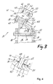
- Fig. 3
- die Verbindungsvorrichtung gem.
Fig. 2 im Schnitt; - Fig. 4
- das Detail IV der Verbindungsvorrichtung gem.
Fig. 3 ; und - Fig.5
- ein zweites Ausführungsbeispiel einer Verbindungseinrichtung in einer Seitenansicht.
- Die in der
Figur 1 dargestellte Ständerkonstruktion 11 für Solarpaneele 7 weist mehrere, in den Untergrund gerammte Stützprofile 12 sowie ein Raster 13 aus mehreren Quertragprofilen 14, welche von Stützprofil 12 zu Stützprofil 12 verlaufen, und aus mehreren Längstragprofilen 15 auf, die quer zu den Quertragprofilen 14 angeordnet sind. Zwischen den Stützprofilen 12 und den Quertragprofilen 14, ist jeweils eine Verbindungsvorrichtung 21 vorgesehen. - Die in den
Figuren 2 bis 4 im Detail dargestellte Verbindungsvorrichtung 21 weist ein Basiselement 22 und ein Aufnahmeelement 41 auf, das mittels einer Feststelleinrichtung 61 relativ zum Basiselement 22 an diesem festlegbar ist. - Das Basiselement 22 weist einen Befestigungsabschnitt 23 zur Anordnung an einem Stützprofil 12 der Ständerkonstruktion 11 auf, der von zwei, parallel zueinander verlaufenden Seitenwänden 24 und 25 sowie einen diese verbindenden Verbindungsabschnitt 26 gebildet ist. In den Seitenwänden 24 und 25 ist jeweils eine Durchführöffnung 27 für ein als Spannschraube mit Mutter ausgebildetes Verspannmittel 17 vorgesehen. Die Durchführöffnungen 27 liegen auf einer gemeinsamen Achse 28. Das Basiselement 22 wird mit dem Befestigungsabschnitt 23 voran in einen am Stützprofil 12 vorgesehenen Aufnahmeraum 16 eingesetzt und in der gewünschten Höhe relativ zum Stützprofil 12 mittels des Verspannmittels 17 an diesem festgelegt. Für eine Justierung der Position der Verbindungsvorrichtung 21 in Richtung der Längserstreckung des Stützprofils 12 sind zwei einander gegenüberliegende Langlöcher 18 in den einander gegenüberliegenden Wandungen des Stützprofils 12 entlang der Längserstreckung des Stützprofils 12 vorgesehen.
- Weiter weist das Basiselement 22 einen Auflageabschnitt 29 mit einer dem Aufnahmeelement 41 zugewandten Auflageseite 30 auf. Die von dem Auflageabschnitt 29 aufgespannte Ebene schliesst mit der von der Seitenwand 24 aufgespannten Ebene einen Winkel A im Bereich von 90° bis 140° ein. Dieser Winkel A wird vorteilhaft entsprechend der Neigung gewählt, welche das in dem Aufnahmeelement 41 aufgenommene Quertragprofil 14 aufweisen soll und welche nahezu der gewünschten Neigung der Solarpaneele 7 entspricht. Der Auflageabschnitt 29 des Basiselementes 22 weist einen den Befestigungsabschnitt 23 beziehungsweise dessen Seitenwand 25 überragenden Fixierabschnitt 31 auf. Im Fixierabschnitt 31 ist eine erste Durchführöffnung 32 und zwischen den Seitenwänden 24 und 25 des Befestigungsabschnitts 23 ist eine zweite Durchführöffnung 34 im Auflageabschnitt 29 vorgesehen. Die erste Durchführöffnung 32 ist als gekrümmtes Langloch ausgebildet, dessen Radius dem Abstand zur zweiten Durchführöffnung 34 entspricht und dessen konkave Seite 33 der zweiten Durchführöffnung 34 zugewandt ist. Die zweite Durchführöffnung 34 weist ein Innengewinde auf.
- Zwischen der ersten Durchführöffnung 32 und der zweiten Durchführöffnung 34 ist ein Absatz 35 an der Auflageseite 30 des Auflageabschnitts 29 vorgesehen, womit ein Anlagebereich 36 und ein Vertiefungsbereich 37 geschaffen wird, der gegenüber einer von dem Anlagebereich 36 aufgespannten Ebene zurückversetzt ist. Der Absatz 35 verläuft geneigt in einem Winkel von etwa 45° in Bezug auf eine von dem Anlagebereich 36 der Auflageseite 30 aufgespannten Ebene.
- Das U-förmige Aufnahmeelement 41 weist eine Aufnahme 42 für das Quertragprofil 14 der Ständerkonstruktion 11 auf, die dreiseitig begrenzt ist. Die Aufnahme 42 ist einerseits von zwei einander gegenüberliegenden Seitenwänden 43 und von einem die Seitenwände 43 verbindenden Anlageabschnitt 44 begrenzt. Der Anlageabschnitt 44 weist eine dem Basiselement 22 zugewandte Anlageseite 45 und an seiner gegenüberliegenden Seite einen parallel zu den Seitenwänden 43 verlaufenden Verstärkungssteg 46 auf. Im Bereich des Verstärkungsstegs 46 sind eine erste Durchführöffnung 47, die ein Innengewinde aufweist, und eine zu der ersten Durchführöffnung 47 beabstandete, zweite Durchführöffnung 48 vorgesehen.
- An jeder Seitenwand 43 des Aufnahmeelementes 41 ist eine Festlegeeinrichtung 51 zum Festlegen des in der Aufnahme 42 aufgenommenen Quertragprofils 14 vorgesehen. Die Festlegeeinrichtung 51 umfasst in jeder Seitenwand 43 eine Bohrung 52 und ein dazu beabstandetes, gekrümmt verlaufendes Langloch 53. Der Radius des Langlochs 53 entspricht dem Abstand der Bohrung 52 zum Langloch 53 und die konkave Seite des Langlochs 53 ist jeweils der Bohrung 52 zugewandt. Weiter umfasst die Festlegeeinrichtung 51 ein Hintergreifteil 54, das in eine Hintergreifnut 19 des Quertragprofils 14 eingreifen kann und das zwei jeweils mit einem Innengewinde versehene Bohrungen 55 und 56 aufweist. In die Bohrungen 55 und 56 greift jeweils eine Spannschraube 57 und 58 ein, welche durch die Bohrung 52 beziehungsweise durch das Langloch 53 in den Seitenwänden 43 hindurchgeführt sind. Das Hintergreifteil 54 kann um eine von der Spannschraube 58 gebildeten Schwenkachse 59 zur Anpassung der Neigung des in der Aufnahme 42 aufgenommenen Quertragprofils 14 verschwenkt werden.
- Die Feststelleinrichtung 61 zum Festlegen des Aufnahmeelementes 41 an dem Basiselement 22 weist neben den Durchführöffnungen 32 und 34 im Basiselement 22 und neben den Durchführöffnungen 47 und 48 im Aufnahmeelement 41 eine erste Spannschraube als Spannmittel 62 auf, das durch die erste Durchführöffnung 32 im Basiselement 22 hindurchgeführt ist und in das Innengewinde der ersten Durchführöffnung 47 im Aufnahmeelement 41 eingreift. Das Spannmittel 62 ist im Anlagebereich 36 des Auflageabschnitts 29 des Basiselementes 22 beziehungsweise als Teil der Feststelleinrichtung 61 im Bereich des Fixierabschnitts 31 des Auflageabschnitts 29 des Basiselementes 22 vorgesehen. Zudem umfasst die Feststelleinrichtung 61 eine zweite Spannschraube als Lagermittel 63, das durch die zweite Durchführöffnung 48 im Aufnahmeelement 41 hindurchgeführt ist und in das Innengewinde der zweiten Durchführöffnung 34 im Basiselement 22 eingreift. Das Lagermittel 62 ist im Vertiefungsbereich 37 des Auflageabschnitts 31 des Basiselementes 22 vorgesehen.
- Im verspannten Zustand der Verbindungsvorrichtung 21 (siehe
Fig. 3 ) liegt das Aufnahmeelement 41 im Auflagebereich 36 des Auflageabschnitts 31 flächig an. Aufgrund des rückversetzten Vertiefungsbereichs des Auflageabschnitts 31 ist ein Spalt S geschaffen (sieheFig. 4 ). Das Lagermittel 63 wird mit einem geringeren Drehmoment als das Spannmittel 62 angezogen, so dass im verspannten Zustand der Verbindungsvorrichtung 21 eine Zugkraft auf das Lagermittel 63 ausgeübt wird. Dem Anwender wird die Verbindungsvorrichtung 21 vorteilhaft in diesem Zustand zur Verfügung gestellt. - Zum Justieren des Aufnahmeelementes 41 relativ zum Basiselement 22 wird das Spannmittel 62 gelöst, wobei das Aufnahmeelement 41 über die von dem Absatz 35 gebildete Kippkante in Richtung der Seitenwand 24 des Befestigungsabschnitts 23 verkippt. In diesem Zustand ist das Aufnahmeelement 41 um eine von dem Lagermittel 63 gebildete Schwenkachse 64 verschwenkbar, ohne dass das Lagermittel 63 gelöst werden muss. Wird das Spannmittel 62 wieder verspannt, kippt das Aufnahmeelement 41 wieder zurück, bis dieses erneut auf dem Auflagebereich 36 des Auflageabschnitts 31 des Basiselementes 22 flächig anliegt. Gleichzeitig wird wieder das Lagermittel 63 auf Zug beansprucht, womit das Aufnahmeelement 41 in der gewünschten Ausrichtung relativ zum Basiselement 22 fixiert ist. Zum Justieren und Fixieren des Aufnahmeelementes 41 relativ zum Basiselement 22 muss somit nur das Spannmittel 62 gelöst beziehungsweise verspannt werden.
- Die in der
Figur 5 gezeigte Verbindungsvorrichtung 71 unterscheidet sich von der zuvor dargelegten Verbindungsvorrichtung 21 durch die Anordnung des Anlagebereichs und des Vertiefungsbereichs an der Anlageseite des Aufnahmeelementes sowie durch die andere Ausgestaltung der Festlegeeinrichtung 51 zum Festlegen des in der Aufnahme 42 aufgenommenen Quertragprofils 14. Ansonsten entsprechen die Elemente der Verbindungsvorrichtung 71 in Bezug auf die weiteren Merkmale im Wesentlichen der Verbindungsvorrichtung 21. - Die Auflageseite 80 des Auflageabschnitts 79 des Basiselementes 72 verläuft eben, entlang einer Ebene ohne einen in diesem vorgesehenen Absatz. Das Aufnahmeelement 91 mit der Aufnahme 92 für das Quertragprofil 14 weist an der Anlageseite 95 des Anlageabschnitts 94 einen Absatz 98 auf, der zwischen dem Spannmittel 112 und dem Lagermittel 113 der Feststelleinrichtung 111 einen Auflagebereich 96 und einen Vertiefungsbereich 97 der Anlageseite 95 ausbildet. Beim Lösen des Spannmittels 112 verkippt das Aufnahmeelement 91 zum Basiselement 72 hin und ist relativ zu diesem um die von dem Lagermittel 113 gebildeten Schwenkachse 114 verschwenkbar.
- Die an der Seitenwand 93 des Aufnahmeelementes 91 angeordnete Festlegeeinrichtung 101 weist ein Hintergreifteil 104 auf, das in die Hintergreifnut 19 des Quertragprofils 14 eingreift und über die Spannschrauben 107 und 108 zur Festlegung des Quertragprofils 14 in der Aufnahme 92 verspannbar ist. Bei der Verbindungsvorrichtung 71 ist das in der Seitenwand 93 vorgesehene, gekrümmte verlaufende Langloch 103 oberhalb des Spannmittels 112 und die in der Seitenwand 93 vorgesehene Bohrung 102 oberhalb des Lagermittels 113 vorgesehen. Das Hintergreifteil 104 ist um die von der Spannschraube 107 gebildete Schwenkachse 109 zur Anpassung der Neigung des in der Aufnahme 92 aufgenommenen Quertragprofils 14 verschwenkbar.
Claims (10)
- Verbindungsvorrichtung für eine Ständerkonstruktion (11) aus Stützprofilen (12) und aus Tragprofilen (14, 15), insbesondere zur Anordnung von Solarpaneelen (7), mit einem Basiselement (22; 72), mit einem Aufnahmeelement (41; 91) und mit einer Feststelleinrichtung (61; 111) mittels der das Aufnahmeelement (41; 91) relativ zum Basiselement (22; 72) an diesem festlegbar ist, wobei
das Basiselement (22; 72) einen Befestigungsabschnitt (23) zur Anordnung an einem Stützprofil (12) der Ständerkonstruktion (11) sowie einen Auflageabschnitt (29; 79) mit einer dem Aufnahmeelement (41; 91) zugewandten Auflageseite (30; 80) aufweist, und wobei
das Aufnahmeelement (41; 91) eine Aufnahme (42; 92) für ein Tragprofil (14) der Ständerkonstruktion (11) sowie einen Anlageabschnitt (44; 94) mit einer dem Basiselement (22; 72) zugewandten Anlageseite (45; 95) aufweist, dadurch gekennzeichnet, dass
die Feststelleinrichtung (61; 111) zumindest ein Spannmittel (62; 112) sowie zumindest ein Lagermittel (63; 113) aufweist, und dass zwischen dem Spannmittel (62; 112) und dem Lagermittel (63; 113) ein Anlagebereich (36; 96) und zumindest ein Vertiefungsbereich (37; 97) vorgesehen sind. - Verbindungsvorrichtung nach Anspruch 1, dadurch gekennzeichnet, dass das zumindest eine Spannmittel (62; 112) im Anlagebereich (36; 96) und das zumindest eine Lagermittel (63; 113) im zumindest einen Vertiefungsbereich (37; 97) vorgesehen sind.
- Verbindungsvorrichtung nach Anspruch 1 oder 2, dadurch gekennzeichnet, dass ein Absatz (35; 98) zwischen dem Anlagebereich (36; 96) und dem zumindest einen Vertiefungsbereich (37; 97) vorgesehen ist.
- Verbindungsvorrichtung nach Anspruch 3, dadurch gekennzeichnet, dass der Absatz (35) an der Auflageseite (30) des Auflageabschnitts (29) des Basiselementes (22) vorgesehen ist.
- Verbindungsvorrichtung nach einem der Ansprüche 1 bis 4, dadurch gekennzeichnet, dass der Auflageabschnitt (29; 79) des Basiselementes (22; 72) einen den Befestigungsabschnitt (23) an zumindest einer Seite des Befestigungsabschnitts (23) überragenden Fixierabschnitt (31) aufweist und zumindest ein Teil der Feststelleinrichtung (62; 112) im Bereich dieses Fixierabschnitts (31) vorgesehen ist.
- Verbindungsvorrichtung nach einem der Ansprüche 1 bis 5, dadurch gekennzeichnet, dass das Basiselement (22) eine erste Durchführöffnung (32) für das zumindest eine Spannmittel (62) und eine zweite Durchführöffnung (34) für das zumindest eine Lagermittel (63) im Auflageabschnitt (29) sowie das Aufnahmeelement (41) eine erste Durchführöffnung (47) für das zumindest eine Spannmittel (62) und eine zweite Durchführöffnung (48) für das zumindest eine Lagermittel (63) im Anlageabschnitt (44) aufweist, wobei zumindest eine dieser Durchführöffnungen (32) als Langloch ausgebildet ist.
- Verbindungsvorrichtung nach Anspruch 6, dadurch gekennzeichnet, dass die erste Durchführöffnung (32) für das zumindest eine Spannmittel (62) im Auflageabschnitt (29) des Basiselementes (22) als Langloch ausgebildet ist.
- Verbindungsvorrichtung nach Anspruch 6 oder 7, dadurch gekennzeichnet, dass eine der Durchführöffnungen (34, 47) einen Gewindeabschnitt für ein am zumindest einen Spannmittel (62) und/oder für ein am zumindest einen Lagermittel (63) angeordnetes Gewinde aufweist.
- Verbindungsvorrichtung nach einem der Ansprüche 6 bis 8, dadurch gekennzeichnet, dass die erste Durchführöffnung (47) für das zumindest eine mit einem Gewinde versehene Spannmittel (62) im Anlageabschnitt (44) des Aufnahmeelementes (41) einen Gewindeabschnitt und die zweite Durchführöffnung (34) für das zumindest eine mit einem Gewinde versehene Lagermittel (63) im Auflageabschnitt (29) des Basiselementes (22) einen Gewindeabschnitt aufweisen.
- Ständerkonstruktion, insbesondere zur Anordnung von Solarpaneelen (7), mit mehreren Stützprofilen (12) und mit mehreren Tragprofilen (14, 15), wobei zwischen zumindest einem der Stützprofile (12) und zumindest einem der Tragprofile (14) eine Verbindungsvorrichtung (21) nach einem der Ansprüche 1 bis 9 vorgesehen ist.
Applications Claiming Priority (1)
| Application Number | Priority Date | Filing Date | Title |
|---|---|---|---|
| DE102009045209A DE102009045209A1 (de) | 2009-09-30 | 2009-09-30 | Verbindungsvorrichtung für eine Ständerkonstruktion |
Publications (2)
| Publication Number | Publication Date |
|---|---|
| EP2312236A2 true EP2312236A2 (de) | 2011-04-20 |
| EP2312236A3 EP2312236A3 (de) | 2014-03-12 |
Family
ID=43339819
Family Applications (1)
| Application Number | Title | Priority Date | Filing Date |
|---|---|---|---|
| EP10174669.1A Withdrawn EP2312236A3 (de) | 2009-09-30 | 2010-08-31 | Verbindungsvorrichtung für eine Ständerkonstruktion |
Country Status (4)
| Country | Link |
|---|---|
| US (1) | US8407961B2 (de) |
| EP (1) | EP2312236A3 (de) |
| CA (1) | CA2716241A1 (de) |
| DE (1) | DE102009045209A1 (de) |
Cited By (2)
| Publication number | Priority date | Publication date | Assignee | Title |
|---|---|---|---|---|
| WO2013143517A3 (de) * | 2012-03-30 | 2013-12-19 | Haticon Gmbh | Freilandgestellsystem |
| WO2020049374A1 (de) * | 2018-09-03 | 2020-03-12 | S-Rack K.K. | Justierbeschlag und tragsystem für solarmodule |
Families Citing this family (10)
| Publication number | Priority date | Publication date | Assignee | Title |
|---|---|---|---|---|
| US8661747B2 (en) * | 2010-07-23 | 2014-03-04 | Kristian Eide | Solar panel racking system |
| DE102011104455B4 (de) | 2011-06-08 | 2013-01-03 | Schletter Gmbh | Baugruppe eines Ständers für PV-Module, Halteaufsatz und Verfahren zum Montieren der Baugruppe |
| DE102011104452A1 (de) | 2011-06-08 | 2012-12-13 | Schletter Gmbh | Ständer für PV-Module |
| WO2012167774A2 (de) | 2011-06-08 | 2012-12-13 | Schletter Gmbh | Ständer für pv-module |
| US20130098858A1 (en) * | 2011-09-27 | 2013-04-25 | Northern States Metals Company | Support system for solar panels with modified joists |
| CA2860607A1 (en) * | 2012-03-15 | 2013-09-19 | Magna International Inc. | Solar panel mounting structure |
| DE102012011969B4 (de) * | 2012-03-19 | 2016-11-03 | K2 Systems Gmbh | Solarmodulhalter |
| US9316417B2 (en) * | 2012-06-29 | 2016-04-19 | Sunpower Corporation | Framing system for mounting solar collecting devices |
| DE202012104634U1 (de) * | 2012-11-29 | 2014-03-03 | Habdank Pv-Montagesysteme Gmbh & Co. Kg | Montagesystem für Solarmodule |
| DE102017102827B3 (de) * | 2017-02-13 | 2018-06-21 | Mounting Systems Gmbh | Trägervorrichtung mit C-Profil-Modulträger für Solarmodule |
Citations (1)
| Publication number | Priority date | Publication date | Assignee | Title |
|---|---|---|---|---|
| DE202006014047U1 (de) | 2006-09-13 | 2006-12-07 | Leichtmetallbau Schletter Gmbh | Stellsystem für aufgeständerte Solaranlagen |
Family Cites Families (8)
| Publication number | Priority date | Publication date | Assignee | Title |
|---|---|---|---|---|
| US4966631A (en) * | 1989-03-13 | 1990-10-30 | Chronar Corp. | Support for photovoltaic arrays |
| DE19934073B4 (de) * | 1999-07-19 | 2005-08-25 | Regen Energiesysteme Gmbh | Vorrichtung zur Befestigung von Solarmodulen |
| US6414237B1 (en) * | 2000-07-14 | 2002-07-02 | Astropower, Inc. | Solar collectors, articles for mounting solar modules, and methods of mounting solar modules |
| US7017317B2 (en) * | 2002-10-04 | 2006-03-28 | Leonard Thomas Capozzo | Decorative ceiling panel and fastening system |
| US7531741B1 (en) * | 2003-03-07 | 2009-05-12 | Sacred Power Corporation | Tracking solar shelter |
| DE202008001010U1 (de) * | 2008-01-23 | 2008-05-08 | SGGT Straßenausstattungen GmbH | Tragkonstruktion für Solarmodule |
| US8046961B1 (en) * | 2008-05-27 | 2011-11-01 | Solarcraft, Inc. | Tactical solar power system |
| DE202010000293U1 (de) * | 2009-10-09 | 2010-05-20 | Galaxy-Energy Gmbh | Solardachanordnung |
-
2009
- 2009-09-30 DE DE102009045209A patent/DE102009045209A1/de not_active Withdrawn
-
2010
- 2010-08-31 EP EP10174669.1A patent/EP2312236A3/de not_active Withdrawn
- 2010-09-29 US US12/893,488 patent/US8407961B2/en not_active Expired - Fee Related
- 2010-09-30 CA CA2716241A patent/CA2716241A1/en not_active Abandoned
Patent Citations (1)
| Publication number | Priority date | Publication date | Assignee | Title |
|---|---|---|---|---|
| DE202006014047U1 (de) | 2006-09-13 | 2006-12-07 | Leichtmetallbau Schletter Gmbh | Stellsystem für aufgeständerte Solaranlagen |
Cited By (4)
| Publication number | Priority date | Publication date | Assignee | Title |
|---|---|---|---|---|
| WO2013143517A3 (de) * | 2012-03-30 | 2013-12-19 | Haticon Gmbh | Freilandgestellsystem |
| WO2020049374A1 (de) * | 2018-09-03 | 2020-03-12 | S-Rack K.K. | Justierbeschlag und tragsystem für solarmodule |
| TWI707104B (zh) * | 2018-09-03 | 2020-10-11 | 日商思銳可股份有限公司 | 太陽能板之調整配件及攜載系統 |
| JP2021536208A (ja) * | 2018-09-03 | 2021-12-23 | S−Rack株式会社 | ソーラーパネル用の調節金具および支持システム |
Also Published As
| Publication number | Publication date |
|---|---|
| CA2716241A1 (en) | 2011-03-30 |
| US20110072741A1 (en) | 2011-03-31 |
| EP2312236A3 (de) | 2014-03-12 |
| US8407961B2 (en) | 2013-04-02 |
| DE102009045209A1 (de) | 2011-03-31 |
Similar Documents
| Publication | Publication Date | Title |
|---|---|---|
| DE102009045209A1 (de) | Verbindungsvorrichtung für eine Ständerkonstruktion | |
| DE102013112645B3 (de) | Türband | |
| EP2604867B1 (de) | Klemme | |
| DE102018221183B3 (de) | Justierbeschlag und Tragsystem für Solarmodule | |
| WO2012116777A2 (de) | Befestigungselement für solarmodulrahmen | |
| EP2527762A1 (de) | Befestigungsvorrichtung | |
| EP1561956A1 (de) | Verbindungsvorrichtung | |
| DE102005018687B3 (de) | An einem Dacheindeckungselement angebrachte Halterung zur lösbaren Befestigung eines Gegenstandes, insbesondere eines Solarmoduls | |
| EP2256432A2 (de) | Ständer für rechteckige Solarmodule | |
| WO2007068009A1 (de) | Vorrichtung zur befestigung eines trägers für sensoren, schaltmittel u. dgl. an schienen | |
| EP0439716A1 (de) | Anker für die Befestigung von Fassadenplatten an einer Wand | |
| EP0064290A1 (de) | Vorrichtung zur Halterung von Verkleidungsplatten und dgl. an Bauwerksteilen | |
| DE102018127282A1 (de) | Baugruppe eines Bandes zur um eine Scharnierachse scharniergelenkigen Verbindung eines Flügels mit einem Rahmen sowie Band mit dieser Baugruppe | |
| WO2010000403A2 (de) | Stabilisator mit justiervorrichtung für bodenverankerungen | |
| DE102009022780A1 (de) | Ständer für rechteckige Solarmodule | |
| EP4411275B1 (de) | Dachhaken | |
| DE2735825C2 (de) | ||
| CH700182B1 (de) | Rohrhalterung. | |
| EP0931885A2 (de) | Entwässerungsrinne | |
| DE202005002790U1 (de) | Bausatz zur Verbindung von Trägerelementen | |
| EP3742003B1 (de) | Haltevorrichtung für ein flächenelement | |
| DE102015118360A1 (de) | Halterung für plattenelemente von brüstungen, geländern und dergleichen | |
| EP2669959A2 (de) | Tragkonstruktion für Solarpaneele | |
| DE19860743C1 (de) | Wandhalter für Verkleidungstafeln, insbesondere Fassadenelemente | |
| EP1477624A1 (de) | Stellfuss |
Legal Events
| Date | Code | Title | Description |
|---|---|---|---|
| PUAI | Public reference made under article 153(3) epc to a published international application that has entered the european phase |
Free format text: ORIGINAL CODE: 0009012 |
|
| AK | Designated contracting states |
Kind code of ref document: A2 Designated state(s): AL AT BE BG CH CY CZ DE DK EE ES FI FR GB GR HR HU IE IS IT LI LT LU LV MC MK MT NL NO PL PT RO SE SI SK SM TR |
|
| AX | Request for extension of the european patent |
Extension state: BA ME RS |
|
| PUAL | Search report despatched |
Free format text: ORIGINAL CODE: 0009013 |
|
| AK | Designated contracting states |
Kind code of ref document: A3 Designated state(s): AL AT BE BG CH CY CZ DE DK EE ES FI FR GB GR HR HU IE IS IT LI LT LU LV MC MK MT NL NO PL PT RO SE SI SK SM TR |
|
| AX | Request for extension of the european patent |
Extension state: BA ME RS |
|
| RIC1 | Information provided on ipc code assigned before grant |
Ipc: E04B 1/26 20060101ALI20140205BHEP Ipc: E04B 1/19 20060101ALI20140205BHEP Ipc: F24J 2/52 20060101AFI20140205BHEP Ipc: E04B 1/24 20060101ALI20140205BHEP |
|
| 17P | Request for examination filed |
Effective date: 20140912 |
|
| RBV | Designated contracting states (corrected) |
Designated state(s): AL AT BE BG CH CY CZ DE DK EE ES FI FR GB GR HR HU IE IS IT LI LT LU LV MC MK MT NL NO PL PT RO SE SI SK SM TR |
|
| GRAP | Despatch of communication of intention to grant a patent |
Free format text: ORIGINAL CODE: EPIDOSNIGR1 |
|
| INTG | Intention to grant announced |
Effective date: 20141209 |
|
| GRAS | Grant fee paid |
Free format text: ORIGINAL CODE: EPIDOSNIGR3 |
|
| STAA | Information on the status of an ep patent application or granted ep patent |
Free format text: STATUS: THE APPLICATION IS DEEMED TO BE WITHDRAWN |
|
| 18D | Application deemed to be withdrawn |
Effective date: 20150421 |