EP2312595A2 - Bobine - Google Patents
Bobine Download PDFInfo
- Publication number
- EP2312595A2 EP2312595A2 EP10179433A EP10179433A EP2312595A2 EP 2312595 A2 EP2312595 A2 EP 2312595A2 EP 10179433 A EP10179433 A EP 10179433A EP 10179433 A EP10179433 A EP 10179433A EP 2312595 A2 EP2312595 A2 EP 2312595A2
- Authority
- EP
- European Patent Office
- Prior art keywords
- winding
- wires
- coil
- end side
- wire
- Prior art date
- Legal status (The legal status is an assumption and is not a legal conclusion. Google has not performed a legal analysis and makes no representation as to the accuracy of the status listed.)
- Granted
Links
Images


Classifications
-
- H—ELECTRICITY
- H01—ELECTRIC ELEMENTS
- H01F—MAGNETS; INDUCTANCES; TRANSFORMERS; SELECTION OF MATERIALS FOR THEIR MAGNETIC PROPERTIES
- H01F27/00—Details of transformers or inductances, in general
- H01F27/28—Coils; Windings; Conductive connections
- H01F27/2823—Wires
-
- H—ELECTRICITY
- H01—ELECTRIC ELEMENTS
- H01F—MAGNETS; INDUCTANCES; TRANSFORMERS; SELECTION OF MATERIALS FOR THEIR MAGNETIC PROPERTIES
- H01F17/00—Fixed inductances of the signal type
- H01F17/02—Fixed inductances of the signal type without magnetic core
-
- H—ELECTRICITY
- H01—ELECTRIC ELEMENTS
- H01F—MAGNETS; INDUCTANCES; TRANSFORMERS; SELECTION OF MATERIALS FOR THEIR MAGNETIC PROPERTIES
- H01F41/00—Apparatus or processes specially adapted for manufacturing or assembling magnets, inductances or transformers; Apparatus or processes specially adapted for manufacturing materials characterised by their magnetic properties
- H01F41/02—Apparatus or processes specially adapted for manufacturing or assembling magnets, inductances or transformers; Apparatus or processes specially adapted for manufacturing materials characterised by their magnetic properties for manufacturing cores, coils, or magnets
- H01F41/04—Apparatus or processes specially adapted for manufacturing or assembling magnets, inductances or transformers; Apparatus or processes specially adapted for manufacturing materials characterised by their magnetic properties for manufacturing cores, coils, or magnets for manufacturing coils
- H01F41/06—Coil winding
- H01F41/064—Winding non-flat conductive wires, e.g. rods, cables or cords
- H01F41/069—Winding two or more wires, e.g. bifilar winding
- H01F41/07—Twisting
-
- H—ELECTRICITY
- H01—ELECTRIC ELEMENTS
- H01F—MAGNETS; INDUCTANCES; TRANSFORMERS; SELECTION OF MATERIALS FOR THEIR MAGNETIC PROPERTIES
- H01F41/00—Apparatus or processes specially adapted for manufacturing or assembling magnets, inductances or transformers; Apparatus or processes specially adapted for manufacturing materials characterised by their magnetic properties
- H01F41/02—Apparatus or processes specially adapted for manufacturing or assembling magnets, inductances or transformers; Apparatus or processes specially adapted for manufacturing materials characterised by their magnetic properties for manufacturing cores, coils, or magnets
- H01F41/04—Apparatus or processes specially adapted for manufacturing or assembling magnets, inductances or transformers; Apparatus or processes specially adapted for manufacturing materials characterised by their magnetic properties for manufacturing cores, coils, or magnets for manufacturing coils
- H01F41/06—Coil winding
- H01F41/082—Devices for guiding or positioning the winding material on the former
- H01F41/084—Devices for guiding or positioning the winding material on the former for forming pancake coils
-
- H—ELECTRICITY
- H01—ELECTRIC ELEMENTS
- H01F—MAGNETS; INDUCTANCES; TRANSFORMERS; SELECTION OF MATERIALS FOR THEIR MAGNETIC PROPERTIES
- H01F41/00—Apparatus or processes specially adapted for manufacturing or assembling magnets, inductances or transformers; Apparatus or processes specially adapted for manufacturing materials characterised by their magnetic properties
- H01F41/02—Apparatus or processes specially adapted for manufacturing or assembling magnets, inductances or transformers; Apparatus or processes specially adapted for manufacturing materials characterised by their magnetic properties for manufacturing cores, coils, or magnets
- H01F41/04—Apparatus or processes specially adapted for manufacturing or assembling magnets, inductances or transformers; Apparatus or processes specially adapted for manufacturing materials characterised by their magnetic properties for manufacturing cores, coils, or magnets for manufacturing coils
- H01F41/06—Coil winding
- H01F41/082—Devices for guiding or positioning the winding material on the former
- H01F41/086—Devices for guiding or positioning the winding material on the former in a special configuration on the former, e.g. orthocyclic coils or open mesh coils
-
- H—ELECTRICITY
- H01—ELECTRIC ELEMENTS
- H01F—MAGNETS; INDUCTANCES; TRANSFORMERS; SELECTION OF MATERIALS FOR THEIR MAGNETIC PROPERTIES
- H01F27/00—Details of transformers or inductances, in general
- H01F27/28—Coils; Windings; Conductive connections
- H01F27/2871—Pancake coils
-
- H—ELECTRICITY
- H01—ELECTRIC ELEMENTS
- H01F—MAGNETS; INDUCTANCES; TRANSFORMERS; SELECTION OF MATERIALS FOR THEIR MAGNETIC PROPERTIES
- H01F37/00—Fixed inductances not covered by group H01F17/00
- H01F37/005—Fixed inductances not covered by group H01F17/00 without magnetic core
-
- H—ELECTRICITY
- H01—ELECTRIC ELEMENTS
- H01F—MAGNETS; INDUCTANCES; TRANSFORMERS; SELECTION OF MATERIALS FOR THEIR MAGNETIC PROPERTIES
- H01F38/00—Adaptations of transformers or inductances for specific applications or functions
- H01F38/14—Inductive couplings
Definitions
- the present invention relates to an advantageous coil as a thin-type coil for use in an electric device, and more particularly to a coil in which either of a first end of wire and a second end of wire is wound from an inner circumferential side towards an outer circumferential side, whereas the other end of wire is drawn forth from the inner circumferential side to the outer circumferential side.
- An ⁇ winding method is generally known as a method for winding a coil by which a first end of wire and a second end of wire are both wound around from the inner circumferential side towards the outer circumferential side.
- a winding shaft is set close to the center at both ends of the wires and the first end of the wire and the second end of the wire are wound in mutually opposite directions, whereby a coil can be formed in which both the first end of the wire and the second end of the wire are drawn forth to the outside.
- a method is also known by which a winding start end side of a coil is fixed, the winding completion end side is wound from the inner circumferential side towards the outer circumferential side and the winding start end is drawn forth from the inner circumferential side towards the outer circumferential side.
- the winding start end is dragged over the flat surface of the wound coil, and the draw-forth line portion of the winding start end side becomes larger in size (thickness) in the height direction by the diameter of the winding wire at the winding start end.
- a known measure for resolving this problem is to provide a concavity on the flat surface of the wound coil along the draw-forth line of the winding start end on the flat surface of the wound coil (see Japanese Patent Application Laid-open No. 2006-049750 ).
- the problem related to the coil described in Japanese Patent Application Laid-open No. 2002-170729 is that because the first end of the wire and the second end of the wire are wound in the mutually opposite directions and the winding wires are piled up in two layers at the crossing portions thereof, a portion with a height twice the diameter of the wires appears along the crossing portions. Further, when the coil is an air-core coil, problems are related to the coil strength because of the structure in which the winding wires are piled up in two layers.
- the present invention has been created to resolve the above-described problems and it is an object thereof to provide a coil in which one of a first end of wire and a second end of wire is wound from an inner circumferential side towards an outer circumferential side, and the other one of the first end of the wire and the second end of the wire is drawn forth from the inner circumferential side to the outer circumferential side, wherein a significant increase in a winding height at crossing portions of the first end of the wire and the second end of the wire compared to a winding height in other portions is prevented and the coil can be easily manufactured.
- the coil in accordance with the present invention has the following features that make it possible to attain the above-described object.
- the coil in accordance with the present invention comprises first ends and second ends of winding wire which is formed by a plurality of wires, where one of the first ends and the second ends of the winding wire are wound from an inner circumferential side towards an outer circumferential side and the other of the first ends and the second ends of the winding wire is drawn from the inner circumferential side towards the outer circumferential side, wherein the plurality of wires are wound together in a state of being piled up in a vertical direction, and the plurality of wires are superimposed and caused to cross each other in a state in which the plurality of wires are laid down transversely at crossing portions of the first ends of the wires and the second ends of the wires.
- the first ends of the wires are wound from the inner circumferential side towards the outer circumferential side, the second ends of the wires are drawn forth to the outer circumferential side so as to form a curve, and the crossing portions are arranged so as to be displaced in the circumferential direction towards the outer circumference. It is also preferred that in this case the second ends of the wires are drawn by winding of an integer number of turns from the inner circumferential side towards the outer circumferential side to form a curve on a coil flat surface and then drawn forth to the outer circumferential side.
- the plurality of wires may be constituted by self-fusing wires.
- the coil in accordance with the present invention may be an air-core coil. Still further, an outer contour shape and a shape of each corner of the air-core portion may be either of rounded rectangular shape or elliptical shape. In addition, the coil in accordance with the present invention is constituted for using in contactless power transmission.
- a mode of transition from "the state in which the plurality of wires are piled up in a vertical direction" to "the state in which the plurality of wires are laid down transversely” is a mode in which an arrangement state of the plurality of wires is changed to an arrangement state in which the plurality of wires are entirely twisted through 90 degrees, without changing the relative positional relationship of the plurality of wires (referred to hereinbelow as “twisting mode") or a mode in which the relative positional relationship of the plurality of wires is allowed to change and the arrangement state of the plurality of wires is crushed in the vertical direction to obtain a flat configuration in the transverse direction (referred to hereinbelow as "crushing mode").
- the twisting mode is effective when the plurality of wires have already been integrally fixed at the winding stage, and the crushing mode is effective when the plurality of wires can be separated from one another at the winding stage.
- the plurality of wires are superimposed and caused to cross each other in a state in which the plurality of wires are laid down transversely. Therefore, the height at the crossing portions can be greatly reduced with respect to that in the related art and made equal to that in other regions.
- the coil can be easily wound, without using a winding apparatus of larger size, as in the case in which the ⁇ winding method is used.
- FIGS. 1 to 5 and FIG. 12 An embodiment of the coil in accordance with the present invention will be described below with reference to FIGS. 1 to 5 and FIG. 12 .
- FIG. 1 shows a coil 10 of the present embodiment, and a basic shape serving as a prototype thereof is shown in FIG. 12 .
- FIG. 1 illustrates a case in which only four below-described crossing portions are provided for purpose of convenience of explanation.
- the word "wire” is used in an explanation of the present invention.
- the "wire” means one line-shaped material provided with an insulated film on a surface of conductor which has conductivity such as copper, silver, etc.
- a coil 10D shown in FIG. 12 is a flat air-core monolayer spirally wound coil (for example, disclosed in Japanese Patent Application Laid-open No. 2007-324532 ).
- this coil two winding wires having a diameter about half that of the winding wire that has been usually used are piled up vertically.
- the two winding wires are wound together from the inner circumferential side towards the outer circumferential side, whereas at the winding start end side remaining at the inner circumferential side, the winding wire is drawn forth from the inner circumferential side towards the outer circumferential side along the flat surface of the coil 10D.
- the configuration of the coil of the present embodiment is such that at the crossing portions of the winding wire 1 at the winding completion end side and the winding wire 1 at the winding start end side, the winding wires 1 (more specifically, two wires constituting the winding wire 1) are superimposed and caused to cross each other in a state in which the winding wires are laid down transversely.
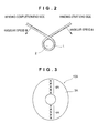
- FIG. 1A when the winding wire 1 at the winding start end side is drawn forth from the inner peripheral side towards the outer peripheral side, the winding wire 1 is drawn forth, while being wound one turn clockwise. In each position in which the winding wire 1 at the winding start end side is wound through 90 degrees (positions 1, 2, 3, and 4 in FIG. 1A (in the figure, these numerals are enclosed in circles)), this winding wire 1 crosses the winding wire 1 of the next turn on the winding completion end side.
- the two wires that have been piled up vertically in the winding wire 1 at the winding completion end side are laid down transversely (twisting mode), and the winding wire 1 at the winding start end side that has been drawn forth from the inner peripheral side towards the outer peripheral side in a state in which the two wires were originally laid down transversely is superimposed on the aforementioned winding wire 1 and caused to cross it.
- the winding wire 1 of the first turn at the winding completion end side and the winding wire 1 at the winding start end side cross each other.
- the winding wire 1 of the second turn at the winding completion end side and the winding wire 1 at the winding start end side cross each other.
- the winding wire 1 of the third turn at the winding completion end side and the winding wire 1 at the winding start end side cross each other.
- the winding wire 1 of the fourth turn at the winding completion end side and the winding wire 1 at the winding start end side cross each other.
- the crossing portions 4A thereof will be arranged along a straight line in the radial direction, as shown in FIG. 3 .
- a flat surface 3A of a coil 10A will have an elliptical shape.
- crossing portions 4A are prevented from being arranged in a single row in the radial direction.
- crossing portions 4B are arranged so as to form a spiral from the inner circumferential side towards the outer circumferential side as shown in FIG. 4 , the linear arrangement in the radial direction is prevented, and a flat surface 3B of a coil 10B has a shape close to a real circle.
- a method for winding of the winding wire 1, as the crossing portions 4B is spirally formed on the flat surface 3B of the coil 10B includes, for example, as shown in FIG. 2 , winding the winding wire 1 at the winding start end side and the winding wire 1 at the winding completion end side around the winding shaft 2 so that the angular speed A of the winding wire 1 of the former and the angular speed B of the winding wire 1 of the latter differ from each other, and gradually displacing the crossing position in the circumferential direction towards the outer circumferential side.
- the difference between the angular speeds A and B will create a difference between the number of turns of the winding wire 1 at the winding start end side and the number of turns of the winding wire 1 at the winding completion end side and therefore the winding angles of the two winding wires 1 from one crossing portion to the next crossing portion will differ from each other.
- the flat surface 3A of the coil 10A can be prevented from becoming an elliptical shape, as shown in FIG. 3 .
- the coil flat surface is formed closer to a real circular shape by setting the number of turns at the winding start end side to an integer number (the start point of winding of the winding wire 1 at the winding start end side is in the position of the crossing portion 4B with the winding wire 1 at the winding completion end side that is on the innermost peripheral side).
- the crossing portions 4 are assumed to appear for every 90 degrees, for purpose of convenience of explanation, but actually by setting the winding to a larger difference between the number of turns of the winding wire 1 at the winding start end side and the number of turns of the winding wire 1 at the winding completion end side, it is possible to create the crossing portions with a smaller angular spacing and carry across the winding wire 1 at the winding start end side so as to follow the crossing portions 4, thereby making it possible to adjust the height of the winding wire 1 at the winding start end side over almost the entire draw-forth region to that in the other regions.
- the crossing portions 4B of the winding wire 1 at the winding completion end side and the winding wire 1 at the winding start end side will be present for each single turn of the winding wire 1 at the winding completion end side and a total of 15 crossing portions will be present.
- the coil when the coil 10 is manufactured, the coil can be formed, as described hereinabove, by winding clockwise either of the winding wire 1 at the winding completion end side and the winding wire 1 at the winding start end side and winding counterclockwise the other of the two, the two winding wires being wound at mutually different angular speeds.
- a winding method may be used by which the winding wire 1 at the winding completion end side is wound through 360° - 24°, the winding operation is then temporarily stopped, the winding wire 1 at the winding start end side is dragged to the crossing portion 4, the winding wire 1 at the winding completion end side is again wound through 360° - 24°, the winding operation is then temporarily stopped, and the winding wire 1 at the winding start end side is dragged to the next crossing portion 4.
- the entire processing (crossing portion creation processing) by which a winding wire arrangement in which the two wires are piled up vertically is temporarily changed to that in which the wires are laid down transversely may be performed at the very beginning when the winding wire 1 at the winding completion end side is wound with respect to the locations where the winding start is disposed in the completed product, and then the winding wire 1 at the winding start end may be laid down along the concave positions (crossing portions) that are laid down transversely, when the coil flat surface 3 is viewed from above.
- the number of turns at the winding completion end side is 15 and the number of turns at the winding start end side is 1, but these numbers are not limiting, and any number N of turns at the winding completion end side can be selected.
- the number of turns at the winding start end side is 1, a crossing portion may be present for each 360° - 360°/N range.
- winding wires are round, but such a shape is not limiting and rectangular wires or angular wires may be also wound.
- a cross section in the form of a rectangle with a 2:1 ratio is preferred.
- the wiring wire 1 at the winding completion end side is wound with a longer side in the vertical direction
- the winding wire 1 is toppled in the crossing portion so that the longer side is oriented in the horizontal direction
- the winding wire 1 at the winding start end side that has been arranged to have the longer side in the horizontal direction is laid down on top thereof.
- the height in the crossing portion can be adjusted to that in other portions, and similarly to the above-described embodiment, the problem of the height as a total being increased by the height of the drawn-forth wire can be resolved (see FIG. 1C ; the number in the wiring wire in the figure represents the number of winding turns; the reference number 3' represents a flat surface of the coil and 10' represents the coil).
- FIG. 5 shows a schematic cross-section of a coil 10C in a case in which five wires are wound together.
- the arrangement of five wires in the crossing portion 4C is crushed in the vertical direction and flattened in the transverse direction, thereby spreading the lower layer into five wires (crushing mode).
- the wires of the winding wire 1 at the wiring start end side are laid down on top of the lower layer in the vacant upper layer as a row consisting of five wires. The total height in the crossing portion 4C is thus adjusted to that in other regions.
- FIG. 6 shows schematically a coil 10E in which two wires are wound together in the same manner as in the above-descried coil 10 ( FIG. 6A is a plan view, FIG. 6B is a cross-sectional view taken along the X-X line in FIG. 6A ).
- FIG. 6B the numerical values introduced in the cross section represent the number of winding turns in the winding wires (the same is in FIGS. 7 to 9 below).
- a winding wire is constituted by two wires.
- a winding wire 11E at the wiring completion end side (only the innermost circumferential portion is numbered in FIG. 6A ) is tightly wound (about 7 turns) counterclockwise from the inner circumference to the outer circumference.
- a winding wire 12E at the winding start end side (hatched winding wire) is drawn forth from the inner circumference to the outer circumference, while crossing the winding wire 11E at the wiring completion end side and being wound (about 1 turn) clockwise so as to form a smooth spiral curve.
- the thickness in the vertical direction (direction of the winding shaft axis C 10E ) in the crossing portion of the winding wire 11E at the wiring completion end side and the winding wire 12E at the winding start end side is equal to that in other portions.
- the winding wire 12E at the winding start end side (hatched winding wire) is wound in a state in which two wires are arranged side by side in the transverse direction (radial direction), whereas the winding wire 11 E at the wiring completion end side (winding wire in which a digit is inserted into a circle) is wound in a state in which the two wires are piled up vertically in portions where the winding wire 12E at the winding start end side is not crossed and wound in a state in which the two wires are laid down transversely in portions where the winding wire 12E at the winding start end side is crossed (when the arrangement state of the wires of the winding wire 11E at the wiring completion end side is changed, since the number of the wires is as small as two, both the crushing mode and the twisting mode can be realized).
- the thickness in the vertical direction in the crossing portions of the winding wire 11E at the wiring completion end side and the winding wire 12E at the winding start end is changed, since the number of the wires is as small
- FIG. 7 shows a cross section of a coil 10F constituted by winding wires composed of eight wires.
- a winding wire 12F at the winding start end side is normally wound in a state in which the eight wires are arranged in four rows in the transverse direction (radial direction) and arranged in two rows in the vertical direction (direction of the winding shaft axis C 10F ), whereas a winding wire 11F at the winding completion end side is wound in a state in which the eight wires are piled up vertically and arranged in two rows in the transverse direction and in four rows in the vertical direction in portions where the winding wire 12F at the winding start end side is not crossed and wound in a state in which the eight wires are laid down transversely and arranged in four rows in the transverse direction and in two rows in the vertical direction in portions where the winding wire 12F at the winding start end side is crossed (when the arrangement state of the wires of the winding wire 11F at the winding completion end side is changed,
- FIG. 8 shows a cross section of a coil 10G constituted by winding wires composed of six wires.
- a winding wire 12G at the winding start end side is normally wound in a state in which the six wires are arranged in six rows in the transverse direction (radial direction) and arranged in one row in the vertical direction (direction of the winding shaft axis C 10G ), whereas a winding wire 11G at the winding completion end side is wound in a state in which the six wires are piled up vertically and arranged in two rows in the transverse direction and in three rows in the vertical direction in portions where the winding wire 12G at the winding start end side is not crossed and wound in a state in which the six wires are laid down transversely and arranged in three rows in the transverse direction and in two rows in the vertical direction in portions where the winding wire 12G at the winding start end side is crossed (when the arrangement state of the wires of the winding wire 11G at the winding completion end side is changed,
- FIG. 9 shows a cross section of a coil 10H constituted by winding wires composed of eight wires.
- a winding wire 12H at the winding start end side is normally wound in a state in which the eight wires are arranged in eight rows in the transverse direction (radial direction) and arranged in one row in the vertical direction (direction of the winding shaft axis C 10H )
- a winding wire 11H at the winding completion end side is wound in a state in which the eight wires are piled up vertically and arranged in two rows in the transverse direction and in four rows in the vertical direction in portions where the winding wire 12H at the winding start end side is not crossed and wound in a state in which the arrangement state of the eight wires is crushed in the vertical direction and flattened in the transverse direction (an arrangement state with three rows in the vertical direction and three rows or two rows in the transverse direction), so that the eight wires of the winding wire 12H at the winding start end side fill successively the spaces
- An air-core coil in a wound state obtained with the crushing mode is formed by the following winding method.
- a winding wire at the winding start end side and a winding wire at the winding completion end side in which each wire is constituted by the so-called self-fusing wire for example, a copper wire coated with polyurethane that is further coated on the outer side with a thermoplastic fusible varnish or the like
- self-fusing wire for example, a copper wire coated with polyurethane that is further coated on the outer side with a thermoplastic fusible varnish or the like
- the winding is wound by setting mutually different angular speed A of the winding wire at the winding start end side and angular speed B of the winding wire at the winding completion end side, while controlling the thickness in the winding shaft direction (direction perpendicular to the paper sheet) to the thickness of a predetermined number of wires (in the case of the coil 10E, the thickness of two wires; in the case of the coils 10F and 10H, the thickness of four wires, and in the case of the coil 10G, the thickness of three wires) with a winding frame (not shown in the figure) of the winding apparatus.
- a predetermined number of wires in the case of the coil 10E, the thickness of two wires; in the case of the coils 10F and 10H, the thickness of four wires, and in the case of the coil 10G, the thickness of three wires
- the wires of the winding wire at the winding completion end side are wound in an arrangement state in which they extend in the vertical direction through the entire thickness of the winding frame that is not shown in the figure (state in which the wires are piled up vertically) in portions in which the winding wire at the winding start end side is not crossed and wound in an arrangement state in which they are crushed in the vertical direction and flattened in the transverse direction (state in which they are laid down transversely) since the thickness is controlled by the winding frame (not shown in the figure) correspondingly to the thickness of the winding wire and the winding start end side (thickness of the number of wires arranged in the vertical direction) in portions in which the winding wire at the winding start end side is crossed.
- An air-core coil in a wound state produced in a crushing mode is then formed by conducting a fusion treatment after the winding is completed and removing from the winding shaft 2.
- FIGS. 5 , 7-9 as a preferred mode, it is explained a state in which wires at a winding start end side are piled up vertically in one or two rows and arranged longer in a transverse direction is retained, whereas a winding wire is drawn forth from an inner circumferential side to an outer circumferential side. It is also included to the embodiments of the present invention that a mode in which an arrangement that wires at a winding start end side change in number of rows from one to two or three as well as from three to two or one to the contrary.
- the coil of the above-described air-core type can be advantageously used for contactless power transmission (contact-free power transmission) in electric devices for which the decrease in thickness is essential, for example, cellular phones and portable information terminal devices, but the coil in accordance with the present invention is not limited to the air-core coil and can be also similarly applied to coils wound on a bobbin or core.
- the outer contour shape of the coil and the shape of each corner of the air-core portion are both circular, but they can also have a rounded rectangular shape or elliptical shape.
- both the outer contour and each corner of the air-core have a rounded rectangular shape
- both the outer contour and the air-core have an elliptical shape.
- winding wire at the winding completion end side two wires are piled up vertically and wound together from the inner circumferential side towards the outer circumferential side.
- the winding wire at the winding start end side that has remained on the inner circumferential side is drawn forth from the inner circumferential side to the outer circumferential side so as to form a curve along the flat surface of the coil.
- the two wires of each winding wire are superimposed and caused to cross each other in a state in which the wires are laid down transversely.
Landscapes
- Engineering & Computer Science (AREA)
- Power Engineering (AREA)
- Manufacturing & Machinery (AREA)
- Microelectronics & Electronic Packaging (AREA)
- Coils Of Transformers For General Uses (AREA)
- Windings For Motors And Generators (AREA)
- Coil Winding Methods And Apparatuses (AREA)
- Manufacturing Cores, Coils, And Magnets (AREA)
Applications Claiming Priority (2)
| Application Number | Priority Date | Filing Date | Title |
|---|---|---|---|
| JP2009239738 | 2009-10-16 | ||
| JP2010182794A JP5534442B2 (ja) | 2009-10-16 | 2010-08-18 | コイル |
Publications (3)
| Publication Number | Publication Date |
|---|---|
| EP2312595A2 true EP2312595A2 (fr) | 2011-04-20 |
| EP2312595A3 EP2312595A3 (fr) | 2013-04-24 |
| EP2312595B1 EP2312595B1 (fr) | 2014-08-13 |
Family
ID=43466579
Family Applications (1)
| Application Number | Title | Priority Date | Filing Date |
|---|---|---|---|
| EP10179433.7A Active EP2312595B1 (fr) | 2009-10-16 | 2010-09-24 | Bobine |
Country Status (4)
| Country | Link |
|---|---|
| US (1) | US8373532B2 (fr) |
| EP (1) | EP2312595B1 (fr) |
| JP (1) | JP5534442B2 (fr) |
| CN (1) | CN102044330B (fr) |
Cited By (3)
| Publication number | Priority date | Publication date | Assignee | Title |
|---|---|---|---|---|
| EP2413335A3 (fr) * | 2010-07-30 | 2017-07-26 | Sumida Corporation | Bobine |
| CN108369854A (zh) * | 2015-12-18 | 2018-08-03 | 西门子股份公司 | 绕组装置 |
| WO2018210842A1 (fr) * | 2017-05-15 | 2018-11-22 | Magcomp Ab | Bobine |
Families Citing this family (7)
| Publication number | Priority date | Publication date | Assignee | Title |
|---|---|---|---|---|
| JP2012230972A (ja) | 2011-04-25 | 2012-11-22 | Sumida Corporation | コイル部品、圧粉インダクタおよびコイル部品の巻回方法 |
| JP5391298B2 (ja) * | 2012-03-15 | 2014-01-15 | 昭和電線デバイステクノロジー株式会社 | リッツ線コイルおよび加熱装置 |
| EP2709118A1 (fr) * | 2012-09-14 | 2014-03-19 | Magnetic Components Sweden AB | Inducteur optimal |
| WO2016036420A1 (fr) * | 2014-09-05 | 2016-03-10 | PICHKUR, Dmytro | Transformateur |
| CN107516587B (zh) * | 2017-09-20 | 2020-06-09 | 中国科学院微电子研究所 | 一种电感以及制造电感的方法 |
| WO2019107236A1 (fr) * | 2017-11-28 | 2019-06-06 | 株式会社村田製作所 | Inductance et transformateur |
| CN116344172B (zh) * | 2023-03-17 | 2026-03-13 | 潍坊路加精工有限公司 | 电感线圈和电子设备 |
Citations (3)
| Publication number | Priority date | Publication date | Assignee | Title |
|---|---|---|---|---|
| JP2002170729A (ja) | 2000-11-30 | 2002-06-14 | Taiyo Yuden Co Ltd | コイルの製造方法及びコイル部品とその製造方法 |
| JP2006049750A (ja) | 2004-08-09 | 2006-02-16 | Okayama Giken:Kk | 導出壕を付与した空芯コイルとその製造方法 |
| JP2007324532A (ja) | 2006-06-05 | 2007-12-13 | Meleagros Corp | 電力伝送方法、電力伝送装置のコイルの選別方法および使用方法 |
Family Cites Families (20)
| Publication number | Priority date | Publication date | Assignee | Title |
|---|---|---|---|---|
| US512340A (en) * | 1893-07-07 | 1894-01-09 | Nikola Tesla | Coil for electro-magnets |
| US3676814A (en) * | 1970-02-06 | 1972-07-11 | Westinghouse Electric Corp | High temperature adhesive overcoat for magnet wire |
| CH625905A5 (en) * | 1977-07-05 | 1981-10-15 | Proizv Ob Uralelektrotyazhmash | Method for winding a transformer winding, and the transformer winding produced in accordance with this method |
| WO1987005147A1 (fr) * | 1986-02-14 | 1987-08-27 | Cornelius Lungu | Composant electrique presentant des proprietes inductives et capacitives |
| US4794361A (en) * | 1988-03-10 | 1988-12-27 | General Motors Corporation | Coil winding method for maximum utilization of winding envelope |
| JPH06301914A (ja) * | 1993-04-14 | 1994-10-28 | Canon Inc | 磁気ヘッド用コイルの巻回方法および磁気ヘッド |
| JP2000333433A (ja) * | 1999-05-20 | 2000-11-30 | Mosutetsuku:Kk | リニアモーター用コイル装置 |
| JP2002025833A (ja) * | 2000-07-05 | 2002-01-25 | Tokin Corp | 電磁コイル |
| JP4267951B2 (ja) * | 2003-03-28 | 2009-05-27 | 古河電気工業株式会社 | コイル |
| JP2004336984A (ja) * | 2003-04-18 | 2004-11-25 | Denso Corp | コイル、その製造方法およびその製造装置、ティース、コアならびに回転電機 |
| JP4192727B2 (ja) * | 2003-08-29 | 2008-12-10 | トヨタ自動車株式会社 | コイル巻線機 |
| JP4513805B2 (ja) * | 2004-03-09 | 2010-07-28 | パナソニック株式会社 | トランス |
| US8325001B2 (en) * | 2005-08-04 | 2012-12-04 | The Regents Of The University Of California | Interleaved three-dimensional on-chip differential inductors and transformers |
| EP1933340B1 (fr) * | 2005-09-08 | 2012-08-01 | Sumida Corporation | Dispositif à enroulement, dispositif à enroulement composite et dispositif transformateur |
| CN101325120A (zh) * | 2007-06-15 | 2008-12-17 | 台达电子工业股份有限公司 | 变压器及其线圈绕线方法 |
| EP2201583B1 (fr) * | 2007-09-12 | 2017-01-11 | Texas Instruments (Cork) Limited | Ensemble transformateur |
| JP2009158598A (ja) * | 2007-12-25 | 2009-07-16 | Panasonic Electric Works Co Ltd | 平面コイル及びこれを用いた非接触電力伝送機器 |
| JP4752879B2 (ja) * | 2008-07-04 | 2011-08-17 | パナソニック電工株式会社 | 平面コイル |
| US7830237B1 (en) * | 2009-08-19 | 2010-11-09 | Intelextron Inc. | Transformer |
| JP5532422B2 (ja) * | 2010-07-30 | 2014-06-25 | スミダコーポレーション株式会社 | コイル |
-
2010
- 2010-08-18 JP JP2010182794A patent/JP5534442B2/ja active Active
- 2010-09-15 US US12/882,480 patent/US8373532B2/en active Active
- 2010-09-17 CN CN2010102878845A patent/CN102044330B/zh active Active
- 2010-09-24 EP EP10179433.7A patent/EP2312595B1/fr active Active
Patent Citations (3)
| Publication number | Priority date | Publication date | Assignee | Title |
|---|---|---|---|---|
| JP2002170729A (ja) | 2000-11-30 | 2002-06-14 | Taiyo Yuden Co Ltd | コイルの製造方法及びコイル部品とその製造方法 |
| JP2006049750A (ja) | 2004-08-09 | 2006-02-16 | Okayama Giken:Kk | 導出壕を付与した空芯コイルとその製造方法 |
| JP2007324532A (ja) | 2006-06-05 | 2007-12-13 | Meleagros Corp | 電力伝送方法、電力伝送装置のコイルの選別方法および使用方法 |
Cited By (6)
| Publication number | Priority date | Publication date | Assignee | Title |
|---|---|---|---|---|
| EP2413335A3 (fr) * | 2010-07-30 | 2017-07-26 | Sumida Corporation | Bobine |
| CN108369854A (zh) * | 2015-12-18 | 2018-08-03 | 西门子股份公司 | 绕组装置 |
| CN108369854B (zh) * | 2015-12-18 | 2021-03-16 | 西门子股份公司 | 绕组装置 |
| WO2018210842A1 (fr) * | 2017-05-15 | 2018-11-22 | Magcomp Ab | Bobine |
| CN111226295A (zh) * | 2017-05-15 | 2020-06-02 | 科姆赛斯公司 | 线圈 |
| US12014862B2 (en) | 2017-05-15 | 2024-06-18 | Comsys Ab | Coil |
Also Published As
| Publication number | Publication date |
|---|---|
| US20110090035A1 (en) | 2011-04-21 |
| EP2312595A3 (fr) | 2013-04-24 |
| CN102044330B (zh) | 2013-05-01 |
| JP5534442B2 (ja) | 2014-07-02 |
| US8373532B2 (en) | 2013-02-12 |
| CN102044330A (zh) | 2011-05-04 |
| JP2011103439A (ja) | 2011-05-26 |
| EP2312595B1 (fr) | 2014-08-13 |
Similar Documents
| Publication | Publication Date | Title |
|---|---|---|
| EP2312595B1 (fr) | Bobine | |
| CN102347127B (zh) | 线圈 | |
| US8667666B2 (en) | Method for producing stator or rotor with interlaced wire groups forming an intertwined wave winding | |
| US9570966B2 (en) | Method for manufacturing a coil | |
| KR101282147B1 (ko) | 초전도체들을 이용한 안장형 코일 와인딩, 및 그 제조 방법 | |
| US8450900B2 (en) | Method for the mechanical winding of a coil | |
| US10574111B2 (en) | Rotating electric machine with lane-changed coils | |
| US20150228399A1 (en) | Coil device | |
| JP2012124396A (ja) | トロイダルコイル | |
| JP2010118457A (ja) | 超電導コイルおよび該超電導コイルの製造方法 | |
| JP2009134891A (ja) | コイル用線材、コイル用線材の巻線構造、分割ステータおよびステータ | |
| KR101566923B1 (ko) | 전기 기계의 권선 코일 제조 방법 | |
| JPH0638420A (ja) | 環状巻線体 | |
| JP5555933B2 (ja) | 巻線の製造方法及び製造装置 | |
| JP2013251996A (ja) | コイルの製造方法 | |
| JP5860767B2 (ja) | コイルの製造方法 | |
| CN101924432B (zh) | 缠绕柔性铁心的方法 | |
| JP2022524369A (ja) | 電気機械用の集中巻コイルを巻くための方法 | |
| JP2009148084A (ja) | 電機子 | |
| JP6078026B2 (ja) | 回転電機の電線の巻回方法 | |
| JP2007227035A (ja) | リッツ線コイル | |
| JP5191846B2 (ja) | 円形多段コイル及びその巻線方法 | |
| JP2011187717A (ja) | 平角線の巻線装置、平角線の巻線装置向け成形駒、およびエッジワイズコイル | |
| CN117081294A (zh) | 扁线绕组结构、定子以及电机 | |
| JPH04110012U (ja) | 携帯無線機用ヘリカルアンテナ |
Legal Events
| Date | Code | Title | Description |
|---|---|---|---|
| PUAI | Public reference made under article 153(3) epc to a published international application that has entered the european phase |
Free format text: ORIGINAL CODE: 0009012 |
|
| 17P | Request for examination filed |
Effective date: 20100924 |
|
| AK | Designated contracting states |
Kind code of ref document: A2 Designated state(s): AL AT BE BG CH CY CZ DE DK EE ES FI FR GB GR HR HU IE IS IT LI LT LU LV MC MK MT NL NO PL PT RO SE SI SK SM TR |
|
| AX | Request for extension of the european patent |
Extension state: BA ME RS |
|
| PUAL | Search report despatched |
Free format text: ORIGINAL CODE: 0009013 |
|
| AK | Designated contracting states |
Kind code of ref document: A3 Designated state(s): AL AT BE BG CH CY CZ DE DK EE ES FI FR GB GR HR HU IE IS IT LI LT LU LV MC MK MT NL NO PL PT RO SE SI SK SM TR |
|
| AX | Request for extension of the european patent |
Extension state: BA ME RS |
|
| RIC1 | Information provided on ipc code assigned before grant |
Ipc: H01F 27/28 20060101ALI20130318BHEP Ipc: H01F 17/02 20060101AFI20130318BHEP Ipc: H01F 41/06 20060101ALI20130318BHEP |
|
| 17Q | First examination report despatched |
Effective date: 20131113 |
|
| GRAP | Despatch of communication of intention to grant a patent |
Free format text: ORIGINAL CODE: EPIDOSNIGR1 |
|
| INTG | Intention to grant announced |
Effective date: 20140124 |
|
| RIN1 | Information on inventor provided before grant (corrected) |
Inventor name: KIKUCHI, SHUICHI Inventor name: MEGURO, FUMIHITO Inventor name: HATAYAMA, YOSHIYUKI |
|
| RAP1 | Party data changed (applicant data changed or rights of an application transferred) |
Owner name: SUMIDA CORPORATION |
|
| GRAS | Grant fee paid |
Free format text: ORIGINAL CODE: EPIDOSNIGR3 |
|
| GRAA | (expected) grant |
Free format text: ORIGINAL CODE: 0009210 |
|
| AK | Designated contracting states |
Kind code of ref document: B1 Designated state(s): AL AT BE BG CH CY CZ DE DK EE ES FI FR GB GR HR HU IE IS IT LI LT LU LV MC MK MT NL NO PL PT RO SE SI SK SM TR |
|
| RAP1 | Party data changed (applicant data changed or rights of an application transferred) |
Owner name: SUMIDA CORPORATION |
|
| REG | Reference to a national code |
Ref country code: GB Ref legal event code: FG4D |
|
| REG | Reference to a national code |
Ref country code: AT Ref legal event code: REF Ref document number: 682644 Country of ref document: AT Kind code of ref document: T Effective date: 20140815 Ref country code: CH Ref legal event code: EP |
|
| REG | Reference to a national code |
Ref country code: IE Ref legal event code: FG4D |
|
| REG | Reference to a national code |
Ref country code: DE Ref legal event code: R096 Ref document number: 602010018166 Country of ref document: DE Effective date: 20140925 |
|
| REG | Reference to a national code |
Ref country code: NL Ref legal event code: VDEP Effective date: 20140813 |
|
| REG | Reference to a national code |
Ref country code: AT Ref legal event code: MK05 Ref document number: 682644 Country of ref document: AT Kind code of ref document: T Effective date: 20140813 |
|
| REG | Reference to a national code |
Ref country code: LT Ref legal event code: MG4D |
|
| PG25 | Lapsed in a contracting state [announced via postgrant information from national office to epo] |
Ref country code: BG Free format text: LAPSE BECAUSE OF FAILURE TO SUBMIT A TRANSLATION OF THE DESCRIPTION OR TO PAY THE FEE WITHIN THE PRESCRIBED TIME-LIMIT Effective date: 20141113 Ref country code: ES Free format text: LAPSE BECAUSE OF FAILURE TO SUBMIT A TRANSLATION OF THE DESCRIPTION OR TO PAY THE FEE WITHIN THE PRESCRIBED TIME-LIMIT Effective date: 20140813 Ref country code: SE Free format text: LAPSE BECAUSE OF FAILURE TO SUBMIT A TRANSLATION OF THE DESCRIPTION OR TO PAY THE FEE WITHIN THE PRESCRIBED TIME-LIMIT Effective date: 20140813 Ref country code: NO Free format text: LAPSE BECAUSE OF FAILURE TO SUBMIT A TRANSLATION OF THE DESCRIPTION OR TO PAY THE FEE WITHIN THE PRESCRIBED TIME-LIMIT Effective date: 20141113 Ref country code: LT Free format text: LAPSE BECAUSE OF FAILURE TO SUBMIT A TRANSLATION OF THE DESCRIPTION OR TO PAY THE FEE WITHIN THE PRESCRIBED TIME-LIMIT Effective date: 20140813 Ref country code: PT Free format text: LAPSE BECAUSE OF FAILURE TO SUBMIT A TRANSLATION OF THE DESCRIPTION OR TO PAY THE FEE WITHIN THE PRESCRIBED TIME-LIMIT Effective date: 20141215 Ref country code: FI Free format text: LAPSE BECAUSE OF FAILURE TO SUBMIT A TRANSLATION OF THE DESCRIPTION OR TO PAY THE FEE WITHIN THE PRESCRIBED TIME-LIMIT Effective date: 20140813 Ref country code: GR Free format text: LAPSE BECAUSE OF FAILURE TO SUBMIT A TRANSLATION OF THE DESCRIPTION OR TO PAY THE FEE WITHIN THE PRESCRIBED TIME-LIMIT Effective date: 20141114 |
|
| PG25 | Lapsed in a contracting state [announced via postgrant information from national office to epo] |
Ref country code: LV Free format text: LAPSE BECAUSE OF FAILURE TO SUBMIT A TRANSLATION OF THE DESCRIPTION OR TO PAY THE FEE WITHIN THE PRESCRIBED TIME-LIMIT Effective date: 20140813 Ref country code: CY Free format text: LAPSE BECAUSE OF FAILURE TO SUBMIT A TRANSLATION OF THE DESCRIPTION OR TO PAY THE FEE WITHIN THE PRESCRIBED TIME-LIMIT Effective date: 20140813 Ref country code: AT Free format text: LAPSE BECAUSE OF FAILURE TO SUBMIT A TRANSLATION OF THE DESCRIPTION OR TO PAY THE FEE WITHIN THE PRESCRIBED TIME-LIMIT Effective date: 20140813 Ref country code: HR Free format text: LAPSE BECAUSE OF FAILURE TO SUBMIT A TRANSLATION OF THE DESCRIPTION OR TO PAY THE FEE WITHIN THE PRESCRIBED TIME-LIMIT Effective date: 20140813 Ref country code: IS Free format text: LAPSE BECAUSE OF FAILURE TO SUBMIT A TRANSLATION OF THE DESCRIPTION OR TO PAY THE FEE WITHIN THE PRESCRIBED TIME-LIMIT Effective date: 20141213 |
|
| PG25 | Lapsed in a contracting state [announced via postgrant information from national office to epo] |
Ref country code: NL Free format text: LAPSE BECAUSE OF FAILURE TO SUBMIT A TRANSLATION OF THE DESCRIPTION OR TO PAY THE FEE WITHIN THE PRESCRIBED TIME-LIMIT Effective date: 20140813 |
|
| PG25 | Lapsed in a contracting state [announced via postgrant information from national office to epo] |
Ref country code: EE Free format text: LAPSE BECAUSE OF FAILURE TO SUBMIT A TRANSLATION OF THE DESCRIPTION OR TO PAY THE FEE WITHIN THE PRESCRIBED TIME-LIMIT Effective date: 20140813 Ref country code: SK Free format text: LAPSE BECAUSE OF FAILURE TO SUBMIT A TRANSLATION OF THE DESCRIPTION OR TO PAY THE FEE WITHIN THE PRESCRIBED TIME-LIMIT Effective date: 20140813 Ref country code: RO Free format text: LAPSE BECAUSE OF FAILURE TO SUBMIT A TRANSLATION OF THE DESCRIPTION OR TO PAY THE FEE WITHIN THE PRESCRIBED TIME-LIMIT Effective date: 20140813 Ref country code: IT Free format text: LAPSE BECAUSE OF FAILURE TO SUBMIT A TRANSLATION OF THE DESCRIPTION OR TO PAY THE FEE WITHIN THE PRESCRIBED TIME-LIMIT Effective date: 20140813 Ref country code: CZ Free format text: LAPSE BECAUSE OF FAILURE TO SUBMIT A TRANSLATION OF THE DESCRIPTION OR TO PAY THE FEE WITHIN THE PRESCRIBED TIME-LIMIT Effective date: 20140813 Ref country code: DK Free format text: LAPSE BECAUSE OF FAILURE TO SUBMIT A TRANSLATION OF THE DESCRIPTION OR TO PAY THE FEE WITHIN THE PRESCRIBED TIME-LIMIT Effective date: 20140813 |
|
| REG | Reference to a national code |
Ref country code: CH Ref legal event code: PL |
|
| REG | Reference to a national code |
Ref country code: DE Ref legal event code: R097 Ref document number: 602010018166 Country of ref document: DE |
|
| PG25 | Lapsed in a contracting state [announced via postgrant information from national office to epo] |
Ref country code: MC Free format text: LAPSE BECAUSE OF FAILURE TO SUBMIT A TRANSLATION OF THE DESCRIPTION OR TO PAY THE FEE WITHIN THE PRESCRIBED TIME-LIMIT Effective date: 20140813 Ref country code: PL Free format text: LAPSE BECAUSE OF FAILURE TO SUBMIT A TRANSLATION OF THE DESCRIPTION OR TO PAY THE FEE WITHIN THE PRESCRIBED TIME-LIMIT Effective date: 20140813 |
|
| REG | Reference to a national code |
Ref country code: IE Ref legal event code: MM4A |
|
| PLBE | No opposition filed within time limit |
Free format text: ORIGINAL CODE: 0009261 |
|
| STAA | Information on the status of an ep patent application or granted ep patent |
Free format text: STATUS: NO OPPOSITION FILED WITHIN TIME LIMIT |
|
| PG25 | Lapsed in a contracting state [announced via postgrant information from national office to epo] |
Ref country code: BE Free format text: LAPSE BECAUSE OF NON-PAYMENT OF DUE FEES Effective date: 20140930 |
|
| 26N | No opposition filed |
Effective date: 20150515 |
|
| PG25 | Lapsed in a contracting state [announced via postgrant information from national office to epo] |
Ref country code: CH Free format text: LAPSE BECAUSE OF NON-PAYMENT OF DUE FEES Effective date: 20140930 Ref country code: LI Free format text: LAPSE BECAUSE OF NON-PAYMENT OF DUE FEES Effective date: 20140930 |
|
| PG25 | Lapsed in a contracting state [announced via postgrant information from national office to epo] |
Ref country code: IE Free format text: LAPSE BECAUSE OF NON-PAYMENT OF DUE FEES Effective date: 20140924 |
|
| REG | Reference to a national code |
Ref country code: FR Ref legal event code: PLFP Year of fee payment: 6 |
|
| PG25 | Lapsed in a contracting state [announced via postgrant information from national office to epo] |
Ref country code: SI Free format text: LAPSE BECAUSE OF FAILURE TO SUBMIT A TRANSLATION OF THE DESCRIPTION OR TO PAY THE FEE WITHIN THE PRESCRIBED TIME-LIMIT Effective date: 20140813 |
|
| PG25 | Lapsed in a contracting state [announced via postgrant information from national office to epo] |
Ref country code: SM Free format text: LAPSE BECAUSE OF FAILURE TO SUBMIT A TRANSLATION OF THE DESCRIPTION OR TO PAY THE FEE WITHIN THE PRESCRIBED TIME-LIMIT Effective date: 20140813 |
|
| PG25 | Lapsed in a contracting state [announced via postgrant information from national office to epo] |
Ref country code: MT Free format text: LAPSE BECAUSE OF FAILURE TO SUBMIT A TRANSLATION OF THE DESCRIPTION OR TO PAY THE FEE WITHIN THE PRESCRIBED TIME-LIMIT Effective date: 20140813 |
|
| PG25 | Lapsed in a contracting state [announced via postgrant information from national office to epo] |
Ref country code: LU Free format text: LAPSE BECAUSE OF NON-PAYMENT OF DUE FEES Effective date: 20140924 Ref country code: HU Free format text: LAPSE BECAUSE OF FAILURE TO SUBMIT A TRANSLATION OF THE DESCRIPTION OR TO PAY THE FEE WITHIN THE PRESCRIBED TIME-LIMIT; INVALID AB INITIO Effective date: 20100924 Ref country code: TR Free format text: LAPSE BECAUSE OF FAILURE TO SUBMIT A TRANSLATION OF THE DESCRIPTION OR TO PAY THE FEE WITHIN THE PRESCRIBED TIME-LIMIT Effective date: 20140813 Ref country code: BE Free format text: LAPSE BECAUSE OF FAILURE TO SUBMIT A TRANSLATION OF THE DESCRIPTION OR TO PAY THE FEE WITHIN THE PRESCRIBED TIME-LIMIT Effective date: 20140813 |
|
| REG | Reference to a national code |
Ref country code: FR Ref legal event code: PLFP Year of fee payment: 7 |
|
| REG | Reference to a national code |
Ref country code: FR Ref legal event code: CA Effective date: 20160822 |
|
| REG | Reference to a national code |
Ref country code: FR Ref legal event code: PLFP Year of fee payment: 8 |
|
| PG25 | Lapsed in a contracting state [announced via postgrant information from national office to epo] |
Ref country code: MK Free format text: LAPSE BECAUSE OF FAILURE TO SUBMIT A TRANSLATION OF THE DESCRIPTION OR TO PAY THE FEE WITHIN THE PRESCRIBED TIME-LIMIT Effective date: 20140813 |
|
| REG | Reference to a national code |
Ref country code: FR Ref legal event code: PLFP Year of fee payment: 9 |
|
| PG25 | Lapsed in a contracting state [announced via postgrant information from national office to epo] |
Ref country code: AL Free format text: LAPSE BECAUSE OF FAILURE TO SUBMIT A TRANSLATION OF THE DESCRIPTION OR TO PAY THE FEE WITHIN THE PRESCRIBED TIME-LIMIT Effective date: 20140813 |
|
| PGFP | Annual fee paid to national office [announced via postgrant information from national office to epo] |
Ref country code: DE Payment date: 20250919 Year of fee payment: 16 |
|
| PGFP | Annual fee paid to national office [announced via postgrant information from national office to epo] |
Ref country code: GB Payment date: 20250918 Year of fee payment: 16 |
|
| PGFP | Annual fee paid to national office [announced via postgrant information from national office to epo] |
Ref country code: FR Payment date: 20250922 Year of fee payment: 16 |