EP2313331B1 - Convoyeur a rouleaux avec rail profile - Google Patents
Convoyeur a rouleaux avec rail profile Download PDFInfo
- Publication number
- EP2313331B1 EP2313331B1 EP09793889.8A EP09793889A EP2313331B1 EP 2313331 B1 EP2313331 B1 EP 2313331B1 EP 09793889 A EP09793889 A EP 09793889A EP 2313331 B1 EP2313331 B1 EP 2313331B1
- Authority
- EP
- European Patent Office
- Prior art keywords
- side walls
- bearing openings
- bearing
- base
- rotation
- Prior art date
- Legal status (The legal status is an assumption and is not a legal conclusion. Google has not performed a legal analysis and makes no representation as to the accuracy of the status listed.)
- Active
Links
Images


Classifications
-
- B—PERFORMING OPERATIONS; TRANSPORTING
- B65—CONVEYING; PACKING; STORING; HANDLING THIN OR FILAMENTARY MATERIAL
- B65G—TRANSPORT OR STORAGE DEVICES, e.g. CONVEYORS FOR LOADING OR TIPPING, SHOP CONVEYOR SYSTEMS OR PNEUMATIC TUBE CONVEYORS
- B65G13/00—Roller-ways
- B65G13/11—Roller frames
-
- Y—GENERAL TAGGING OF NEW TECHNOLOGICAL DEVELOPMENTS; GENERAL TAGGING OF CROSS-SECTIONAL TECHNOLOGIES SPANNING OVER SEVERAL SECTIONS OF THE IPC; TECHNICAL SUBJECTS COVERED BY FORMER USPC CROSS-REFERENCE ART COLLECTIONS [XRACs] AND DIGESTS
- Y10—TECHNICAL SUBJECTS COVERED BY FORMER USPC
- Y10T—TECHNICAL SUBJECTS COVERED BY FORMER US CLASSIFICATION
- Y10T29/00—Metal working
- Y10T29/49—Method of mechanical manufacture
- Y10T29/49826—Assembling or joining
-
- Y—GENERAL TAGGING OF NEW TECHNOLOGICAL DEVELOPMENTS; GENERAL TAGGING OF CROSS-SECTIONAL TECHNOLOGIES SPANNING OVER SEVERAL SECTIONS OF THE IPC; TECHNICAL SUBJECTS COVERED BY FORMER USPC CROSS-REFERENCE ART COLLECTIONS [XRACs] AND DIGESTS
- Y10—TECHNICAL SUBJECTS COVERED BY FORMER USPC
- Y10T—TECHNICAL SUBJECTS COVERED BY FORMER US CLASSIFICATION
- Y10T29/00—Metal working
- Y10T29/53—Means to assemble or disassemble
Definitions
- the invention relates to a runway for the transport of stored goods, having a one bottom and two opposite the bottom angled extending side walls having profile rail whose side walls are formed so that they tend under the influence of a force directed in the direction of the ground to pivot towards each other ,
- a plurality of rolling bodies which are rotatably mounted on axes of rotation in bearing openings of the side walls, and means for securing the position of the rotational axes in the bearing openings.
- Another object of the invention is a method for producing such a runway.
- runways as transport and / or storage means is widely used in storage and order picking both in the form of individual runways and as part of larger flow racks.
- Known runways usually consist of a channel-shaped, sheet-metal profile rail, on the side walls of which a plurality of rolling bodies arranged one behind the other in the longitudinal direction of the rail are freely rotatably mounted.
- the stored goods to be transported can be deposited from the feed side on the rolling elements and transported due to an inclination of the runway along the Profilschierien- under the influence of gravity in the direction of removal or picking side.
- the runways can be used in a paired arrangement, so that the one side of the stored goods to be transported on a first and the other side of the stored goods lies on a second runway.
- the goods in stock are usually general cargo or standardized pallets, containers, stacking containers, transport containers, cartons, individual containers, etc.
- constructions are known in which the side walls of the rails at least partially have an obliquely inclined in the direction of the center of the rail back course.
- Such a construction is known from Korean Utility Model 2002 15858.
- bearing openings are transverse to the side walls extending through holes, in which the axes of rotation are inserted in a direction transverse to the side walls from the side.
- the upper, free ends of the side walls are formed so that a stop lying axially behind the free end of the axis of rotation is formed by a kind of multiple fold, which blocks slipping out of the axis of rotation from the bearing openings.
- roller conveyors with a profile and rollers used in the profile.
- the profile has vertical side walls.
- holders for the rollers are bent inwards.
- the axes of the rollers are clicked into the holders.
- the upper portion of the bracket presses against tapered side surfaces of the roller axles.
- roller conveyors with frustoconical side surfaces. Above the truncated cone grooves are provided in the side surfaces, in which bearing slides are inserted. In the bearing slides, the rollers are rotatably mounted.
- roller conveyors with a profile and rollers used in the profile.
- the profile has vertical side walls. In the upper area, the side walls are bent outwards. In the area of the fold recesses for the storage of roller axles are provided.
- the roller axes are not fixed to the side but are fixed by bending tabs from above in the recesses.
- the object of the invention starting from such a prior art, to provide a runway and a manufacturing method for a runway, which are characterized by a simple assembly of the rolling elements on the rail.
- a first aspect of the invention relates to a runway for the transport of goods in storage with a profile rail, which has a bottom and two opposite to the bottom angled extending side walls, wherein the side walls are formed so that they tend under the influence of a force directed towards the ground to pivot towards each other, several rolling bodies, which are rotatably mounted in bearing openings of the side walls about axes of rotation, and means for securing the position of the rotational axes in the bearing openings, wherein the holding openings are formed as extending from the free edge of the side walls in the direction of the bottom depressions.
- the depressions extending from the free edge of the side walls in the direction of the floor permit easy mounting of the rolling bodies provided with the axes of rotation in the bearing openings of the side walls.
- the term depression should not be understood to mean that the term describes a particular manufacturing process for producing the bearing openings. Rather, the depressions can be made in any way, for example by punching the depressions before a profiling step of the profile.
- Such designed bearing openings may have an opening towards the free edge of the respective side wall, thus be open at the top.
- the rolling elements can be used together with their axes of rotation from above by lowering into the bearing openings. It is not necessary to position the axes of rotation of the rolling elements during assembly exactly over the bearing openings, ie to bring in the radial direction of the axes relative to the bearing openings in alignment, resulting in a total easy to assemble runway whose
- Rolling body can be quickly mounted on the rail.
- An embodiment of the runways provides that the distance of the free ends of the side walls is smaller than the width of the floor.
- support surfaces may be formed on the bottom of the bearing openings, on which rest the axes of rotation of the rolling bodies, so that the distance of the support surfaces is smaller than the width of the bottom. Due to the smaller distance, a transverse force acting on the free ends of the side walls may result, which favors the inward pivoting of the side walls.
- a further embodiment provides that the side walls at least partially include an angle of less than 90 ° with the bottom, whereby a reduction of the distance of the side walls relative to the ground can be achieved.
- the side walls at their height to the ground at an angle of less than 90 °, preferably in the range of 85 ° include.
- the side walls of this embodiment form long spring legs with a correspondingly favorable spring behavior.
- securing means are provided on the rail, which are preferably formed as one-piece bends of the side walls, wherein the securing means have a portion which faces the free ends of the axes of rotation. This section blocks an axial slipping out of the axes of rotation of the bearing openings of the side walls, without having to mount additional attachments.
- the profiled rail is formed so that bear against the free ends of the axes of rotation during a pivoting movement of the side walls, whereby a position securing the axes of rotation is achieved during compression of the side walls under load.
- the runway so be designed that in the mounted state of the runway is a clearance between the sections and the free ends of the axes of rotation that can reduce under load until the sections come to rest on the free ends of the axes of rotation.
- the sections in the assembled state may be resiliently biased against the free ends of the axes of rotation, increasing the preload force under load.
- a further embodiment provides that in the contact position of the sections, the distance between the side walls is greater than the width of the rolling body. In this way it can be avoided that the sidewalls pivot when internally pinch the rolling elements between them and slow down or block their rotational movements in this way.
- the width of the bearing opening in the region of the free end of the side wall is greater than the diameter of the axis of rotation.
- Such a width or extent of the bearing openings in the direction of the profile rail results in a further simplification of the assembly, since the positioning of the axis of rotation can take place over the bearing opening in the longitudinal direction of the rail within a larger area.
- the width of the bearing opening in the region of the free end can be greater than 1.2 times the amount of the corresponding axle diameter.
- a further embodiment provides that the Lagerötician_in the direction of the soil is narrower.
- the bearing opening is narrower in the direction of the bottom than in the region of the free end of the side wall.
- the bearing opening may have a width in the region of the bottom which substantially corresponds to the diameter of the axis of rotation.
- the bearing opening has an insertion bevel and / or a bearing shell substantially corresponding to the diameter of the rotation axis.
- the axis of rotation can be placed directly above the bearing shell or the insertion bevel. Due to the downwardly sloping ramp-shaped insertion bevel, the axis of rotation slides into the bearing shell, without the need for an exact alignment with respect to the bearing shell would be required.
- the bearing shell can be designed such that the axis of rotation is fixed in the bearing shell against reciprocation in the longitudinal direction of the rail.
- the bearing shell can be designed as a bottom region of a punched through which the bearing opening is formed.
- two opposing bearing openings on an opening width which is smaller than the length of the axis of rotation can be measured with or without rollers used and / or assembled, equipped with roles state.
- the opening width can be dimensioned such that the rail only has to be widened by a small amount in order to use the axes of rotation can.
- the end faces of the rolling bodies are frusto-conical.
- the truncated cone shape means that only small surface portions of the rolling body end faces can come into contact with the side walls, resulting in a low friction between the rolling elements and the side walls.
- a second aspect of the invention relates to a method of producing a rolling track for transporting stored goods, comprising the steps of providing a plurality of rolling bodies with axes of rotation, providing a profile rail which has a bottom and two side walls angled relative to the floor, wherein the side walls are formed so that they the action of a force directed towards the ground tend to pivot towards each other, the side walls bearing openings and means for securing the position of the rotational axes in the bearing openings, and inserting the axes of rotation in bearing openings of the side walls, wherein the rolling bodies together with the axes of rotation from above the bearing openings are inserted into the bearing openings in an insertion direction pointing downwards in the direction of the bottom of the profile rail.
- An embodiment of the method provides that the opening width of the opposite bearing openings is temporarily increased before the step of inserting the axes of rotation by spreading the side walls and in which the opening width of the opposing bearing openings after the step of inserting the axes of rotation is reduced again in the bearing openings , In this way, a position assurance of the axis of rotation can also be achieved in the radially outward direction.
- a spreading can be done by a spreading device, which in the interior of the rail to the Thighs attacks and pushes them apart. Furthermore, it is conceivable that the spreading device engages the outside of the sections and pulls the legs apart on over the sections acting on spreading forces. By the latter design, the interior of the rail can be kept free, so that sufficient space is provided for the insertion of the rollers.
- the spreading of the side walls can take place in a region which is localized in the longitudinal direction of the profile rail, and subsequently the rollers can be used in this area.
- already used rollers can be fixed in a position in the production direction behind this localized area area by a spring back of the legs of the rail in its inserted position.
- the method may further comprise a bearing opening attaching step over which the bearing apertures are formed in a non-profiled or already profiled sheet.
- the bearing opening attaching step may be e.g. a punching step. Also conceivable are other methods of manufacturing the bearing opening.
- a profiling step may be provided which may precede the insertion of the rollers.
- a profiling step e.g. a sheet metal given the cross-sectional shape described in relation to the first or second aspect of the invention.
- a clocking of the attachment of the individual bearing openings and a timing of the insertion of the individual rollers in the bearing openings can take place, wherein the timing of the attachment of the individual bearing openings and the timing of the insertion of the individual rollers can be dependent on each other.
- the timing of the insertion of the individual roles depending on the timing of the attachment of the individual bearing openings can be controlled.
- the timing of the attachment of the individual bearing openings can be detected, for example via sensors and the timing of the Installation of the individual roles can be effected in dependence on the detected value.
- first punching steps can be carried out along a production line, by means of which bearing openings can be punched into sheet metal, which is e.g. From a sheet-metal roller runs, subsequently the sheet can be brought over the profiling step in the desired profile shape, after which the profile can be spread, after which the rollers can be used.
- a profiling step may be a cold forming step, e.g. by cold rolling, his.
- a third aspect relates to a method for producing a runway for transporting stored goods with the steps of determining different rolling body distances for the runway to be produced, producing a profile rail (1) with bearing openings (4), which in the longitudinal direction of the rail (1) different distances (a, b, c) to each other, which correspond to the determined rolling body distances, providing a plurality of rolling bodies (2) with axes of rotation (3), inserting the axes of rotation (3) in the bearing openings (4).
- the step of determining different roll spacing may be e.g. in accordance with predetermined conditions of use of the runway to be made in use.
- the step of determining may thus be part of a planning process of an entire conveyor line.
- the production of individual runways for a conveyor line can be done individually according to the following, so that taxiways with individual, different roller distances can be provided. It is possible to individually determine each individual distance of a roll to the next and manufacture the roller conveyor accordingly.
- such a method may further comprise method steps as described in With reference to the second aspect have been described.
- the production of different runways can be carried out successively in a continuous process.
- such a method may comprise method steps as they result from the following description of a production line according to a fourth aspect.
- a fourth aspect relates to a production line for producing a runway described in relation to the first aspect using a method described with respect to the second aspect and / or the third aspect.
- Such a production line may comprise a punching device for punching out the bearing openings and a profiling machine for forming a metallic strip material.
- Such a production line can furthermore comprise a straightening device for straightening a metallic strip material and / or a placement device for inserting the rolls into the bearing openings and / or a cutting device for cutting the loaded roller tracks to length.
- An embodiment of such a production line can be, for example, a production line in which sheet metal coil is continuously rolled from a sheet metal coil, which is directed in the next station in the straightening, then enters a punching device, in the bearing openings at a distance from the adjacent bearing opening, the can vary according to certain specifications from bearing opening to bearing opening, are punched, which then enters the profiling machine, in which the sheet can be reshaped so that it receives a corresponding substantially U-shaped profile, wherein in the production line after the profiling an assembly device is arranged, in which enters the finished profiled profile, are used in the roles with axes of rotation from above into the bearing openings, and wherein subsequently a cutting device is provided in which the finished assembled profiles are cut to length.
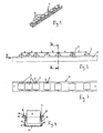
- Fig. 1 shown is a perspective view of a runway, which consists of a channel-shaped rail 1 and several, in the direction of the rail 1 successively arranged rolling elements 2, which in about Fig. 1 not to be recognized rotary axes are rotatably mounted.
- the rolling elements 2 have, viewed over the length of the rail 1, different distances, cf. Fig. 2 , In the area of the feed side, ie the side on which the stored goods are received, the rolling bodies 2 are compressed, ie the distances a are denser than the distances b, which in turn are denser than the subsequent distances c.
- the roll density can also be increased in the unloading area and in other sections of the runway where the stored material lingers for a long time.
- the profile rail 1 has a flat bottom 11 and two side walls 12 that are angled upwards away from it.
- a sheet metal part which is made for example by multiple bending, folding, deep drawing or combinations of these and other known methods of sheet metal forming.
- the side walls 12 of the profile 1 have at their upper ends bearing openings 4, in which transverse to the rail 1, the axes of rotation 3 of the rolling bodies 2 are arranged.
- the bearing openings 4 may be designed as in relation to FIG. 8 is described.
- the side walls 12 may be designed so that they do not extend at right angles to the floor 11, but slightly inclined inwards.
- the inclination angle ⁇ is about 85 °. In other modifications of this embodiment, the inclination angle ⁇ may be between 80 ° and 90 ° or between 60 ° and 97 °.
- the side walls in this embodiment are substantially planar and are known directly near the bottom.
- the side walls 12 between the bottom 11 and the Upper region of a kink 16 in the longitudinal direction are not substantially flat due to the Knicks.
- the side walls 12, starting from the base 11 initially extend substantially at right angles to the top and are folded inwards only at a distance above the bottom. In both embodiments, the distance A between the free ends of the side walls 12 is smaller than the width B of the bottom 11, see.
- sections 14 may, for example, extend as substantially horizontal sections 14.
- a part of the bearing opening 4 may be provided in the region of the portion 14, wherein the distance between the edges of the two corresponding bearing openings 4 in the region of the opposite portions 14 on the opposite side walls 12 may be smaller than the length L of the axis of rotation, when the axes of rotation. 3 are inserted into the bearing openings 4.
- the side walls After inserting the axes of rotation 3, the side walls, for example elastically springing back, can be brought into a position in which the distance between the edges of the two corresponding bearing openings 4 in the region of the opposite portions 14 is smaller than the length L of the axis of rotation.
- the axis of rotation can be held in the bearing openings 4 via the horizontal sections 14 in the transverse direction to the axis of rotation 3 and secured.
- Each of the horizontal sections 14 is followed by further sections 15 extending transversely to the axis of rotation.
- These sections may e.g. be formed as vertical sections which extend substantially vertically downwards.
- Such portions 15 may rest with a small gap at the ends of the axes of rotation 3 when the axes of rotation 3 are inserted into the profile. It is also conceivable that the portions 15 rest against the ends of the axes of rotation 3 elastically biased.
- the respective axes of rotation 3 can be maintained at a sliding out or falling out in the axial direction of the axes of rotation 3 from the stored position.
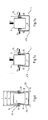
- a profile is shown in which the side walls 12 extend from the ground at right angles angled upwards. Above the axes 3, portions of the side walls each extend in the direction of the center of the profile rail. Another section 15 connects each running down.
- the bearing openings 4 are arranged at these last sections.
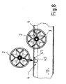
- the bearing openings can be as in Fig. 8 be designed represented, according to which the upper portion of the bearing opening 4 has an insertion bevel 41 and extends inclined towards a lower bearing shell 42.
- the axis of rotation 3 comes to lie on both sides of the rail 1 in a bearing shell 42.
- Fig. 5 is to see the design of the provided in the side wall 12 bearing opening 4 in a perspective view on the left.
- the opening 4 extends from above into the material of the side wall 12.
- the bearing opening 4 is formed overall in the manner of a depression which extends from the upper free edge of the side wall 12 in the plane of the side wall 12 in the direction of the bottom 11.
- the provided with the rotation axis 3 roll 2 can therefore be lowered from above, ie substantially in the direction of the side walls 12 in the opening 4 and received there.
- the bearing opening 4 has a geometry which allows a simple insertion of the rolling body 2 and the rotation axis 3 from above.
- the width of the bearing opening 4 ie, their extension in the direction of the rail 1, greater than in the lower, cup-shaped region.
- the upper region of the bearing opening 4 has an insertion bevel 41 which extends inclined in the direction of a lower bearing shell 42.
- the diameter of the bearing shell 42 substantially corresponds to the diameter of the rotation axis 3, with a certain excess, in order to achieve a tilt-free slipping in of the rotation axis 3.
- the insertion bevel 41 is of an overall ramp-shaped inclined geometry and forms a kind of insertion funnel for the rotation axis 3. Die in Fig. 8 Roller 2 shown on the right is shown in the end position, in which the axis of rotation 3 has assumed its position within the bearing shell 42 of the opening 4.
- the axis of rotation 3 is secured in position via a securing means 13. Details of the position assurance are in the 6 and 7 to recognize the profile of the rail 1 on the one hand in the unloaded and on the other hand in the loaded state to recognize.
- a securing means 13 serves a double fold in the region of the upper end of the side wall 12, which consists of two sections 14, 15.
- the one section 14 extends substantially in the direction of the axis of rotation 3, whereas the other section 15 extends transversely to the axial direction of the axis of rotation 3 and faces the free end of the axis of rotation 3 frontally.
- the axis 3 within the bearing opening 4 with a certain play in the axial direction is movable back and forth. This game is no longer available with circulation of a sufficiently heavy stored goods, as in Fig. 7a is shown.
- the pair of the two opposing openings 4 has an opening W, which is smaller than the length L of the rotation axis 3.
- the upper ends of the side walls 12 first widened by spreading, ie from each other must be bent until the opening width W of the axial length L corresponds, so that the rotation axis 3 can be inserted from above into the bearing openings 4. Then, the side walls 12 spring back into their initial position, which in addition to the axial securing by the sections 15 in the radially upwardly facing direction of the axis of rotation 3 via the sections 14 a position assurance is achieved.
- the rail according to the embodiment in the FIGS. 6 and 7 is dimensioned so that the opening width W then corresponds to the axial length L of the rotation axis 3, when the side walls 12 with the bottom 11 form an angle of 90 °.
- FIG. 9 an embodiment of a production line is shown, which is suitable for carrying out a possible manufacturing method for producing a runway according to the invention.
- the production of the rail 1 and in the upper part of the production of the rolling body 2 and its placement is shown with the rotation axis 3, after which the arrangement of the rollers 2 takes place on the rail 1.
- the production of the rail is carried out starting from a wound on a roll 100, metallic strip material 101, which unwound and subsequently by a plurality of rollers 102 exhibiting, the strip material smoothing straightener 103 and a device 104 is guided to a punching device 105, the pressing tool 106 the Bearing openings 4 punched out of the band-shaped material 101.
- the bearing openings can be automated according to the requirements of the finished runway, which correspond to the intended use and location of the finished runway, be mounted at different distances from each other. Subsequently, in a profiling machine 107, the channel-shaped cross section of the profile rail 1 is produced with the securing means 13 provided at the free ends of the side walls 12.
- the production of the rolls 2 made of a plastic material, for example by injection molding or extrusion in a corresponding device 108 runs.
- the bolt-shaped rotation axes 3 are produced and subsequently in a placement machine 110 in the rolling body. 2 plugged in.
- the rolling elements 2 are used together with the axes of rotation 3 in a mounting device 111 in the bearing openings 4 of the profile 1, as previously described in detail.
- a further cutting device 112 is followed by a marking and then cutting the profile rails, after which these according to a last method step means suitable transport devices 113 are transported away.
Landscapes
- Engineering & Computer Science (AREA)
- Mechanical Engineering (AREA)
- Rollers For Roller Conveyors For Transfer (AREA)
- Bearings For Parts Moving Linearly (AREA)
- Rolling Contact Bearings (AREA)
Claims (16)
- Convoyeur à rouleaux servant au transport de produits à stocker, comprenant- un rail profilé (1), qui présente un fond (11) et deux parois latérales (12) s'étendant selon un certain angle par rapport au fond (11), sachant que les parois latérales (12) sont réalisées de telle manière qu'elles tendent sous l'effet d'une force orientée en direction du fond (11) à pivoter l'une par rapport à l'autre,- plusieurs corps de rouleaux (2), qui sont logés de manière à pouvoir tourner par l'intermédiaire d'axes de rotation (3) dans des ouvertures de palier (4) des parois latérales (12),- et des moyens (13) servant à fixer les axes de rotation (3) dans les ouvertures de palier (4),sachant que les ouvertures de palier (4) sont réalisées sous la forme de cavités s'étendant depuis l'extrémité libre des parois latérales (12) en direction du fond (12),
caractérisé en ce que
la distance (A) entre les extrémités libres des parois latérales (12) est plus petite que la largeur (B) du fond (11),
les parois latérales (12) forment avec le fond (11) au moins par endroits un angle (a) inférieur à 90°,
et des moyens de fixation (13) sont prévus, lesquels sont réalisés sous la forme de doubles chanfreins d'un seul tenant des parois latérales (12), sachant qu'un tronçon (14) du moyen de fixation (13) s'étend en direction de l'axe de rotation (3) vers l'extérieur, tandis que l'autre tronçon (15) du moyen de fixation (13) s'étend de manière transversale par rapport à la direction axiale de l'axe de rotation (3) et fait face côté frontal aux extrémités libres (31) des axes de rotation (3). - Convoyeur à rouleaux selon la revendication 1, dans le cadre duquel les parois latérales (12) forment sur toute leur hauteur avec le fond (11) un angle (a) inférieur à 90°, de préférence inférieur à 85°.
- Convoyeur à rouleaux selon la revendication 1 ou 2, dans le cadre duquel le rail profilé (1) est réalisé de telle manière que les tronçons (14) viennent s'appuyer contre les extrémités libres (31) des axes de rotation (3) lors d'un mouvement de pivotement des parois latérales (12).
- Convoyeur à rouleaux selon l'une quelconque des revendications précédentes, dans le cadre duquel la largeur de l'ouverture de palier (4) dans la zone de l'extrémité libre de la paroi latérale (12) est plus grande que le diamètre de l'axe de rotation (3), et/ou sachant que l'ouverture de palier (4) est réalisée de manière à être plus étroite en direction du fond (11) que dans la zone de l'extrémité libre de la paroi latérale (12).
- Convoyeur à rouleaux selon la revendication 4, dans le cadre duquel l'ouverture de palier (4) présente un biseau d'insertion (41) et une coque de palier (42) correspondant essentiellement au diamètre de l'axe de rotation (3).
- Convoyeur à rouleaux selon l'une quelconque des revendications précédentes, dans le cadre duquel deux ouvertures de palier (4) se faisant face présentent une largeur d'ouverture (W) qui est inférieure à la longueur (L) de l'axe de rotation (3).
- Procédé servant à fabriquer un convoyeur à rouleaux servant au transport de produits à stocker, comprenant les étapes suivantes consistant à :- mettre à disposition plusieurs corps de rouleaux (2) dotés d'axes de rotation (3),- mettre à disposition un rail profilé (1), qui présente un fond (11) et deux parois latérales (12) s'étendant selon un certain angle par rapport au fond (11), sachant que les parois latérales (12) sont réalisées de telle sorte qu'elles tendent sous l'effet d'une force orientée en direction du fond (11) à pivoter l'une par rapport à l'autre, sachant que :- les parois latérales (12) présentent des ouvertures de palier (4) et des moyens (13) servant à fixer les axes de rotation (3) dans les ouvertures de palier (4),- la distance (A) entre les extrémités libres des parois latérales (12) est inférieure à la largeur (B) du fond (11), et- les parois latérales (12) forment avec le fond (11) au moins par endroits un angle (a) inférieur à 90°,- mettre à disposition des moyens de fixation (13), qui sont réalisés sous la forme de doubles chanfreins d'un seul tenant des parois latérales (12), sachant qu'un tronçon (14) du moyen de fixation (13) s'étend en direction de l'axe de rotation (3) vers l'extérieur, tandis que l'autre tronçon (15) du moyen de fixation (13) s'étend de manière transversale par rapport à la direction axiale de l'axe de rotation (3) et fait face côté frontal aux extrémités libres (31) des axes de rotation (3), et- insérer les axes de rotation (3) dans des ouvertures de palier (4) des parois latérales (12), sachant que les corps de rouleaux (2) sont insérés dans les ouvertures de palier (4) conjointement avec les axes de rotation (3) depuis le dessus des ouvertures de palier (4) dans une direction d'insertion orientée vers le bas en direction du fond du rail profilé.
- Procédé selon la revendication 7, dans le cadre duquel la largeur d'ouverture (W) des ouvertures de palier (4) se faisant face est agrandie temporairement avant l'étape consistant à insérer les axes de rotation par écartement des parois latérales (12), et dans le cadre duquel la largeur d'ouverture (W) des ouvertures de palier (4) se faisant face est à nouveau réduite après l'étape consistant à insérer les axes de rotation dans les ouvertures de palier.
- Procédé selon la revendication 8, sachant que l'écartement des parois latérales (12) est effectué dans une zone délimitée localement dans la direction longitudinale du rail profilé, dans laquelle zone sont insérés les rouleaux.
- Procédé selon l'une quelconque des revendications 7 à 9, sachant que le procédé présente en outre une étape consistant à pratiquer les ouvertures de palier, par l'intermédiaire de laquelle les ouvertures de palier (4) sont produites dans une tôle non profilée ou dans une tôle déjà profilée.
- Procédé selon l'une quelconque des revendications 7 à 10, sachant que le procédé présente en outre une étape de profilage, qui précède l'insertion des rouleaux.
- Procédé selon l'une quelconque des revendications 10 à 11, dans le cadre duquel l'action de pratiquer les diverses ouvertures de palier est effectuée de manière cadencée, l'insertion des divers rouleaux dans les ouvertures de palier est effectuée de manière cadencée, l'action de pratiquer les diverses ouvertures de palier et l'insertion des divers rouleaux, lesquelles sont effectuées de manière cadencée, dépendent l'une de l'autre.
- Procédé selon l'une quelconque des revendications 7 à 12, servant à fabriquer un convoyeur à rouleaux servant au transport de produits à stocker, comprenant les étapes suivantes consistant à :- déterminer diverses distances entre les corps de rouleaux pour le convoyeur à rouleaux à fabriquer,- fabriquer un rail profilé (1) avec des ouvertures de palier (4), lesquelles présentent les unes par rapport aux autres dans la direction longitudinale du rail profilé (1) diverses distances (a, b, c), qui correspondent à des distances données entre les corps de rouleaux,- mettre à disposition plusieurs corps de rouleaux (2) dotés d'axes de rotation (3),- insérer les axes de rotation (3) dans les ouvertures de palier (4).
- Chaîne de production servant à fabriquer un convoyeur à rouleaux selon l'une quelconque des revendications 1 à 6 en utilisant un procédé selon l'une quelconque des revendications 7 à 12.
- Chaîne de production selon la revendication 14, comprenant un dispositif d'estampage (105) servant à estamper les ouvertures de palier (4) et une machine de mise en forme des profilés (107) servant à mettre en forme un matériau en bande métallique (101).
- Chaîne de production selon la revendication 15, comprenant en outre un mécanisme d'orientation (103) servant à orienter de manière rectiligne un matériau en bande métallique (101), et/ou un dispositif d'implantation (111) servant à insérer les rouleaux dans les ouvertures de palier (4) et/ou un dispositif de découpe en longueur (112) servant à découper en longueur les convoyeurs à rouleaux (1) implantés.
Priority Applications (2)
| Application Number | Priority Date | Filing Date | Title |
|---|---|---|---|
| EP09793889.8A EP2313331B1 (fr) | 2008-07-09 | 2009-07-09 | Convoyeur a rouleaux avec rail profile |
| PL09793889T PL2313331T3 (pl) | 2008-07-09 | 2009-07-09 | Przenośnik rolkowy z szyną profilową |
Applications Claiming Priority (3)
| Application Number | Priority Date | Filing Date | Title |
|---|---|---|---|
| EP08290677A EP2143668A1 (fr) | 2008-07-09 | 2008-07-09 | Bande de rouleaux dotée de rails profilés |
| EP09793889.8A EP2313331B1 (fr) | 2008-07-09 | 2009-07-09 | Convoyeur a rouleaux avec rail profile |
| PCT/EP2009/004990 WO2010003674A1 (fr) | 2008-07-09 | 2009-07-09 | Convoyeur à rouleaux avec rail profilé |
Publications (2)
| Publication Number | Publication Date |
|---|---|
| EP2313331A1 EP2313331A1 (fr) | 2011-04-27 |
| EP2313331B1 true EP2313331B1 (fr) | 2013-09-11 |
Family
ID=40297825
Family Applications (2)
| Application Number | Title | Priority Date | Filing Date |
|---|---|---|---|
| EP08290677A Withdrawn EP2143668A1 (fr) | 2008-07-09 | 2008-07-09 | Bande de rouleaux dotée de rails profilés |
| EP09793889.8A Active EP2313331B1 (fr) | 2008-07-09 | 2009-07-09 | Convoyeur a rouleaux avec rail profile |
Family Applications Before (1)
| Application Number | Title | Priority Date | Filing Date |
|---|---|---|---|
| EP08290677A Withdrawn EP2143668A1 (fr) | 2008-07-09 | 2008-07-09 | Bande de rouleaux dotée de rails profilés |
Country Status (10)
| Country | Link |
|---|---|
| US (1) | US9981805B2 (fr) |
| EP (2) | EP2143668A1 (fr) |
| JP (1) | JP5628798B2 (fr) |
| CN (1) | CN102089226A (fr) |
| BR (1) | BRPI0915739B1 (fr) |
| DK (1) | DK2313331T3 (fr) |
| ES (1) | ES2431585T3 (fr) |
| PL (1) | PL2313331T3 (fr) |
| RU (1) | RU2011103718A (fr) |
| WO (1) | WO2010003674A1 (fr) |
Families Citing this family (13)
| Publication number | Priority date | Publication date | Assignee | Title |
|---|---|---|---|---|
| RU2495809C2 (ru) * | 2011-12-19 | 2013-10-20 | Общество с ограниченной ответственностью "Торговый дом "Пакверк" | Рольганг упаковочной линии и ролик рольганга |
| ES1077073Y (es) * | 2012-05-15 | 2012-08-29 | Merino Casajuana Carles | Carril para el transporte de mercancias |
| DE202013002290U1 (de) | 2013-03-11 | 2014-06-12 | Interroll-Holding Ag | Förderrolle mit Versteifungselement |
| JP6424447B2 (ja) * | 2014-03-28 | 2018-11-21 | 東洋製罐グループホールディングス株式会社 | 細胞培養方法、及び細胞培養システム |
| JP6317625B2 (ja) * | 2014-05-22 | 2018-04-25 | 一夫 金子 | 移動補助装置 |
| CN104401641B (zh) * | 2014-11-13 | 2017-07-25 | 江苏新海科技发展有限公司 | 流水线用运输滚动装置 |
| CN104401643B (zh) * | 2014-11-13 | 2017-07-25 | 盐城市双利电机有限公司 | 流水线用运输滚动装置用滚动架 |
| KR101938448B1 (ko) * | 2015-09-30 | 2019-04-11 | 임흥순 | 롤러 트랙의 자동 롤러 결합 장치 |
| JP5986282B1 (ja) * | 2015-11-18 | 2016-09-06 | 大口 元気 | ホイールコンベア |
| CN205366804U (zh) * | 2015-12-29 | 2016-07-06 | 广东欧富隆自动货架科技有限公司 | 一种新型滚轴自动传输装置 |
| EP3428079B1 (fr) * | 2017-07-14 | 2019-12-25 | MULTIVAC Sepp Haggenmüller SE & Co. KG | Emboutisseuse d'emballage comprenant un support d'emballage souple |
| CN107741686B (zh) * | 2017-10-25 | 2020-06-09 | 武汉华星光电技术有限公司 | 一种显影机及其传动装置 |
| CN112916778A (zh) * | 2021-01-25 | 2021-06-08 | 北京机电研究所有限公司 | 一种超大型辊锻件辊锻过程中接料架设计 |
Family Cites Families (26)
| Publication number | Priority date | Publication date | Assignee | Title |
|---|---|---|---|---|
| US2827153A (en) * | 1954-04-07 | 1958-03-18 | Rapids Standard Co Inc | Powered roll conveyors |
| US2964155A (en) * | 1958-12-26 | 1960-12-13 | Leonard B Flowers | Conveyor |
| US3420348A (en) | 1967-02-13 | 1969-01-07 | Leona Caudell | Storage rack rail member |
| US3586142A (en) * | 1969-05-01 | 1971-06-22 | Rapistan Inc | Rail for racks and the like |
| FR2080846B1 (fr) * | 1970-02-05 | 1974-05-03 | Mills Const Sa | |
| US4054195A (en) * | 1975-05-19 | 1977-10-18 | Mallard Manufacturing Corporation | Roller conveyor |
| US4239100A (en) * | 1978-03-02 | 1980-12-16 | Unarco Industries, Inc. | Package flow system |
| SU1285290A1 (ru) | 1984-10-08 | 1987-01-23 | Украинский Государственный Институт По Проектированию Металлургических Заводов | Проходна печь дл нагрева длинномерных цилиндрических изделий |
| US4681203A (en) * | 1985-11-22 | 1987-07-21 | Omniquest, Inc. | Multi-track gravity conveyor |
| US4969548A (en) * | 1988-04-27 | 1990-11-13 | Kornylak Corporation | Compression set limiting gravity conveyor |
| US5056642A (en) * | 1990-09-13 | 1991-10-15 | Unarco Industries, Inc. | Roller track for storage rack, roller conveyor, or similar apparatus |
| JPH05238527A (ja) * | 1992-02-26 | 1993-09-17 | Daifuku Co Ltd | ローラコンベヤ |
| DE4235931C2 (de) | 1992-10-23 | 2001-06-21 | Sms Demag Ag | Richtmaschine zum Richten eines Bleches oder Blechbandes |
| US5476167A (en) * | 1993-12-23 | 1995-12-19 | Unarco Material Handling, Inc. | Roller track having externally secured spindles for storage rack, roller conveyor, or similar apparatus |
| DE9410424U1 (de) * | 1994-06-28 | 1994-08-25 | Schmale, Erhard, 34414 Warburg | Rollenleiste |
| FR2756263B1 (fr) * | 1996-11-28 | 1999-02-12 | Sipa Roller | Rail a galets |
| KR200215858Y1 (ko) | 1999-03-17 | 2001-03-15 | 배점규 | 로울러유니트 |
| US6230908B1 (en) * | 1999-09-01 | 2001-05-15 | Dell Usa, L.P. | Flow rack with reverse flow limiting device |
| GB2357272B (en) * | 1999-12-14 | 2003-01-22 | Flowstore Systems Plc | Roller track |
| KR100396543B1 (ko) | 2000-08-23 | 2003-09-02 | 삼성전자주식회사 | 텔레비전 방송에서의 배너 광고 서비스 제공 시스템 및 방법 |
| JP2003020106A (ja) * | 2001-07-09 | 2003-01-21 | Sanshin Kinzoku Kogyo Kk | ラック用レール |
| US6523664B2 (en) * | 2001-07-25 | 2003-02-25 | B-O-F Corporation | Rollers and track for gravity fed shelving apparatus |
| KR200285094Y1 (ko) | 2002-05-23 | 2002-08-13 | 곽형근 | 금속골판 지붕재의 형상과 동일한 단면 형상을 갖는용마루 판 |
| JP3802521B2 (ja) | 2003-09-02 | 2006-07-26 | ソニー株式会社 | 符号化装置、符号化制御方法及び符号化制御プログラム |
| US7147096B2 (en) | 2004-11-01 | 2006-12-12 | Creform Corporation | Wheeled conveyor rail |
| SE535479C2 (sv) * | 2011-01-28 | 2012-08-21 | Flexqube Ab | Teleskopisk rullbana |
-
2008
- 2008-07-09 EP EP08290677A patent/EP2143668A1/fr not_active Withdrawn
-
2009
- 2009-07-09 CN CN2009801268804A patent/CN102089226A/zh active Pending
- 2009-07-09 BR BRPI0915739-5A patent/BRPI0915739B1/pt not_active IP Right Cessation
- 2009-07-09 PL PL09793889T patent/PL2313331T3/pl unknown
- 2009-07-09 RU RU2011103718/11A patent/RU2011103718A/ru not_active Application Discontinuation
- 2009-07-09 US US13/003,402 patent/US9981805B2/en active Active
- 2009-07-09 ES ES09793889T patent/ES2431585T3/es active Active
- 2009-07-09 JP JP2011517029A patent/JP5628798B2/ja not_active Expired - Fee Related
- 2009-07-09 DK DK09793889.8T patent/DK2313331T3/da active
- 2009-07-09 EP EP09793889.8A patent/EP2313331B1/fr active Active
- 2009-07-09 WO PCT/EP2009/004990 patent/WO2010003674A1/fr not_active Ceased
Also Published As
| Publication number | Publication date |
|---|---|
| US9981805B2 (en) | 2018-05-29 |
| BRPI0915739A2 (pt) | 2015-10-27 |
| EP2143668A1 (fr) | 2010-01-13 |
| BRPI0915739B1 (pt) | 2019-03-19 |
| DK2313331T3 (da) | 2013-11-04 |
| WO2010003674A1 (fr) | 2010-01-14 |
| EP2313331A1 (fr) | 2011-04-27 |
| JP5628798B2 (ja) | 2014-11-19 |
| JP2011527273A (ja) | 2011-10-27 |
| US20120181141A1 (en) | 2012-07-19 |
| CN102089226A (zh) | 2011-06-08 |
| RU2011103718A (ru) | 2012-08-20 |
| ES2431585T3 (es) | 2013-11-27 |
| PL2313331T3 (pl) | 2013-12-31 |
Similar Documents
| Publication | Publication Date | Title |
|---|---|---|
| EP2313331B1 (fr) | Convoyeur a rouleaux avec rail profile | |
| EP1479842B1 (fr) | Profilé creux | |
| EP2225055B1 (fr) | Dispositif et procédé de profilage par laminage à froid de profilés de hauteur variable | |
| EP3016551B1 (fr) | Élément de tablette pour une tablette d'une étagère, en particulier d'une étagère à glissière, ainsi que cadre de tablette, tablette et étagère | |
| DE602005000410T2 (de) | Rollerbahn | |
| DE102016120869A1 (de) | Regal, Lastträger hierfür und Verfahren zur Herstellung | |
| DE4215715C2 (de) | Lagerbuchse | |
| DE202011051396U1 (de) | Profilummantelungsmaschine | |
| EP2604493B1 (fr) | Les enjeux pour la construction d'un véhicule commercial | |
| EP2478235A1 (fr) | Roulement à rouleaux sphériques | |
| EP3713846B1 (fr) | Plateau pour un ascenseur de stockage | |
| WO2010124803A2 (fr) | Entrepôt à très grande hauteur, montant pour un entrepôt à très grande hauteur et procédé de fabrication du montant | |
| DE4222175C2 (de) | Wälzlagerkäfig | |
| WO2001083334A1 (fr) | Dispositif de transport d'un rouleau | |
| EP3307653B1 (fr) | Grille destinée en particulier à être utilisée en tant que tablette pour des rayonnages à plaques ou des rayonnages pour charges lourdes | |
| EP3336048B1 (fr) | Appareil de commande de rayonnage | |
| WO1986000857A1 (fr) | Dispositif de support d'un siege coulissant dans un vehicule | |
| DE2908006A1 (de) | Foerdervorrichtung | |
| DE202012013393U1 (de) | Schienensystem | |
| DE3638580C2 (fr) | ||
| EP3239073A1 (fr) | Étagère, porte-charge associé et procédé de fabrication | |
| DE10312705B3 (de) | Kalander und Verfahren zum Ausbauen einer Unterwalze aus einem Kalander | |
| DE102024002307B3 (de) | Transportwagensystem mit Stapelsicherung | |
| DE102019129268A1 (de) | Rollenbahn und Verfahren zur Herstellung einer solchen | |
| CH660413A5 (de) | Rollenlager zur auflagerung von heiss- oder kaltgehenden rohrleitungen. |
Legal Events
| Date | Code | Title | Description |
|---|---|---|---|
| PUAI | Public reference made under article 153(3) epc to a published international application that has entered the european phase |
Free format text: ORIGINAL CODE: 0009012 |
|
| 17P | Request for examination filed |
Effective date: 20110203 |
|
| AK | Designated contracting states |
Kind code of ref document: A1 Designated state(s): AT BE BG CH CY CZ DE DK EE ES FI FR GB GR HR HU IE IS IT LI LT LU LV MC MK MT NL NO PL PT RO SE SI SK SM TR |
|
| AX | Request for extension of the european patent |
Extension state: AL BA RS |
|
| DAX | Request for extension of the european patent (deleted) | ||
| 17Q | First examination report despatched |
Effective date: 20130123 |
|
| GRAP | Despatch of communication of intention to grant a patent |
Free format text: ORIGINAL CODE: EPIDOSNIGR1 |
|
| INTG | Intention to grant announced |
Effective date: 20130506 |
|
| RIN1 | Information on inventor provided before grant (corrected) |
Inventor name: SEJOURNE, JEROME Inventor name: REYMOND, BERTRAND |
|
| GRAS | Grant fee paid |
Free format text: ORIGINAL CODE: EPIDOSNIGR3 |
|
| RAP1 | Party data changed (applicant data changed or rights of an application transferred) |
Owner name: INTERROLL HOLDING AG |
|
| GRAA | (expected) grant |
Free format text: ORIGINAL CODE: 0009210 |
|
| RAP1 | Party data changed (applicant data changed or rights of an application transferred) |
Owner name: INTERROLL HOLDING AG |
|
| AK | Designated contracting states |
Kind code of ref document: B1 Designated state(s): AT BE BG CH CY CZ DE DK EE ES FI FR GB GR HR HU IE IS IT LI LT LU LV MC MK MT NL NO PL PT RO SE SI SK SM TR |
|
| REG | Reference to a national code |
Ref country code: GB Ref legal event code: FG4D Free format text: NOT ENGLISH |
|
| REG | Reference to a national code |
Ref country code: CH Ref legal event code: NV Representative=s name: PATENTANWAELTE SCHAAD, BALASS, MENZL AND PARTN, CH Ref country code: CH Ref legal event code: EP |
|
| REG | Reference to a national code |
Ref country code: AT Ref legal event code: REF Ref document number: 631493 Country of ref document: AT Kind code of ref document: T Effective date: 20130915 |
|
| REG | Reference to a national code |
Ref country code: IE Ref legal event code: FG4D Free format text: LANGUAGE OF EP DOCUMENT: GERMAN |
|
| REG | Reference to a national code |
Ref country code: DK Ref legal event code: T3 Effective date: 20131029 Ref country code: DK Ref legal event code: T3 |
|
| REG | Reference to a national code |
Ref country code: DE Ref legal event code: R096 Ref document number: 502009008011 Country of ref document: DE Effective date: 20131107 |
|
| REG | Reference to a national code |
Ref country code: ES Ref legal event code: FG2A Ref document number: 2431585 Country of ref document: ES Kind code of ref document: T3 Effective date: 20131127 |
|
| REG | Reference to a national code |
Ref country code: NL Ref legal event code: T3 |
|
| REG | Reference to a national code |
Ref country code: PL Ref legal event code: T3 |
|
| PG25 | Lapsed in a contracting state [announced via postgrant information from national office to epo] |
Ref country code: NO Free format text: LAPSE BECAUSE OF FAILURE TO SUBMIT A TRANSLATION OF THE DESCRIPTION OR TO PAY THE FEE WITHIN THE PRESCRIBED TIME-LIMIT Effective date: 20131211 Ref country code: SE Free format text: LAPSE BECAUSE OF FAILURE TO SUBMIT A TRANSLATION OF THE DESCRIPTION OR TO PAY THE FEE WITHIN THE PRESCRIBED TIME-LIMIT Effective date: 20130911 Ref country code: CY Free format text: LAPSE BECAUSE OF FAILURE TO SUBMIT A TRANSLATION OF THE DESCRIPTION OR TO PAY THE FEE WITHIN THE PRESCRIBED TIME-LIMIT Effective date: 20130717 Ref country code: LT Free format text: LAPSE BECAUSE OF FAILURE TO SUBMIT A TRANSLATION OF THE DESCRIPTION OR TO PAY THE FEE WITHIN THE PRESCRIBED TIME-LIMIT Effective date: 20130911 Ref country code: HR Free format text: LAPSE BECAUSE OF FAILURE TO SUBMIT A TRANSLATION OF THE DESCRIPTION OR TO PAY THE FEE WITHIN THE PRESCRIBED TIME-LIMIT Effective date: 20130911 |
|
| REG | Reference to a national code |
Ref country code: LT Ref legal event code: MG4D |
|
| PG25 | Lapsed in a contracting state [announced via postgrant information from national office to epo] |
Ref country code: GR Free format text: LAPSE BECAUSE OF FAILURE TO SUBMIT A TRANSLATION OF THE DESCRIPTION OR TO PAY THE FEE WITHIN THE PRESCRIBED TIME-LIMIT Effective date: 20131212 Ref country code: LV Free format text: LAPSE BECAUSE OF FAILURE TO SUBMIT A TRANSLATION OF THE DESCRIPTION OR TO PAY THE FEE WITHIN THE PRESCRIBED TIME-LIMIT Effective date: 20130911 Ref country code: FI Free format text: LAPSE BECAUSE OF FAILURE TO SUBMIT A TRANSLATION OF THE DESCRIPTION OR TO PAY THE FEE WITHIN THE PRESCRIBED TIME-LIMIT Effective date: 20130911 Ref country code: SI Free format text: LAPSE BECAUSE OF FAILURE TO SUBMIT A TRANSLATION OF THE DESCRIPTION OR TO PAY THE FEE WITHIN THE PRESCRIBED TIME-LIMIT Effective date: 20130911 |
|
| PG25 | Lapsed in a contracting state [announced via postgrant information from national office to epo] |
Ref country code: CY Free format text: LAPSE BECAUSE OF FAILURE TO SUBMIT A TRANSLATION OF THE DESCRIPTION OR TO PAY THE FEE WITHIN THE PRESCRIBED TIME-LIMIT Effective date: 20130911 |
|
| PG25 | Lapsed in a contracting state [announced via postgrant information from national office to epo] |
Ref country code: EE Free format text: LAPSE BECAUSE OF FAILURE TO SUBMIT A TRANSLATION OF THE DESCRIPTION OR TO PAY THE FEE WITHIN THE PRESCRIBED TIME-LIMIT Effective date: 20130911 Ref country code: SK Free format text: LAPSE BECAUSE OF FAILURE TO SUBMIT A TRANSLATION OF THE DESCRIPTION OR TO PAY THE FEE WITHIN THE PRESCRIBED TIME-LIMIT Effective date: 20130911 Ref country code: RO Free format text: LAPSE BECAUSE OF FAILURE TO SUBMIT A TRANSLATION OF THE DESCRIPTION OR TO PAY THE FEE WITHIN THE PRESCRIBED TIME-LIMIT Effective date: 20130911 Ref country code: IS Free format text: LAPSE BECAUSE OF FAILURE TO SUBMIT A TRANSLATION OF THE DESCRIPTION OR TO PAY THE FEE WITHIN THE PRESCRIBED TIME-LIMIT Effective date: 20140111 |
|
| REG | Reference to a national code |
Ref country code: DE Ref legal event code: R097 Ref document number: 502009008011 Country of ref document: DE |
|
| PG25 | Lapsed in a contracting state [announced via postgrant information from national office to epo] |
Ref country code: PT Free format text: LAPSE BECAUSE OF FAILURE TO SUBMIT A TRANSLATION OF THE DESCRIPTION OR TO PAY THE FEE WITHIN THE PRESCRIBED TIME-LIMIT Effective date: 20140113 |
|
| PLBE | No opposition filed within time limit |
Free format text: ORIGINAL CODE: 0009261 |
|
| STAA | Information on the status of an ep patent application or granted ep patent |
Free format text: STATUS: NO OPPOSITION FILED WITHIN TIME LIMIT |
|
| 26N | No opposition filed |
Effective date: 20140612 |
|
| REG | Reference to a national code |
Ref country code: DE Ref legal event code: R097 Ref document number: 502009008011 Country of ref document: DE Effective date: 20140612 |
|
| PG25 | Lapsed in a contracting state [announced via postgrant information from national office to epo] |
Ref country code: LU Free format text: LAPSE BECAUSE OF FAILURE TO SUBMIT A TRANSLATION OF THE DESCRIPTION OR TO PAY THE FEE WITHIN THE PRESCRIBED TIME-LIMIT Effective date: 20140709 |
|
| REG | Reference to a national code |
Ref country code: IE Ref legal event code: MM4A |
|
| PG25 | Lapsed in a contracting state [announced via postgrant information from national office to epo] |
Ref country code: IE Free format text: LAPSE BECAUSE OF NON-PAYMENT OF DUE FEES Effective date: 20140709 |
|
| PG25 | Lapsed in a contracting state [announced via postgrant information from national office to epo] |
Ref country code: MC Free format text: LAPSE BECAUSE OF FAILURE TO SUBMIT A TRANSLATION OF THE DESCRIPTION OR TO PAY THE FEE WITHIN THE PRESCRIBED TIME-LIMIT Effective date: 20130911 Ref country code: SM Free format text: LAPSE BECAUSE OF FAILURE TO SUBMIT A TRANSLATION OF THE DESCRIPTION OR TO PAY THE FEE WITHIN THE PRESCRIBED TIME-LIMIT Effective date: 20130911 |
|
| REG | Reference to a national code |
Ref country code: FR Ref legal event code: PLFP Year of fee payment: 8 |
|
| PG25 | Lapsed in a contracting state [announced via postgrant information from national office to epo] |
Ref country code: MT Free format text: LAPSE BECAUSE OF FAILURE TO SUBMIT A TRANSLATION OF THE DESCRIPTION OR TO PAY THE FEE WITHIN THE PRESCRIBED TIME-LIMIT Effective date: 20130911 Ref country code: BG Free format text: LAPSE BECAUSE OF FAILURE TO SUBMIT A TRANSLATION OF THE DESCRIPTION OR TO PAY THE FEE WITHIN THE PRESCRIBED TIME-LIMIT Effective date: 20130911 |
|
| PG25 | Lapsed in a contracting state [announced via postgrant information from national office to epo] |
Ref country code: HU Free format text: LAPSE BECAUSE OF FAILURE TO SUBMIT A TRANSLATION OF THE DESCRIPTION OR TO PAY THE FEE WITHIN THE PRESCRIBED TIME-LIMIT; INVALID AB INITIO Effective date: 20090709 Ref country code: BE Free format text: LAPSE BECAUSE OF FAILURE TO SUBMIT A TRANSLATION OF THE DESCRIPTION OR TO PAY THE FEE WITHIN THE PRESCRIBED TIME-LIMIT Effective date: 20140731 |
|
| REG | Reference to a national code |
Ref country code: FR Ref legal event code: PLFP Year of fee payment: 9 |
|
| PG25 | Lapsed in a contracting state [announced via postgrant information from national office to epo] |
Ref country code: MK Free format text: LAPSE BECAUSE OF FAILURE TO SUBMIT A TRANSLATION OF THE DESCRIPTION OR TO PAY THE FEE WITHIN THE PRESCRIBED TIME-LIMIT Effective date: 20130911 |
|
| REG | Reference to a national code |
Ref country code: FR Ref legal event code: PLFP Year of fee payment: 10 |
|
| PGFP | Annual fee paid to national office [announced via postgrant information from national office to epo] |
Ref country code: AT Payment date: 20190704 Year of fee payment: 11 |
|
| REG | Reference to a national code |
Ref country code: AT Ref legal event code: MM01 Ref document number: 631493 Country of ref document: AT Kind code of ref document: T Effective date: 20200709 |
|
| PG25 | Lapsed in a contracting state [announced via postgrant information from national office to epo] |
Ref country code: AT Free format text: LAPSE BECAUSE OF NON-PAYMENT OF DUE FEES Effective date: 20200709 |
|
| PGFP | Annual fee paid to national office [announced via postgrant information from national office to epo] |
Ref country code: TR Payment date: 20210705 Year of fee payment: 13 |
|
| PGFP | Annual fee paid to national office [announced via postgrant information from national office to epo] |
Ref country code: CZ Payment date: 20250626 Year of fee payment: 17 |
|
| PGFP | Annual fee paid to national office [announced via postgrant information from national office to epo] |
Ref country code: NL Payment date: 20250723 Year of fee payment: 17 |
|
| PGFP | Annual fee paid to national office [announced via postgrant information from national office to epo] |
Ref country code: ES Payment date: 20250819 Year of fee payment: 17 |
|
| PGFP | Annual fee paid to national office [announced via postgrant information from national office to epo] |
Ref country code: DK Payment date: 20250723 Year of fee payment: 17 Ref country code: DE Payment date: 20250722 Year of fee payment: 17 |
|
| PGFP | Annual fee paid to national office [announced via postgrant information from national office to epo] |
Ref country code: IT Payment date: 20250731 Year of fee payment: 17 |
|
| PGFP | Annual fee paid to national office [announced via postgrant information from national office to epo] |
Ref country code: GB Payment date: 20250724 Year of fee payment: 17 |
|
| PGFP | Annual fee paid to national office [announced via postgrant information from national office to epo] |
Ref country code: FR Payment date: 20250723 Year of fee payment: 17 |
|
| PGFP | Annual fee paid to national office [announced via postgrant information from national office to epo] |
Ref country code: CH Payment date: 20250801 Year of fee payment: 17 |
|
| PGFP | Annual fee paid to national office [announced via postgrant information from national office to epo] |
Ref country code: PL Payment date: 20250701 Year of fee payment: 17 |