EP2314455A1 - Imprimante thermique et procédé de formation d'images - Google Patents
Imprimante thermique et procédé de formation d'images Download PDFInfo
- Publication number
- EP2314455A1 EP2314455A1 EP10014987A EP10014987A EP2314455A1 EP 2314455 A1 EP2314455 A1 EP 2314455A1 EP 10014987 A EP10014987 A EP 10014987A EP 10014987 A EP10014987 A EP 10014987A EP 2314455 A1 EP2314455 A1 EP 2314455A1
- Authority
- EP
- European Patent Office
- Prior art keywords
- image data
- image
- printed
- produce
- processing
- Prior art date
- Legal status (The legal status is an assumption and is not a legal conclusion. Google has not performed a legal analysis and makes no representation as to the accuracy of the status listed.)
- Granted
Links
- 238000000034 method Methods 0.000 title claims description 39
- 238000012545 processing Methods 0.000 claims abstract description 137
- 238000006243 chemical reaction Methods 0.000 claims abstract description 88
- 238000009825 accumulation Methods 0.000 claims abstract description 37
- 238000012937 correction Methods 0.000 claims abstract description 37
- 239000000976 ink Substances 0.000 description 16
- 238000012546 transfer Methods 0.000 description 8
- 238000010586 diagram Methods 0.000 description 6
- 230000000694 effects Effects 0.000 description 6
- BQCADISMDOOEFD-UHFFFAOYSA-N Silver Chemical compound [Ag] BQCADISMDOOEFD-UHFFFAOYSA-N 0.000 description 4
- 239000003086 colorant Substances 0.000 description 4
- 239000011159 matrix material Substances 0.000 description 4
- 229920006289 polycarbonate film Polymers 0.000 description 4
- 229910052709 silver Inorganic materials 0.000 description 4
- 239000004332 silver Substances 0.000 description 4
- 230000000737 periodic effect Effects 0.000 description 3
- 239000000779 smoke Substances 0.000 description 3
- 238000004519 manufacturing process Methods 0.000 description 2
- 238000012986 modification Methods 0.000 description 2
- 230000004048 modification Effects 0.000 description 2
- 230000007261 regionalization Effects 0.000 description 2
- 239000000758 substrate Substances 0.000 description 2
- 230000015572 biosynthetic process Effects 0.000 description 1
- 230000006870 function Effects 0.000 description 1
- 239000000155 melt Substances 0.000 description 1
- 239000002985 plastic film Substances 0.000 description 1
Images







Classifications
-
- B—PERFORMING OPERATIONS; TRANSPORTING
- B41—PRINTING; LINING MACHINES; TYPEWRITERS; STAMPS
- B41J—TYPEWRITERS; SELECTIVE PRINTING MECHANISMS, i.e. MECHANISMS PRINTING OTHERWISE THAN FROM A FORME; CORRECTION OF TYPOGRAPHICAL ERRORS
- B41J2/00—Typewriters or selective printing mechanisms characterised by the printing or marking process for which they are designed
- B41J2/315—Typewriters or selective printing mechanisms characterised by the printing or marking process for which they are designed characterised by selective application of heat to a heat sensitive printing or impression-transfer material
- B41J2/32—Typewriters or selective printing mechanisms characterised by the printing or marking process for which they are designed characterised by selective application of heat to a heat sensitive printing or impression-transfer material using thermal heads
- B41J2/35—Typewriters or selective printing mechanisms characterised by the printing or marking process for which they are designed characterised by selective application of heat to a heat sensitive printing or impression-transfer material using thermal heads providing current or voltage to the thermal head
- B41J2/355—Control circuits for heating-element selection
- B41J2/36—Print density control
- B41J2/365—Print density control by compensation for variation in temperature
-
- B—PERFORMING OPERATIONS; TRANSPORTING
- B41—PRINTING; LINING MACHINES; TYPEWRITERS; STAMPS
- B41J—TYPEWRITERS; SELECTIVE PRINTING MECHANISMS, i.e. MECHANISMS PRINTING OTHERWISE THAN FROM A FORME; CORRECTION OF TYPOGRAPHICAL ERRORS
- B41J2/00—Typewriters or selective printing mechanisms characterised by the printing or marking process for which they are designed
- B41J2/005—Typewriters or selective printing mechanisms characterised by the printing or marking process for which they are designed characterised by bringing liquid or particles selectively into contact with a printing material
- B41J2/01—Ink jet
-
- B—PERFORMING OPERATIONS; TRANSPORTING
- B41—PRINTING; LINING MACHINES; TYPEWRITERS; STAMPS
- B41J—TYPEWRITERS; SELECTIVE PRINTING MECHANISMS, i.e. MECHANISMS PRINTING OTHERWISE THAN FROM A FORME; CORRECTION OF TYPOGRAPHICAL ERRORS
- B41J2/00—Typewriters or selective printing mechanisms characterised by the printing or marking process for which they are designed
- B41J2/315—Typewriters or selective printing mechanisms characterised by the printing or marking process for which they are designed characterised by selective application of heat to a heat sensitive printing or impression-transfer material
- B41J2/32—Typewriters or selective printing mechanisms characterised by the printing or marking process for which they are designed characterised by selective application of heat to a heat sensitive printing or impression-transfer material using thermal heads
- B41J2/35—Typewriters or selective printing mechanisms characterised by the printing or marking process for which they are designed characterised by selective application of heat to a heat sensitive printing or impression-transfer material using thermal heads providing current or voltage to the thermal head
- B41J2/355—Control circuits for heating-element selection
- B41J2/36—Print density control
Definitions
- the present invention relates to a thermal recording apparatus or the like which reduces effects of heat accumulated in a thermal head and prints highly fine hairline images and circular hairlines by a low resolution.
- a thermal printer is an apparatus which heats the back of an ink ribbon superimposed on a recording paper by means of a thermal head in order to thermally transfer the ink of the ink ribbon onto the recording paper, to thereby print an image on the paper.
- the ink ribbon is a thermal transfer sheet including a layer of thermally meltable color ink
- the recording paper is an image-receiving sheet such as a sheet of paper or a plastic sheet.
- the thermal head is a composed of a plurality of heat-generating resistors formed on a substrate in a row.
- the thermal printer includes a plurality of ink ribbons corresponding to a plurality of colors.
- the inks of the ink ribbons of the plurality of colors are transferred in a superimposed state onto the recording paper at the same position, to thereby perform color printing.
- the ink ribbons are disposed to be rotatable, and an ink ribbon to undergo thermal transfer is moved to the position of the thermal head.
- a recording-paper feed apparatus feeds the recording paper to the position of the thermal head, which is a printing position, whereby printing is effected in a predetermined image-printing area of the recording paper.
- a hairline pattern which is a pattern composed of a large number of thin lines (hairlines) extending along a specific direction.
- a method for consistently obtaining a clear hairline pattern has been known (see, for example, Patent Document 1).
- hairlines and hairline gaps are arranged on a drawing line of interest; a determination is made as to whether the hairline gaps arranged on the drawing line of interest are adjacent to the hairline gaps of a determined drawing line on which hairlines and hairline gaps have already been arranged; the drawing line of interest is treated as a determined drawing line only when none of the hairline gaps of the drawing line of interest is located adjacent to the hairline gaps of the determined drawing line; and the generation and arrangement of hairlines and hairline gaps for the drawing line of interest are performed once more when any of the hairline gaps of the drawing line of interest is located adjacent to the hairline gaps of the determined drawing line.
- the above-described first method requires complicated calculation for formation of hairlines.
- the above-described second method is peculiar to an image forming apparatus which forms a color image, in a transfer scheme or a direct scheme, by repeating an image forming process including a step (primary charging) of uniformly charging an image bearing body such as a photosensitive body or a dielectric body. Therefore, the second method cannot be applied to a thermal recording apparatus or the like.
- the present invention has been accomplished in view of such problems, and an object of the present invention is to provide a thermal recording apparatus or the like which reduces effects of heat accumulated in a thermal head and prints highly fine hairline images and circular hairlines by a low resolution.
- a first invention for achieving the above-described object is a printed matter obtained by performing shift processing for second image data, which are obtained from first image data through gradation conversion and halftone conversion, to thereby produce third image data; performing rotation processing for said third image data to thereby produce fourth image data; performing heat-accumulation correction processing for said third image data and said fourth image data to thereby produce fifth image data and sixth image data; and printing the fifth image data and the sixth image data on an object to be printed by a thermal recording apparatus including a thermal head.
- finer hairlines can be printed at a low resolution.
- a second invention is a thermal recording apparatus comprising means for performing shift processing for second image data, which are obtained from first image data through gradation conversion and halftone conversion, to thereby produce third image data; means for performing rotation processing for said third image data to thereby produce fourth image data; means for performing heat-accumulation correction processing for said third image data and said fourth image data to thereby produce fifth image data and sixth image data; and means for printing the fifth image data and the sixth image data on an object to be printed.
- a third invention is an image forming method comprising the steps of performing shift processing for second image data, which are obtained from first image data through gradation conversion and halftone conversion, to thereby produce third image data; performing rotation processing for said third image data to thereby produce fourth image data; performing heat-accumulation correction processing for said third image data and said fourth image data to thereby produce fifth image data and sixth image data; and printing the fifth image data and the sixth image data on an object to be printed by a thermal recording apparatus including a thermal head.
- a fourth invention is a printed matter obtained by producing first image data for forming a pattern; producing, from said first image data, second image data for forming a second pattern; performing shift processing for said second image data to thereby produce third image data; performing polar coordinate conversion for said second image data and said third image data to thereby produce fourth image data and fifth image data; performing heat-accumulation correction processing for said fourth image data and said fifth image data to thereby produce sixth image data and seventh image data; and printing said sixth image data and said seventh image data on an object to be printed by a thermal recording apparatus including a thermal head.
- a horizontal hairline pattern is produced by performing pattern definition, and another horizontal hairline pattern is produced by shifting the horizontal hairline pattern downward.
- Two circular hairlines are produced from these horizontal hairline patterns through polar coordinate conversion and combined together, whereby moiré can be reduced, and finer circular hairlines are produced.
- a fifth invention is a thermal recording apparatus comprising means for producing first image data for forming a pattern; means producing, from said first image data, second image data for forming a second pattern; means for performing shift processing for said second image data to thereby produce third image data; means for performing polar coordinate conversion for said second image data and said third image data to thereby produce fourth image data and fifth image data; means for performing heat-accumulation correction processing for said fourth image data and said fifth image data to thereby produce sixth image data and seventh image data; and means for printing said sixth image data and said seventh image data on an object to be printed.
- a sixth invention is an image forming method comprising the steps of producing first image data for forming a pattern; producing, from said first image data, second image data for forming a second pattern; performing shift processing for said second image data to thereby produce third image data; performing polar coordinate conversion for said second image data and said third image data to thereby produce fourth image data and fifth image data; performing heat-accumulation correction processing for said fourth image data and said fifth image data to thereby produce sixth image data and seventh image data; and printing said sixth image data and said seventh image data on an object to be printed by a thermal recording apparatus including a thermal head.
- a seventh invention is a printed matter obtained by producing first image data for forming a pattern; producing, from said first image data, second image data for forming a second pattern; performing polar coordinate conversion for said second image data to thereby produce third image data; performing heat-accumulation correction processing for said third image data to thereby produce fourth image data; and printing said fourth image data on an object to be printed by a thermal recording apparatus including a thermal head.
- An eighth invention is a thermal recording apparatus comprising means for producing first image data for forming a pattern; means for producing, from said first image data, second image data for forming a second pattern; means for performing polar coordinate conversion for said second image data to thereby produce third image data; means for performing heat-accumulation correction processing for said third image data to thereby produce fourth image data; and means for printing said fourth image data on an object to be printed.
- a ninth invention is an image forming method comprising the steps of producing first image data for forming a pattern; producing, from said first image data, second image data for forming a second pattern; performing polar coordinate conversion for said second image data to thereby produce third image data; performing heat-accumulation correction processing for said third image data to thereby produce fourth image data; and printing said fourth image data on an object to be printed by a thermal recording apparatus including a thermal head.
- a tenth invention is a printed matter obtained by performing polar coordinate conversion for second image data, which are obtained from first image data through gradation conversion and halftone conversion, to thereby produce third image data; performing heat-accumulation correction processing for said third image data to thereby produce fourth image data; and printing said fourth image data on an object to be printed by a thermal recording apparatus including a thermal head.
- An eleventh invention is a thermal recording apparatus comprising means for performing polar coordinate conversion for second image data, which are obtained from first image data through gradation conversion and halftone conversion, to thereby produce third image data; means for performing heat-accumulation correction processing for said third image data to thereby produce fourth image data; and means for printing said fourth image data on an object to be printed.
- a twelfth invention is an image forming method comprising the steps of performing polar coordinate conversion for second image data, which are obtained from first image data through gradation conversion and halftone conversion, to thereby produce third image data; performing heat-accumulation correction processing for said third image data to thereby produce fourth image data; and printing said fourth image data on an object to be printed by a thermal recording apparatus including a thermal head.
- thermo recording apparatus or the like which reduces effects of heat accumulated in a thermal head and prints highly fine hairline images and circular hairlines by a low resolution.
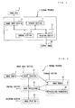
- FIG. 1 is a diagram showing the configuration of the thermal printer 1.
- the thermal printer 1 is an apparatus which heats the back of an ink ribbon (not shown) superimposed on a recording paper (not shown) by means of a thermal head (not shown) in order to thermally transfer the ink of the ink ribbon onto the recording paper, to thereby print an image on the paper.
- the thermal printer 1 includes an image input section 5, a storage section 7, a control section 9, a printing section 11, etc. which are connected together via a bus 13.
- Image data 3 to be printed are input to the image input section 5.
- the storage section 7 stores the input image data 3, data to be temporarily stored in the course of calculation, processed image data, parameters for image processing, etc.
- the control section 9 is composed of a CPU (central processing unit) which executes programs, and memory such as ROM (read only memory), RAM (random access memory), etc. for storing program instruction, data, etc.
- the control section 9 instructs the image input section 5 to read the image data 3 or process the image data 3, sends processed image data to the printing section 11, and instructs the printing section 11 to print the image data.
- the printing section 11 is composed of a thermal head including a plurality of heat-generating resistors formed in a row on a substrate; a thermal head drive section; etc. Upon receipt of image data to be printed and an instruction from the control section 9, the printing section 11 applies to the thermal head energy corresponding to each pixel value. Thus, ink at the energy-applied portion melts and adheres to recording paper, whereby an output image 15 is output.
- the printing section 11 includes four types of ink ribbons of cyan C, magenta M, yellow Y, and black K. The inks of these colors are transferred in a superimposed state so as to perform color printing.
- FIG. 2 is a diagram showing the relation between the configuration of the thermal printer 1 of FIG. 1 and the details of processing.
- the image input section 5 performs image reading 21 so as to read the image data 3.
- the image input section 5 stores the read image data into image memory 27 of the storage section 7, and simultaneously sends the image data to the control section 9.
- the control section 9 performs image processing 23 on the image data 3.
- the memory section 7 is composed of the image memory 27 for storing image data to undergo image processing, and the processing parameter memory 29 for storing parameters used when the image processing is performed. Further, although not illustrated, the storage section 7 further stores a control program, and control parameters of the printing section 11 such as the thermal head.
- Image data acquired by the thermal printer 1 and image data calculated in the course of the image processing 23 are registered in the image memory 27.
- the original image and image data obtained in the course of calculation, excluding the final image data, are not necessarily required to be left in the image memory 27.
- the processing parameter memory 29 of the storage section 7 stores parameters which are used by the image processing 23 for pattern formation, shift processing, polar coordinate conversion, heat-accumulation correction processing.
- the control section 9 performs the image processing 23.
- the image processing 23 includes various types of processing such as CMYK/RGB-gray conversion processing, gradation conversion processing, halftone conversion processing, pattern definition, horizontal hairline pattern formation, shift processing, rotation processing, polar coordinate conversion, and heat-accumulation correction processing.
- the image processing 23 performs image processing for the image data stored in the image memory 27 of the storage section 7 while using respective processing parameters stored in the processing parameter memory 29 to thereby obtain final image data.
- Image data produced in the course of the processing are stored in the image memory 27 of the storage section 7.
- the control section 9 sends the finally obtained image data to the printing section 11, which performs image printing 25.
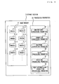
- FIG. 3 is a diagram showing the details of the storage section 7 of the thermal printer 1.
- the memory section 7 is composed of the image memory 27 for storing image data to undergo image processing, and the processing parameter memory 29 for storing parameters used when the image processing is performed. Further, although not illustrated, the storage section 7 further stores a control program, and control parameters of the printing section 11 such as the thermal head.
- the image data 3, which represent the original image acquired by the thermal printer 1, are registered in the image memory 27, as an image G 1 31-1.
- Images G 2 31-2, G 3 31-3, G 4 31-4, G 5 31-5, G 6 31-6, G 7 31-7, G 8 31-8, etc. are registered as image data calculated in the course of the image processing 23.
- the image G 1 31-1 which is the original image
- image data calculated in the course of calculation excluding the images G 7 31-7 and G 8 31-8, which serve as final image data, are not required to be left in the image memory 27.
- the processing parameter memory 29 of the storage section 7 stores a CMYK/RGB-gray conversion parameter 33, a gradation conversion parameter 35, a halftone conversion parameter 37, a shift processing parameter 39, a rotation processing parameter 41, a heat-accumulation correction processing parameter 43, etc., which are used by the image processing 23.
- FIG. 4 is a flowchart showing operation performed by the image processing 23 according to the first embodiment.
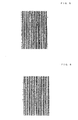
- FIG. 5 is an illustration showing an example output image in the case of gradation conversion of 100%.
- FIG. 6 is an illustration showing an example output image in the case of gradation conversion of 80%.
- FIG. 7 is an illustration showing an example output image in the case of gradation conversion of 65%.
- FIG. 8 is an illustration used for explaining a method of generating the image G 5 31-5 through lateral shift.
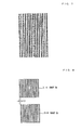
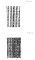
- FIG. 9 is an illustration showing an example halftone-converted image of hairlines.
- FIG. 10 is an illustration showing an example halftone-converted image of hairlines having undergone the shift processing.
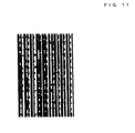
- FIG. 11 is an illustration showing an example halftone-converted image of hairlines having undergone the shift processing and the rotation processing.
- the image input section 5 of the thermal printer reads the image data 3 (step 101); and the control section 9 holds the acquired image G 1 31-1 in the image memory 27 of the storage section 7 (step 102).
- control section 9 of the thermal printer 1 executes the image processing 23. That is, the control section 9 first converts the CMYK data or RGB data of the image G 1 31-1 to gray data in accordance with the resolution of the thermal printer 1 to thereby produce the image G 2 31-2 (step 103), and stores it in the image memory 27 of the storage section 7.
- the control section 9 of the thermal printer 1 performs the gradation conversion; i.e., converts the gradation of the image G 2 31-2 to thereby produce the image G 3 31-3 (step 104), and stores it in the image memory 27 of the storage section 7.
- control section 9 performs gradation conversion of about 65% when the resolution of the thermal printer 1 is 600 dpi (dots per inch). As shown in FIGS. 5, 6 , and 7 , an output image formed through the 65% gradation conversion provides hairlines thinner and finer than those provided by an output image formed through 100% gradation conversion and those provided by an output image formed through 80% gradation conversion.
- the control section 9 of the thermal printer 1 performs halftone processing for the image G 3 31-3 obtained through gradation conversion, to thereby produce the image G 4 31-4 (step 105).
- image data express the C, M, Y, K components with the same angle, for example, image data are of a line screen type (intersection angle: 90).
- the matrix size of each halftone dot varies depending on the resolution of the thermal printer 1 and the number of lines.
- the matrix size is 10 x 10 pixels for the case where the number of lines is 60 lpi (lines per inch), 8 x 8 pixels for the case where the number of lines is 75 lpi, 6 x 6 pixels for the case where the number of lines is 100 lpi, and 5 x 5 pixels for the case where the number of lines is 120 lpi.
- the control section 9 of the thermal printer 1 then performs shift processing for the image G 4 31-4 obtained through the halftone processing, to thereby produce the image G 5 31-5 (step 106).
- the direction of the shift processing is the rightward direction only, and the number of pixels L1 by which the image is shifted varies depending on the number of lines of the halftone dot.
- L1 is three pixels for the case where the number of lines of the halftone dot is 100 lpi
- L1 is four pixels for the case where the number of lines is 75 lpi
- L1 is five pixels for the case where the number of lines is 60 lpi
- L1 is two pixels for the case where the number of lines is 120 lpi.
- control section 9 of the thermal printer 1 After the shift processing, the control section 9 of the thermal printer 1 performs rotation processing for the image G 5 31-5, to thereby produce the image G 6 31-6 (step 107). In the rotation processing, the control section 9 rotates the image G 5 31-5 by 180 degrees.
- the control section 9 of the thermal printer 1 performs heat-accumulation correction processing for the images G 4 31-4 and G 6 31-6, to thereby produce the images G 7 31-7 and G 8 31-8 (step 108).
- the control section 9 of the thermal printer 1 ends the step of the image processing 23 and sends the images G 7 31-7 and G 8 31-8 to the printing section 11 as final image data (step 109).
- the printing section 11 prints and outputs the images G 7 31-7 and G 8 31-8 as an output image 15 (step 110).
- a halftone-converted image of hairlines can be made finer.
- a hairline halftone-converted image shown in FIG. 9 an image obtaining by shifting the hairline halftone-converted image, a finer halftone-converted image of hairlines is produced as shown in FIG. 10 .
- a halftone-converted image of hairlines which is finer and more random is produced as shown in FIG. 11 .
- a thermal recording apparatus or the like which reduces effects of heat accumulated in a thermal head and prints highly fine hairline images and circular hairlines by a low resolution.
- the structure and the processing details of the thermal printer 1 are generally the same as those in the first embodiment shown in FIGS. 1 and 2 .
- a horizontal hairline pattern is formed after the pattern definition; the shift processing is performed for the horizontal hairline pattern, whereby another horizontal hairline pattern is produced; the two horizontal hairline patterns are subjected to the polar coordinate conversion and the heat-accumulation correction processing; and two circular hairline images are printed in a superimposed state.
- FIG. 12 is a flowchart showing the flow of processing of the image processing 23 according to the second embodiment.
- FIG. 13 is an illustration showing an example pattern image G 11 50.
- FIG. 14 is an illustration showing an example horizontal hairline pattern G 12 54.
- FIG. 15 is an illustration showing an example horizontal hairline pattern G 13 55 having undergone shift processing.
- FIG. 16 is an illustration showing an example circular hairline G 14 56.
- FIG. 17 is an illustration showing an example circular hairline G 15 57 having undergone shift processing.
- FIG. 18 is an illustration showing an example output image 15.
- the control section 9 of the thermal printer 1 performs the image processing 23 so as to perform pattern definition of circular hairlines and produce a pattern image G 11 50 (step 201).
- the pattern image G 11 50 is composed of black pixels 51 and white pixels 53.
- the number of the black pixels 51 is 3, and the number of the white pixels 53 is 19.
- control section 9 of the thermal printer 1 produces from the pattern image G 11 50 a horizontal hairline pattern G 12 54 shown in FIG. 14 and composed of 3 black pixels and 19 while pixels (step 202). Further, the control section 9 of the thermal printer 1 shifts the horizontal hairline pattern G 12 54 downward by 11 pixels, to thereby produce a horizontal hairline pattern G 13 55 shown (step 203).
- the control section 9 of the thermal printer 1 performs polar coordinate conversion for the horizontal hairline patterns G 12 54 and G 13 55, to thereby produce circular hairlines G 14 56 and G 15 57 shown in FIGS. 16 and 17 , respectively (step 204).
- various methods such as a nearest neighbor interpolation method, a bilinear interpolation method, and a cubic interpolation method, exist as image interpolation methods for producing circular hairlines, the nearest neighbor interpolation method can reduce moiré to the greatest degree.
- control section 9 of the thermal printer 1 After production of the circular hairlines, the control section 9 of the thermal printer 1 performs heat-accumulation correction processing for the circular hairlines G 14 56 and G 15 57, to thereby produce circular hairlines G 16 and G 17 (step 205).
- the control section 9 of the thermal printer 1 ends the step of the image processing 23 and sends the circular hairlines G 16 and G 17 to the printing section 11 as final image data (step 206).
- the printing section 11 prints and outputs the circular hairlines G 16 and G 17 as an output image 15 in accordance with an instruction from the control section 9 (step 207).
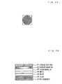
- FIG. 18 shows the printed output image 15 including the circular hairlines.
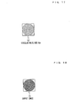
- FIG. 19 is an illustration showing an example printed image 1 of circular hairlines.
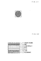
- FIG. 20 is an illustration showing the layer structure of the example printed image 1 of circular hairlines.
- FIG. 21 is an illustration showing an example printed image 2 of circular hairlines.
- FIG. 22 is an illustration showing the layer structure of the example printed image 2 of circular hairlines.
- FIG. 23 is an illustration showing an example printed image 3 of circular hairlines.
- FIG. 24 is an illustration showing the layer structure of the example printed image 3 of circular hairlines.
- FIG. 25 is an illustration showing an example printed image 4 of circular hairlines.
- FIG. 26 is an illustration showing the layer structure of the example printed image 4 of circular hairlines.
- the example printed image 1 of circular hairlines shown in FIG. 19 has a layer structure in which, after circular hairlines 61 are printed on an intermediate transfer film (not shown), a silver metallic layer 62, white layers 63 and 64 for increasing brightness, and a black layer 65 are printed thereon, and the circular hairlines 61 and the layers are transferred to a polycarbonate film 66.
- the example printed image 2 of circular hairlines shown in FIG. 21 has a layer structure in which, after smoke circular hairlines 71 are printed on an intermediate transfer film (not shown), a smoke layer 72 for suppressing glossiness, a silver metallic layer 73, white layers 74 and 75, and a black layer 76 are printed thereon, and the circular hairlines 71 and the layers are transferred to a polycarbonate film 77.
- the example printed image 3 of circular hairlines shown in FIG. 23 has a layer structure in which, in order to emphasize the 3D impression, black circular hairlines 81 are printed on a polycarbonate film 82, and a silver metallic layer 83, white layers 84 and 85, and a black layer 86 are printed thereon.
- the example printed image 4 of circular hairlines shown in FIG. 25 has a layer structure in which, after smoke circular hairlines 91 are printed on an intermediate transfer film (not shown), a circular gradation layer 92 of cyan, a silver metallic layer 93, white layers 94 and 95, and a black layer 96 are printed thereon, and the circular hairlines 91 and the layers are transferred to a polycarbonate film 97. Positioning of the circular hairlines 91 and the circular gradation layer 92 can be performed easily.
- a thermal recording apparatus or the like which reduces effects of heat accumulated in a thermal head and prints highly fine hairline images and circular hairlines by a low resolution.
- a horizontal hairline pattern is formed after the pattern definition; the shift processing is performed for the horizontal hairline pattern, whereby another horizontal hairline pattern is produced; the two horizontal hairline patterns are subjected to the polar coordinate conversion and the heat-accumulation correction processing; and two circular hairline images are printed in a superimposed state.
- the present embodiment may be modified such that the polar coordinate conversion and the heat-accumulation correction processing are performed for a single horizontal hairline pattern formed from the pattern definition, and circular hairlines are printed.
- circular hairlines having various widths can be readily printed by changing the numbers of black and white pixels used in the pattern definition.
- the structure and the processing details of the thermal printer 1 are generally the same as those in the first embodiment shown in FIGS. 1 and 2 .
- the flow of the image processing 23 of the second embodiment is partially changed to produce circular hairlines by performing polar coordinate conversion for a hairline image obtained from the input image 3 through CMYK/RGB-gray conversion, gradation conversion, and halftone conversion.
- FIG. 27 is a flowchart showing the flow of processing of the image processing 23 according to the third embodiment.
- the image input section 5 of the thermal printer reads the image data 3 (step 301); and the control section 9 holds an acquired image G 21 in the image memory 27 of the storage section 7 (step 302).
- control section 9 of the thermal printer 1 executes the image processing 23. That is, the control section 9 first converts the CMYK data or RGB data of the image G 21 to gray data in accordance with the resolution of the thermal printer 1 to thereby produce an image G 22 (step 303), and stores it in the image memory 27 of the storage section 7.
- the control section 9 of the thermal printer 1 performs the gradation conversion; i.e., converts the gradation of the image G 22 to thereby produce an image G 23 (step 304), and stores it in the image memory 27 of the storage section 7.
- control section 9 performs gradation conversion of about 65% when the resolution of the thermal printer 1 is 600 dpi (dots per inch). As shown in FIGS. 5, 6 , and 7 , an output image formed through the 65% gradation conversion provides hairlines thinner and finer than those provided by an output image formed through 100% gradation conversion and those provided by an output image formed through 80% gradation conversion.
- the control section 9 of the thermal printer 1 performs halftone processing for the image G 23 obtained through gradation conversion, to thereby produce an image G 24 (step 305).
- image data express the C, M, Y, K components with the same angle, for example, image data are of a line screen type (intersection angle: 90).
- the matrix size of each halftone dot varies depending on the resolution of the thermal printer 1 and the number of lines.
- the matrix size is 10 x 10 pixels for the case where the number of lines is 60 lpi (lines per inch), 8 x 8 pixels for the case where the number of lines is 75 lpi, 6 x 6 pixels for the case where the number of lines is 100 lpi, and 5 x 5 pixels for the case where the number of lines is 120 lpi.
- the control section 9 of the thermal printer 1 then performs polar coordinate conversion for the image G 24 obtained through the halftone processing, to thereby produce circular hairlines G 25 (step 306).
- control section 9 of the thermal printer 1 After the production of circular hairlines, the control section 9 of the thermal printer 1 performs heat-accumulation correction processing for the circular hairlines G 25 , to thereby produce circular hairlines G 26 (step 307).
- the control section 9 of the thermal printer 1 ends the step of the image processing 23 and sends the circular hairlines G 26 to the printing section 11 as final image data (step 308).
- the printing section 11 prints and outputs the circular hairlines G 26 as an output image 15 in accordance with an instruction from the control section 9 (step 309).
- polar coordinate conversion is performed for a hairline image obtained from the input image 3 through CMYK/RGB-gray conversion, gradation conversion, and halftone conversion, whereby fine circular hairlines are produced.
Landscapes
- Electronic Switches (AREA)
- Record Information Processing For Printing (AREA)
- Editing Of Facsimile Originals (AREA)
Applications Claiming Priority (3)
| Application Number | Priority Date | Filing Date | Title |
|---|---|---|---|
| JP2006096544A JP4358200B2 (ja) | 2006-03-31 | 2006-03-31 | 感熱記録装置、画像形成方法及び印画物 |
| JP2006096523A JP4358199B2 (ja) | 2006-03-31 | 2006-03-31 | 感熱記録装置、画像形成方法及び印画物 |
| EP07740040.6A EP2006114B1 (fr) | 2006-03-31 | 2007-03-28 | Dispositif d'enregistrement thermique, procédé de formation d'image et matière imprimée |
Related Parent Applications (2)
| Application Number | Title | Priority Date | Filing Date |
|---|---|---|---|
| EP07740040.6A Division-Into EP2006114B1 (fr) | 2006-03-31 | 2007-03-28 | Dispositif d'enregistrement thermique, procédé de formation d'image et matière imprimée |
| EP07740040.6 Division | 2007-03-28 |
Publications (2)
| Publication Number | Publication Date |
|---|---|
| EP2314455A1 true EP2314455A1 (fr) | 2011-04-27 |
| EP2314455B1 EP2314455B1 (fr) | 2012-05-23 |
Family
ID=38563416
Family Applications (2)
| Application Number | Title | Priority Date | Filing Date |
|---|---|---|---|
| EP07740040.6A Ceased EP2006114B1 (fr) | 2006-03-31 | 2007-03-28 | Dispositif d'enregistrement thermique, procédé de formation d'image et matière imprimée |
| EP10014987A Ceased EP2314455B1 (fr) | 2006-03-31 | 2007-03-28 | Imprimante thermique et procédé de formation d'images |
Family Applications Before (1)
| Application Number | Title | Priority Date | Filing Date |
|---|---|---|---|
| EP07740040.6A Ceased EP2006114B1 (fr) | 2006-03-31 | 2007-03-28 | Dispositif d'enregistrement thermique, procédé de formation d'image et matière imprimée |
Country Status (4)
| Country | Link |
|---|---|
| US (1) | US8031374B2 (fr) |
| EP (2) | EP2006114B1 (fr) |
| KR (1) | KR101351828B1 (fr) |
| WO (1) | WO2007114147A1 (fr) |
Cited By (1)
| Publication number | Priority date | Publication date | Assignee | Title |
|---|---|---|---|---|
| US9364995B2 (en) | 2013-03-15 | 2016-06-14 | Matterrise, Inc. | Three-dimensional printing and scanning system and method |
Citations (4)
| Publication number | Priority date | Publication date | Assignee | Title |
|---|---|---|---|---|
| EP0260917A2 (fr) * | 1986-09-19 | 1988-03-23 | Shinko Electric Co. Ltd. | Imprimante thermique par transfert |
| JPH06202445A (ja) | 1992-12-28 | 1994-07-22 | Canon Inc | 画像形成装置 |
| US20030053120A1 (en) * | 2001-08-28 | 2003-03-20 | Fuji Photo Film Co., Ltd. | Image transfer method, image server system, and program therefor |
| US20060033801A1 (en) * | 2004-08-14 | 2006-02-16 | Samsung Electronics Co., Ltd. | Method and apparatus for adjusting alignment of image forming device |
Family Cites Families (4)
| Publication number | Priority date | Publication date | Assignee | Title |
|---|---|---|---|---|
| JP2000135810A (ja) | 1998-08-26 | 2000-05-16 | Toppan Printing Co Ltd | 画像形成装置および画像形成方法並びに画像形成体 |
| JP4666432B2 (ja) | 2001-01-26 | 2011-04-06 | 大日本印刷株式会社 | ヘアラインパターンの作成装置 |
| JP4688121B2 (ja) * | 2001-04-04 | 2011-05-25 | 大日本印刷株式会社 | ヘアラインパターンの作成方法及び作成装置 |
| JP4386779B2 (ja) | 2004-03-31 | 2009-12-16 | 大日本印刷株式会社 | 蓄熱補正装置、蓄熱補正方法、及び感熱記録装置 |
-
2007
- 2007-03-28 WO PCT/JP2007/056602 patent/WO2007114147A1/fr not_active Ceased
- 2007-03-28 EP EP07740040.6A patent/EP2006114B1/fr not_active Ceased
- 2007-03-28 US US12/294,280 patent/US8031374B2/en not_active Expired - Fee Related
- 2007-03-28 EP EP10014987A patent/EP2314455B1/fr not_active Ceased
- 2007-03-28 KR KR1020087021170A patent/KR101351828B1/ko not_active Expired - Fee Related
Patent Citations (4)
| Publication number | Priority date | Publication date | Assignee | Title |
|---|---|---|---|---|
| EP0260917A2 (fr) * | 1986-09-19 | 1988-03-23 | Shinko Electric Co. Ltd. | Imprimante thermique par transfert |
| JPH06202445A (ja) | 1992-12-28 | 1994-07-22 | Canon Inc | 画像形成装置 |
| US20030053120A1 (en) * | 2001-08-28 | 2003-03-20 | Fuji Photo Film Co., Ltd. | Image transfer method, image server system, and program therefor |
| US20060033801A1 (en) * | 2004-08-14 | 2006-02-16 | Samsung Electronics Co., Ltd. | Method and apparatus for adjusting alignment of image forming device |
Cited By (1)
| Publication number | Priority date | Publication date | Assignee | Title |
|---|---|---|---|---|
| US9364995B2 (en) | 2013-03-15 | 2016-06-14 | Matterrise, Inc. | Three-dimensional printing and scanning system and method |
Also Published As
| Publication number | Publication date |
|---|---|
| EP2314455B1 (fr) | 2012-05-23 |
| EP2006114A2 (fr) | 2008-12-24 |
| EP2006114B1 (fr) | 2014-11-26 |
| EP2006114A4 (fr) | 2010-06-23 |
| KR20080105051A (ko) | 2008-12-03 |
| KR101351828B1 (ko) | 2014-01-23 |
| WO2007114147A1 (fr) | 2007-10-11 |
| EP2006114A9 (fr) | 2009-07-22 |
| US8031374B2 (en) | 2011-10-04 |
| US20090161166A1 (en) | 2009-06-25 |
Similar Documents
| Publication | Publication Date | Title |
|---|---|---|
| JP3109400B2 (ja) | ビット・マップ・データの処理方法 | |
| US8149462B2 (en) | Line printer | |
| EP2314455B1 (fr) | Imprimante thermique et procédé de formation d'images | |
| EP1734736A2 (fr) | Compensation pour les jets fonctionnant mal | |
| JP2006159505A (ja) | 画像形成方法およびその装置 | |
| US8164787B2 (en) | Thermal transfer recording device and image formation method | |
| JP2961503B2 (ja) | 中間調パターン生成方法 | |
| CN101410255B (zh) | 热敏记录装置、图像形成方法和印刷物 | |
| EP1946932B1 (fr) | Dispositif d impression thermique, procede de formation d image et objet imprime | |
| JP4929737B2 (ja) | 熱転写記録装置及び熱転写記録方法 | |
| JP4358200B2 (ja) | 感熱記録装置、画像形成方法及び印画物 | |
| JP3200519B2 (ja) | サーマルプリンタにおける画質改善方法 | |
| EP1865705A1 (fr) | Dispositif de generation de donnees d'image, programme de generation de donnees d'image, dispositif de transfert/d'enregistrement thermique et autres | |
| JP5100079B2 (ja) | ダイレクトマーキング印刷のための解像度因子の入れ替え | |
| JP3834573B2 (ja) | 建築板印刷装置 | |
| JP5360824B2 (ja) | 多階調の記録を行う方法および装置 | |
| JP2007313815A (ja) | 熱転写記録装置、画像形成方法及び印画物 | |
| JP2000000988A (ja) | 画像記録方法 | |
| JPH08290596A (ja) | フルカラー記録装置 | |
| JP2004064473A (ja) | 閾値マトリクスの作成方法およびカラー画像データの作成装置 | |
| JP2013131952A (ja) | 網点画像形成方法、熱転写装置 | |
| JPH10217528A (ja) | カラー画像記録方法、カラー画像記録装置、及びカラー画像記録制御方法 | |
| JP2006062084A (ja) | 感熱記録装置、プログラム、及び、記録媒体 | |
| JP2007268730A (ja) | 感熱記録装置、画像形成方法及び印画物 | |
| JPH0250872A (ja) | プリンタの印字方法 |
Legal Events
| Date | Code | Title | Description |
|---|---|---|---|
| PUAI | Public reference made under article 153(3) epc to a published international application that has entered the european phase |
Free format text: ORIGINAL CODE: 0009012 |
|
| AC | Divisional application: reference to earlier application |
Ref document number: 2006114 Country of ref document: EP Kind code of ref document: P |
|
| AK | Designated contracting states |
Kind code of ref document: A1 Designated state(s): DE FR GB IT |
|
| 17P | Request for examination filed |
Effective date: 20110817 |
|
| GRAP | Despatch of communication of intention to grant a patent |
Free format text: ORIGINAL CODE: EPIDOSNIGR1 |
|
| RIC1 | Information provided on ipc code assigned before grant |
Ipc: B41J 2/325 20060101ALI20110928BHEP Ipc: B41J 2/36 20060101ALI20110928BHEP Ipc: B41J 2/365 20060101AFI20110928BHEP |
|
| GRAS | Grant fee paid |
Free format text: ORIGINAL CODE: EPIDOSNIGR3 |
|
| GRAA | (expected) grant |
Free format text: ORIGINAL CODE: 0009210 |
|
| AC | Divisional application: reference to earlier application |
Ref document number: 2006114 Country of ref document: EP Kind code of ref document: P |
|
| AK | Designated contracting states |
Kind code of ref document: B1 Designated state(s): DE FR GB IT |
|
| REG | Reference to a national code |
Ref country code: GB Ref legal event code: FG4D |
|
| REG | Reference to a national code |
Ref country code: DE Ref legal event code: R096 Ref document number: 602007022915 Country of ref document: DE Effective date: 20120719 |
|
| PLBE | No opposition filed within time limit |
Free format text: ORIGINAL CODE: 0009261 |
|
| STAA | Information on the status of an ep patent application or granted ep patent |
Free format text: STATUS: NO OPPOSITION FILED WITHIN TIME LIMIT |
|
| 26N | No opposition filed |
Effective date: 20130226 |
|
| REG | Reference to a national code |
Ref country code: DE Ref legal event code: R097 Ref document number: 602007022915 Country of ref document: DE Effective date: 20130226 |
|
| REG | Reference to a national code |
Ref country code: FR Ref legal event code: PLFP Year of fee payment: 10 |
|
| REG | Reference to a national code |
Ref country code: FR Ref legal event code: PLFP Year of fee payment: 11 |
|
| REG | Reference to a national code |
Ref country code: FR Ref legal event code: PLFP Year of fee payment: 12 |
|
| PGFP | Annual fee paid to national office [announced via postgrant information from national office to epo] |
Ref country code: FR Payment date: 20190322 Year of fee payment: 13 Ref country code: GB Payment date: 20190320 Year of fee payment: 13 Ref country code: DE Payment date: 20190321 Year of fee payment: 13 Ref country code: IT Payment date: 20190325 Year of fee payment: 13 |
|
| REG | Reference to a national code |
Ref country code: DE Ref legal event code: R119 Ref document number: 602007022915 Country of ref document: DE |
|
| PG25 | Lapsed in a contracting state [announced via postgrant information from national office to epo] |
Ref country code: FR Free format text: LAPSE BECAUSE OF NON-PAYMENT OF DUE FEES Effective date: 20200331 Ref country code: DE Free format text: LAPSE BECAUSE OF NON-PAYMENT OF DUE FEES Effective date: 20201001 |
|
| GBPC | Gb: european patent ceased through non-payment of renewal fee |
Effective date: 20200328 |
|
| PG25 | Lapsed in a contracting state [announced via postgrant information from national office to epo] |
Ref country code: GB Free format text: LAPSE BECAUSE OF NON-PAYMENT OF DUE FEES Effective date: 20200328 |
|
| PG25 | Lapsed in a contracting state [announced via postgrant information from national office to epo] |
Ref country code: IT Free format text: LAPSE BECAUSE OF NON-PAYMENT OF DUE FEES Effective date: 20200328 |