EP2314852A1 - Kühlrippenstruktur für verbrennungsmotor eines fahrzeuges - Google Patents
Kühlrippenstruktur für verbrennungsmotor eines fahrzeuges Download PDFInfo
- Publication number
- EP2314852A1 EP2314852A1 EP09723689A EP09723689A EP2314852A1 EP 2314852 A1 EP2314852 A1 EP 2314852A1 EP 09723689 A EP09723689 A EP 09723689A EP 09723689 A EP09723689 A EP 09723689A EP 2314852 A1 EP2314852 A1 EP 2314852A1
- Authority
- EP
- European Patent Office
- Prior art keywords
- cooling fins
- cooling
- fin structure
- internal combustion
- combustion engine
- Prior art date
- Legal status (The legal status is an assumption and is not a legal conclusion. Google has not performed a legal analysis and makes no representation as to the accuracy of the status listed.)
- Withdrawn
Links
- 238000001816 cooling Methods 0.000 title claims abstract description 182
- 238000002485 combustion reaction Methods 0.000 title claims abstract description 37
- 230000003014 reinforcing effect Effects 0.000 claims abstract description 86
- 239000004576 sand Substances 0.000 abstract description 5
- 238000004140 cleaning Methods 0.000 abstract description 2
- 239000002245 particle Substances 0.000 description 7
- 239000000428 dust Substances 0.000 description 4
- 238000010276 construction Methods 0.000 description 3
- 239000000446 fuel Substances 0.000 description 3
- 239000006096 absorbing agent Substances 0.000 description 2
- 230000000694 effects Effects 0.000 description 2
- 230000035939 shock Effects 0.000 description 2
- XLYOFNOQVPJJNP-UHFFFAOYSA-N water Substances O XLYOFNOQVPJJNP-UHFFFAOYSA-N 0.000 description 2
- 230000002411 adverse Effects 0.000 description 1
- 230000000630 rising effect Effects 0.000 description 1
Images


Classifications
-
- F—MECHANICAL ENGINEERING; LIGHTING; HEATING; WEAPONS; BLASTING
- F02—COMBUSTION ENGINES; HOT-GAS OR COMBUSTION-PRODUCT ENGINE PLANTS
- F02F—CYLINDERS, PISTONS OR CASINGS, FOR COMBUSTION ENGINES; ARRANGEMENTS OF SEALINGS IN COMBUSTION ENGINES
- F02F1/00—Cylinders; Cylinder heads
- F02F1/02—Cylinders; Cylinder heads having cooling means
- F02F1/04—Cylinders; Cylinder heads having cooling means for air cooling
- F02F1/06—Shape or arrangement of cooling fins; Finned cylinders
- F02F1/065—Shape or arrangement of cooling fins; Finned cylinders with means for directing or distributing cooling medium
-
- F—MECHANICAL ENGINEERING; LIGHTING; HEATING; WEAPONS; BLASTING
- F01—MACHINES OR ENGINES IN GENERAL; ENGINE PLANTS IN GENERAL; STEAM ENGINES
- F01P—COOLING OF MACHINES OR ENGINES IN GENERAL; COOLING OF INTERNAL-COMBUSTION ENGINES
- F01P1/00—Air cooling
- F01P1/02—Arrangements for cooling cylinders or cylinder heads, e.g. ducting cooling-air from its pressure source to cylinders or along cylinders
- F01P2001/026—Cooling cylinder heads
-
- F—MECHANICAL ENGINEERING; LIGHTING; HEATING; WEAPONS; BLASTING
- F02—COMBUSTION ENGINES; HOT-GAS OR COMBUSTION-PRODUCT ENGINE PLANTS
- F02B—INTERNAL-COMBUSTION PISTON ENGINES; COMBUSTION ENGINES IN GENERAL
- F02B61/00—Adaptations of engines for driving vehicles or for driving propellers; Combinations of engines with gearing
- F02B61/02—Adaptations of engines for driving vehicles or for driving propellers; Combinations of engines with gearing for driving cycles
Definitions
- the present invention relates to a cooling fin structure for an internal combustion engine to be mounted on a vehicle, such as a motorcycle.
- the cylinder block and the cylinder head of an internal combustion engine to be mounted on a vehicle, such as a motorcycle, are provided on their surfaces with cooling fins for cooling the internal combustion engine by air currents. Since cooling fins are comparatively thin, adjacent cooling fins are connected by reinforcing ribs to enhance the rigidity of the cooling fins such that the fins are not caused to generate sounds by wind and vibrations and to increase heat radiating area by the reinforcing ribs. Such a cooling fin structure is described in Patent Document 1.
- An on-vehicle internal combustion engine provided with cooling fins connected by reinforcing ribs on its outer surface has an upper surface having recesses demarcated by the cooling fins and the reinforcing ribs and arranged in a grid.
- Sand and mud are liable to accumulate in the recesses to deteriorate engine cooling ability.
- An attempt to form part of each of the reinforcing ribs in a height lower by far than that of the cooling fins was made with an intention to lessen the adverse effect of such a problem to some extent.
- recesses remained without a change and hence the foregoing problem could not be completely solved.
- the present invention has been made to solve the above problem, and the object of the invention is to provide a cooling fin structure for an on-vehicle internal combustion engine in which sand and mud can hardly accumulate therein and which enables easy cleaning of the cooling fin structure and can prevent reduction of the cooling.
- the present invention provides a cooling fin structure for an on-vehicle internal combustion engine, comprising cooling fins formed in parallel arrangement on at least an upper surface of the on-vehicle internal combustion engine, wherein the cooling fins are each provided with reinforcing bulges on surfaces thereof: and the reinforcing bulges on each cooling fin are separated from adjacent cooling fins and from the reinforcing bulges on the adjacent cooling fins.
- the reinforcing bulges of adjacent ones of the parallel cooling fins are arranged alternately.
- the reinforcing bulges are formed such that the respective reinforcing bulges of the adjacent cooling fins do not overlap each other when viewed in a direction along the length of the cooling fins.
- the on-vehicle internal combustion engine has a forward-tilted or substantially horizontal cylinder, is suspended from a main frame extending obliquely downward to the rear from a head pipe included in a motorcycle and is provided with an air intake system for taking air into the engine, including parts disposed between the upper surface of a cylinder head and the main frame, and the cooling fins extends in a direction in which the motorcycle advances.
- the outermost one of the cooling fins is not provided with the reinforcing bulges on at least an outer surface thereof.
- the cooling fins in the present invention are provided on their surfaces with the reinforcing bulges. Therefore, the rigidity of the cooling fins is enhanced by the reinforcing bulges and hence the fins are prevented from generating sounds and noise (reduction of sounds and noise).
- the reinforcing bulges increase the surface areas of the cooling fins to improve cooling ability.
- the cooling fin structure of the present invention differs from the conventional cooling fin structure in that the reinforcing bulges on the cooling fins are separated from adjacent cooling fins and from the reinforcing bulges on the adjacent cooling fins. Therefore, the adjacent fins are not connected by the reinforcing bulges and hence the cooling fins and the reinforcing bulges do not form recesses.
- the reinforcing bulges are arranged such that the respective reinforcing bulges of the adjacent cooling fins do not coincide with each other with respect to a direction along the length of the cooling fins, cooling air can easily flow through spaces each formed between adjacent cooling fins, sand and mud are rarely stuck in the spaces each between the adjacent cooling fins and the spaces can be easily cleaned.
- the on-vehicle internal combustion engine is suspended from the main frame extending obliquely downward to the rear from the head pipe of the motorcycle and is provided with an air intake system for taking air into the engine, including parts disposed between the upper surface of a cylinder head and the main frame. Therefore, rainwater, which has adhered to the main frame and the parts of the air intake system while the vehicle is running, drips easily onto the cooling fin structure on the upper part of the internal combustion engine. Rainwater and such which have dripped onto the cooling fin structure can easily flow in the running direction of the vehicle and separate from the cooling fin structure because the cooling fins and the reinforcing bulges do not form divided recesses.
- the cooling fin structure is given an improved appearance.
- Fig. 1 shows a motorcycle provided with an internal combustion engine including a cooling fin structure in a preferred embodiment of the present invention.
- the motorcycle 1 has a body frame including, as principal components, a front fork 3 supporting a front wheel 2, a head pipe 4 connected to an upper part of the front fork 3, a main frame 5 extending obliquely downward to the rear from the head pipe 4, and a carrier frame 6 connected to the rear end of the main frame 5, curved in an upward convex shape and extending obliquely upward toward the rear, which are united in a unit to form the body frame.
- the upper part of the front fork 3 is rotatably supported in the head pipe 4.
- a transverse handlebar 7 is disposed above the head pipe 4.
- a seat 8 is disposed above the rear frame 6.
- Indicated at 9 is a body cover.
- the internal combustion engine 10 is disposed under the main frame 5 and is supported with its cylinder axis tilted forward so as to rise at a small inclination toward the front or with its axis extended substantially horizontally.
- the internal combustion engine 10 includes a crankcase 11, a cylinder block 12, a cylinder head 13 and a head cover 14.
- a chain case 15 extends rearward from the crankcase 11.
- a rear wheel 16 is supported on a rear end part of the chain case 15.
- the rear end of the chain case 15 is connected to the rear part of the rear frame 6 by a shock absorber 17.
- a leg shield 18 straddling the main frame 5 covers the cylinder block 12 and the cylinder head 13 of the internal combustion engine 10 from transverse directions.
- the rear frame 6 is covered with a rear cover 19.
- the seat 8 is placed on the rear cover 19.
- the internal combustion engine 10 is suspended from the main frame 5.
- the internal combustion engine 10 has a forward tilted or substantially horizontal cylinder, and an air intake system 20 is connected to an upper part of the cylinder head 13.
- the air intake system 20 includes an intake pipe 21, a throttle 22, an air cleaner 23 and so on. Intake air flows through the air cleaner 23, the air intake system 20 and the cylinder head 13 into the cylinder.
- An injector 24 injects fuel into the intake air.
- the air intake system 20 is disposed below the main frame 5; that is, the air intake system 20 is disposed in a space between the main frame 5 and the cylinder head 13.
- cooling fins 30 for air-cooling the internal combustion engine 10 are formed on the upper surface of cylinder block 12.
- the cooling fins 30 form a cooling fin structure 31 characterizing the present invention.
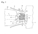
- Fig. 7 shows the intake pipe 25 of the air intake system 20.
- a fuel tube 26 for carrying fuel to the injector 24 is connected to a joint cap 27.
- indicated at 28 is a connector for the electrical equipment of the injector 24 and at 29 is a throttle body.
- the letter F indicates imaginary air flow in the body frame. As shown, the body cover 9 is open toward the front to facilitate taking in cooling air.
- Fig. 3 is a side elevation of the cylinder block 12 taken from the left side of the vehicle.
- the cooling fin structure 31 including the cooling fins 30 is formed on the upper surface of the cylinder block 12.
- the left side surface of the cylinder block 12 is not provided with any cooling fins.
- Indicated at 33 is a cylinder sleeve defining a cylinder bore.
- the cylinder sleeve 33 extends toward the rear.
- the cooling fins 30 of the cooling fin structure 31 are extended parallel to the running direction of the vehicle.
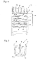
- the right side surface of the cylinder block 12 is provided with cooling fins 32 as shown in Fig. 4 .
- the cooling fins 32 will be described later.
- the number of the cooling fins 30 of the cooling fin structure 31 in this embodiment is, for example, six.
- the parallel cooling fins 30 extend in the running direction of the vehicle.
- Reinforcing ridges or bulges 34 are formed integrally with the cooling fins 30 on the surfaces of the cooling fins 30.
- Each reinforcing bulge 34 extends vertically along the height of the cooling fin 30.
- the surfaces of the reinforcing bulges 34 have the shape of a circular arc in cross section in a horizontal plane. Desirably, the reinforcing bulges 34 have a curved section gently rising from the flat surface of the cooling fins 30.
- the height of the reinforcing bulges 34 is far less than the distance between adjacent cooling fins 30. Therefore, even if the respective reinforcing bulges 34 of the adjacent cooling fins 30 are opposite to each other with respect to a direction perpendicular to the cooling fins 30, there is a gap between the opposite reinforcing bulges 34; that is, the reinforcing bulges 34 are formed such that the reinforcing bulges 34 of adjacent cooling fins 30 are separate from each other in a state where the respective reinforcing bulges 34 of adjacent cooling fins 30 are not opposite to each other with respect to a direction perpendicular to the cooling fins 30.
- the reinforcing bulges 34 of one of adjacent cooling fins 30 are not connected to parts of the surface not provided with the reinforcing bulges 34 of the other cooling fin 30.
- the length of the reinforcing bulges 34 is slightly smaller than the height of the cooling fins 30 on which the reinforcing bulges 34 are formed.
- Each reinforcing bulges 34 rises gradually in a gentle curve from a part of the cooling fin 30 slightly below the top edge of the cooling fin 30, extends downward linearly to a bottom wall 35 extending between adjacent cooling fins 30. It is important to determine dimensions such that the respective reinforcing bulges 34 of adjacent cooling fins 30 do not overlap each other as viewed in a direction parallel to the length of the cooling fins 30, namely, in a direction into the paper.
- the straight bottom wall 35 continuously extending in a direction parallel to the length of the cooling fins 30 is formed between adjacent cooling fins 30.
- the right end cooling fin 30 shown in the right half of Fig. 5 is not provided with the reinforcing bulges 34. Therefore, the right bottom wall 35 looks wider than the left bottom wall 35.
- the two reinforcing bulges 34 opposite to each other in Fig. 5 are not formed at the same position with respect to the length of the cooling fins 30. Therefore, the width of the left bottom wall 35 at each reinforcing bulge 34 is actually equal to that of the right bottom wall 35.
- the zigzag bottom walls 35 having parts of a minimum width corresponding to that width extend in the running direction of the vehicle.
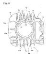
- Fig. 6 is an end view of the cylinder block 12 taken from the front side of the vehicle.
- the upper surface of the cylinder block 12 is provided with the cooling fin structure 31 including the cooling fins 30 and the reinforcing bulges 34 as shown in Fig. 6 .
- a space 39 in which a timing chain, not shown, is extended is shown on the right side in Fig. 6 , namely, the left side with respect to the running direction of the vehicle.
- the timing chain is extended between a drive sprocket, not shown, mounted on the crankshaft held in the crankcase 11 and a driven sprocket, not shown, mounted on a camshaft disposed in a valve train chamber to transmit the rotation of the crankshaft to the camshaft.
- the cooling fins 32 are shown in a left part in Fig. 6 . These cooling fins 32 include parallel vertical cooling fins 32a perpendicular to the axis of the cylinder and reinforcing ribs 32b parallel to the axis of the cylinder and connecting adjacent ones of the cooling fins 32a. The reinforcing ribs 32b have a height lower than that of the cooling fins 32a.
- the lower surface of the cylinder block 12 is provided with cooling fins 40a similar in construction to the cooling fins 32, and reinforcing ribs 40b perpendicular to the axis of the cylinder and connecting adjacent ones of the cooling fins 40a.
- the reinforcing ribs 40b have a height lower than that of the cooling fins 40a.
- Each reinforcing ribs 40b has an outward concave edge.
- the cooling fins 32 and 40 have cooling fin construction based on basically the same principle as that mentioned in Patent Document 1.
- the cooling fin structure in the preferred embodiment of the present invention for an on-vehicle internal combustion engine is formed in the foregoing construction.
- incoming air flows past the head cover 14, the cylinder head 13, the cylinder block 12 and the crankcase 11 to cool the internal combustion engine 10.
- the reinforcing bulges 34 are formed on the surfaces of the cooling fins 30 integrally therewith such that the respective reinforcing bulges 34 of the cooling fins 30 are not connected to the adjacent cooling fins 30 and to the reinforcing bulges 34 on the adjacent cooling fins 30. Therefore, the rigidity of the cooling fins 30 is enhanced by the reinforcing bulges 34 and the reinforcing bulges 34 increase the surface area of the cooling fin structure 31 to improve the cooling ability.
- the adjacent cooling fins 30, differing from the conventional cooling fins, are not connected by the reinforcing bulges 34, the cooling fins 30 and the reinforcing bulges 34 do not form divided recesses, and the continuous bottom walls 35 extending through the length of the cooling fins 30 are formed between adjacent ones of the cooling fins 30.
- grit and dust particles and mud that have entered the spaces between adjacent ones of the cooling fins 30 can hardly accumulate in those spaces and can be easily washed away with water even if grit and dust particles and mud accumulate in those space.
- the reinforcing bulges 34 having a gently curved section exert low resistance against the air flow.
- the respective reinforcing bulges 34 of the adjacent cooling fins 30 are arranged alternately and hence reduction of the sectional area of the air passages formed between the adjacent ones of the cooling fins 30 by the reinforcing bulges 34 can be limited to the least extent, and comparatively large grit particles and lumps of mud that have entered the spaces between the adjacent ones of the cooling fins 30 are rarely caught by the reinforcing bulges 34, can easily roll in the spaces and can easily go out of the spaces. Therefore, air passages each between the adjacent cooling fins can be easily cleaned. Air can easily flow through the air passages because the air passages are not narrowed.
- the internal combustion engine 10 is suspended from the main frame 5 extending obliquely downward to the rear from the head pipe 4 of the motorcycle and the air intake system 20 is disposed in the space between the main frame 5 and the cylinder head 13. Therefore, rainwater adhering to the main frame 5 and the air intake system 20 while the vehicle is running drips easily onto the cooling fin structure 31 on the upper part of the internal combustion engine 10. Rainwater and such which have dripped onto the cooling fin structure 31 can easily flow in the running direction of the vehicle and separate from the cooling fin structure 31 because the cooling fins 30 and the reinforcing bulges 34 do not form divided recesses but form the continuous bottom walls 35 extending in the running direction
- the left end cooling fin 30, namely, the outermost cooling fin 30 with respect to the width of the vehicle is provided with the reinforcing bulges 34 on its opposite surfaces as shown in Fig. 4 .
- the outermost cooling fin 30 may be not provided with any reinforcing bulges 34 at all or may be not provided with any reinforcing bulges 34 only on its outer surface with respect to the width of the vehicle; that is, at least the outer surface, with respect to the width of the vehicle, of the outermost cooling fin 30 may be not provided with the reinforcing bulges 34, which improves the appearance of the engine including the cooling fin structure 31.
- the cooling fin structure is formed only on the upper surface of the cylinder block.
- the cooling fin structure may be formed also on the upper surface of the cylinder head and when necessary, the cooling fin structure can be formed on surfaces other than the upper surfaces of the cylinder block and the cylinder head.
Landscapes
- Engineering & Computer Science (AREA)
- Chemical & Material Sciences (AREA)
- Combustion & Propulsion (AREA)
- Mechanical Engineering (AREA)
- General Engineering & Computer Science (AREA)
- Cylinder Crankcases Of Internal Combustion Engines (AREA)
Applications Claiming Priority (2)
| Application Number | Priority Date | Filing Date | Title |
|---|---|---|---|
| JP2008080119A JP5314909B2 (ja) | 2008-03-26 | 2008-03-26 | 車両搭載内燃機関 |
| PCT/JP2009/052985 WO2009119208A1 (ja) | 2008-03-26 | 2009-02-20 | 車両搭載内燃機関の冷却フィン構造 |
Publications (2)
| Publication Number | Publication Date |
|---|---|
| EP2314852A1 true EP2314852A1 (de) | 2011-04-27 |
| EP2314852A4 EP2314852A4 (de) | 2015-07-08 |
Family
ID=41113416
Family Applications (1)
| Application Number | Title | Priority Date | Filing Date |
|---|---|---|---|
| EP09723689.7A Withdrawn EP2314852A4 (de) | 2008-03-26 | 2009-02-20 | Kühlrippenstruktur für verbrennungsmotor eines fahrzeuges |
Country Status (7)
| Country | Link |
|---|---|
| EP (1) | EP2314852A4 (de) |
| JP (1) | JP5314909B2 (de) |
| CN (1) | CN101946078A (de) |
| AR (1) | AR070726A1 (de) |
| BR (1) | BRPI0909831B1 (de) |
| TW (1) | TWI360607B (de) |
| WO (1) | WO2009119208A1 (de) |
Cited By (1)
| Publication number | Priority date | Publication date | Assignee | Title |
|---|---|---|---|---|
| US11731502B2 (en) | 2021-03-31 | 2023-08-22 | Honda Motor Co., Ltd. | Internal combustion engine |
Families Citing this family (7)
| Publication number | Priority date | Publication date | Assignee | Title |
|---|---|---|---|---|
| JP5807446B2 (ja) * | 2011-08-25 | 2015-11-10 | スズキ株式会社 | エンジンの冷却構造 |
| WO2016063445A1 (ja) * | 2014-10-20 | 2016-04-28 | 本田技研工業株式会社 | シリンダブロック及びそれを備えたエンジン |
| CN106356624B (zh) * | 2016-11-02 | 2017-07-21 | 中信海洋(舟山)卫星通信有限公司 | 一种船载卫星天线的天线罩 |
| CN109826718A (zh) * | 2019-03-22 | 2019-05-31 | 无锡华源凯马发动机有限公司 | 大行程低排放单缸风冷柴油机的机体 |
| JP6892475B2 (ja) * | 2019-03-29 | 2021-06-23 | 本田技研工業株式会社 | 内燃機関 |
| CN113464261A (zh) * | 2021-08-23 | 2021-10-01 | 重庆龙力动力设备有限公司 | 一种通用垂直轴发动机的风冷组件 |
| WO2023188279A1 (ja) * | 2022-03-31 | 2023-10-05 | 本田技研工業株式会社 | 内燃機関の吸気構造 |
Family Cites Families (6)
| Publication number | Priority date | Publication date | Assignee | Title |
|---|---|---|---|---|
| JPS443685Y1 (de) * | 1966-02-08 | 1969-02-12 | ||
| JP3484501B2 (ja) * | 1996-03-05 | 2004-01-06 | ヤマハ発動機株式会社 | アンダーボーン型自動二輪車のエンジン冷却構造 |
| JP4256079B2 (ja) * | 2001-03-06 | 2009-04-22 | 本田技研工業株式会社 | 自動2輪車のエンジン冷却装置 |
| JP2003019992A (ja) * | 2001-07-09 | 2003-01-21 | Yamaha Motor Co Ltd | スクータ型自動二輪車の冷却装置 |
| JP3632848B2 (ja) * | 2001-10-31 | 2005-03-23 | 本田技研工業株式会社 | 自動二輪車用内燃機関 |
| JP4657937B2 (ja) * | 2006-01-31 | 2011-03-23 | 本田技研工業株式会社 | 車両用内燃機関 |
-
2008
- 2008-03-26 JP JP2008080119A patent/JP5314909B2/ja not_active Expired - Fee Related
-
2009
- 2009-02-20 BR BRPI0909831-3A patent/BRPI0909831B1/pt not_active IP Right Cessation
- 2009-02-20 WO PCT/JP2009/052985 patent/WO2009119208A1/ja not_active Ceased
- 2009-02-20 EP EP09723689.7A patent/EP2314852A4/de not_active Withdrawn
- 2009-02-20 CN CN2009801052369A patent/CN101946078A/zh active Pending
- 2009-02-26 TW TW098106197A patent/TWI360607B/zh not_active IP Right Cessation
- 2009-02-27 AR ARP090100721A patent/AR070726A1/es not_active Application Discontinuation
Non-Patent Citations (1)
| Title |
|---|
| See references of WO2009119208A1 * |
Cited By (1)
| Publication number | Priority date | Publication date | Assignee | Title |
|---|---|---|---|---|
| US11731502B2 (en) | 2021-03-31 | 2023-08-22 | Honda Motor Co., Ltd. | Internal combustion engine |
Also Published As
| Publication number | Publication date |
|---|---|
| TWI360607B (en) | 2012-03-21 |
| EP2314852A4 (de) | 2015-07-08 |
| BRPI0909831A2 (pt) | 2015-10-06 |
| JP5314909B2 (ja) | 2013-10-16 |
| CN101946078A (zh) | 2011-01-12 |
| TW200946767A (en) | 2009-11-16 |
| BRPI0909831B1 (pt) | 2019-12-17 |
| AR070726A1 (es) | 2010-04-28 |
| JP2009235930A (ja) | 2009-10-15 |
| WO2009119208A1 (ja) | 2009-10-01 |
Similar Documents
| Publication | Publication Date | Title |
|---|---|---|
| EP2314852A1 (de) | Kühlrippenstruktur für verbrennungsmotor eines fahrzeuges | |
| US7686116B2 (en) | Vehicle | |
| US8146693B2 (en) | Motorcycle and intake device thereof | |
| US9663175B2 (en) | Front fender structure for saddle-ride type vehicle | |
| CN100548783C (zh) | 跨骑式车辆 | |
| US9580142B2 (en) | Cooling structure for saddle-type vehicle | |
| US9067634B2 (en) | Motorcycle | |
| JP6196083B2 (ja) | 自動二輪車 | |
| EP2610155B1 (de) | Grätschsitz-Fahrzeug | |
| JP5144283B2 (ja) | 車両 | |
| CN101229831A (zh) | 跨骑式车辆 | |
| CN1194164C (zh) | 机动两轮车的发动机冷却装置 | |
| EP2949564B1 (de) | Fahrzeug | |
| JP5545937B2 (ja) | 自動二輪車 | |
| JP5772149B2 (ja) | 自動二輪車 | |
| JP7739961B2 (ja) | エアクリーナ | |
| JP5911094B2 (ja) | 鞍乗型車両 | |
| JP6003488B2 (ja) | 自動二輪車用吸気装置 | |
| US11840302B2 (en) | Air cleaner | |
| JP4317473B2 (ja) | 騎乗型車両用ラジエータ | |
| CN1185411C (zh) | 摩托车的内燃机 | |
| JPH0399992A (ja) | 自動2輪車のラジエタ装置 | |
| JP7440552B2 (ja) | シュラウド | |
| JP2015155653A (ja) | エンジンの冷却構造 | |
| JP2006233926A (ja) | エンジンの吸気系構造 |
Legal Events
| Date | Code | Title | Description |
|---|---|---|---|
| PUAI | Public reference made under article 153(3) epc to a published international application that has entered the european phase |
Free format text: ORIGINAL CODE: 0009012 |
|
| 17P | Request for examination filed |
Effective date: 20100927 |
|
| AK | Designated contracting states |
Kind code of ref document: A1 Designated state(s): AT BE BG CH CY CZ DE DK EE ES FI FR GB GR HR HU IE IS IT LI LT LU LV MC MK MT NL NO PL PT RO SE SI SK TR |
|
| AX | Request for extension of the european patent |
Extension state: AL BA RS |
|
| DAX | Request for extension of the european patent (deleted) | ||
| RA4 | Supplementary search report drawn up and despatched (corrected) |
Effective date: 20150605 |
|
| RIC1 | Information provided on ipc code assigned before grant |
Ipc: F01P 1/02 20060101ALI20150529BHEP Ipc: F02F 1/06 20060101AFI20150529BHEP |
|
| STAA | Information on the status of an ep patent application or granted ep patent |
Free format text: STATUS: THE APPLICATION IS DEEMED TO BE WITHDRAWN |
|
| 18D | Application deemed to be withdrawn |
Effective date: 20160105 |