EP2315022B1 - Colonne de chromatographie - Google Patents
Colonne de chromatographie Download PDFInfo
- Publication number
- EP2315022B1 EP2315022B1 EP09013435A EP09013435A EP2315022B1 EP 2315022 B1 EP2315022 B1 EP 2315022B1 EP 09013435 A EP09013435 A EP 09013435A EP 09013435 A EP09013435 A EP 09013435A EP 2315022 B1 EP2315022 B1 EP 2315022B1
- Authority
- EP
- European Patent Office
- Prior art keywords
- frit
- chamber
- annular protrusion
- ring
- tube
- Prior art date
- Legal status (The legal status is an assumption and is not a legal conclusion. Google has not performed a legal analysis and makes no representation as to the accuracy of the status listed.)
- Active
Links
Images


Classifications
-
- G—PHYSICS
- G01—MEASURING; TESTING
- G01N—INVESTIGATING OR ANALYSING MATERIALS BY DETERMINING THEIR CHEMICAL OR PHYSICAL PROPERTIES
- G01N30/00—Investigating or analysing materials by separation into components using adsorption, absorption or similar phenomena or using ion-exchange, e.g. chromatography or field flow fractionation
- G01N30/02—Column chromatography
- G01N30/60—Construction of the column
- G01N30/6004—Construction of the column end pieces
- G01N30/6026—Fluid seals
-
- G—PHYSICS
- G01—MEASURING; TESTING
- G01N—INVESTIGATING OR ANALYSING MATERIALS BY DETERMINING THEIR CHEMICAL OR PHYSICAL PROPERTIES
- G01N30/00—Investigating or analysing materials by separation into components using adsorption, absorption or similar phenomena or using ion-exchange, e.g. chromatography or field flow fractionation
- G01N30/02—Column chromatography
- G01N30/60—Construction of the column
- G01N30/6004—Construction of the column end pieces
- G01N30/603—Construction of the column end pieces retaining the stationary phase, e.g. Frits
-
- G—PHYSICS
- G01—MEASURING; TESTING
- G01N—INVESTIGATING OR ANALYSING MATERIALS BY DETERMINING THEIR CHEMICAL OR PHYSICAL PROPERTIES
- G01N30/00—Investigating or analysing materials by separation into components using adsorption, absorption or similar phenomena or using ion-exchange, e.g. chromatography or field flow fractionation
- G01N30/02—Column chromatography
- G01N30/50—Conditioning of the sorbent material or stationary liquid
- G01N30/52—Physical parameters
- G01N2030/522—Physical parameters pressure
-
- G—PHYSICS
- G01—MEASURING; TESTING
- G01N—INVESTIGATING OR ANALYSING MATERIALS BY DETERMINING THEIR CHEMICAL OR PHYSICAL PROPERTIES
- G01N30/00—Investigating or analysing materials by separation into components using adsorption, absorption or similar phenomena or using ion-exchange, e.g. chromatography or field flow fractionation
- G01N30/02—Column chromatography
- G01N30/60—Construction of the column
- G01N30/6052—Construction of the column body
- G01N30/6065—Construction of the column body with varying cross section
-
- Y—GENERAL TAGGING OF NEW TECHNOLOGICAL DEVELOPMENTS; GENERAL TAGGING OF CROSS-SECTIONAL TECHNOLOGIES SPANNING OVER SEVERAL SECTIONS OF THE IPC; TECHNICAL SUBJECTS COVERED BY FORMER USPC CROSS-REFERENCE ART COLLECTIONS [XRACs] AND DIGESTS
- Y10—TECHNICAL SUBJECTS COVERED BY FORMER USPC
- Y10T—TECHNICAL SUBJECTS COVERED BY FORMER US CLASSIFICATION
- Y10T29/00—Metal working
- Y10T29/49—Method of mechanical manufacture
- Y10T29/49826—Assembling or joining
Definitions
- the present invention relates generally to the design, assembly and use of columns utilized for analytical separation in the field of liquid chromatography.
- LC Liquid chromatography
- a mobile phase or solvent
- the mobile phase is forced through a stationary phase that is immiscible relative to the mobile phase.
- the stationary phase is provided in the form of a volume of particles (a column packing bed) supported in a column or cartridge through which the sample and mobile phase flow.
- the column packing bed is typically retained at each end of the column by a frit or filter that allows the mobile phase and sample to flow through while preventing the packing material from escaping the column.
- the frits are typically secured in place by end fittings located at the column inlet end and outlet end, respectively.
- the inlet end of the column is connected to an inlet conduit by which the sample/mobile phase is introduced into the column.
- a mobile phase reservoir, pump and sample injector are located upstream and interconnected to the column inlet via the inlet conduit.
- the outlet end of the column is connected via an outlet conduit to a suitable detector, which may operate based on ultraviolet or visible light absorbance, conductivity, fluorescence, light scattering, mass resolution, etc.
- the respective compositions of the mobile phase and stationary phase are selected to cause the analytes of the sample to become distributed between the mobile phase and stationary phase to varying degrees dependent on the nature of the respective analytes.
- Analytes that are strongly retained by the stationary phase travel slowly with the mobile phase, while analytes that are weakly retained by the stationary phase travel more rapidly.
- analytes of differing compositions become separated from each other as the mobile phase flows through the column.
- the analytes are in effect sorted sequentially as the eluent flows out from the column, thereby facilitating their analysis by the detector.
- the mechanical separation power or efficiency of a chromatography column depends in part on the physical attributes of the packing bed (stationary phase). To realize acceptable efficiency and resolution, the packing bed must be stable and uniformly packed. Dead spaces or voids within the packing material, or more generally reduced particle density, result in peak broadening and/or peak tailing observed in the acquired data and consequently loss of potentially valuable analytical information. Loss of stability or uniformity in the packing material may be caused by a number of factors, such as a poorly designed column packing process, a subsequent column assembly step that allows the density of the packing bed to be reduced, or subsequent use of the column in which the high-pressure fluid flow required for the LC technique destabilizes the packing bed.
- an LC column in which a preformed filter assembly at the inlet end has a filter that includes a protruding portion. When the filter assembly is installed, the filter protrudes into the interior of the column where the packing bed is located to attain some compression of the packing bed.
- a metal filter is press-fitted into the open end of the column tube. Upon installation of an end fitting of the column, a metal compression body bears against the end of the tube of the column, which deforms the end of the tube. As the end of the tube yields in this manner, the compression body contacts the filter and causes the filter to bear against the packing bed to attain compression thereof.
- a chromatography column includes a tube, a frit assembly, a first end fitting and a second end fitting.
- the tube includes an annular first end face circumscribing a first tube opening, an annular second end face circumscribing a second tube opening, an axial bore in fluid communication with the first tube opening and the second tube opening, and an annular protrusion extending axially from the first end face to an axial protrusion height and having an inner diameter greater than an inner diameter of the axial bore.
- the annular protrusion circumscribes a chamber in fluid communication with the axial bore at the first tube opening.
- the frit assembly includes a first frit and a ring surrounding the first frit, wherein the frit assembly has a frit opening having an inner diameter less than the inner diameter of the annular protrusion.
- the ring has an outer diameter greater than an outer diameter of the annular protrusion, and a yield strength less than a yield strength of the annular protrusion, the ring contacting the annular protrusion.
- the first frit and a portion of the ring less than the inner diameter of the chamber cooperatively define a chamber boundary axially opposite to the first end face.
- the chamber has an axial chamber height extending from the first end face to the chamber boundary.
- the first end fitting is securely fastened to the tube and includes a frit retaining surface contacting the ring, wherein the ring is axially compressed between the frit retaining surface and the annular protrusion, the ring is deformed around the annular protrusion, and the chamber height is reduced to less than the protrusion height.
- a second frit may be disposed in fluid communication with the second tube opening.
- the second end fitting, in which the second frit is disposed, may be securely fastened to the tube.
- a method for assembling a chromatography column.
- a tube of the chromatography column is filled with a particulate packing material via a first opening of the column while preventing the particulate packing material from escaping through an axially opposite second opening of the column.
- the tube has an axial bore extending between a first end face and a second end face of the tube, and a chamber circumscribed by an annular protrusion extending axially from the first end face to an axial protrusion height.
- the annular protrusion has an inner diameter greater than an inner diameter of the axial bore. Both the axial bore and the chamber are filled.
- a ring of a frit assembly is placed into contact with the annular protrusion wherein the chamber has an axial chamber height initially equal to the protrusion height.
- the ring has an outer diameter greater than an outer diameter of the annular protrusion, and surrounds a first frit of the frit assembly wherein the frit assembly has a frit opening having an inner diameter less than the inner diameter of the annular protrusion.
- the packing material is compressed by axially moving a first end fitting into contact with the frit assembly and into secure engagement with the tube, wherein the ring becomes axially compressed between the frit retaining surface and the annular protrusion, and the ring deforms around the annular protrusion such that the annular protrusion extends into a thickness of the ring, and the chamber height is reduced to less than the protrusion height.
- a second frit may be installed at the second opening.
- a second end fitting may be secured to the tube opposite to the first end fitting.
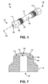
- Figure 1 is a perspective view of an example of a chromatography column according to an implementation of the present disclosure.
- Figure 2 is a cross-sectional view of the column illustrated in figure 1 along a longitudinal axis thereof.
- Figure 3 is a lengthwise view along the longitudinal axis of a tube that may be provided with the column illustrated in figures 1 and 2 .
- Figure 4 is a cross-sectional view of the tube illustrated in figure 3 along the longitudinal axis.
- Figure 5 is a cross-sectional view of an end portion that may be provided with the column illustrated in figures 1 and 2 .
- Figure 6 is a cross-sectional view of a frit retainer that may be provided with the column illustrated in figures 1 and 2 .
- Figure 7 is a perspective view in cross-section of one axial end of the tube illustrated in figures 3 and 4 .
- Figure 8 is a side view of an example of a frit assembly that may be provided with the column illustrated in figures 1 and 2 .
- Figure 9 is a plan view of the frit assembly illustrated in figure 8 .
- Figure 10 is a cross-sectional view along the longitudinal axis of an end section of the column illustrated in figures 1 and 2 , wherein the column is unassembled.
- Figure 11 is a cross-sectional view along the longitudinal axis of column end section illustrated in figure 10 , wherein the column is assembled.
- Figure 1 is a perspective view of an example of a chromatography column 100 according to an implementation of the present disclosure.
- the column 100 generally extends along a longitudinal axis 102 from a first axial end 104 to a second axial end 106 .
- the features of the column 100 may be the same at the first end 104 and the second end 106 , in which case the designation of which column end 104 or 106 serves as the inlet end or the outlet end is arbitrary.
- the column 100 generally includes a tube 110 elongated along the axis 102 , a first end fitting 114 securely engaging the tube 110 at the first end 104 , and a second end fitting 118 securely engaging the tube 110 at the second end 106 .
- securely engaging generally means that after the column 100 has been assembled as shown in figure 1 , the end fittings 114 , 118 will not become disengaged from the tube 110 during normal, intended operations of the column 100 , including at the pressures typically contemplated for the specific type of chromatography being performed (e.g., HPLC, U(H)PLC, etc.).
- the end fittings 114 , 118 may be securely engaged to the tube 110 via the mating of complementary threads (not shown) on inside surfaces of the end fittings 114 , 118 and outside surfaces of the tube 110 .
- the end fittings 114 , 118 may include flats 122 for manipulation by a tool and/or knurling 124 , and the tube 110 may likewise include flats 126 .
- the end fittings 114 , 118 may be securely engaged to the tube 110 by press-fitting, welding, brazing, etc.
- Each end fitting 114 , 118 includes a bore 128 adapted for connection to the fluid lines of a chromatographic system.
- the bore 128 may include threads for engaging a fluid conduit fitting (not shown).
- Each borne 128 is in fluid communication with an axial bore of the tube 110 , whereby a fluid flow path is established from the first (inlet) end 104 , through the tube 110 and to the second (outlet) end 106 in a manner appreciated by persons skilled in the art.
- Figure 2 is a cross-sectional view of the column 100 along the longitudinal axis 102 .
- the tube 110 includes an axial bore 210 extending from one axial end of the tube 110 to the opposite axial end of the tube 110 .
- the axial bore 210 contains (is filled with) a particulate packing material providing the stationary phase for chromatography.
- Respective frit (or filter) assemblies 214 , 218 are positioned at each axial end of the tube 110 .
- the frit assemblies 214 , 218 provide axial boundaries holding the particulate packing material in place, yet include central porous sections to enable passage of the mobile phase/sample matrix as appreciated by persons skilled in the art.
- respective threads of the end fittings 114 , 118 and the tube 110 form annular threaded areas 222 , 224 near the respective axial ends of the tube 110 .
- the first end fitting 114 includes an end portion 228 and a frit retainer 232 .
- the end portion 228 and the frit retainer 232 may be physically separate components as in the present example, or alternatively may be integrated as a single-piece construction for the first end fitting 114 .
- the end portion 228 may include a sleeve 236 that coaxially surrounds a portion of the tube 110 .
- the threads of the end fitting associated with the threaded area 222 may be formed on an inside surface of the sleeve 236 .
- the frit retainer 232 is positioned in abutment with the frit assembly 214 in opposition to the axial end of the tube 110 .
- the frit retainer 232 may include a sleeve 240 that coaxially surrounds the axial end of the tube 110 .
- the frit retainer 232 includes a through-bore 244 in fluid communication with the axial bore 210 via the frit assembly 232 , thereby fluidly interconnecting the axial bore 210 of the tube 110 and the bore 128 of the end fitting 114 .
- the end portion 228 may coaxially surround the frit retainer 232 , with an inside surface of the end portion 228 abutting the frit retainer 232 in opposition to the frit assembly 214 .
- the fluid path through the assembled column 100 runs through the bore 128 of the end portion 228 (or through a fluid conduit or fitting connected to the bore 128 ), the bore 244 of the frit retainer 232 , a porous central portion of the first frit assembly 214 , the axial bore 210 , the second frit assembly 218 , and a bore 248 of the second end fitting 118 .
- axial movement of the end fitting 114 relative to the tube 110 in the direction of the opposing end causes at least a portion of the frit assembly 214 to become axially compressed between the frit retainer 232 and the axial end of the tube 110 in a manner described further below.
- axial movement of the end fitting 114 entails mating the threads at the threaded area 222 and rotating the end portion 228 relative to the tube 110 .
- the second frit assembly 218 may be of similar configuration to the first frit assembly 214 , and the second end fitting 118 may include a second end portion 252 with a bore 248 and a sleeve 262 and a second frit retainer 256 with a bore 264 and a sleeve 268 .
- the second frit assembly 218 may be axially compressed after axial movement of the second end fitting 118 relative to the tube 110 .
- the fluid path thus runs from the axial bore 210 through a porous central portion of the second frit assembly 218 , the bore 264 of the second frit retainer 256 , and the bore 248 of the second end portion 252 .
- Figure 3 is a lengthwise view of the tube 110 along the longitudinal axis 102
- figure 4 is a cross-sectional view of the tube 110 along this axis 102
- the tube 110 includes a first axial end face 304 and an opposing second axial end face 308 .
- the tube 110 further includes an annular protrusion 312 that extends from the first end face 304 in the axial direction away from the axial bore 210 .
- the tube 110 also includes a second annular protrusion 316 that extends from the second end face 308 in the axial direction away from the axial bore 210 .
- the tube 110 has an outer surface 402 and an inner surface 404 .
- portions of the outer surface 402 include threads (not shown) that mate with threads of the end fittings 114 , 118 ( figure 2 ).
- the inner surface 404 circumscribes (defines) the axial bore 210 .
- the axial bore 210 extends between a first opening 412 and a second opening 416 of the tube 110 .
- the first annular protrusion 312 is located at and coaxial with the first tube opening 412
- the second annular protrusion 316 is located at and coaxial with the second tube opening 416 .
- the tube 110 may have any size suitable for the chromatographic application for which the column 100 is intended.
- the outer diameter of the tube 110 may range from 0.1 mm to 30 mm
- the inner diameter of the tube 110 (the diameter of the axial bore 210 ) may range from 0.05 mm to 29 mm.
- Figure 5 is a cross-sectional view of an end portion 528 , which may correspond to the first end portion 228 or the second end portion 252 shown in figure 2 , or both:
- the bore 128 of the end portion 528 opens into a larger-diameter cavity 562 circumscribed by an inside lateral surface 566 of the sleeve portion 236 .
- the inside diameter of the sleeve portion 236 is larger than the outside diameter of the portion of the tube 110 over which the sleeve portion 236 fits.
- the bore 128 of the end portion 528 opens at the cavity 562 at an inside axial surface 570 .
- a section of an inside lateral surface 566 of the sleeve portion 236 is threaded (not shown) to engage corresponding threads on the outside surface of the tube 110 .
- the sleeve portion 236 encloses the frit retainer 232 and the frit assembly 214 , i.e., the frit retainer 232 and the frit assembly 214 are disposed in the cavity 562 of the end portion 528 .
- Figure 6 is a cross-sectional view of a frit retainer 632 , which may correspond to the first frit retainer 232 or the second frit retainer 256 shown in figure 2 , or both.
- the bore 244 of the frit retainer 632 may have one or more sections of different diameter, such as tapered sections and/or sections creating step-wise changes in area, as necessary for providing leak-free fluid connections at the end fitting.
- the frit retainer 632 includes a sleeve portion 640 circumscribing a cavity 662 .
- the inside diameter of the sleeve portion 640 is larger than the outside diameter of the portion of the tube 110 over which the sleeve portion 640 fits.
- the bore 244 of the frit retainer 632 opens at the cavity 662 at a frit retaining surface 670 .
- the inside axial surface 570 of the end portion 528 ( figure 5 ) bears against an axial surface 674 of the frit retainer 632 opposite to the frit retaining surface 670 and, in turn, the frit retaining surface 670 bears against the frit assembly 214 ( figure 2 ) on a side of the frit assembly 214 opposite to the annular protrusion 312 ( figure 3 ).
- Figure 7 is a perspective view in axial cross-section of one axial end of the tube 110 .
- the illustrated end may be the inlet end or the outlet end of the tube 110 , or may be representative of both ends.
- Figure 7 illustrates more clearly the annular protrusion 712 that extends from the axial end face of the tube 110 at the tube opening 412 .
- the inside diameter of the annular protrusion 712 is greater than the inside diameter of the axial bore 210 , and the outside diameter of the annular protrusion 712 is less than the outside diameter of the outer surface of the tube 110 at this location.
- the annular protrusion 712 partitions the axial end face into an inner end face portion 704 circumscribing the tube opening 412 and an outer end face portion 708 coaxial with the inner end face portion 704 .
- the annular protrusion 712 circumscribes a chamber 710 positioned in fluid communication with the axial bore 210 via the tube opening 412 . It can be seen that the chamber 710 is bounded at one axial end by the inner end face portion 704 , at the opposing axial end by the frit assembly 214 ( figure 2 ), and in the radial direction by the inner surface (inside diameter) of the annular protrusion 712 .
- both the chamber 710 and the axial bore 210 are filled with the particulate packing material.
- the annular protrusion 712 extends from the axial end face 704 , 708 to a fixed axial protrusion height defined between the axial end face 704 , 708 and an opposing axial end surface 716 of the annular protrusion 712 (or to a point or apex of the annular protrusion 712 , depending on its shape). It thus can be seen that when the frit assembly 214 is placed in contact with the annular protrusion 712 (i.e., into abutment with its axial end surface 716 ), the portion of the frit assembly 214 coextensive with the inside diameter of the annular protrusion 712 serves as an upper chamber boundary, the term "upper" being descriptive solely from the perspective of figure 7 .
- the axial height of the chamber 710 is equal to the protrusion height.
- the term “equal” is intended to encompass the term “substantially equal” to take into account an implementation in which the surface of the frit assembly 214 bounding the chamber 710 may not be perfectly flat or planar.
- the axial compressive forces imparted during assembly of the column 100 cause a portion of the frit assembly 214 to become deformed around the annular protrusion 712 . From the perspective of figure 7 , this compression has the effect of "lowering" the upper chamber boundary presented by the frit assembly 214 toward the tube opening 412 . Stated differently, after compression the axial chamber height is reduced to a value less than the fixed protrusion height.
- the chamber boundary may be characterized as being axially movable (or variable, or adjustable) from a first position at which the chamber height is at a maximum or initial value (equal to the protrusion height) to a second or final position at which the chamber height is a reduced chamber height.
- the chamber volume defined by the variable chamber height and the fixed inside diameter of the annular protrusion 712 , is also reduced from a maximum value at the first position to a reduced value at the second position.
- the chamber 710 provides an additional space into which particulate packing material is filled during assembly.
- the axial movement of the movable chamber boundary in consequence of the axial movement of the end fitting 114 into secure engagement with the tube 110 ) compresses the particulate packing material residing in the chamber 710 , whereby at least some of the packing material in the chamber 710 is forced into the axial bore 210 . This ensures that the packing material provided with the finally assembled column 100 is at a density and stability desired for that particular column 100 .
- the annular protrusion 712 may be shaped or profiled in a manner that promotes deformation of the frit assembly 214 .
- the annular protrusion 712 includes chamfered edges.
- the annular protrusion 712 may have a rounded or domed profile.
- the annular protrusion 712 may be shaped so as to facilitate extension or excursion of the annular protrusion 712 into the thickness of the deformable portion of the frit assembly 214 .
- FIG 8 is a side view of an example of a frit (or filter) assembly 814 , which may correspond to the first frit assembly 214 or the second frit assembly 218 shown in figure 2 , or both.
- Figure 9 is a plan view of the same frit assembly 814 .
- the frit assembly 814 generally includes a first axial surface 822 and an opposing second axial surface 824 .
- the frit assembly 814 is axially interposed between the frit retainer 232 and corresponding axial end of the tube 110 ( figure 2 ).
- the first axial surface 822 may contact the frit retaining surface 670 ( figure 6 ) and the second axial surface 824 may contact the annular protrusion 712 ( figure 7 ).
- the frit assembly 814 includes a frit 932 encapsulated or surrounded by a deformable material.
- the frit assembly 814 is fabricated such that the deformable material has the form of a ring 934 that circumscribes a central frit opening 936 through which the frit 932 spans.
- each axial surface 822 , 824 lies entirely in the same plane such that the axial thickness of the frit assembly 814 is uniform along any radial direction, this is not a limitation of the frit assemblies encompassed by the present disclosure.
- the axial thickness of the frit 932 may be greater or less than the axial thickness of the ring 934 that encloses the frit 932 .
- the frit 932 may be composed of any mesh or porous material suitable for use in chromatographic columns. The mesh size or porosity of the frit 932 is sufficient to retain the particulate packing material in the tube 110 .
- the frit material include, but are not limited to, various metals and metal alloys such as sintered steel, stainless steel, etc., ceramics such as titanium dioxide, polymers such as PEEK (polyaryletheretherketone), etc.
- the ring 934 may be composed of any suitable deformable material.
- a "deformable material” is one that enables the ring 934 to deform around the annular protrusion 712 during assembly of the column 100 , to a degree sufficient to reduce the chamber height and compress the packing bed in accordance with the teachings disclosed herein.
- the "deformable material" of the ring 934 may be characterized as being weak in comparison to the material of the annular protrusion 712 ---that is, the ring 934 is composed of a weak material while the annular protrusion 712 is composed of a hard material.
- a "weak” material may be characterized as one having a yield strength (or tensile strength) less than 200 MPa, while a "hard” material may be characterized as one having a yield strength of 200 MPa or greater.
- the ring 934 may be composed of a material having a yield strength less than 200 MPa and the annular protrusion 712 may be composed of a material having a yield strength of 200 MPa or greater.
- the ring material include, but are not limited to, PEEK, Teflon® (polytetrafluoroethylene), etc.
- the yield strength of a PEEK ring 934 may range from about 89.6-140 MPa.
- Non-limiting examples of the material of the annular protrusion 712 include, but are not limited to, various metals and metal alloys such as titanium, stainless steel, etc., various glasses, and various hard polymers (i.e., polymers having a yield strength of 200 MPa or greater).
- the ring 934 has a yield strength ranging from 40 to 199 MPa and the annular protrusion 712 has a yield strength ranging from 400 to 2000 MPa.
- the diameter of the central frit opening 936 (the inside diameter of the ring 934 ) is less than the inside diameter of the annular protrusion 712 ( figure 7 ), while the outside diameter of the ring 934 is greater than the outside diameter of the annular protrusion 712 .
- the ring 934 may have an inside diameter of about 2.4 mm, an outside diameter of about 5.45 mm, and a thickness of about 0.8 mm.
- the frit assembly 814 is centered on the annular protrusion 712 such that central frit opening 936 is aligned with the chamber 710 and the tube opening 412 along the central axis of the tube 110 while the deformable ring 934 is brought into contact with the axial surface 716 of the annular protrusion 712 .
- the solid, deformable portion of the ring 934 may be characterized as having a lateral width (in the horizontal direction from the perspective of figures 8 and 9 ) defined as the difference in the radii of the outer sidewall and inner sidewall of the ring 934 (or the difference in the outer and inner diameters of the ring 934 , divided by 2).
- the annular protrusion 712 may likewise be characterized as having a lateral width defined as the difference in the radii of the outer sidewall and inner sidewall of the annular protrusion 712 .
- the lateral width of the ring 934 is greater than the lateral width of the annular protrusion 712 .
- the lateral width of the ring 934 is large enough to ensure that a sufficient amount of the ring material deforms around the outer surfaces of the annular protrusion 712 , to result in a sufficient reduction in chamber height and consequent compression of the packing bed.
- the ring material is deformed to a degree that the ring is in compressive contact with the axial end face 704 , 708 of the tube 110 or at least with the outer section 708 thereof ( figure 7 ).
- Figure 10 is a cross-sectional view along the longitudinal axis of an end section of the column 100 in unassembled form, but after the axial bore 210 and the chamber 710 have been filled with a packing material 1002 (only partially shown for simplicity) and the frit assembly 814 has been placed in contact with the annular protrusion 712 provided at this end of the tube 110 .
- the arrangement of the column 100 illustrated in figure 10 will be referred to as the first position of the column 100 .
- the chamber 710 is in open communication with the axial bore 210 of the tube 110 .
- the chamber 710 is bounded in the radial direction by the inner wall of the annular protrusion 712 corresponding to its inside diameter, and in the axial direction by the inner section 704 of the axial end face of the tube 110 within the inside diameter of the annular protrusion 712 and by the axially opposing chamber boundary.
- the chamber boundary is defined by that portion of the side the frit assembly 814 facing the chamber 710 and within the inside diameter of the annular protrusion 712 .
- the chamber boundary includes the frit 932 and the portion of the deformable ring 934 within the inside diameter of the annular protrusion 712 .
- the axial height of the chamber 710 is at a maximum chamber height 1006 .
- figure 11 is a cross-sectional view of the same column end section but after the column 100 has been assembled.
- the finally assembled form of the column 100 illustrated in figure 11 will be referred to as the second position of the column 100 .
- the end fitting includes the end portion 228 and frit retainer 232 described earlier in this disclosure, and secure engagement/assembly is as follows.
- the frit retainer 232 is positioned onto the frit assembly 814 and the end portion 228 is positioned onto the frit retainer 232 in the manner described earlier.
- the positioning of the end portion 228 entails mating threads of the end portion 228 with threads of the tube 110 at a threaded area 222 of a desired axial length.
- the end portion 228 is then moved or translated in the axial direction toward the tube 110 (downward from the perspective of figure 11 ), which in the present example entails screwing the end portion 228 onto the tube 110 via the threaded engagement along the threaded area 222 .
- the axial movement of the end portion 228 relative to tube 110 causes the end portion 228 to bear against the frit retainer 232 and, in turn, the frit retainer 232 to bear against the frit assembly 814 . Consequently, the frit assembly 814 becomes axially compressed between the frit retainer 232 and the annular protrusion 712 .
- the ring 934 of the frit assembly 814 is deformable and significantly weaker (more yielding) than the annular protrusion 712 , the ring 934 becomes deformed around the axial surface 716 and inner and outer sidewalls of the annular protrusion 712 , in a sense enabling the annular protrusion 712 to extend into the thickness of the ring 934 .
- the axial translation and compression cause the chamber boundary presented by the frit assembly 814 to likewise move in the direction of the axial bore 210 , whereby the height of the chamber is lowered from the maximum chamber height 1006 associated with the first position ( figure 10 ) to a reduced chamber height 1106 . Because both the chamber 710 and the axial bore 210 are filled with the packing material 1002 , the packing material 1002 likewise becomes compressed to a density desired for the column 100 . Moreover, any voids or dead spaces that may have formed in the packing material 1002 during or after the filling process are eliminated.
- One end of the column 100 (e.g., the outlet end) is connected to a frit assembly 814 and corresponding end fitting (in the present example, a frit retainer 232 and end portion 228 ) in a manner that holds the frit assembly 814 in place but does not reduce the chamber 710 , i.e., similar to the "first position" illustrated in figure 10 .
- This ensures that the maximum volume of the chamber 710 at this end is available for filling with the packing material 1002 and thus a maximum amount of compression is subsequently available.
- the other end of the column 100 (e.g., the inlet end) is then connected to a packing reservoir at a packing station (not shown) in a manner known to persons skilled in the art.
- this end of the column 100 may be screwed into an adapter of the packing reservoir in a sealed manner.
- a frit assembly 814 is not yet installed because the packing material 1002 needs to pass into the column 100 from the packing reservoir.
- the packing reservoir is filled with the packing material 1002 , typically in the form of suspension or slurry with a suitable fluid (which may have a standard mobile-phase composition).
- a high-pressure pump connected to the packing reservoir is then operated to push a fluid (e.g., pumping solvent) through the packing reservoir and the column 100 and out the opposite, open end of the column 100 , after which the pumping fluid may be collected.
- the pumping operation pushes packing material 1002 from the packing reservoir into the column 100 , thereby filling the axial bore 210 and the chamber 710 with the packing material 1002 (or filling both chambers 710 at both column ends in the present embodiment in which both ends are configured with the chambers 710 taught herein).
- the frit assembly 814 located that the column end opposite to the packing reservoir prevents the packing material 1002 from escaping the column 100 while permitting the pumping fluid to pass therethrough.
- the particles of the packing material 1002 become arranged into a dense packing bed in the column 100 .
- higher pressures and higher flow rates of the pumping fluid will result in a denser packing bed.
- a valve between the pump and the packing reservoir is closed.
- the flow of pumping fluid stops and the system pressure is reduced to the pressure at the column outlet (typically ambient pressure, or about 1 bar).
- the release of pressure may cause the packing bed residing in the column 100 to relax such that the density (and stability) of the packing bed is reduced to an undesired level.
- the column 100 is decoupled from the packing reservoir and a second frit assembly 814 and corresponding end fitting (in the present example, a frit retainer 256 and end portion 252 ) is quickly installed at this column end.
- the transition from decoupling the column 100 to installing the second frit assembly 814 and end fitting may result in a small loss of packing material 1002 from the column 100 , thus also contributing to an undesired lowering of density and attendant reduction in stability of the packing bed.
- each end fitting is then securely engaged to the tube 110 of the column 100 , whereby each column end assumes a final, "second position" similar to that illustrated in figure 11 .
- the securing of the end fittings entails axial translation, compression and deformation as described above. Accordingly, the chambers 710 are reduced and the packing bed is compressed at both column ends, thereby eliminating any voids or pockets in the packing material 1002 and raising the density of the packing material 1002 to a level desired for that particular column 100 . It will be noted that the amount of axial compression of the packing bed (or reduction in chamber height) is predetermined or preset prior to assembly of the column 100 . It will also be appreciated that the chamber 710 functions as a built-in packing reservoir internal to the column 100 .
- the reduction of the chamber 710 in effect adds particulate material to the packing bed residing in the axial bore 210 of the tube 110 .
- the chamber boundary facing the packing bed i.e., the frit 932 and the portion of the deformable ring 934 within the inside diameter of the annular protrusion 712 ---axially translates from the first position to the second position and thus may be characterized as being axially movable or adjustable.
- the axial translation of the chamber boundary compresses the packing bed so as to sufficiently preventing subsequent rearrangement of the particles during use of the column 100 .
- the assembled column 100 is then ready for testing or analytical operation in any suitable chromatography system.
- the fixed protrusion height ranges from 0.1 - 10 mm.
- the reduced chamber height ranges from 10-90 % of the protrusion height.
- the reduced chamber height ranges from 0.01- 9 mm.
- the axial compression length (e.g., the distance from the maximum chamber height and the reduced chamber height) ranges from 0.01 -9 mm.
- Columns as disclosed herein may be utilized for any type of chromatographic operation, examples of which include liquid chromatography (LC), high performance liquid chromatography (HPLC), and ultra high performance liquid chromatography (U(H)PLC).
- the columns thus may have any suitable axial length and diameter and operate at any suitable pressure, e.g., as high as several thousands or tens of thousands of psi (or hundreds of MPa).
- the particulate packing material utilized in columns as disclosed herein may be any material providing a stationary phase for any type of chromatographic technique. Examples of the packing material include, but are not limited to, silica, polymeric formulations, titanium dioxide, zirconium dioxide, and modifications of the foregoing.
- a typical average size of a particle is on the micro-scale and may be less than 3 microns.
- the columns may be utilized for performing any type of LC technique including, but not limited to, normal-phase, reverse-phase, etc.
Landscapes
- Physics & Mathematics (AREA)
- Health & Medical Sciences (AREA)
- Life Sciences & Earth Sciences (AREA)
- Chemical & Material Sciences (AREA)
- Analytical Chemistry (AREA)
- Biochemistry (AREA)
- General Health & Medical Sciences (AREA)
- General Physics & Mathematics (AREA)
- Immunology (AREA)
- Pathology (AREA)
- Treatment Of Liquids With Adsorbents In General (AREA)
- Gasket Seals (AREA)
Claims (15)
- Colonne de chromatographie (100), comprenant :un tube (110) comprenant une première face d'extrémité annulaire (304 ; 704, 708) entourant une première ouverture de tube (412), une deuxième face d'extrémité annulaire (308) entourant une deuxième ouverture de tube (416), un alésage axial (210) en communication de fluide avec la première ouverture de tube (412) et avec la deuxième ouverture de tube (416), et une protubérance annulaire (312, 712) s'étendant axialement depuis la première face d'extrémité (304 ; 704, 708) sur une certaine hauteur de protubérance axiale et présentant un diamètre intérieur supérieur à un diamètre intérieur de l'alésage axial (210), dans laquelle la protubérance annulaire (312, 712) entoure une chambre (710) en communication de fluide avec l'alésage axial (210) au niveau de la première ouverture de tube (412) ;un ensemble à élément fritté (214, 814) comprenant un premier élément fritté (932) et une bague (934) entourant le premier élément fritté où l'ensemble à élément fritté (214, 814) présente une ouverture d'élément fritté (936) présentant un diamètre intérieur inférieur au diamètre intérieur de la protubérance annulaire (312, 712), la bague (934) présentant un diamètre extérieur supérieur à un diamètre extérieur de la protubérance annulaire (312, 712) et présentant une limite d'élasticité inférieure à une limite d'élasticité de la protubérance annulaire (312, 712), la bague (934) venant au contact de la protubérance annulaire, où le premier élément fritté (932) et une partie de la bague (934) inférieure au diamètre intérieur de la chambre (710) définissent ensemble une limite de chambre axialement opposée à la première face d'extrémité (304 ; 704, 708) et la chambre présente une certaine hauteur de chambre axiale (1106) s'étendant depuis la première face d'extrémité (304 ; 704, 708) jusqu'à la limite de chambre ;une première pièce de fixation d'extrémité (114) fixée fermement au tube (110) et comprenant une surface de retenue d'élément fritté (670) venant au contact de la bague (934), où la bague est axialement comprimée entre la surface de retenue d'élément fritté et la protubérance annulaire (312, 712), la bague est déformée autour de la protubérance annulaire, et la hauteur de chambre (1106) est réduite pour être inférieure à la hauteur de protubérance;un deuxième élément fritté disposé en communication de fluide avec la deuxième ouverture de tube (416) ; etune deuxième pièce de fixation d'extrémité (118) dans laquelle le deuxième élément fritté est disposé, la deuxième pièce de fixation d'extrémité étant fixée fermement au tube (110).
- Colonne de chromatographie selon la revendication 1, dans laquelle :la chambre (710) au niveau de la première ouverture de tube (412) est une première chambre, la protubérance annulaire (312, 712) entourant la première chambre est une première protubérance annulaire, la bague (934) entourant le premier élément fritté (932) est une première bague, le premier ensemble à élément fritté (214, 814) comprenant le premier élément fritté et la première bague est un premier ensemble à élément fritté, l'ouverture d'élément fritté (936) du premier ensemble à élément fritté est une première ouverture d'élément fritté, et la surface de retenue d'élément fritté (670) de la première pièce de fixation d'extrémité (114) est une première surface de retenue d'élément fritté ;le tube (110) comprend en outre une deuxième protubérance annulaire (316) s'étendant axialement depuis la deuxième face d'extrémité (308) sur une certaine hauteur de protubérance axiale et présentant un diamètre intérieur supérieur à un diamètre intérieur de l'alésage axial (210), où la deuxième protubérance annulaire (316) entoure une deuxième chambre en communication de fluide avec l'alésage axial (210) au niveau de la deuxième ouverture de tube (416) ;la colonne de chromatographie (100) comprend en outre un deuxième ensemble à élément fritté (218), le deuxième ensemble à élément fritté comprenant le deuxième élément fritté et une deuxième bague entourant le deuxième élément fritté où le deuxième ensemble à élément fritté comporte une deuxième ouverture d'élément fritté présentant un diamètre intérieur inférieur au diamètre intérieur de la deuxième protubérance annulaire (316), la deuxième bague présentant un diamètre extérieur supérieur à un diamètre extérieur de la deuxième protubérance annulaire (316) et présentant une limite d'élasticité inférieure à une limite d'élasticité de la deuxième protubérance annulaire, la deuxième bague venant au contact de la deuxième protubérance annulaire où le deuxième élément fritté et une partie de la deuxième bague inférieure au diamètre intérieur de la deuxième chambre définissent ensemble une deuxième limite de chambre axialement opposée à la deuxième face d'extrémité et la deuxième chambre présente une certaine hauteur de chambre axiale s'étendant depuis la deuxième face d'extrémité jusqu'à la deuxième limite de chambre ; etla deuxième pièce de fixation d'extrémité (118) comprend une deuxième surface de retenue d'élément fritté venant au contact de la deuxième bague, où la deuxième bague est axialement comprimée entre la deuxième surface de retenue d'élément fritté et la deuxième protubérance annulaire (316), la deuxième protubérance annulaire s'étend sur une épaisseur de la deuxième bague où la deuxième bague est déformée autour de la deuxième protubérance annulaire, et la hauteur de chambre de la deuxième chambre est inférieure à la hauteur de protubérance de la deuxième protubérance.
- Colonne de chromatographie selon la revendication 1 ou 2, dans laquelle :la première pièce de fixation d'extrémité (114) peut être déplacée axialement par rapport au tube (110) depuis une première position vers une deuxième position, de telle sorte que la limite de chambre peut être déplacée axialement en réponse à un mouvement de la première pièce de fixation d'extrémité ;au niveau de la première position, la chambre (710) présente une hauteur de chambre maximale égale à la hauteur de protubérance ; etau niveau de la deuxième position, la bague est déformée autour de la protubérance annulaire (312, 712) et la hauteur de chambre est une hauteur de chambre réduite inférieure à la hauteur de protubérance.
- Colonne de chromatographie selon la revendication 1, 2 ou 3, comprenant en outre un matériau de remplissage particulaire (1002) remplissant l'alésage axial (210) et la chambre (710), dans laquelle au niveau de la première position, le matériau de remplissage particulaire présente un premier volume, et au niveau de la deuxième position, le matériau de remplissage particulaire présente un deuxième volume inférieur au premier volume et le matériau de remplissage particulaire est comprimé.
- Colonne de chromatographie selon l'une quelconque des revendications 1 à 3, dans laquelle la limite de chambre peut être déplacée axialement depuis la première position vers la deuxième position sur une longueur de compression axiale comprise entre 0,01 et 9 mm.
- Colonne de chromatographie selon l'une quelconque des revendications 1 à 5, dans laquelle la hauteur de protubérance est comprise entre 0,1 et 10 mm, et la hauteur de chambre réduite est comprise entre 0,01 et 9 mm.
- Colonne de chromatographie selon l'une quelconque des revendications 1 à 6, dans laquelle la hauteur de chambre est comprise entre 10 et 90 % de la hauteur de protubérance.
- Colonne de chromatographie selon l'une quelconque des revendications 1 à 7, comprenant en outre un matériau de remplissage particulaire (1002) remplissant l'alésage axial (210) et la chambre (710), dans laquelle le matériau de remplissage particulaire est comprimé.
- Colonne de chromatographie selon l'une quelconque des revendications 1 à 8, dans laquelle la première face d'extrémité (304) comprend une section extérieure adjacente au diamètre extérieur de la protubérance annulaire (312, 712), et au niveau de la deuxième position, la section extérieure est en contact par compression avec la bague (934).
- Colonne de chromatographie selon l'une quelconque des revendications 1 à 9, dans laquelle la première pièce de fixation d'extrémité (114) est fixée fermement au tube (110) au moyen de filets de la première pièce de fixation d'extrémité s'adaptant avec les filets du tube, et la première pièce de fixation d'extrémité (114) et la limite de chambre peuvent être déplacées axialement par rotation de la première pièce de fixation d'extrémité par rapport au tube (110).
- Colonne de chromatographie selon l'une quelconque des revendications 1 à 10, dans laquelle la bague (934) présente une composition sélectionnée à partir du groupe constitué d'une polyarylétheréthercétone, d'un polytétrafluoroéthylène, et de matériaux présentant une limite d'élasticité inférieure à 200 MPa.
- Colonne de chromatographie selon l'une quelconque des revendications 1 à 11, dans laquelle la protubérance annulaire (312, 316, 712) présente une composition sélectionnée à partir du groupe constitué de métaux, de verres, de céramiques, et de polymères présentant une limite d'élasticité de 200 MPa ou plus.
- Colonne de chromatographie selon l'une quelconque des revendications 1 à 12, dans laquelle la limite d'élasticité de la bague (934) est comprise entre 40 et 199 MPa et la limite d'élasticité de la protubérance annulaire est comprise entre 400 et 2 000 MPa.
- Procédé destiné à assembler une colonne de chromatographie (100), le procédé comprenant les étapes consistant à :remplir un tube (110) de la colonne de chromatographie d'un matériau de remplissage particulaire (1002) via une première ouverte (104) de la colonne (100) tout en empêchant le matériau de remplissage particulaire de s'échapper par une deuxième ouverture axialement opposée (106) de la colonne, le tube (110) présentant un alésage axial (210) s'étendant entre une première face d'extrémité (304) et une deuxième face d'extrémité (308) du tube, et une chambre (710) entourée par une protubérance annulaire (312, 712) s'étendant axialement depuis la première face d'extrémité (304) sur une certaine hauteur de protubérance axiale, la protubérance annulaire présentant un diamètre intérieur supérieur à un diamètre intérieur de l'alésage axial (210), où l'alésage axial et la chambre (710) sont tous deux remplis ;disposer une bague (934) d'un ensemble à élément fritté (214, 814) en contact avec la protubérance annulaire (312, 712) où la chambre (710) présente une hauteur de chambre axiale initialement égale à la hauteur de protubérance, la bague (934) présentant un diamètre extérieur supérieur à un diamètre extérieur de la protubérance annulaire, et la bague entourant un premier élément fritté de l'ensemble à élément fritté (214, 814) où l'ensemble à élément fritté présente une première ouverture d'élément fritté (936) présentant un diamètre intérieur inférieur au diamètre intérieur de la protubérance annulaire (312, 712) ;comprimer le matériau de remplissage (1002) en déplaçant axialement une première pièce de fixation d'extrémité (114) en contact avec le premier ensemble à élément fritté (214, 814) et en engagement ferme avec le tube (110), où la bague (934) devient axialement comprimée entre la première surface de retenue d'élément fritté (670) et la protubérance annulaire (312, 712), et la bague se déforme autour de la protubérance annulaire de telle sorte que la protubérance annulaire s'étend sur une épaisseur de la bague, et la hauteur de chambre est réduite pour être inférieure à la hauteur de protubérance ;installer un deuxième élément fritté (218) au niveau de la deuxième ouverture (106) ; etfixer une deuxième pièce de fixation d'extrémité (118) au tube (110) opposée à la première pièce de fixation d'extrémité (114).
- Procédé selon la revendication 14, dans lequel la compression du matériau de remplissage (1002) comprend la réduction de la hauteur de chambre sur une longueur de compression axiale comprise entre 0,01 et 9 mm.
Priority Applications (3)
| Application Number | Priority Date | Filing Date | Title |
|---|---|---|---|
| AT09013435T ATE540312T1 (de) | 2009-10-23 | 2009-10-23 | Chromatographiesäule |
| EP09013435A EP2315022B1 (fr) | 2009-10-23 | 2009-10-23 | Colonne de chromatographie |
| US12/909,311 US8147690B2 (en) | 2009-10-23 | 2010-10-21 | Chromatography column |
Applications Claiming Priority (1)
| Application Number | Priority Date | Filing Date | Title |
|---|---|---|---|
| EP09013435A EP2315022B1 (fr) | 2009-10-23 | 2009-10-23 | Colonne de chromatographie |
Publications (2)
| Publication Number | Publication Date |
|---|---|
| EP2315022A1 EP2315022A1 (fr) | 2011-04-27 |
| EP2315022B1 true EP2315022B1 (fr) | 2012-01-04 |
Family
ID=41820693
Family Applications (1)
| Application Number | Title | Priority Date | Filing Date |
|---|---|---|---|
| EP09013435A Active EP2315022B1 (fr) | 2009-10-23 | 2009-10-23 | Colonne de chromatographie |
Country Status (3)
| Country | Link |
|---|---|
| US (1) | US8147690B2 (fr) |
| EP (1) | EP2315022B1 (fr) |
| AT (1) | ATE540312T1 (fr) |
Families Citing this family (12)
| Publication number | Priority date | Publication date | Assignee | Title |
|---|---|---|---|---|
| EP2315022B1 (fr) * | 2009-10-23 | 2012-01-04 | Agilent Technologies, Inc. | Colonne de chromatographie |
| US9290372B2 (en) * | 2010-06-15 | 2016-03-22 | Ge Healthcare Bio-Sciences Ab | Fluid distributor unit |
| EP2557409B1 (fr) * | 2011-08-12 | 2014-12-24 | Spark Holland B.V. | Ensemble de cartouche et pince de cartouche, pince de cartouche à utiliser dans un tel ensemble et cartouche à utiliser dans un tel ensemble |
| CH705381B1 (de) * | 2011-08-15 | 2025-02-28 | Moeller Medical Gmbh | Rohr beinhaltend Metallmantel mit Kunststoff-Inlay zur Verwendung als Chromatographiesäule, insbesondere als HPLC-Säule |
| EP2597460B1 (fr) | 2011-11-23 | 2019-03-20 | Agilent Technologies, Inc. | Colonne de protection à haute pression |
| US9201049B2 (en) * | 2013-03-13 | 2015-12-01 | Idex Health & Science Llc | Connector with structural reinforcement and biocompatible fluid passageway |
| EP2969097A4 (fr) * | 2013-03-15 | 2016-11-09 | Idex Health And Science Llc | Filtre biocompatible amélioré |
| WO2014197783A1 (fr) | 2013-06-07 | 2014-12-11 | Waters Technologies Corporation | Filtre chromatographique |
| CH708952A3 (de) | 2013-12-13 | 2015-07-31 | Möller Medical Gmbh | Keramikfiltereinsatz für Chromatographieanwendungen insbesondere HPLC-Anwendungen und Chromatographiesystem, insbesondere HPLC-System, beinhaltend ein Keramikfiltereinsatz. |
| WO2017053478A1 (fr) * | 2015-09-22 | 2017-03-30 | Wyatt Technology Corporation | Procédé et appareil permettant de mesurer de multiples signaux à partir d'un échantillon liquide |
| JP1573204S (fr) * | 2016-08-29 | 2020-03-23 | ||
| US11085904B2 (en) * | 2018-09-28 | 2021-08-10 | Idex Health And Science Llc | Column having a compression-limited assembly |
Family Cites Families (19)
| Publication number | Priority date | Publication date | Assignee | Title |
|---|---|---|---|---|
| US2429939A (en) * | 1945-11-03 | 1947-10-28 | Masterson Norma Bigler | Convertible and demountable gymnastic chair |
| US4469597A (en) * | 1981-06-12 | 1984-09-04 | Mott Lambert H | Chromatographic column terminator assembly |
| US4457846A (en) * | 1982-07-08 | 1984-07-03 | Milton Roy Company | Liquid chromatography methods and devices |
| US4882047A (en) * | 1985-03-22 | 1989-11-21 | Ht Chemicals, Inc. | Zero-void column end plate for chromatography |
| DE9201885U1 (de) * | 1992-02-14 | 1992-05-21 | Macherey, Nagel & Co, 5160 Düren | Chromatographiesäule |
| SE501195C2 (sv) * | 1993-04-26 | 1994-12-05 | Pharmacia Lkb Biotech | Sätt och anordning för vätskekromatografi |
| US6267884B1 (en) | 2000-01-04 | 2001-07-31 | Waters Investments Limited | Capillary columns employing monodispersed particles |
| US6387256B1 (en) | 2000-07-10 | 2002-05-14 | Waters Investments Limited | Chromatography column |
| US6527951B1 (en) | 2000-11-16 | 2003-03-04 | Waters Investments Limited | Chromatographic column |
| WO2003013434A2 (fr) * | 2001-08-06 | 2003-02-20 | Genomed, Llc | Methodes et compositions destinees au traitement de maladies associees a des taux excessifs d'ace |
| US20040024285A1 (en) * | 2002-06-21 | 2004-02-05 | Helmut Muckter | Blood pump with impeller |
| JP4909513B2 (ja) | 2002-09-10 | 2012-04-04 | ウオーターズ・テクノロジーズ・コーポレイシヨン | クロマトグラフカラムおよび吸収剤密度を制御するための方法 |
| US7125489B2 (en) | 2004-03-11 | 2006-10-24 | Sielc Technologies Corporation | HPLC column design and method of making same |
| DE102005019703A1 (de) * | 2005-04-21 | 2006-11-30 | Atoll Gmbh | Chromatographiesäule |
| US7588683B2 (en) * | 2005-08-03 | 2009-09-15 | Agilent Technologies, Inc. | Column for liquid chromatography with adjustable compression |
| US7101477B1 (en) | 2005-09-13 | 2006-09-05 | Agilent Technologies, Inc. | Liquid chromatography column having metal to metal seals |
| US7674383B2 (en) * | 2005-10-25 | 2010-03-09 | Phenomenex, Inc. | Method and apparatus for packing chromatography columns |
| US7704388B2 (en) * | 2006-01-31 | 2010-04-27 | Luknova, Inc | Reusable liquid chromatographic columns |
| EP2315022B1 (fr) * | 2009-10-23 | 2012-01-04 | Agilent Technologies, Inc. | Colonne de chromatographie |
-
2009
- 2009-10-23 EP EP09013435A patent/EP2315022B1/fr active Active
- 2009-10-23 AT AT09013435T patent/ATE540312T1/de active
-
2010
- 2010-10-21 US US12/909,311 patent/US8147690B2/en active Active
Also Published As
| Publication number | Publication date |
|---|---|
| EP2315022A1 (fr) | 2011-04-27 |
| US8147690B2 (en) | 2012-04-03 |
| US20110094953A1 (en) | 2011-04-28 |
| ATE540312T1 (de) | 2012-01-15 |
Similar Documents
| Publication | Publication Date | Title |
|---|---|---|
| EP2315022B1 (fr) | Colonne de chromatographie | |
| DE102011075046B4 (de) | Montageelement mit Klemmkraftverteiler | |
| EP2747861B1 (fr) | Ensemble de colonnes de chromatographie | |
| EP1361912B1 (fr) | Procede permettant le remplissage de colonnes capillaires avec des matieres particulaires | |
| US20080110814A1 (en) | Chromatographic column and methods for controlling sorbent density | |
| EP2597460B1 (fr) | Colonne de protection à haute pression | |
| US9724621B2 (en) | Device, apparatus and method for performing separations | |
| US11389747B2 (en) | Chromatographic filter | |
| JP2007078694A (ja) | 金属間シールを有する液体クロマトグラフィカラム | |
| US8128816B2 (en) | Piston movement control for preparative chromatography column | |
| CN101027107A (zh) | 用于执行分离的设备、方法和装置 | |
| US11819780B2 (en) | Capillary fitting | |
| JP2016511415A (ja) | 改良された生体適合性フィルタ | |
| EP3435078A2 (fr) | Lit à garnissage | |
| US20250180525A1 (en) | Short columns connected in series for bioseparations | |
| HK40044261B (en) | Capillary fitting and method of use | |
| HK40044261A (en) | Capillary fitting and method of use | |
| EP3856383A1 (fr) | Colonne comprenant un ensemble limité par compression |
Legal Events
| Date | Code | Title | Description |
|---|---|---|---|
| PUAI | Public reference made under article 153(3) epc to a published international application that has entered the european phase |
Free format text: ORIGINAL CODE: 0009012 |
|
| 17P | Request for examination filed |
Effective date: 20100727 |
|
| AK | Designated contracting states |
Kind code of ref document: A1 Designated state(s): AT BE BG CH CY CZ DE DK EE ES FI FR GB GR HR HU IE IS IT LI LT LU LV MC MK MT NL NO PL PT RO SE SI SK SM TR |
|
| AX | Request for extension of the european patent |
Extension state: AL BA RS |
|
| GRAP | Despatch of communication of intention to grant a patent |
Free format text: ORIGINAL CODE: EPIDOSNIGR1 |
|
| RIC1 | Information provided on ipc code assigned before grant |
Ipc: G01N 30/60 20060101AFI20110606BHEP Ipc: G01N 30/52 20060101ALN20110606BHEP |
|
| GRAS | Grant fee paid |
Free format text: ORIGINAL CODE: EPIDOSNIGR3 |
|
| GRAA | (expected) grant |
Free format text: ORIGINAL CODE: 0009210 |
|
| AK | Designated contracting states |
Kind code of ref document: B1 Designated state(s): AT BE BG CH CY CZ DE DK EE ES FI FR GB GR HR HU IE IS IT LI LT LU LV MC MK MT NL NO PL PT RO SE SI SK SM TR |
|
| REG | Reference to a national code |
Ref country code: GB Ref legal event code: FG4D |
|
| REG | Reference to a national code |
Ref country code: CH Ref legal event code: EP |
|
| REG | Reference to a national code |
Ref country code: AT Ref legal event code: REF Ref document number: 540312 Country of ref document: AT Kind code of ref document: T Effective date: 20120115 |
|
| REG | Reference to a national code |
Ref country code: IE Ref legal event code: FG4D |
|
| REG | Reference to a national code |
Ref country code: DE Ref legal event code: R096 Ref document number: 602009004462 Country of ref document: DE Effective date: 20120301 |
|
| REG | Reference to a national code |
Ref country code: NL Ref legal event code: VDEP Effective date: 20120104 |
|
| PG25 | Lapsed in a contracting state [announced via postgrant information from national office to epo] |
Ref country code: SI Free format text: LAPSE BECAUSE OF FAILURE TO SUBMIT A TRANSLATION OF THE DESCRIPTION OR TO PAY THE FEE WITHIN THE PRESCRIBED TIME-LIMIT Effective date: 20120104 |
|
| LTIE | Lt: invalidation of european patent or patent extension |
Effective date: 20120104 |
|
| PG25 | Lapsed in a contracting state [announced via postgrant information from national office to epo] |
Ref country code: BG Free format text: LAPSE BECAUSE OF FAILURE TO SUBMIT A TRANSLATION OF THE DESCRIPTION OR TO PAY THE FEE WITHIN THE PRESCRIBED TIME-LIMIT Effective date: 20120404 Ref country code: HR Free format text: LAPSE BECAUSE OF FAILURE TO SUBMIT A TRANSLATION OF THE DESCRIPTION OR TO PAY THE FEE WITHIN THE PRESCRIBED TIME-LIMIT Effective date: 20120104 Ref country code: IS Free format text: LAPSE BECAUSE OF FAILURE TO SUBMIT A TRANSLATION OF THE DESCRIPTION OR TO PAY THE FEE WITHIN THE PRESCRIBED TIME-LIMIT Effective date: 20120504 Ref country code: NO Free format text: LAPSE BECAUSE OF FAILURE TO SUBMIT A TRANSLATION OF THE DESCRIPTION OR TO PAY THE FEE WITHIN THE PRESCRIBED TIME-LIMIT Effective date: 20120404 Ref country code: LT Free format text: LAPSE BECAUSE OF FAILURE TO SUBMIT A TRANSLATION OF THE DESCRIPTION OR TO PAY THE FEE WITHIN THE PRESCRIBED TIME-LIMIT Effective date: 20120104 Ref country code: BE Free format text: LAPSE BECAUSE OF FAILURE TO SUBMIT A TRANSLATION OF THE DESCRIPTION OR TO PAY THE FEE WITHIN THE PRESCRIBED TIME-LIMIT Effective date: 20120104 Ref country code: NL Free format text: LAPSE BECAUSE OF FAILURE TO SUBMIT A TRANSLATION OF THE DESCRIPTION OR TO PAY THE FEE WITHIN THE PRESCRIBED TIME-LIMIT Effective date: 20120104 |
|
| PG25 | Lapsed in a contracting state [announced via postgrant information from national office to epo] |
Ref country code: PT Free format text: LAPSE BECAUSE OF FAILURE TO SUBMIT A TRANSLATION OF THE DESCRIPTION OR TO PAY THE FEE WITHIN THE PRESCRIBED TIME-LIMIT Effective date: 20120504 Ref country code: PL Free format text: LAPSE BECAUSE OF FAILURE TO SUBMIT A TRANSLATION OF THE DESCRIPTION OR TO PAY THE FEE WITHIN THE PRESCRIBED TIME-LIMIT Effective date: 20120104 Ref country code: FI Free format text: LAPSE BECAUSE OF FAILURE TO SUBMIT A TRANSLATION OF THE DESCRIPTION OR TO PAY THE FEE WITHIN THE PRESCRIBED TIME-LIMIT Effective date: 20120104 Ref country code: LV Free format text: LAPSE BECAUSE OF FAILURE TO SUBMIT A TRANSLATION OF THE DESCRIPTION OR TO PAY THE FEE WITHIN THE PRESCRIBED TIME-LIMIT Effective date: 20120104 Ref country code: GR Free format text: LAPSE BECAUSE OF FAILURE TO SUBMIT A TRANSLATION OF THE DESCRIPTION OR TO PAY THE FEE WITHIN THE PRESCRIBED TIME-LIMIT Effective date: 20120405 |
|
| REG | Reference to a national code |
Ref country code: AT Ref legal event code: MK05 Ref document number: 540312 Country of ref document: AT Kind code of ref document: T Effective date: 20120104 |
|
| PG25 | Lapsed in a contracting state [announced via postgrant information from national office to epo] |
Ref country code: CY Free format text: LAPSE BECAUSE OF FAILURE TO SUBMIT A TRANSLATION OF THE DESCRIPTION OR TO PAY THE FEE WITHIN THE PRESCRIBED TIME-LIMIT Effective date: 20120104 |
|
| PG25 | Lapsed in a contracting state [announced via postgrant information from national office to epo] |
Ref country code: DK Free format text: LAPSE BECAUSE OF FAILURE TO SUBMIT A TRANSLATION OF THE DESCRIPTION OR TO PAY THE FEE WITHIN THE PRESCRIBED TIME-LIMIT Effective date: 20120104 Ref country code: CZ Free format text: LAPSE BECAUSE OF FAILURE TO SUBMIT A TRANSLATION OF THE DESCRIPTION OR TO PAY THE FEE WITHIN THE PRESCRIBED TIME-LIMIT Effective date: 20120104 Ref country code: RO Free format text: LAPSE BECAUSE OF FAILURE TO SUBMIT A TRANSLATION OF THE DESCRIPTION OR TO PAY THE FEE WITHIN THE PRESCRIBED TIME-LIMIT Effective date: 20120104 Ref country code: SE Free format text: LAPSE BECAUSE OF FAILURE TO SUBMIT A TRANSLATION OF THE DESCRIPTION OR TO PAY THE FEE WITHIN THE PRESCRIBED TIME-LIMIT Effective date: 20120104 Ref country code: EE Free format text: LAPSE BECAUSE OF FAILURE TO SUBMIT A TRANSLATION OF THE DESCRIPTION OR TO PAY THE FEE WITHIN THE PRESCRIBED TIME-LIMIT Effective date: 20120104 |
|
| PLBE | No opposition filed within time limit |
Free format text: ORIGINAL CODE: 0009261 |
|
| STAA | Information on the status of an ep patent application or granted ep patent |
Free format text: STATUS: NO OPPOSITION FILED WITHIN TIME LIMIT |
|
| PG25 | Lapsed in a contracting state [announced via postgrant information from national office to epo] |
Ref country code: SK Free format text: LAPSE BECAUSE OF FAILURE TO SUBMIT A TRANSLATION OF THE DESCRIPTION OR TO PAY THE FEE WITHIN THE PRESCRIBED TIME-LIMIT Effective date: 20120104 Ref country code: IT Free format text: LAPSE BECAUSE OF FAILURE TO SUBMIT A TRANSLATION OF THE DESCRIPTION OR TO PAY THE FEE WITHIN THE PRESCRIBED TIME-LIMIT Effective date: 20120104 |
|
| 26N | No opposition filed |
Effective date: 20121005 |
|
| PG25 | Lapsed in a contracting state [announced via postgrant information from national office to epo] |
Ref country code: AT Free format text: LAPSE BECAUSE OF FAILURE TO SUBMIT A TRANSLATION OF THE DESCRIPTION OR TO PAY THE FEE WITHIN THE PRESCRIBED TIME-LIMIT Effective date: 20120104 |
|
| REG | Reference to a national code |
Ref country code: DE Ref legal event code: R097 Ref document number: 602009004462 Country of ref document: DE Effective date: 20121005 |
|
| PG25 | Lapsed in a contracting state [announced via postgrant information from national office to epo] |
Ref country code: ES Free format text: LAPSE BECAUSE OF FAILURE TO SUBMIT A TRANSLATION OF THE DESCRIPTION OR TO PAY THE FEE WITHIN THE PRESCRIBED TIME-LIMIT Effective date: 20120415 |
|
| PG25 | Lapsed in a contracting state [announced via postgrant information from national office to epo] |
Ref country code: MC Free format text: LAPSE BECAUSE OF NON-PAYMENT OF DUE FEES Effective date: 20121031 |
|
| REG | Reference to a national code |
Ref country code: IE Ref legal event code: MM4A |
|
| REG | Reference to a national code |
Ref country code: FR Ref legal event code: ST Effective date: 20130628 |
|
| PG25 | Lapsed in a contracting state [announced via postgrant information from national office to epo] |
Ref country code: IE Free format text: LAPSE BECAUSE OF NON-PAYMENT OF DUE FEES Effective date: 20121023 |
|
| PG25 | Lapsed in a contracting state [announced via postgrant information from national office to epo] |
Ref country code: FR Free format text: LAPSE BECAUSE OF NON-PAYMENT OF DUE FEES Effective date: 20121031 |
|
| PG25 | Lapsed in a contracting state [announced via postgrant information from national office to epo] |
Ref country code: MT Free format text: LAPSE BECAUSE OF FAILURE TO SUBMIT A TRANSLATION OF THE DESCRIPTION OR TO PAY THE FEE WITHIN THE PRESCRIBED TIME-LIMIT Effective date: 20120104 |
|
| PG25 | Lapsed in a contracting state [announced via postgrant information from national office to epo] |
Ref country code: TR Free format text: LAPSE BECAUSE OF FAILURE TO SUBMIT A TRANSLATION OF THE DESCRIPTION OR TO PAY THE FEE WITHIN THE PRESCRIBED TIME-LIMIT Effective date: 20120104 |
|
| PG25 | Lapsed in a contracting state [announced via postgrant information from national office to epo] |
Ref country code: SM Free format text: LAPSE BECAUSE OF FAILURE TO SUBMIT A TRANSLATION OF THE DESCRIPTION OR TO PAY THE FEE WITHIN THE PRESCRIBED TIME-LIMIT Effective date: 20120104 Ref country code: LU Free format text: LAPSE BECAUSE OF NON-PAYMENT OF DUE FEES Effective date: 20121023 |
|
| REG | Reference to a national code |
Ref country code: CH Ref legal event code: PL |
|
| GBPC | Gb: european patent ceased through non-payment of renewal fee |
Effective date: 20131023 |
|
| PG25 | Lapsed in a contracting state [announced via postgrant information from national office to epo] |
Ref country code: HU Free format text: LAPSE BECAUSE OF FAILURE TO SUBMIT A TRANSLATION OF THE DESCRIPTION OR TO PAY THE FEE WITHIN THE PRESCRIBED TIME-LIMIT Effective date: 20091023 Ref country code: GB Free format text: LAPSE BECAUSE OF NON-PAYMENT OF DUE FEES Effective date: 20131023 Ref country code: LI Free format text: LAPSE BECAUSE OF NON-PAYMENT OF DUE FEES Effective date: 20131031 Ref country code: CH Free format text: LAPSE BECAUSE OF NON-PAYMENT OF DUE FEES Effective date: 20131031 |
|
| PG25 | Lapsed in a contracting state [announced via postgrant information from national office to epo] |
Ref country code: MK Free format text: LAPSE BECAUSE OF FAILURE TO SUBMIT A TRANSLATION OF THE DESCRIPTION OR TO PAY THE FEE WITHIN THE PRESCRIBED TIME-LIMIT Effective date: 20120104 |
|
| PGFP | Annual fee paid to national office [announced via postgrant information from national office to epo] |
Ref country code: DE Payment date: 20250827 Year of fee payment: 17 |