EP2315090B1 - Méthode de commande en temps réel pour un dispositif de commande d'un processus industriel et méthode de commande en temps réel pour un ordinateur - Google Patents
Méthode de commande en temps réel pour un dispositif de commande d'un processus industriel et méthode de commande en temps réel pour un ordinateur Download PDFInfo
- Publication number
- EP2315090B1 EP2315090B1 EP10011919.7A EP10011919A EP2315090B1 EP 2315090 B1 EP2315090 B1 EP 2315090B1 EP 10011919 A EP10011919 A EP 10011919A EP 2315090 B1 EP2315090 B1 EP 2315090B1
- Authority
- EP
- European Patent Office
- Prior art keywords
- logic unit
- transmission medium
- real
- time
- control
- Prior art date
- Legal status (The legal status is an assumption and is not a legal conclusion. Google has not performed a legal analysis and makes no representation as to the accuracy of the status listed.)
- Expired - Lifetime
Links
Images


Classifications
-
- G—PHYSICS
- G05—CONTROLLING; REGULATING
- G05B—CONTROL OR REGULATING SYSTEMS IN GENERAL; FUNCTIONAL ELEMENTS OF SUCH SYSTEMS; MONITORING OR TESTING ARRANGEMENTS FOR SUCH SYSTEMS OR ELEMENTS
- G05B19/00—Program-control systems
- G05B19/02—Program-control systems electric
- G05B19/04—Program control other than numerical control, i.e. in sequence controllers or logic controllers
- G05B19/05—Programmable logic controllers, e.g. simulating logic interconnections of signals according to ladder diagrams or function charts
- G05B19/052—Linking several PLC's
Definitions
- the present invention relates to a stored on a data carrier computer program for performing a real-time operating method and a programmed with such a computer program computing device.
- a distributed control system is known in which a technical process is controlled jointly by a number of control modules.
- the control modules communicate with each other during operation. They are programmable from a programming device.
- Such a control device is also in the DE 199 06 695 A1 described.
- From the DE 35 34 465 A1 is a composite system of programmable logic controllers known having a plurality of interconnected control units. Each control unit of the interconnected system is able to autonomously control parts of the overall process. One of the control units is used as the central unit. The other control units work as decentralized units of the central unit.
- test stand From the system manual "PUMA compact 5", published by AVL List GmbH, Graz, Austria, a test stand is known whose control and monitoring modules via a connection box (Connectionbox) and arranged in a PC interface card connected to a PC and from the PC are controllable.
- connection box Connectionbox
- the hardware that executes the control program is arranged close to the process. Therefore, the logical logic unit must always be able to realize the full functionality of the real-time application on site. If higher functionality is required in such a case, it is often necessary to replace the logical logic unit. Furthermore, it is cumbersome and complicated, a new version of a control software, especially the real-time core, to distribute to all implemented control devices.
- the object of the present invention is to avoid these disadvantages of the prior art.
- the transmission medium can be of any kind in terms of both logic and physical design.
- the transmission medium is a computer network, for.
- the Internet or a LAN is.
- a LAN can be realized in particular as IRTE.
- the transmission medium may be a point-to-point connection, e.g. B. the telephone network.
- mixed forms are possible, for example, think of the selection of a computer connected to the Internet via the telephone network.
- the transmission medium may comprise a wireless and a wired transmission medium section as an alternative or in addition to one another.
- the industrial technical process is in principle of any nature.
- it is possible that it is a production process, for example a machining process of a machine tool.
- the computing device transmits a real-time part of a computer program to be executed by the logic unit to the logical logic unit before starting the cyclical execution of the above-mentioned steps, a particularly flexible programming of the logical logic unit is possible.
- the logical logic unit transmits parameter data of the process to the computing device before the start of the cyclical execution of the above-mentioned steps, a better determination of the control state by the computing device is possible.
- the logical logic unit transmits, via the transmission medium to the computing device, a control program to be executed by the computing device before starting the cyclic execution of the above-mentioned steps
- the cooperation between the logical logic unit and the computing device is particularly flexible.
- the control program can already be stored in advance in the computing device. It is also possible for the logical logic unit to select a control program stored in the computing device.
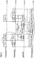
- an industrial technical process 1 is controlled by a control device 2.
- the industrial technical process 1 is, as in FIG. 1 is indicated by the schematic representation of a drill chuck and a drill, in the present case, a production process 1, namely a machining process 1 of a machine tool.
- a logical logic unit 3 of the control device 2 as numerical control 3 (CNC 3) formed.
- the logic unit 3 is programmed with a computer program 4, which is stored on a data carrier 5, for example a buffered SRAM, in (exclusively) machine-readable form. Due to the programming with the computer program 4, the control device 2 performs a following in connection with the FIG. 1 and 2 described in more detail real-time control method.
- a computer program 4 which is stored on a data carrier 5, for example a buffered SRAM, in (exclusively) machine-readable form. Due to the programming with the computer program 4, the control device 2 performs a following in connection with the FIG. 1 and 2 described in more detail real-time control method.
- status signals of the process 1 are detected by means of detection units.
- all state signals of the process 1 are detected via the detection units 6.
- the status signals thus represent in their entirety an image of the process 1.
- the logic unit 3 is common to all detection units 6. It transmits the image of the process 1 (or at least a part thereof) via a transmission medium 7 to a computing device 8.
- the detection units 6 and the logic unit 3 intelligent units can be arranged. Also, the detection units 6 themselves may have intelligence. However, the communication with the arithmetic unit 8 takes place exclusively by the logic unit 3.
- the logic unit 3 After transmitting the image of the process 1 to the computing device 8, the logic unit 3 takes from the computing device 8 via the transmission medium 7 a control state for process 1 (or at least part of it).
- the control state contains control signals for a number of control units 9. It transmits the control signals to the control units 9. These then act on the process 1 in accordance with the control signals transmitted to them.
- the cycle time T is in the millisecond range. Typically it is less than 20 ms. It is usually less than 1 ms and is for example about 100 ⁇ s .
- the arithmetic unit 8 is thus no longer permanently assigned (or identical to) to the logic unit 3 in contrast to the prior art, but correspondingly FIG. 1 connected to the logic unit 3 via the transmission medium 7.
- the computing device 8 can therefore be arranged at any location, if only through the transmission medium 7 of the required data exchange is possible.
- the transmission medium 7 can be configured as desired.
- LAN local area network
- IRTE industrial real time ethernet
- the transmission medium 7 is a point-to-point connection.
- An example of such a point-to-point connection is the telephone network.
- the computing device 8 itself is - see FIG. 1 - Also programmed with a computer program 10.
- This computer program 10 is also stored on a data carrier 11, for example a CD-ROM 11, and can be supplied to the computing device 8 in this manner. Due to the programming with the computer program 10, the computing device 8 carries out a real-time operating method, which is also described below with reference to FIGS FIG. 1 and 2 will be described in more detail.
- control program 12 corresponds to the industrial technical process 1. If the process 1 is a production process 1, for example a processing process 1 of a machine tool, the control program 12 is also a control program 12 for such a process 1.
- control program encompasses this only the application program, for example, a part program according to DIN 66025 in a machine tool program, but not an operating system. Rather, the (real-time) operating system is part of the computer program 10.
- the control state determined by the computing device 8 is finally transmitted to the logic unit 3 by the computing device 8 via the transmission medium 7.
- the computing device 8 performs the steps performed by it within the cycle time T.
- the cycle time T is the same cycle time T, with which the logic unit 3 executes its steps.
- the transmission medium 7 has two end sections 13, 14 and a central section 15.
- the end sections 13, 14 there is a cable-bound data transmission, eg via copper wires or optical waveguides.
- the middle section 15 is a wireless data transmission, eg via a radio link. But it is also another type of wireless data transmission, z. B. by infrared signals or ultrasonic signals, conceivable.
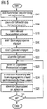
- the logic unit 3 and the computing device 8 not only perform the above in connection with the FIG. 1 and 2 described tasks. Other tasks performed by the logic unit 3 and the computing device 8 are described below in connection with the FIG. 4 and 5 explained in more detail.
- the FIG. 4 refers to the logic unit 3, the FIG. 5 to the computing device 8.
- the logic unit 3 first establishes a communication connection with the computing device 8 in a step S1.
- step S2 the logic unit 3 receives a real-time part of the computer program 4 from the computer 8 via the transmission medium 7 and stores it in the data carrier 5.
- step S2 is only optional and therefore in FIG. 4 shown only by dashed lines.
- the logic unit 3 transmits relevant parameter data via the transmission medium 7, such as, for example, the concrete assembly and disassembly of the machine. by means of which the process 1 is realized, to the computing device 8.
- step S4 the logic unit 3 transmits the control program 12 to the computing device 8 via the transmission medium 7.
- the step S4 is also optional and therefore in FIG FIG. 4 shown only by dashed lines.
- step S5 the logic unit 3 finally transmits the cycle time T via the transmission medium 7 to the computing device 8.
- the logic unit 3 may also receive the cycle time T via the transmission medium 7 from the computing unit 8.
- the cycle time T could alternatively be preset. Of the steps S5 and S6 so maximum one is executed.
- step S7 the logic unit 3 assumes the state signals detected by the detection units 6.
- step S8 it transmits the image of the process 1 via the transmission medium 7 to the computing device 8.
- the logic unit 3 carries out a determination of the remaining control state in a step S9.
- the step S9 is therefore not necessarily present and therefore also shown only by dashed lines.
- step S10 the logic unit 3 receives the control state transmitted by the computing device 8 via the transmission medium 7.
- step S11 the logic unit 3 checks whether the control device transmits the control state to it. If this is the case, the logic unit 3 in step S12, the control signals to the control units 9 on and jumps to Step S7 back. Otherwise, the logic unit 3 in step S13 itself determines emergency output signals and transmits them in a step S14 to the control units 9. Thus, even if the control signals are absent, it is ensured that the logic unit 3 controls the process 1 in a defined manner, eg an emergency operation of the process 1 maintains.
- step S14 it is checked in step S15 whether a limit number of transmission attempts has been exceeded. If this is not the case, the process returns to step S7. Otherwise, the operation of the process 1 is set in a step S16.
- FIG. 5 shown executed by the computing device 8 corresponds essentially to the in FIG. 4 shown, performed by the logic unit 3 sequence.
- the computing device 8 also initially establishes the communication connection to the logic unit 3 in a step S17.
- a step S18 it transmits the real-time part of the computer program 4.
- the step S18 is the same as the step S2 of FIG. 4 - only optional and therefore in FIG. 5 shown only by dashed lines.
- the computing device 8 receives the relevant parameter data, for example via the specific structure and the expansion of the controlled machine. Furthermore, it receives the control program 12 in a step S20.
- the step S20 is - as well as the step S4 of FIG. 4 - only optional and therefore in FIG. 5 shown only by dashed lines.
- the computing device 8 still accepts the cycle time T in a step S21.
- the computing device 8 could also transmit the cycle time T to the logic unit 3 in a step S22.
- the cycle time could be T be fixed. Also, of the steps S21 and S22, therefore, at most one is executed.
- step S23 the computing device 8 receives the image of the process 1 from the logic unit 3.
- step S24 the computing device 8 determines the control state for the process 1 by executing the control program 12 on the basis of the image of the process 1.
- step S25 the computing device 8 transmits the control state via the transmission medium 7 to the logic unit 8.
- step S26 the computing device 8 checks whether the transmission of the control state has been correct. For example, an acknowledgment can be queried by the logic unit 3. If the transmission is correct, the system jumps back to step S23, otherwise - if appropriate after several unsuccessful transmission attempts - the further processing of steps S23 to S26 is ended.
- control device 2 for a machine tool.
- the present invention is not limited to machine tools. It could also be used in other industrial technical processes 1, in which case the control device 2 may be designed differently.
- the control device 2 may be formed in this case as a programmable logic controller (PLC).
- PLC programmable logic controller
Landscapes
- Physics & Mathematics (AREA)
- General Physics & Mathematics (AREA)
- Engineering & Computer Science (AREA)
- Automation & Control Theory (AREA)
- Numerical Control (AREA)
- Programmable Controllers (AREA)
- Testing And Monitoring For Control Systems (AREA)
Claims (11)
- Procédé de fonctionnement en temps réel d'un dispositif (8) d'ordinateur, comprenant les stades suivants effectués de manière répétée suivant un temps de cycle, le temps de cycle étant dans le domaine de la milliseconde ou inférieur :a) le dispositif (8) d'ordinateur reçoit d'une unité (3) logique unique, par un support (7) de transmission, au moins une partie d'une reproduction d'un processus (1) technique industriel,b) le dispositif (8) d'ordinateur détermine, en élaborant un programme (12) de commande à l'aide de la partie qui lui a été transmise de la reproduction du processus (1), au moins une partie d'un état de commande du processus (1),c) le dispositif (8) d'ordinateur transmet la partie qu'il a déterminée de l'état de commande à l'unité (3) logique par le support (7) de transmission,- dans lequel le dispositif (8) d'ordinateur reçoit, avant le début de la réalisation cyclique des stades a) à c), le temps de cycle de l'unité (3) logique par le support (7) de transmission ou transmet à l'unité (3) logique le temps (T) de cycle par le support (7) de transmission.
- Procédé de fonctionnement en temps réel suivant la revendication 1, caractérisé en ce que le support (7) de transmission est un réseau (7) d'ordinateur, par exemple l'Internet ou un LAN.
- Procédé de fonctionnement en temps réel suivant la revendication 1, caractérisé en ce que le support (7) de transmission est une liaison (7) point à point.
- Procédé de fonctionnement en temps réel suivant la revendication 1, 2 ou 3, caractérisé en ce que le support (7) de transmission comprend au moins une partie (15) de support de transmission sans fil.
- Procédé de fonctionnement en temps réel suivant l'une des revendications 1 à 4, caractérisé en ce que le support (7) de transmission comprend au moins une partie (13, 14) de support de transmission par fil.
- Procédé de fonctionnement en temps réel suivant l'une des revendications 1 à 5, caractérisé en ce que le programme (12) de commande est un programme (12) de commande d'un processus (1) de production, notamment d'un processus (1) d'usinage d'une machine-outil.
- Procédé de fonctionnement en temps réel suivant l'une des revendications 1 à 6, caractérisé en ce que le dispositif (8) d'ordinateur transmet à l'unité (3) logique, avant le début de la réalisation cyclique des stades mentionnés à la revendication 1, une partie en temps réel d'un programme (4) d'ordinateur à réaliser par l'unité (3) logique.
- Procédé de fonctionnement en temps réel suivant l'une des revendications 1 à 7, caractérisé en ce que le dispositif (8) d'ordinateur reçoit de l'unité (3) logique, avant le début de la réalisation cyclique des stades mentionnés à la revendication 1, des données de paramètre du processus (1).
- Procédé de fonctionnement en temps réel suivant l'une des revendications 1 à 8, caractérisé en ce que le dispositif (8) d'ordinateur reçoit de l'unité (3) logique par le support (7) de transmission, le programme (12) d'ordinateur, avant le début de la réalisation cyclique des stades mentionnés à la revendication 1.
- Programme d'ordinateur mémorisé sur un support (1) de données pour effectuer un procédé de fonctionnement en temps réel suivant l'une des revendications 1 à 9.
- Dispositif d'ordinateur qui, en fonctionnement du dispositif d'ordinateur, coopère avec une unité (3) logique d'un dispositif (1) de commande, de manière à recevoir, avec un temps de cycle qui est dans le domaine de la milliseconde ou inférieur, de manière répétéea) de l'unité (3) logique, par un support (7) de transmission, au moins une partie d'une reproduction d'un processus (1) technique industriel,b) en élaborant un programme (12) de commande, à l'aide de la partie de la reproduction du processus (1) qu'il a transmise par l'unité (3) logique, détermine au moins une partie d'un état de commande du processus (1) etc) transmet la partie qu'il a déterminée de l'état de commande à l'unité (3) logique par le support (7) de transmission,- dans lequel le dispositif (8) d'ordinateur reçoit de l'unité (8) logique, par le support (7) de transmission, le temps de cycle, avant le début de la réalisation cyclique des stades a) à c) ou transmet le temps (T) de cycle à l'unité (3) logique par le support (7) de transmission.
Applications Claiming Priority (2)
| Application Number | Priority Date | Filing Date | Title |
|---|---|---|---|
| DE10340403A DE10340403A1 (de) | 2003-09-02 | 2003-09-02 | Echtzeitsteuerverfahren für eine Steuerungseinrichtung eines industriellen technischen Prozesses und Echtzeitbetriebsverfahren für eine Recheneinrichtung |
| EP04019104A EP1513035B1 (fr) | 2003-09-02 | 2004-08-11 | Méthode de commande en temps réel pour un dispositif de commande d'un processus industriel et méthode de commande en temps réel pour un ordinateur |
Related Parent Applications (2)
| Application Number | Title | Priority Date | Filing Date |
|---|---|---|---|
| EP04019104A Division EP1513035B1 (fr) | 2003-09-02 | 2004-08-11 | Méthode de commande en temps réel pour un dispositif de commande d'un processus industriel et méthode de commande en temps réel pour un ordinateur |
| EP04019104.1 Division | 2004-08-11 |
Publications (2)
| Publication Number | Publication Date |
|---|---|
| EP2315090A1 EP2315090A1 (fr) | 2011-04-27 |
| EP2315090B1 true EP2315090B1 (fr) | 2019-09-25 |
Family
ID=34129623
Family Applications (2)
| Application Number | Title | Priority Date | Filing Date |
|---|---|---|---|
| EP04019104A Revoked EP1513035B1 (fr) | 2003-09-02 | 2004-08-11 | Méthode de commande en temps réel pour un dispositif de commande d'un processus industriel et méthode de commande en temps réel pour un ordinateur |
| EP10011919.7A Expired - Lifetime EP2315090B1 (fr) | 2003-09-02 | 2004-08-11 | Méthode de commande en temps réel pour un dispositif de commande d'un processus industriel et méthode de commande en temps réel pour un ordinateur |
Family Applications Before (1)
| Application Number | Title | Priority Date | Filing Date |
|---|---|---|---|
| EP04019104A Revoked EP1513035B1 (fr) | 2003-09-02 | 2004-08-11 | Méthode de commande en temps réel pour un dispositif de commande d'un processus industriel et méthode de commande en temps réel pour un ordinateur |
Country Status (3)
| Country | Link |
|---|---|
| US (1) | US7058460B2 (fr) |
| EP (2) | EP1513035B1 (fr) |
| DE (1) | DE10340403A1 (fr) |
Families Citing this family (4)
| Publication number | Priority date | Publication date | Assignee | Title |
|---|---|---|---|---|
| JP2005108082A (ja) * | 2003-10-01 | 2005-04-21 | Okuma Corp | デバイスドライバのインターフェース方法 |
| JP4388427B2 (ja) * | 2004-07-02 | 2009-12-24 | オークマ株式会社 | スクリプト言語で記述されたプログラムを呼出し可能な数値制御装置 |
| US7706895B2 (en) * | 2005-02-25 | 2010-04-27 | Rockwell Automation Technologies, Inc. | Reliable messaging instruction |
| US7233830B1 (en) | 2005-05-31 | 2007-06-19 | Rockwell Automation Technologies, Inc. | Application and service management for industrial control devices |
Family Cites Families (8)
| Publication number | Priority date | Publication date | Assignee | Title |
|---|---|---|---|---|
| DE3534465A1 (de) * | 1985-09-27 | 1987-04-09 | Kloeckner Moeller Elektrizit | Verbundsystem speicherprogrammierbarer steuerungen |
| JPH06250869A (ja) * | 1993-03-01 | 1994-09-09 | Hitachi Ltd | 分散制御システム |
| US5530643A (en) * | 1993-08-24 | 1996-06-25 | Allen-Bradley Company, Inc. | Method of programming industrial controllers with highly distributed processing |
| US6175872B1 (en) * | 1997-12-12 | 2001-01-16 | Gte Internetworking Incorporated | Collaborative environment for syncronizing audio from remote devices |
| US6325198B1 (en) * | 1998-06-26 | 2001-12-04 | Eveready Battery Company, Inc. | High speed manufacturing system |
| DE19906695A1 (de) * | 1999-02-18 | 2000-08-31 | Wratil Peter | Verfahren zur automatischen Dezentralisierung von Programmen in Steuerungseinrichtungen und zur Verteilung von Intelligenz |
| WO2001001366A2 (fr) * | 1999-06-25 | 2001-01-04 | Telemonitor, Inc. | Procede et systeme de surveillance intelligent a distance |
| US20050004736A1 (en) * | 2003-04-30 | 2005-01-06 | Belcher Jack T. | Vehicle ground speed control system |
-
2003
- 2003-09-02 DE DE10340403A patent/DE10340403A1/de not_active Ceased
-
2004
- 2004-08-11 EP EP04019104A patent/EP1513035B1/fr not_active Revoked
- 2004-08-11 EP EP10011919.7A patent/EP2315090B1/fr not_active Expired - Lifetime
- 2004-09-02 US US10/933,130 patent/US7058460B2/en not_active Expired - Lifetime
Non-Patent Citations (1)
| Title |
|---|
| AVL LIST GMBH: "Puma Compact 5, Systemhandbuch", 1 September 1995 (1995-09-01), Österreich, pages 3 - 104, XP055187295, Retrieved from the Internet <URL:https://www.avl.com/search?p_p_id=3&_3_struts_action=%2Fsearch%2Fsearch&p_p_lifecycle=0&p_p_state=normal&p_p_mode=view&p_p_col_id=column-1&p_p_col_count=1&_3_groupId=10138&_3_category=All&_3_keywords=downloads&_3_search=> [retrieved on 20150504] * |
Also Published As
| Publication number | Publication date |
|---|---|
| EP1513035A3 (fr) | 2005-06-29 |
| EP1513035A2 (fr) | 2005-03-09 |
| EP2315090A1 (fr) | 2011-04-27 |
| US7058460B2 (en) | 2006-06-06 |
| DE10340403A1 (de) | 2005-04-07 |
| US20050055107A1 (en) | 2005-03-10 |
| EP1513035B1 (fr) | 2012-03-07 |
Similar Documents
| Publication | Publication Date | Title |
|---|---|---|
| EP0824231B1 (fr) | Système de fabrication | |
| EP1119434B1 (fr) | Dispositif regulateur pour appareil a souder | |
| EP2016470B1 (fr) | Terminal de commande pour l'echange d'informations avec un appareil sur site dans un systeme d'automatisation | |
| WO2014111417A1 (fr) | Dispositif de commande d'installation de moulage par injection, commandé par microprocesseur, pourvu d'un ordinateur de simulation | |
| EP2545417B1 (fr) | Procédé de remplacement d'un équipement de conduction existant dans un système d'automatisation par un nouvel équipement de conduction et système d'automatisation ainsi construit | |
| DE112006000533T5 (de) | Flexible Verbindung von Lehrvorrichtungen mit programmierbaren Steuervorrichtungen | |
| EP1068561B1 (fr) | Procede et dispositif de transmission de donnees proteges contre les defaillances | |
| DE10105668B4 (de) | Internet-Inline-Steuereinrichtung für eine Strickmaschine | |
| EP3067768B1 (fr) | Dispositif d'automatisation et système opérateur | |
| DE10129189A1 (de) | Mobile Bedieneinheit | |
| DE102013108910B4 (de) | Elektromagnetventilsteuervorrichtung | |
| EP2315090B1 (fr) | Méthode de commande en temps réel pour un dispositif de commande d'un processus industriel et méthode de commande en temps réel pour un ordinateur | |
| EP3082001B1 (fr) | Procédé d'extension d'un dispositif d'automatisation avec un virtuel appareil d'automatisation et dispositif d'automatisation | |
| EP0825502A1 (fr) | Système de commande | |
| EP2341405B1 (fr) | Procédé destiné au fonctionnement d'une machine | |
| EP3456486A1 (fr) | Surveillance diversitaire anti-collision redondante | |
| DE102008060118A1 (de) | Maschine mit aufsteckbarem Bediengerät | |
| DE69028811T2 (de) | Extern erweiterbare speicherprogrammierbare steuerung | |
| DE4446958A1 (de) | Programmierbare Steuerung und zugehöriges Kommunikationsverfahren mit exklusiver Steuerung | |
| DE102008060117A1 (de) | Maschine mit Bediengerät für sicherheitsrelevante Funktionen | |
| EP3712724A1 (fr) | Agencement d'automatisation, procédé de fonctionnement de l'agencement d'automatisation ainsi que programme informatique | |
| EP3739405A1 (fr) | Procédé et système d'exécution un programme logiciel | |
| EP2811349A1 (fr) | Procédé destiné au fonctionnement d'un système d'automatisation | |
| EP1165263B1 (fr) | Systeme de guidage pour laminoir, notamment pour train de laminoir | |
| EP3148121B1 (fr) | Procede d'insertion ou d'enlevement d'une commande dans un reseau et dispositif d'execution du procede |
Legal Events
| Date | Code | Title | Description |
|---|---|---|---|
| PUAI | Public reference made under article 153(3) epc to a published international application that has entered the european phase |
Free format text: ORIGINAL CODE: 0009012 |
|
| AC | Divisional application: reference to earlier application |
Ref document number: 1513035 Country of ref document: EP Kind code of ref document: P |
|
| AK | Designated contracting states |
Kind code of ref document: A1 Designated state(s): DE FR GB |
|
| 17P | Request for examination filed |
Effective date: 20110606 |
|
| 17Q | First examination report despatched |
Effective date: 20110817 |
|
| RAP1 | Party data changed (applicant data changed or rights of an application transferred) |
Owner name: SIEMENS AKTIENGESELLSCHAFT |
|
| RAP1 | Party data changed (applicant data changed or rights of an application transferred) |
Owner name: SIEMENS AKTIENGESELLSCHAFT |
|
| GRAP | Despatch of communication of intention to grant a patent |
Free format text: ORIGINAL CODE: EPIDOSNIGR1 |
|
| INTG | Intention to grant announced |
Effective date: 20190416 |
|
| GRAS | Grant fee paid |
Free format text: ORIGINAL CODE: EPIDOSNIGR3 |
|
| GRAA | (expected) grant |
Free format text: ORIGINAL CODE: 0009210 |
|
| AC | Divisional application: reference to earlier application |
Ref document number: 1513035 Country of ref document: EP Kind code of ref document: P |
|
| AK | Designated contracting states |
Kind code of ref document: B1 Designated state(s): DE FR GB |
|
| REG | Reference to a national code |
Ref country code: GB Ref legal event code: FG4D Free format text: NOT ENGLISH |
|
| REG | Reference to a national code |
Ref country code: DE Ref legal event code: R096 Ref document number: 502004015825 Country of ref document: DE |
|
| REG | Reference to a national code |
Ref country code: DE Ref legal event code: R097 Ref document number: 502004015825 Country of ref document: DE |
|
| PLBE | No opposition filed within time limit |
Free format text: ORIGINAL CODE: 0009261 |
|
| STAA | Information on the status of an ep patent application or granted ep patent |
Free format text: STATUS: NO OPPOSITION FILED WITHIN TIME LIMIT |
|
| 26N | No opposition filed |
Effective date: 20200626 |
|
| GBPC | Gb: european patent ceased through non-payment of renewal fee |
Effective date: 20200811 |
|
| PG25 | Lapsed in a contracting state [announced via postgrant information from national office to epo] |
Ref country code: GB Free format text: LAPSE BECAUSE OF NON-PAYMENT OF DUE FEES Effective date: 20200811 |
|
| PGFP | Annual fee paid to national office [announced via postgrant information from national office to epo] |
Ref country code: FR Payment date: 20230822 Year of fee payment: 20 |
|
| PGFP | Annual fee paid to national office [announced via postgrant information from national office to epo] |
Ref country code: DE Payment date: 20231019 Year of fee payment: 20 |
|
| REG | Reference to a national code |
Ref country code: DE Ref legal event code: R071 Ref document number: 502004015825 Country of ref document: DE |