EP2316558B1 - Verfahren und Vorrichtung zur Speicherung und Abgabe von Ammoniak mit in-situ-Auffüllen der Abgabeeinheit - Google Patents
Verfahren und Vorrichtung zur Speicherung und Abgabe von Ammoniak mit in-situ-Auffüllen der Abgabeeinheit Download PDFInfo
- Publication number
- EP2316558B1 EP2316558B1 EP10011305.9A EP10011305A EP2316558B1 EP 2316558 B1 EP2316558 B1 EP 2316558B1 EP 10011305 A EP10011305 A EP 10011305A EP 2316558 B1 EP2316558 B1 EP 2316558B1
- Authority
- EP
- European Patent Office
- Prior art keywords
- ammonia
- storage container
- storage material
- storage
- heating
- Prior art date
- Legal status (The legal status is an assumption and is not a legal conclusion. Google has not performed a legal analysis and makes no representation as to the accuracy of the status listed.)
- Not-in-force
Links
Images


Classifications
-
- C—CHEMISTRY; METALLURGY
- C01—INORGANIC CHEMISTRY
- C01C—AMMONIA; CYANOGEN; COMPOUNDS THEREOF
- C01C1/00—Ammonia; Compounds thereof
- C01C1/02—Preparation, purification or separation of ammonia
-
- B—PERFORMING OPERATIONS; TRANSPORTING
- B01—PHYSICAL OR CHEMICAL PROCESSES OR APPARATUS IN GENERAL
- B01D—SEPARATION
- B01D53/00—Separation of gases or vapours; Recovering vapours of volatile solvents from gases; Chemical or biological purification of waste gases, e.g. engine exhaust gases, smoke, fumes, flue gases, aerosols
- B01D53/02—Separation of gases or vapours; Recovering vapours of volatile solvents from gases; Chemical or biological purification of waste gases, e.g. engine exhaust gases, smoke, fumes, flue gases, aerosols by adsorption, e.g. preparative gas chromatography
-
- B—PERFORMING OPERATIONS; TRANSPORTING
- B01—PHYSICAL OR CHEMICAL PROCESSES OR APPARATUS IN GENERAL
- B01D—SEPARATION
- B01D53/00—Separation of gases or vapours; Recovering vapours of volatile solvents from gases; Chemical or biological purification of waste gases, e.g. engine exhaust gases, smoke, fumes, flue gases, aerosols
- B01D53/02—Separation of gases or vapours; Recovering vapours of volatile solvents from gases; Chemical or biological purification of waste gases, e.g. engine exhaust gases, smoke, fumes, flue gases, aerosols by adsorption, e.g. preparative gas chromatography
- B01D53/04—Separation of gases or vapours; Recovering vapours of volatile solvents from gases; Chemical or biological purification of waste gases, e.g. engine exhaust gases, smoke, fumes, flue gases, aerosols by adsorption, e.g. preparative gas chromatography with stationary adsorbents
- B01D53/0407—Constructional details of adsorbing systems
-
- B—PERFORMING OPERATIONS; TRANSPORTING
- B01—PHYSICAL OR CHEMICAL PROCESSES OR APPARATUS IN GENERAL
- B01D—SEPARATION
- B01D53/00—Separation of gases or vapours; Recovering vapours of volatile solvents from gases; Chemical or biological purification of waste gases, e.g. engine exhaust gases, smoke, fumes, flue gases, aerosols
- B01D53/34—Chemical or biological purification of waste gases
- B01D53/74—General processes for purification of waste gases; Apparatus or devices specially adapted therefor
- B01D53/86—Catalytic processes
- B01D53/8621—Removing nitrogen compounds
- B01D53/8625—Nitrogen oxides
-
- B—PERFORMING OPERATIONS; TRANSPORTING
- B01—PHYSICAL OR CHEMICAL PROCESSES OR APPARATUS IN GENERAL
- B01D—SEPARATION
- B01D53/00—Separation of gases or vapours; Recovering vapours of volatile solvents from gases; Chemical or biological purification of waste gases, e.g. engine exhaust gases, smoke, fumes, flue gases, aerosols
- B01D53/34—Chemical or biological purification of waste gases
- B01D53/74—General processes for purification of waste gases; Apparatus or devices specially adapted therefor
- B01D53/86—Catalytic processes
- B01D53/90—Injecting reactants
-
- B—PERFORMING OPERATIONS; TRANSPORTING
- B01—PHYSICAL OR CHEMICAL PROCESSES OR APPARATUS IN GENERAL
- B01D—SEPARATION
- B01D53/00—Separation of gases or vapours; Recovering vapours of volatile solvents from gases; Chemical or biological purification of waste gases, e.g. engine exhaust gases, smoke, fumes, flue gases, aerosols
- B01D53/34—Chemical or biological purification of waste gases
- B01D53/92—Chemical or biological purification of waste gases of engine exhaust gases
- B01D53/94—Chemical or biological purification of waste gases of engine exhaust gases by catalytic processes
- B01D53/9404—Removing only nitrogen compounds
- B01D53/9409—Nitrogen oxides
-
- B—PERFORMING OPERATIONS; TRANSPORTING
- B01—PHYSICAL OR CHEMICAL PROCESSES OR APPARATUS IN GENERAL
- B01D—SEPARATION
- B01D53/00—Separation of gases or vapours; Recovering vapours of volatile solvents from gases; Chemical or biological purification of waste gases, e.g. engine exhaust gases, smoke, fumes, flue gases, aerosols
- B01D53/34—Chemical or biological purification of waste gases
- B01D53/92—Chemical or biological purification of waste gases of engine exhaust gases
- B01D53/94—Chemical or biological purification of waste gases of engine exhaust gases by catalytic processes
- B01D53/9404—Removing only nitrogen compounds
- B01D53/9409—Nitrogen oxides
- B01D53/9431—Processes characterised by a specific device
-
- C—CHEMISTRY; METALLURGY
- C01—INORGANIC CHEMISTRY
- C01C—AMMONIA; CYANOGEN; COMPOUNDS THEREOF
- C01C1/00—Ammonia; Compounds thereof
- C01C1/003—Storage or handling of ammonia
- C01C1/006—Storage or handling of ammonia making use of solid ammonia storage materials, e.g. complex ammine salts
-
- F—MECHANICAL ENGINEERING; LIGHTING; HEATING; WEAPONS; BLASTING
- F01—MACHINES OR ENGINES IN GENERAL; ENGINE PLANTS IN GENERAL; STEAM ENGINES
- F01N—GAS-FLOW SILENCERS OR EXHAUST APPARATUS FOR MACHINES OR ENGINES IN GENERAL; GAS-FLOW SILENCERS OR EXHAUST APPARATUS FOR INTERNAL-COMBUSTION ENGINES
- F01N3/00—Exhaust or silencing apparatus having means for purifying, rendering innocuous, or otherwise treating exhaust
- F01N3/08—Exhaust or silencing apparatus having means for purifying, rendering innocuous, or otherwise treating exhaust for rendering innocuous
- F01N3/10—Exhaust or silencing apparatus having means for purifying, rendering innocuous, or otherwise treating exhaust for rendering innocuous by thermal or catalytic conversion of noxious components of exhaust
- F01N3/18—Exhaust or silencing apparatus having means for purifying, rendering innocuous, or otherwise treating exhaust for rendering innocuous by thermal or catalytic conversion of noxious components of exhaust characterised by methods of operation; Control
- F01N3/20—Exhaust or silencing apparatus having means for purifying, rendering innocuous, or otherwise treating exhaust for rendering innocuous by thermal or catalytic conversion of noxious components of exhaust characterised by methods of operation; Control specially adapted for catalytic conversion
- F01N3/206—Adding periodically or continuously substances to exhaust gases for promoting purification, e.g. catalytic material in liquid form, NOx reducing agents
- F01N3/2066—Selective catalytic reduction [SCR]
-
- F—MECHANICAL ENGINEERING; LIGHTING; HEATING; WEAPONS; BLASTING
- F17—STORING OR DISTRIBUTING GASES OR LIQUIDS
- F17C—VESSELS FOR CONTAINING OR STORING COMPRESSED, LIQUEFIED OR SOLIDIFIED GASES; FIXED-CAPACITY GAS-HOLDERS; FILLING VESSELS WITH, OR DISCHARGING FROM VESSELS, COMPRESSED, LIQUEFIED, OR SOLIDIFIED GASES
- F17C11/00—Use of gas-solvents or gas-sorbents in vessels
-
- H—ELECTRICITY
- H01—ELECTRIC ELEMENTS
- H01M—PROCESSES OR MEANS, e.g. BATTERIES, FOR THE DIRECT CONVERSION OF CHEMICAL ENERGY INTO ELECTRICAL ENERGY
- H01M8/00—Fuel cells; Manufacture thereof
- H01M8/04—Auxiliary arrangements, e.g. for control of pressure or for circulation of fluids
- H01M8/04082—Arrangements for control of reactant parameters, e.g. pressure or concentration
- H01M8/04201—Reactant storage and supply, e.g. means for feeding, pipes
- H01M8/04208—Cartridges, cryogenic media or cryogenic reservoirs
-
- H—ELECTRICITY
- H01—ELECTRIC ELEMENTS
- H01M—PROCESSES OR MEANS, e.g. BATTERIES, FOR THE DIRECT CONVERSION OF CHEMICAL ENERGY INTO ELECTRICAL ENERGY
- H01M8/00—Fuel cells; Manufacture thereof
- H01M8/04—Auxiliary arrangements, e.g. for control of pressure or for circulation of fluids
- H01M8/04082—Arrangements for control of reactant parameters, e.g. pressure or concentration
- H01M8/04201—Reactant storage and supply, e.g. means for feeding, pipes
- H01M8/04216—Reactant storage and supply, e.g. means for feeding, pipes characterised by the choice for a specific material, e.g. carbon, hydride, absorbent
-
- H—ELECTRICITY
- H01—ELECTRIC ELEMENTS
- H01M—PROCESSES OR MEANS, e.g. BATTERIES, FOR THE DIRECT CONVERSION OF CHEMICAL ENERGY INTO ELECTRICAL ENERGY
- H01M8/00—Fuel cells; Manufacture thereof
- H01M8/06—Combination of fuel cells with means for production of reactants or for treatment of residues
- H01M8/0606—Combination of fuel cells with means for production of reactants or for treatment of residues with means for production of gaseous reactants
-
- H—ELECTRICITY
- H01—ELECTRIC ELEMENTS
- H01M—PROCESSES OR MEANS, e.g. BATTERIES, FOR THE DIRECT CONVERSION OF CHEMICAL ENERGY INTO ELECTRICAL ENERGY
- H01M8/00—Fuel cells; Manufacture thereof
- H01M8/22—Fuel cells in which the fuel is based on materials comprising carbon or oxygen or hydrogen and other elements; Fuel cells in which the fuel is based on materials comprising only elements other than carbon, oxygen or hydrogen
- H01M8/222—Fuel cells in which the fuel is based on compounds containing nitrogen, e.g. hydrazine, ammonia
-
- B—PERFORMING OPERATIONS; TRANSPORTING
- B01—PHYSICAL OR CHEMICAL PROCESSES OR APPARATUS IN GENERAL
- B01D—SEPARATION
- B01D2251/00—Reactants
- B01D2251/20—Reductants
- B01D2251/206—Ammonium compounds
- B01D2251/2062—Ammonia
-
- B—PERFORMING OPERATIONS; TRANSPORTING
- B01—PHYSICAL OR CHEMICAL PROCESSES OR APPARATUS IN GENERAL
- B01D—SEPARATION
- B01D2253/00—Adsorbents used in seperation treatment of gases and vapours
- B01D2253/10—Inorganic adsorbents
-
- B—PERFORMING OPERATIONS; TRANSPORTING
- B01—PHYSICAL OR CHEMICAL PROCESSES OR APPARATUS IN GENERAL
- B01D—SEPARATION
- B01D2253/00—Adsorbents used in seperation treatment of gases and vapours
- B01D2253/20—Organic adsorbents
-
- B—PERFORMING OPERATIONS; TRANSPORTING
- B01—PHYSICAL OR CHEMICAL PROCESSES OR APPARATUS IN GENERAL
- B01D—SEPARATION
- B01D2257/00—Components to be removed
- B01D2257/40—Nitrogen compounds
- B01D2257/406—Ammonia
-
- B—PERFORMING OPERATIONS; TRANSPORTING
- B01—PHYSICAL OR CHEMICAL PROCESSES OR APPARATUS IN GENERAL
- B01D—SEPARATION
- B01D2259/00—Type of treatment
- B01D2259/45—Gas separation or purification devices adapted for specific applications
- B01D2259/4525—Gas separation or purification devices adapted for specific applications for storage and dispensing systems
-
- F—MECHANICAL ENGINEERING; LIGHTING; HEATING; WEAPONS; BLASTING
- F01—MACHINES OR ENGINES IN GENERAL; ENGINE PLANTS IN GENERAL; STEAM ENGINES
- F01N—GAS-FLOW SILENCERS OR EXHAUST APPARATUS FOR MACHINES OR ENGINES IN GENERAL; GAS-FLOW SILENCERS OR EXHAUST APPARATUS FOR INTERNAL-COMBUSTION ENGINES
- F01N2610/00—Adding substances to exhaust gases
- F01N2610/02—Adding substances to exhaust gases the substance being ammonia or urea
-
- F—MECHANICAL ENGINEERING; LIGHTING; HEATING; WEAPONS; BLASTING
- F01—MACHINES OR ENGINES IN GENERAL; ENGINE PLANTS IN GENERAL; STEAM ENGINES
- F01N—GAS-FLOW SILENCERS OR EXHAUST APPARATUS FOR MACHINES OR ENGINES IN GENERAL; GAS-FLOW SILENCERS OR EXHAUST APPARATUS FOR INTERNAL-COMBUSTION ENGINES
- F01N2610/00—Adding substances to exhaust gases
- F01N2610/06—Adding substances to exhaust gases the substance being in the gaseous form
-
- F—MECHANICAL ENGINEERING; LIGHTING; HEATING; WEAPONS; BLASTING
- F01—MACHINES OR ENGINES IN GENERAL; ENGINE PLANTS IN GENERAL; STEAM ENGINES
- F01N—GAS-FLOW SILENCERS OR EXHAUST APPARATUS FOR MACHINES OR ENGINES IN GENERAL; GAS-FLOW SILENCERS OR EXHAUST APPARATUS FOR INTERNAL-COMBUSTION ENGINES
- F01N2610/00—Adding substances to exhaust gases
- F01N2610/10—Adding substances to exhaust gases the substance being heated, e.g. by heating tank or supply line of the added substance
-
- F—MECHANICAL ENGINEERING; LIGHTING; HEATING; WEAPONS; BLASTING
- F01—MACHINES OR ENGINES IN GENERAL; ENGINE PLANTS IN GENERAL; STEAM ENGINES
- F01N—GAS-FLOW SILENCERS OR EXHAUST APPARATUS FOR MACHINES OR ENGINES IN GENERAL; GAS-FLOW SILENCERS OR EXHAUST APPARATUS FOR INTERNAL-COMBUSTION ENGINES
- F01N2610/00—Adding substances to exhaust gases
- F01N2610/11—Adding substances to exhaust gases the substance or part of the dosing system being cooled
-
- F—MECHANICAL ENGINEERING; LIGHTING; HEATING; WEAPONS; BLASTING
- F01—MACHINES OR ENGINES IN GENERAL; ENGINE PLANTS IN GENERAL; STEAM ENGINES
- F01N—GAS-FLOW SILENCERS OR EXHAUST APPARATUS FOR MACHINES OR ENGINES IN GENERAL; GAS-FLOW SILENCERS OR EXHAUST APPARATUS FOR INTERNAL-COMBUSTION ENGINES
- F01N2610/00—Adding substances to exhaust gases
- F01N2610/14—Arrangements for the supply of substances, e.g. conduits
-
- F—MECHANICAL ENGINEERING; LIGHTING; HEATING; WEAPONS; BLASTING
- F01—MACHINES OR ENGINES IN GENERAL; ENGINE PLANTS IN GENERAL; STEAM ENGINES
- F01N—GAS-FLOW SILENCERS OR EXHAUST APPARATUS FOR MACHINES OR ENGINES IN GENERAL; GAS-FLOW SILENCERS OR EXHAUST APPARATUS FOR INTERNAL-COMBUSTION ENGINES
- F01N2610/00—Adding substances to exhaust gases
- F01N2610/14—Arrangements for the supply of substances, e.g. conduits
- F01N2610/1406—Storage means for substances, e.g. tanks or reservoirs
-
- H—ELECTRICITY
- H01—ELECTRIC ELEMENTS
- H01M—PROCESSES OR MEANS, e.g. BATTERIES, FOR THE DIRECT CONVERSION OF CHEMICAL ENERGY INTO ELECTRICAL ENERGY
- H01M8/00—Fuel cells; Manufacture thereof
- H01M8/10—Fuel cells with solid electrolytes
- H01M8/12—Fuel cells with solid electrolytes operating at high temperature, e.g. with stabilised ZrO2 electrolyte
- H01M2008/1293—Fuel cells with solid oxide electrolytes
-
- Y—GENERAL TAGGING OF NEW TECHNOLOGICAL DEVELOPMENTS; GENERAL TAGGING OF CROSS-SECTIONAL TECHNOLOGIES SPANNING OVER SEVERAL SECTIONS OF THE IPC; TECHNICAL SUBJECTS COVERED BY FORMER USPC CROSS-REFERENCE ART COLLECTIONS [XRACs] AND DIGESTS
- Y02—TECHNOLOGIES OR APPLICATIONS FOR MITIGATION OR ADAPTATION AGAINST CLIMATE CHANGE
- Y02A—TECHNOLOGIES FOR ADAPTATION TO CLIMATE CHANGE
- Y02A50/00—TECHNOLOGIES FOR ADAPTATION TO CLIMATE CHANGE in human health protection, e.g. against extreme weather
- Y02A50/20—Air quality improvement or preservation, e.g. vehicle emission control or emission reduction by using catalytic converters
-
- Y—GENERAL TAGGING OF NEW TECHNOLOGICAL DEVELOPMENTS; GENERAL TAGGING OF CROSS-SECTIONAL TECHNOLOGIES SPANNING OVER SEVERAL SECTIONS OF THE IPC; TECHNICAL SUBJECTS COVERED BY FORMER USPC CROSS-REFERENCE ART COLLECTIONS [XRACs] AND DIGESTS
- Y02—TECHNOLOGIES OR APPLICATIONS FOR MITIGATION OR ADAPTATION AGAINST CLIMATE CHANGE
- Y02E—REDUCTION OF GREENHOUSE GAS [GHG] EMISSIONS, RELATED TO ENERGY GENERATION, TRANSMISSION OR DISTRIBUTION
- Y02E60/00—Enabling technologies; Technologies with a potential or indirect contribution to GHG emissions mitigation
- Y02E60/30—Hydrogen technology
- Y02E60/50—Fuel cells
-
- Y—GENERAL TAGGING OF NEW TECHNOLOGICAL DEVELOPMENTS; GENERAL TAGGING OF CROSS-SECTIONAL TECHNOLOGIES SPANNING OVER SEVERAL SECTIONS OF THE IPC; TECHNICAL SUBJECTS COVERED BY FORMER USPC CROSS-REFERENCE ART COLLECTIONS [XRACs] AND DIGESTS
- Y02—TECHNOLOGIES OR APPLICATIONS FOR MITIGATION OR ADAPTATION AGAINST CLIMATE CHANGE
- Y02P—CLIMATE CHANGE MITIGATION TECHNOLOGIES IN THE PRODUCTION OR PROCESSING OF GOODS
- Y02P20/00—Technologies relating to chemical industry
- Y02P20/50—Improvements relating to the production of bulk chemicals
-
- Y—GENERAL TAGGING OF NEW TECHNOLOGICAL DEVELOPMENTS; GENERAL TAGGING OF CROSS-SECTIONAL TECHNOLOGIES SPANNING OVER SEVERAL SECTIONS OF THE IPC; TECHNICAL SUBJECTS COVERED BY FORMER USPC CROSS-REFERENCE ART COLLECTIONS [XRACs] AND DIGESTS
- Y02—TECHNOLOGIES OR APPLICATIONS FOR MITIGATION OR ADAPTATION AGAINST CLIMATE CHANGE
- Y02T—CLIMATE CHANGE MITIGATION TECHNOLOGIES RELATED TO TRANSPORTATION
- Y02T10/00—Road transport of goods or passengers
- Y02T10/10—Internal combustion engine [ICE] based vehicles
- Y02T10/12—Improving ICE efficiencies
Definitions
- This invention relates to a method and device for storing and generating of ammonia from storage materials capable of binding and releasing ammonia reversibly.
- the storage materials are solid metal ammine complexes capable of binding and releasing ammonia reversibly.
- the method and device may be used in the selective catalytic reduction of NOx.
- metal ammine salts can be used as a solid storage media for ammonia which in turn may be used as the reductant in selective catalytic reduction to reduce NO x emissions from automotive vehicles, boilers and furnaces.
- the metalammine salt constitutes a solid storage medium for ammonia, which represent a safe and practical option for storage and transportation of ammonia. This is advantageous compared with NOx removal using ammonia delivered as aqueous solution of urea or ammonia because the large fraction - typically more than 65% - of water is avoided.
- Mg(NH 3 )Cl 2 represents an ammonia storage material characterized by a high degree of safety because the vapor pressure at room temperature is below 0.1 bar. It is also characterized by a high mass density of ammonia because Mg is a light metal. Applicant's co-pending application ( WO2006081824 ) discloses further storage materials with a high, demonstrated volumetric capacity and method of making them.
- WO 99/01205 discloses a method and a device for selective catalytic NOx reduction in waste gases containing oxygen, using ammonia and a reduction catalyst.
- gaseous ammonia is provided by heating a solid storage medium preferably being granulated material consisting of Ca(NH 3 ) 8 Cl 2 or Sr(NH 3 ) 8 Cl 2 .
- WO 99/01205 A1 discloses a method and a device for selective catalytic NOx reduction in waste gases containing oxygen by means of a reduction catalyst and ammonia as a reductant which may be provided by heating salts binding ammonia in the form of a complex.
- the device may comprise a buffer container for gaseous ammonia.
- WO 2006/08182 A2 a device is shown that comprises three containers each equipped with heating means and a valve and each containing an ammonia storage and delivery material.
- the individual containers are heated sequentially for release of ammonia, and the valve of the individual heated container is opened for the release thereof.
- the present invention is based on having a large container that has heating means and contains a metal ammine salt ammonia storage material and a smaller container that also contains a metal ammine salt ammonia storage material and has heating means in order to release ammonia wherein the two ammonia storage materials are the same materials.
- the small container has been partially or fully degassed during a period of heating, e.g. while driving for say 1 hour, the unit is allowed to cool down to room temperature, which causes that a pressure gradient between the two storage containers is created. If the two containers have a connecting tube with an open/close valve in between, the smaller unit can absorb ammonia from the larger unit.
- the operation of the smaller heated container with the limited capacity is used periodically, and in between use, the smaller container may be passively re-saturated by opening a connection to the larger container.
- the two materials have different saturation pressures, then there will be a driving force for ammonia migration from the large container to the smaller - and partially of fully degassed - container.
- the energy that is put into the heated system during a period of degassing is partially recovered because the recharging may be done passively using a gradient in chemical potential of ammonia stored in a solid.
- the invention relates to a method for storing ammonia and delivering ammonia as defined in claim 1.
- the invention relates to a system for providing ammonia to an NOx removing device as defined in claim 5.
- the present invention relates to a system and a method for ammonia storage and delivery which may e.g. be on-board where the storage capacity is divided into at least two containers.
- the system of the present invention thus comprises:
- the invention also relates to the method and system as mentioned above where the ammonia is used as reductant in selective catalytic reduction of NOx.
- the invention also relates to systems and methods using the utilizing the storage and release of ammonia for or including NOx reduction in exhaust gases from combustion processes or engines.
- Partial or full degassing of a smaller unit is reversed by ammonia migration from the larger container to the smaller unit.
- FIG. 1-3 shows three different embodiments of the invention where the total ammonia storage capacity is separated into two or more containers or compartments.
- Ammonia may be released from a least one unit, and at least one larger unit having means for heating (not shown) may be as a source for passive re-absorption of ammonia in the smaller unit that has means for heating.
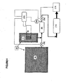
- Figure 4 which is not according to the invention is similar to figure 1 , except that it shows a fuel cell and an ammonia cracking catalyst instead of parts of an exhaust system of a combustion engine.
- the present invention is related to a method and system for ammonia storage and delivery that can e.g. be used for on-board storage and a delivery system for e.g. DeNOx by selective catalytic reduction using ammonia as the reductant. It may be used for other purposes requiring controlled dosing/delivery of ammonia from a compact storage unit.
- One aspect of the invention is a method for storing ammonia and delivering ammonia as claimed in claim 1.
- the fluid communication is interrupted while the second ammonia storage material is heated for desorption of ammonia, and the fluid communication is reassumed when the heating is stopped.
- Another aspect of the invention is a system for ammonia storage and delivery as claimed in claim 5.
- the storage containers contain ammonia stored as a metal ammine complex.
- the two metal ammine salt ammonia storage materials which are the same materials may be chosen from the group of materials known as metal ammine complexes of the general formula: M a (NH 3 ) n X z , wherein M is one or more cations selected from alkali metals such as Li, Na, K or Cs, alkaline earth metals such as Mg, Ca or Sr, and/or transition metals such as V, Cr, Mn, Fe, Co, Ni, Cu, or Zn or combinations thereof such as NaAl, KAl, K 2 Zn, CsCu, or K 2 Fe, X is one or more anions selected from fluoride, chloride, bromide, iodide, nitrate, thiocyanate, sulphate, molybdate, and phosphate ions, a is the number of cations per salt molecule, z is the number of anions per salt molecule, and n is the coordination number of 2 to 12.
- M is one or more cations selected
- the container with the first ammonia storage material is equipped with means for heating in order to increase the difference in ammonia pressure during the re-absorption phase when the two containers are otherwise kept at ambient temperature.
- the materials in the two containers are the same said method involving means for heating of the largest storage unit having the largest storage capacity of the two containers in order to increase the driving force for ammonia re-saturation.
- the storage container containing the first storage material may be insulated in order to decrease the rate of passive heating of the material inside when the storage unit is placed in a warm environment, i.e. at temperatures above 40-50°C, in order to reduce the rate of building up an ammonia desorption pressure above the level at room temperature (298K).
- ammonia containing material may be compacted to a unit, e.g. a dense block, rod, cylinder ring or edged unit, such as cube, with a density above 75% of the theoretical maximum skeleton density of the saturated solid material in order to fit inside a given storage volume of a container.
- a unit e.g. a dense block, rod, cylinder ring or edged unit, such as cube, with a density above 75% of the theoretical maximum skeleton density of the saturated solid material in order to fit inside a given storage volume of a container.
- the desorbed ammonia may be used in selective catalytic reduction of NOx in an oxygen-containing exhaust gas from a combustion process or engine.
- desorbed ammonia is delivered to a catalyst for a selective catalytic reduction of NO x in an oxygen-containing exhaust gas from a combustion process or engine.
- ammonia storage materials may have any or several of the features mentioned above.
- the system for providing ammonia to a NOx removing system has control means for controlling said first and second delivery means for the at least two same storage materials capable of releasing ammonia by desorption.
- ammonia adsorbing/absorbing material is selected from complex ammine coordinated compounds such as alkaline ammine complexed salts.
- a suitable device may comprise:
- the operating principle in the above example is the following:
- the smaller unit with e.g. Mg(NH 3 ) 6 Cl 2 (from item 2) is preferably built into the car as a fixed component that is never replaced.
- the Mg(NH 3 ) 6 Cl 2 -unit has used a given amount of ammonia thus becoming Mg(NH 3 ) x Cl 2 where x ⁇ 6 when the car is left for parking.
- the MgCl 2 -based unit cools down to room temperature, the ammonia pressure in the Mg(NH 3 ) x Cl 2 -unit will drop to the desorption pressure of the material at room temperature. This will create a chemically generated vacuum.
- the saturated Mg(NH 3 ) 6 Cl 2 has an ammonia pressure of approximately 2 mbar at room temperature.
- the smaller unit containing Mg(NH 3 ) x Cl 2 where x ⁇ 6 will pull ammonia from the storage material in the main tank and recharge the small MgCl 2 -based unit. After a given amount recharging time, the MgCl 2 -based unit is fully or partially refilled and ready for fast start-up and dosing.
- the main storage tank After e.g. 15,000 to 40,000km of operation, the main storage tank can be replaced.
- the system capacity can be scaled to an virtually "infinite" one:
- a base operational unit (item 2 above), which is designed to handle all normal driving situations and it is connected to the main tank.
- the main tank can - in principle - be of unlimited size. There is no technical barrier for making very large main-tanks to recharge the operational unit.
- the in-situ recharging of the present invention also works at all ambient temperature levels. If there is a driving force between the two materials at room temperature, then there is also one of similar magnitude at e.g. -30°C.
- FIG. 1 shows different embodiments of a system according to the present invention, wherein, however, the heating means for the main tank 4 is not shown.
- the main storage container(s) 4; 4a, 4b shown in Figs. 1 through 3 comprise an insulation to maintain an operation temperature between -40°C and 70°C.
- An optional temperature control means may also be provided to maintain the temperature of the storage material within the operational temperature range.
- the heating means for the second storage containers 1; 1a, 1b may either be operated by an independent heating source (e.g. electrical) and/or by the waste heat from a combustion engine. The same applies to the temperature control means (not shown) of the first storage containers 4; 4a, 4b.
- an independent heating source e.g. electrical
- the temperature control means not shown
- the valves 12; 12a to 12d; 12e, 12f and 13 may be of any type (e.g.: check valves, control valves, throttle valves, one-way valves) suitable to provide and to control the desired ammonia flow, either between the first and second storage containers 4; 4a, 4b and 1; 1a, 1b or from the second storage container 1; 1a, 1b to the ammonia consumption unit 8, 9 or to the buffer 5. Further pressure sensors 10 and/or flow detection means (not shown) may be provided to improve the control of the desired ammonia flow.
- Figure 4 (not according to the invention) is similar to figure 1 , except that it shows a fuel cell 15 and an ammonia cracking catalyst 14 instead of parts of an exhaust system of a combustion engine.
Landscapes
- Chemical & Material Sciences (AREA)
- Engineering & Computer Science (AREA)
- Chemical Kinetics & Catalysis (AREA)
- General Chemical & Material Sciences (AREA)
- Analytical Chemistry (AREA)
- Environmental & Geological Engineering (AREA)
- Oil, Petroleum & Natural Gas (AREA)
- Health & Medical Sciences (AREA)
- Life Sciences & Earth Sciences (AREA)
- Organic Chemistry (AREA)
- Biomedical Technology (AREA)
- Manufacturing & Machinery (AREA)
- Sustainable Development (AREA)
- Sustainable Energy (AREA)
- Electrochemistry (AREA)
- Combustion & Propulsion (AREA)
- Inorganic Chemistry (AREA)
- General Engineering & Computer Science (AREA)
- Mechanical Engineering (AREA)
- Toxicology (AREA)
- Exhaust Gas After Treatment (AREA)
- Filling Or Discharging Of Gas Storage Vessels (AREA)
Claims (9)
- Verfahren zur Speicherung und zur Lieferung von Ammoniak an eine NOx entfernende Vorrichtung (8,9) über ein Dosierventil (13) durch Erwärmen eines zweiten Metallamminsalz-Ammoniakspeichermaterials, das Ammoniak absorbieren und desorbieren kann und darin Ammoniak gespeichert aufweist, in einem zweiten Speicherbehälter (1; 1 a, 1 b), der mit einem Heizelement (3) versehen ist, wodurch Ammoniak desorbiert wird, bei dem ein erstes Metallamminsalz-Ammoniakspeichermaterial in einem größeren als der zweite Speicherbehälter (1; 1 a, 1 b) ersten Speicherbehälter (4; 4a, 4b), der mit dem zweiten Speicherbehälter (1; 1 a, 1 b) über eine Leitung verbunden ist, die ein Ventil (12; 12a, 12b, 12e, 12f), das während des Erwärmens des zweiten Ammoniakspeichermaterials geschlossen ist, oder ein geeignetes Einweg-Ventil umfasst, um zu verhindern, dass Ammoniak durch das erste Speichermaterial, das bei Raumtemperatur gehaltenen wird, absorbiert wird, wobei der erste Speicherbehälter (4; 4a, 4b), der größer ist als der zweite Speicherbehälter (1; 1 a, 1 b), als Ammoniakquelle für das zweite Ammoniakspeichermaterial in dem zweiten Speicherbehälter (1; 1 a, 1 b) verwendet wird, wenn das zweite Ammoniakspeichermaterial in dem zweiten Speicherbehälter (1; 1 a, 1 b) durch Verbrauch an Ammoniak abgereichert ist, das Erwärmen gestoppt worden ist und das Ventil (12; 12a, 12b, 12e, 12f) geöffnet ist, um eine Fluidkommunikation zwischen dem ersten Ammoniak-Speicherbehälter (4; 4a, 4b) und dem zweiten Ammoniak-Speicherbehälter (1; 1 a, 1 b) herzustellen, und wobei das erste und das zweite Ammoniakspeichermaterial die gleichen Materialien sind und der erste Speicherbehälter (4; 4a, 4b) mit Mitteln zum Erwärmen versehen ist, um die Triebkraft für die erneute Sättigung des zweiten Ammoniakspeichermaterials zu erhöhen, wenn das Letztgenannte an Ammoniak abgereichert ist.
- Verfahren nach Anspruch 1, bei dem das Metallamminsalz die allgemeine Formel:
Ma(NH3)nXz
aufweist, in der M für ein oder mehrere Kationen steht, die aus Alkalimetallen, wie Li, Na, K oder Cs, Erdalkalimetallen, wie Mg, Ca oder Sr, und/oder Übergangsmetallen, wie V, Cr, Mn, Fe, Co, Ni, Cu oder Zn, oder deren Kombinationen, wie NaAl, KAl, K2Zn, CsCu oder K2Fe, ausgewählt sind, X für ein oder mehrere Anionen steht, die aus Fluorid-, Chlorid-, Bromid-, Iodid-, Nitrat-, Thiocyanat-, Sulfat-, Molybdat- und Phosphationen ausgewählt sind, a die Zahl der Kationen pro Salzmolekül ist, z die Zahl der Anionen pro Salzmolekül ist und n die Koordinationszahl von 2 bis 12 ist. - Verfahren nach Anspruch 1 oder 2, bei dem das erste und/oder das zweite Metallamminsalz-Ammoniakspeichermaterial zu einer Einheit mit einer Dichte von oberhalb 75 % der theoretischen maximalen Skelettdichte des gesättigten Metallamminsalz-Ammoniakspeichermaterials kompaktiert ist.
- Verfahren nach einem der Ansprüche 1 bis 3, bei dem die NOx entfernende Vorrichtung ein Katalysator für eine selektive katalytische Reduktion von NOx in einem sauerstoffhaltigen Abgas aus einem Verbrennungsprozess oder einem Verbrennungsmotor ist.
- System zur Durchführung des Verfahrens nach irgendeinem der Ansprüche 1 bis 4, bei dem das System Ammoniak an eine NOx entfernende Einheit (8, 9) liefert und umfasst:einen ersten Speicherbehälter (4; 4a, 4b) mit einem ersten Metallamminsalz-Ammoniakspeichermaterial;einen zweiten Speicherbehälter (1; 1 a, 1 b), der kleiner als der erste Speicherbehälter ist, mit einem zweiten Metallamminsalz-Ammoniakspeichermaterial, wobei das zweite Metallamminsalz-Speichermaterial das gleiche ist wie das erste Metallamminsalz-Speichermaterial;Heizmittel zum Erwärmen des ersten Speicherbehälters (4; 4a, 4b), um die Triebkraft für die erneute Sättigung des zweiten Metallamminsalz-Ammoniakspeichermaterials in dem zweiten Speicherbehälter (1; 1 a, 1 b) mit Ammoniak zu erhöhen;Heizmittel (3) zum Erwärmen des zweiten Speichermaterials zur Freisetzung von Ammoniak aus dem zweiten Speicherbehälter (1; 1 a, 1 b);erste Mittel (5, 10, 13) zum Verbinden des zweiten Speicherbehälters (1; 1 a, 1 b) mit der Verbrauchereinheit (8, 9);zweite Mittel (12; 12a, 12b, 12c, 12d; 12e, 12f) zum Verbinden des ersten Speicherbehälters (4; 4a, 4b) mit dem zweiten Speicherbehälter (1; 1 a, 1 b), wobei das zweite Mittel ein Ventil (12; 12a, 12b, 12e, 12f) umfasst;gekennzeichnet durch Steuerungsmittel (11), die programmiert und angepasst sind, um das Verfahren von Anspruch 1 durchzuführen.
- System nach Anspruch 5, bei dem das erste Ammoniakspeichermaterial und das zweite Ammoniakspeichermaterial die Merkmale aufweisen, die in Anspruch 2 angegeben sind.
- System nach Anspruch 5 oder 6, bei dem das erste Ammoniakspeichermaterial und/oder das zweite Ammoniakspeichermaterial die Merkmale aufweisen, die in Anspruch 3 angegeben sind.
- System nach irgendeinem der Ansprüche 5 bis 7, bei dem der erste Speicherbehälter (4; 4a, 4b) isoliert ist.
- System nach irgendeinem der Ansprüche 5 bis 8, bei dem die NOx entfernende Vorrichtung ein Katalysator für eine selektive katalytische Reduktion von NOx in einem sauerstoffhaltigen Abgas eines Verbrennungsprozesses oder eines Verbrennungsmotors ist.
Applications Claiming Priority (3)
| Application Number | Priority Date | Filing Date | Title |
|---|---|---|---|
| DE102006061370A DE102006061370A1 (de) | 2006-12-22 | 2006-12-22 | Verfahren und Vorrichtung zur Ammoniakspeicherung und -zufuhr unter Verwendung von in-situ-Wiedersättigung einer Zufuhreinheit |
| US93963107P | 2007-05-23 | 2007-05-23 | |
| EP07857189.0A EP2107933B1 (de) | 2006-12-22 | 2007-12-21 | Verfahren und vorrichtung zur ammoniakspeicherung und zufuhr unter verwendung von in-situ-resaturierung einer zufuhreinheit |
Related Parent Applications (3)
| Application Number | Title | Priority Date | Filing Date |
|---|---|---|---|
| EP07857189.0 Division | 2007-12-21 | ||
| EP07857189.0A Division-Into EP2107933B1 (de) | 2006-12-22 | 2007-12-21 | Verfahren und vorrichtung zur ammoniakspeicherung und zufuhr unter verwendung von in-situ-resaturierung einer zufuhreinheit |
| EP07857189.0A Division EP2107933B1 (de) | 2006-12-22 | 2007-12-21 | Verfahren und vorrichtung zur ammoniakspeicherung und zufuhr unter verwendung von in-situ-resaturierung einer zufuhreinheit |
Publications (2)
| Publication Number | Publication Date |
|---|---|
| EP2316558A1 EP2316558A1 (de) | 2011-05-04 |
| EP2316558B1 true EP2316558B1 (de) | 2014-08-20 |
Family
ID=39431731
Family Applications (2)
| Application Number | Title | Priority Date | Filing Date |
|---|---|---|---|
| EP10011305.9A Not-in-force EP2316558B1 (de) | 2006-12-22 | 2007-12-21 | Verfahren und Vorrichtung zur Speicherung und Abgabe von Ammoniak mit in-situ-Auffüllen der Abgabeeinheit |
| EP07857189.0A Not-in-force EP2107933B1 (de) | 2006-12-22 | 2007-12-21 | Verfahren und vorrichtung zur ammoniakspeicherung und zufuhr unter verwendung von in-situ-resaturierung einer zufuhreinheit |
Family Applications After (1)
| Application Number | Title | Priority Date | Filing Date |
|---|---|---|---|
| EP07857189.0A Not-in-force EP2107933B1 (de) | 2006-12-22 | 2007-12-21 | Verfahren und vorrichtung zur ammoniakspeicherung und zufuhr unter verwendung von in-situ-resaturierung einer zufuhreinheit |
Country Status (6)
| Country | Link |
|---|---|
| US (1) | US20100062296A1 (de) |
| EP (2) | EP2316558B1 (de) |
| CN (1) | CN101541401B (de) |
| DE (1) | DE102006061370A1 (de) |
| ES (1) | ES2523745T3 (de) |
| WO (1) | WO2008077652A2 (de) |
Families Citing this family (59)
| Publication number | Priority date | Publication date | Assignee | Title |
|---|---|---|---|---|
| ES2355274T3 (es) * | 2007-03-30 | 2011-03-24 | Amminex A/S | Sistema para almacenar amoniaco y liberar amoniaco de un material de almacenamiento y procedimiento para almacenar y liberar amoniaco. |
| US9400064B2 (en) | 2007-05-23 | 2016-07-26 | Amminex A/S | Method and device for ammonia storage and delivery using in-situ re-saturation of a delivery unit |
| JP4459987B2 (ja) * | 2007-06-27 | 2010-04-28 | 株式会社デンソー | 排気浄化剤の添加量制御装置、及び排気浄化システム |
| JP4388103B2 (ja) | 2007-06-27 | 2009-12-24 | 株式会社デンソー | 排気浄化剤の添加量制御装置、及び排気浄化システム |
| DE102008002281A1 (de) * | 2008-06-06 | 2009-12-10 | Robert Bosch Gmbh | Verfahren zur Beladung eines Gasspeichers |
| DE102008002612A1 (de) | 2008-06-24 | 2009-12-31 | Robert Bosch Gmbh | Abgasnachbehandlungseinrichtung für eine Brennkraftmaschine |
| EP2181963B1 (de) * | 2008-10-06 | 2018-12-12 | Amminex Emissions Technology A/S | Freisetzung von gespeichertem Ammoniak beim Start |
| DE102009000411B4 (de) * | 2009-01-26 | 2017-06-08 | Robert Bosch Gmbh | Vorrichtung zum Speichern und Abgeben von Ammoniak sowie Antriebsvorrichtung mit einer derartigen Vorrichtung |
| EP2236784B1 (de) | 2009-03-18 | 2012-06-06 | Amminex A/S | Verbessertes Verfahren zum Lagern und Zuführen von Ammoniak aus festen gelagerten Materialien unter Verwendung einer Vakuumpumpe |
| JP5460132B2 (ja) * | 2009-06-03 | 2014-04-02 | 武蔵エンジニアリング株式会社 | 液体定量吐出方法および装置 |
| MX2012003766A (es) * | 2009-09-30 | 2012-06-12 | Amminex As | Estructuras conductoras de calor conectadas en sistemas de almacenamiento de amoniaco solido. |
| US8951437B2 (en) | 2009-09-30 | 2015-02-10 | Amminex Emissions Technology A/S | Connected heat conducting structures in solid ammonia storage systems |
| EP2305979B1 (de) | 2009-10-01 | 2012-02-29 | Amminex A/S | Verbundene wärmeleitende Strukturen in festen Ammoniakspeichersystemen |
| DE102009047663A1 (de) * | 2009-12-08 | 2011-06-09 | Robert Bosch Gmbh | Verfahren und Vorrichtung zur Nachladung von NOx-Reduktionsmittel-Speicherbehältern |
| DE102009060285A1 (de) | 2009-12-23 | 2011-06-30 | Volkswagen AG, 38440 | Verfahren zur Bestimmung eines NH3-Beladungsstandes eines Speichers eines SCR-Katalysatorsystems, SCR-Katalysatorsystem und Fahrzeug |
| DE102009060288A1 (de) | 2009-12-23 | 2011-06-30 | Volkswagen AG, 38440 | Verfahren zum Betreiben eines Ammoniakspeichersystems eines SCR-Katalysatorsystems sowie Ammoniakspeichersystem |
| DE102009060286A1 (de) | 2009-12-23 | 2011-06-30 | Volkswagen AG, 38440 | Fahrzeug mit einer, ein SCR-Katalysatorsystem aufweisenden Abgasanlage |
| EP2361883A1 (de) * | 2010-02-25 | 2011-08-31 | Amminex A/S | Verfahren zur Bestimmung des Sättigungsgrads von Materialien zur Aufbewahrung von festem Ammoniak in Behältern |
| EP2543103A1 (de) * | 2010-03-02 | 2013-01-09 | Amminex A/S | Vorrichtung zur erzeugung von wasserstoff aus in feststoffen gespeichertem ammoniak und integration in niedertemperatur-brennstoffzellen |
| FR2957270B1 (fr) * | 2010-03-12 | 2012-04-20 | Peugeot Citroen Automobiles Sa | Dispositif de stockage d'un reducteur gazeux pour la reduction catalytique selective d'oxydes d'azotes |
| EP2366448B1 (de) * | 2010-03-16 | 2016-07-27 | Amminex Emissions Technology A/S | Verfahren und Vorrichtung zur kontrollierten Dosierung eines Gases mit veränderlichem Zuströmdruck |
| US8931262B2 (en) | 2010-03-16 | 2015-01-13 | Amminex Emissions Technology A/S | Method and device for controlling effective heat transfer in a solid gas storage system |
| EP2388058A1 (de) * | 2010-05-19 | 2011-11-23 | Amminex A/S | Verfahren und Vorrichtung zur erneuten Sättigung von Ammoniakspeichermaterial in Behältern |
| FR2961557B1 (fr) * | 2010-06-22 | 2014-01-24 | Peugeot Citroen Automobiles Sa | Strategie d'injection dans une ligne d'echappement d'un agent reducteur selectif des oxydes d'azote |
| EP2412946B1 (de) * | 2010-07-28 | 2015-08-19 | Aaqius & Aaqius S.A. | Verfahren zur Reduzierung der Menge an Stickoxiden (NOx) in Abgasen von Kraftfahrzeugen |
| EP2652279B1 (de) | 2010-12-15 | 2015-05-13 | Faurecia Systèmes d'Echappement | Abgasanlage mit vorrichtung zur injektion von gasförmigem reagenzien |
| FR2970949B1 (fr) | 2011-01-27 | 2014-06-13 | Faurecia Sys Echappement | Procede de fabrication de structures chauffantes, de recipients chauffants, structures et recipients correspondants |
| EP2538051B1 (de) | 2011-06-24 | 2015-04-22 | Aaqius & Aaqius S.A. | Verfahren zur Feststellung der Menge eines Reduktionsmittels in einem Behälter |
| FR2979382B1 (fr) * | 2011-08-31 | 2018-03-16 | Psa Automobiles Sa. | Dispositif d'injection pour systeme de reduction catalytique selective d'un vehicule et procede d'utilisation du dispositif |
| EP2574599A1 (de) * | 2011-09-30 | 2013-04-03 | Inergy Automotive Systems Research (Société Anonyme) | Behälter für die Speicherung von Ammoniak durch Sorption |
| WO2013082078A1 (en) | 2011-12-02 | 2013-06-06 | Cummins Inc. | Solid storage media charging with ammonia for use in selective catalytic reduction |
| DE102011122413B4 (de) | 2011-12-24 | 2023-08-17 | Volkswagen Aktiengesellschaft | Verfahren zum Betreiben eines Ammoniakspeichersystems eines SCR-Katalysators sowie ein entsprechendes Ammoniakspeichersystem |
| US9222389B2 (en) * | 2012-02-02 | 2015-12-29 | Cummins Inc. | Systems and methods for controlling reductant delivery to an exhaust stream |
| FR2986823B1 (fr) * | 2012-02-10 | 2014-03-07 | Peugeot Citroen Automobiles Sa | Reservoir de stockage de reducteur gazeux pour la reduction catalytique selective des oxydes d'azote |
| WO2013133802A1 (en) * | 2012-03-06 | 2013-09-12 | International Engine Intellectual Property Company, Llc | Ammonia canister having integral electric heating elements |
| WO2013160712A1 (en) * | 2012-04-26 | 2013-10-31 | Renault Trucks | System and method for treating nitrogen oxides contained in exhaust gases |
| EP2662128A1 (de) * | 2012-05-09 | 2013-11-13 | Inergy Automotive Systems Research (Société Anonyme) | Verfahren und System zur Reinigung der Abgase eines Verbrennungsmotors |
| FR2991711B1 (fr) | 2012-06-06 | 2014-07-04 | Faurecia Sys Echappement | Dispositif de generation d'ammoniac |
| FR2991712B1 (fr) * | 2012-06-06 | 2014-07-04 | Faurecia Sys Echappement | Dispositif de generation d'ammoniac |
| FR2991594B1 (fr) | 2012-06-06 | 2015-12-11 | Faurecia Systemes Dechappement | Dispositif de generation d'ammoniac |
| WO2014003718A1 (en) * | 2012-06-26 | 2014-01-03 | International Engine Intellectual Property Company, Llc | Modular exhaust treatment system |
| FR2992726B1 (fr) * | 2012-06-29 | 2015-05-29 | Inergy Automotive Systems Res | Procede de diagnostic d'un systeme de stockage d'un gaz stocke par sorption sur un compose. |
| DE102012015046A1 (de) * | 2012-07-31 | 2014-02-06 | Albonair Gmbh | Reduktionsmitteldosiersystem mit Dosierkammer zur exakten Dosiermengeneinstellung |
| FR2994455B1 (fr) | 2012-08-10 | 2014-09-05 | Faurecia Sys Echappement | Ensemble de fourniture d'un flux dose de gaz, procede associe, ligne d'echappement de vehicule equipee d'un tel ensemble |
| FR2995629B1 (fr) | 2012-09-14 | 2014-10-17 | Faurecia Sys Echappement | Dispositif de stockage d'ammoniac et ligne d'echappement equipee d'un tel dispositif |
| FR2996221B1 (fr) | 2012-10-01 | 2016-01-08 | Faurecia Sys Echappement | Procede de saturation en ammoniac de materiaux solides, et ensemble correspondant |
| EP2746548B1 (de) * | 2012-12-21 | 2017-03-15 | Inergy Automotive Systems Research (Société Anonyme) | Verfahren und System zur Reinigung der Abgase eines Verbrennungsmotors |
| DE102013003112B4 (de) * | 2013-02-25 | 2017-06-14 | Umicore Ag & Co. Kg | SCR-Katalysator mit verbessertem NOx-Umsatz |
| FR3004435B1 (fr) * | 2013-04-12 | 2016-10-21 | Aaqius & Aaqius Sa | Structure de stockage d'ammoniac et systemes associes |
| FR3004436B1 (fr) * | 2013-04-12 | 2016-10-21 | Aaqius & Aaqius Sa | Structure de stockage d'ammoniac et systemes associes |
| FR3006681B1 (fr) | 2013-06-11 | 2015-07-17 | Faurecia Sys Echappement | Cartouche de stockage d'ammoniac a duree de remplissage optimisee, notamment pour un systeme d'echappement de gaz d'un vehicule automobile |
| FR3010731B1 (fr) | 2013-09-16 | 2016-08-26 | Faurecia Systemes D'echappement | Dispositif de reduction des emissions de monoxydes d'azote et de dioxydes d'azote dans les gaz d'echappement d'un moteur a combustion |
| CN103541794B (zh) * | 2013-10-30 | 2016-03-02 | 中国第一汽车股份有限公司 | 固体储氨系统的循环冲氨方法 |
| US9914645B2 (en) | 2013-11-07 | 2018-03-13 | Regents Of The University Of Minnesota | Process for making ammonia |
| CN106764409B (zh) * | 2017-01-18 | 2020-09-15 | 吉林省众鑫汽车装备有限公司 | 固体氨氨气补给系统及具有该系统的车辆 |
| EP3351761A1 (de) | 2017-01-19 | 2018-07-25 | Backer BHV AB | Ammoniakspeichertank und verwendung davon |
| FR3067442A1 (fr) * | 2017-06-12 | 2018-12-14 | Faurecia Systemes D'echappement | Dispositif de stockage et d'alimentation en gaz et ensemble correspondant |
| US11052347B2 (en) | 2018-12-21 | 2021-07-06 | Entegris, Inc. | Bulk process gas purification systems |
| CN109812692A (zh) * | 2019-02-13 | 2019-05-28 | 上海交通大学 | 充氨站及充氨方法 |
Family Cites Families (22)
| Publication number | Priority date | Publication date | Assignee | Title |
|---|---|---|---|---|
| US2632528A (en) * | 1947-09-27 | 1953-03-24 | Union Oil Co | Iron-group impregnated adsorbent in adsorption process |
| US3623913A (en) * | 1969-09-18 | 1971-11-30 | Engelhard Min & Chem | Fuel cell system |
| US5158582A (en) * | 1988-05-30 | 1992-10-27 | Hitachi Zosen Corporation | Method of removing NOx by adsorption, NOx adsorbent and apparatus for purifying NOx-containing gas |
| US5161389A (en) * | 1990-11-13 | 1992-11-10 | Rocky Research | Appliance for rapid sorption cooling and freezing |
| JP3022601B2 (ja) * | 1994-09-13 | 2000-03-21 | シーメンス アクチエンゲゼルシヤフト | 排気ガス浄化装置に液体を供給する方法及び装置 |
| US6399034B1 (en) * | 1997-05-14 | 2002-06-04 | Hjs Fahrzeugtechnik Gmbh & Co. | Process for reducing nitrogen oxides on SCR catalyst |
| DE19728343C5 (de) | 1997-07-03 | 2013-02-21 | Robert Bosch Gmbh | Verfahren und Vorrichtung zur selektiven katalytischen NOx-Reduktion |
| DE19827678B4 (de) * | 1998-06-22 | 2010-05-20 | Hjs Fahrzeugtechnik Gmbh & Co | Abgasreinigungssystem zum Entsticken von Abgasen von Verbrennungsaggregaten |
| SG76635A1 (en) * | 1999-03-10 | 2000-11-21 | Japan Pionics | Process and apparatus for recovering ammonia |
| US6810661B2 (en) * | 2002-08-09 | 2004-11-02 | Ford Global Technologies, Llc | Method and system for freeze protecting liquid NOx reductants for vehicle application |
| DE10251472A1 (de) * | 2002-11-06 | 2004-05-19 | Robert Bosch Gmbh | Verfahren zur Nachbehandlung von Abgasen und Anordnung hierzu |
| EP1594594B1 (de) * | 2003-02-12 | 2012-05-23 | Delphi Technologies, Inc. | Vorrichtung zur verminderung von stickoxiden |
| US7115152B2 (en) * | 2004-01-12 | 2006-10-03 | Friday David K | Four bed regenerable filter system |
| US20070207351A1 (en) * | 2004-03-23 | 2007-09-06 | Amminex A/S | Use Of An Ammonia Storage Device In Production Of Energy |
| WO2006012903A2 (en) | 2004-08-03 | 2006-02-09 | Amminex A/S | A solid ammonia storage and delivery material |
| JP5305661B2 (ja) | 2005-02-03 | 2013-10-02 | アムミネクス・エミッションズ・テクノロジー・アー/エス | アンモニアの高密度貯蔵 |
| US7836684B2 (en) * | 2005-06-04 | 2010-11-23 | Eichenauer Heizelemente Gmbh & Co. Kg | Urea supply system for a waste gas cleaning catalyst and heating insert suitable therefor |
| US7770384B2 (en) * | 2006-09-18 | 2010-08-10 | Ford Global Technologies, Llc | Ammonia vapor storage and purge system and method |
| US8015801B2 (en) * | 2006-09-18 | 2011-09-13 | Ford Global Technologies, Llc | Management of a plurality of reductants for selective catalytic reduction |
| US7726118B2 (en) * | 2006-09-18 | 2010-06-01 | Ford Global Technologies, Llc | Engine-off ammonia vapor management system and method |
| EP2107932A2 (de) * | 2006-12-22 | 2009-10-14 | Amminex A/S | Verfahren und vorrichtung zur sicheren aufbewahrung und verwendung von flüchtigen ammoniakspeichermaterialien |
| US8084008B2 (en) * | 2009-04-16 | 2011-12-27 | Amminex A/S | Production of saturated ammonia storage materials |
-
2006
- 2006-12-22 DE DE102006061370A patent/DE102006061370A1/de not_active Ceased
-
2007
- 2007-12-21 CN CN2007800436451A patent/CN101541401B/zh not_active Expired - Fee Related
- 2007-12-21 ES ES10011305.9T patent/ES2523745T3/es active Active
- 2007-12-21 EP EP10011305.9A patent/EP2316558B1/de not_active Not-in-force
- 2007-12-21 US US12/514,598 patent/US20100062296A1/en not_active Abandoned
- 2007-12-21 WO PCT/EP2007/011502 patent/WO2008077652A2/en not_active Ceased
- 2007-12-21 EP EP07857189.0A patent/EP2107933B1/de not_active Not-in-force
Also Published As
| Publication number | Publication date |
|---|---|
| ES2523745T3 (es) | 2014-12-01 |
| WO2008077652A3 (en) | 2008-08-14 |
| DE102006061370A1 (de) | 2008-06-26 |
| CN101541401A (zh) | 2009-09-23 |
| EP2107933B1 (de) | 2014-08-20 |
| CN101541401B (zh) | 2013-02-20 |
| EP2107933A2 (de) | 2009-10-14 |
| EP2316558A1 (de) | 2011-05-04 |
| WO2008077652A2 (en) | 2008-07-03 |
| US20100062296A1 (en) | 2010-03-11 |
Similar Documents
| Publication | Publication Date | Title |
|---|---|---|
| EP2316558B1 (de) | Verfahren und Vorrichtung zur Speicherung und Abgabe von Ammoniak mit in-situ-Auffüllen der Abgabeeinheit | |
| US8088201B2 (en) | Method and device for safe storage and use of volatile ammonia storage materials | |
| US8551219B2 (en) | Method for storing and delivering ammonia from solid storage materials using a vacuum pump | |
| EP1992397B1 (de) | Verfahren und Vorrichtung zur sicheren Lagerung und Verwendung von flüchtigen Ammoniaklagermaterialien | |
| EP1901831B1 (de) | Verfahren und vorrichtung zur sicheren und kontrollierten zufuhr von ammoniak aus einem festen ammoniakspeichermedium | |
| US8931262B2 (en) | Method and device for controlling effective heat transfer in a solid gas storage system | |
| EP1998874A1 (de) | Verfahren zur lagerung und lieferung von ammoniak und verwendung von elektromagnetischer strahlung zur desorption von ammoniak aus einem chemischen komplex | |
| US9400064B2 (en) | Method and device for ammonia storage and delivery using in-situ re-saturation of a delivery unit | |
| Wang et al. | Analysis of composite sorbents for ammonia storage to eliminate NOx emission at low temperatures | |
| JP2018119553A (ja) | アンモニア貯蔵構造体及び関連システム | |
| EP2941551B1 (de) | Verfahren zur energieerzeugung an bord eines fahrzeugs | |
| US20100050615A1 (en) | Efficient Release of Ammonia from a Solid Ammonia Storage Medium | |
| JP2010513004A (ja) | 供給ユニットの現場再飽和を利用するアンモニアの貯蔵および供給のための方法ならびにデバイス | |
| US20160185611A1 (en) | Ammonia storage structure and associated systems | |
| WO2008092500A1 (en) | Method and device for safe storage and delivery of ammonia and use of storage materials |
Legal Events
| Date | Code | Title | Description |
|---|---|---|---|
| PUAI | Public reference made under article 153(3) epc to a published international application that has entered the european phase |
Free format text: ORIGINAL CODE: 0009012 |
|
| AC | Divisional application: reference to earlier application |
Ref document number: 2107933 Country of ref document: EP Kind code of ref document: P |
|
| AK | Designated contracting states |
Kind code of ref document: A1 Designated state(s): AT BE BG CH CY CZ DE DK EE ES FI FR GB GR HU IE IS IT LI LT LU LV MC MT NL PL PT RO SE SI SK TR |
|
| 17P | Request for examination filed |
Effective date: 20111104 |
|
| 17Q | First examination report despatched |
Effective date: 20120329 |
|
| RAP1 | Party data changed (applicant data changed or rights of an application transferred) |
Owner name: AMMINEX EMISSIONS TECHNOLOGY A/S |
|
| GRAC | Information related to communication of intention to grant a patent modified |
Free format text: ORIGINAL CODE: EPIDOSCIGR1 |
|
| GRAP | Despatch of communication of intention to grant a patent |
Free format text: ORIGINAL CODE: EPIDOSNIGR1 |
|
| INTG | Intention to grant announced |
Effective date: 20140220 |
|
| INTG | Intention to grant announced |
Effective date: 20140221 |
|
| GRAS | Grant fee paid |
Free format text: ORIGINAL CODE: EPIDOSNIGR3 |
|
| GRAA | (expected) grant |
Free format text: ORIGINAL CODE: 0009210 |
|
| AC | Divisional application: reference to earlier application |
Ref document number: 2107933 Country of ref document: EP Kind code of ref document: P |
|
| AK | Designated contracting states |
Kind code of ref document: B1 Designated state(s): AT BE BG CH CY CZ DE DK EE ES FI FR GB GR HU IE IS IT LI LT LU LV MC MT NL PL PT RO SE SI SK TR |
|
| REG | Reference to a national code |
Ref country code: GB Ref legal event code: FG4D |
|
| REG | Reference to a national code |
Ref country code: CH Ref legal event code: EP |
|
| REG | Reference to a national code |
Ref country code: AT Ref legal event code: REF Ref document number: 683137 Country of ref document: AT Kind code of ref document: T Effective date: 20140915 |
|
| REG | Reference to a national code |
Ref country code: IE Ref legal event code: FG4D |
|
| REG | Reference to a national code |
Ref country code: DE Ref legal event code: R096 Ref document number: 602007038279 Country of ref document: DE Effective date: 20141002 |
|
| REG | Reference to a national code |
Ref country code: ES Ref legal event code: FG2A Ref document number: 2523745 Country of ref document: ES Kind code of ref document: T3 Effective date: 20141201 |
|
| REG | Reference to a national code |
Ref country code: SE Ref legal event code: TRGR |
|
| REG | Reference to a national code |
Ref country code: AT Ref legal event code: MK05 Ref document number: 683137 Country of ref document: AT Kind code of ref document: T Effective date: 20140820 |
|
| REG | Reference to a national code |
Ref country code: NL Ref legal event code: VDEP Effective date: 20140820 |
|
| REG | Reference to a national code |
Ref country code: LT Ref legal event code: MG4D |
|
| PG25 | Lapsed in a contracting state [announced via postgrant information from national office to epo] |
Ref country code: FI Free format text: LAPSE BECAUSE OF FAILURE TO SUBMIT A TRANSLATION OF THE DESCRIPTION OR TO PAY THE FEE WITHIN THE PRESCRIBED TIME-LIMIT Effective date: 20140820 Ref country code: LT Free format text: LAPSE BECAUSE OF FAILURE TO SUBMIT A TRANSLATION OF THE DESCRIPTION OR TO PAY THE FEE WITHIN THE PRESCRIBED TIME-LIMIT Effective date: 20140820 Ref country code: BG Free format text: LAPSE BECAUSE OF FAILURE TO SUBMIT A TRANSLATION OF THE DESCRIPTION OR TO PAY THE FEE WITHIN THE PRESCRIBED TIME-LIMIT Effective date: 20141120 Ref country code: GR Free format text: LAPSE BECAUSE OF FAILURE TO SUBMIT A TRANSLATION OF THE DESCRIPTION OR TO PAY THE FEE WITHIN THE PRESCRIBED TIME-LIMIT Effective date: 20141121 Ref country code: PT Free format text: LAPSE BECAUSE OF FAILURE TO SUBMIT A TRANSLATION OF THE DESCRIPTION OR TO PAY THE FEE WITHIN THE PRESCRIBED TIME-LIMIT Effective date: 20141222 |
|
| PG25 | Lapsed in a contracting state [announced via postgrant information from national office to epo] |
Ref country code: LV Free format text: LAPSE BECAUSE OF FAILURE TO SUBMIT A TRANSLATION OF THE DESCRIPTION OR TO PAY THE FEE WITHIN THE PRESCRIBED TIME-LIMIT Effective date: 20140820 Ref country code: AT Free format text: LAPSE BECAUSE OF FAILURE TO SUBMIT A TRANSLATION OF THE DESCRIPTION OR TO PAY THE FEE WITHIN THE PRESCRIBED TIME-LIMIT Effective date: 20140820 Ref country code: IS Free format text: LAPSE BECAUSE OF FAILURE TO SUBMIT A TRANSLATION OF THE DESCRIPTION OR TO PAY THE FEE WITHIN THE PRESCRIBED TIME-LIMIT Effective date: 20141220 |
|
| PG25 | Lapsed in a contracting state [announced via postgrant information from national office to epo] |
Ref country code: NL Free format text: LAPSE BECAUSE OF FAILURE TO SUBMIT A TRANSLATION OF THE DESCRIPTION OR TO PAY THE FEE WITHIN THE PRESCRIBED TIME-LIMIT Effective date: 20140820 |
|
| PG25 | Lapsed in a contracting state [announced via postgrant information from national office to epo] |
Ref country code: RO Free format text: LAPSE BECAUSE OF FAILURE TO SUBMIT A TRANSLATION OF THE DESCRIPTION OR TO PAY THE FEE WITHIN THE PRESCRIBED TIME-LIMIT Effective date: 20140820 Ref country code: SK Free format text: LAPSE BECAUSE OF FAILURE TO SUBMIT A TRANSLATION OF THE DESCRIPTION OR TO PAY THE FEE WITHIN THE PRESCRIBED TIME-LIMIT Effective date: 20140820 Ref country code: DK Free format text: LAPSE BECAUSE OF FAILURE TO SUBMIT A TRANSLATION OF THE DESCRIPTION OR TO PAY THE FEE WITHIN THE PRESCRIBED TIME-LIMIT Effective date: 20140820 Ref country code: EE Free format text: LAPSE BECAUSE OF FAILURE TO SUBMIT A TRANSLATION OF THE DESCRIPTION OR TO PAY THE FEE WITHIN THE PRESCRIBED TIME-LIMIT Effective date: 20140820 Ref country code: CZ Free format text: LAPSE BECAUSE OF FAILURE TO SUBMIT A TRANSLATION OF THE DESCRIPTION OR TO PAY THE FEE WITHIN THE PRESCRIBED TIME-LIMIT Effective date: 20140820 Ref country code: IT Free format text: LAPSE BECAUSE OF FAILURE TO SUBMIT A TRANSLATION OF THE DESCRIPTION OR TO PAY THE FEE WITHIN THE PRESCRIBED TIME-LIMIT Effective date: 20140820 |
|
| REG | Reference to a national code |
Ref country code: DE Ref legal event code: R097 Ref document number: 602007038279 Country of ref document: DE |
|
| PG25 | Lapsed in a contracting state [announced via postgrant information from national office to epo] |
Ref country code: PL Free format text: LAPSE BECAUSE OF FAILURE TO SUBMIT A TRANSLATION OF THE DESCRIPTION OR TO PAY THE FEE WITHIN THE PRESCRIBED TIME-LIMIT Effective date: 20140820 |
|
| PLBE | No opposition filed within time limit |
Free format text: ORIGINAL CODE: 0009261 |
|
| STAA | Information on the status of an ep patent application or granted ep patent |
Free format text: STATUS: NO OPPOSITION FILED WITHIN TIME LIMIT |
|
| REG | Reference to a national code |
Ref country code: FR Ref legal event code: GC Effective date: 20150622 |
|
| 26N | No opposition filed |
Effective date: 20150521 |
|
| REG | Reference to a national code |
Ref country code: GB Ref legal event code: 732E Free format text: REGISTERED BETWEEN 20150702 AND 20150708 |
|
| PG25 | Lapsed in a contracting state [announced via postgrant information from national office to epo] |
Ref country code: LU Free format text: LAPSE BECAUSE OF FAILURE TO SUBMIT A TRANSLATION OF THE DESCRIPTION OR TO PAY THE FEE WITHIN THE PRESCRIBED TIME-LIMIT Effective date: 20141221 |
|
| REG | Reference to a national code |
Ref country code: CH Ref legal event code: PL |
|
| REG | Reference to a national code |
Ref country code: IE Ref legal event code: MM4A |
|
| PG25 | Lapsed in a contracting state [announced via postgrant information from national office to epo] |
Ref country code: CH Free format text: LAPSE BECAUSE OF NON-PAYMENT OF DUE FEES Effective date: 20141231 Ref country code: LI Free format text: LAPSE BECAUSE OF NON-PAYMENT OF DUE FEES Effective date: 20141231 Ref country code: IE Free format text: LAPSE BECAUSE OF NON-PAYMENT OF DUE FEES Effective date: 20141221 |
|
| PG25 | Lapsed in a contracting state [announced via postgrant information from national office to epo] |
Ref country code: SI Free format text: LAPSE BECAUSE OF FAILURE TO SUBMIT A TRANSLATION OF THE DESCRIPTION OR TO PAY THE FEE WITHIN THE PRESCRIBED TIME-LIMIT Effective date: 20140820 |
|
| REG | Reference to a national code |
Ref country code: FR Ref legal event code: PLFP Year of fee payment: 9 |
|
| REG | Reference to a national code |
Ref country code: FR Ref legal event code: AU Effective date: 20160107 |
|
| PG25 | Lapsed in a contracting state [announced via postgrant information from national office to epo] |
Ref country code: MC Free format text: LAPSE BECAUSE OF FAILURE TO SUBMIT A TRANSLATION OF THE DESCRIPTION OR TO PAY THE FEE WITHIN THE PRESCRIBED TIME-LIMIT Effective date: 20140820 |
|
| PG25 | Lapsed in a contracting state [announced via postgrant information from national office to epo] |
Ref country code: CY Free format text: LAPSE BECAUSE OF FAILURE TO SUBMIT A TRANSLATION OF THE DESCRIPTION OR TO PAY THE FEE WITHIN THE PRESCRIBED TIME-LIMIT Effective date: 20140820 |
|
| PG25 | Lapsed in a contracting state [announced via postgrant information from national office to epo] |
Ref country code: HU Free format text: LAPSE BECAUSE OF FAILURE TO SUBMIT A TRANSLATION OF THE DESCRIPTION OR TO PAY THE FEE WITHIN THE PRESCRIBED TIME-LIMIT; INVALID AB INITIO Effective date: 20071221 Ref country code: TR Free format text: LAPSE BECAUSE OF FAILURE TO SUBMIT A TRANSLATION OF THE DESCRIPTION OR TO PAY THE FEE WITHIN THE PRESCRIBED TIME-LIMIT Effective date: 20140820 Ref country code: MT Free format text: LAPSE BECAUSE OF FAILURE TO SUBMIT A TRANSLATION OF THE DESCRIPTION OR TO PAY THE FEE WITHIN THE PRESCRIBED TIME-LIMIT Effective date: 20140820 |
|
| REG | Reference to a national code |
Ref country code: FR Ref legal event code: PLFP Year of fee payment: 10 |
|
| REG | Reference to a national code |
Ref country code: FR Ref legal event code: PLFP Year of fee payment: 11 |
|
| PGFP | Annual fee paid to national office [announced via postgrant information from national office to epo] |
Ref country code: SE Payment date: 20181219 Year of fee payment: 12 |
|
| PGFP | Annual fee paid to national office [announced via postgrant information from national office to epo] |
Ref country code: BE Payment date: 20191227 Year of fee payment: 13 |
|
| PGFP | Annual fee paid to national office [announced via postgrant information from national office to epo] |
Ref country code: ES Payment date: 20200102 Year of fee payment: 13 Ref country code: GB Payment date: 20200102 Year of fee payment: 13 |
|
| REG | Reference to a national code |
Ref country code: SE Ref legal event code: EUG |
|
| PG25 | Lapsed in a contracting state [announced via postgrant information from national office to epo] |
Ref country code: SE Free format text: LAPSE BECAUSE OF NON-PAYMENT OF DUE FEES Effective date: 20191222 |
|
| PGFP | Annual fee paid to national office [announced via postgrant information from national office to epo] |
Ref country code: DE Payment date: 20201229 Year of fee payment: 14 |
|
| GBPC | Gb: european patent ceased through non-payment of renewal fee |
Effective date: 20201221 |
|
| REG | Reference to a national code |
Ref country code: BE Ref legal event code: MM Effective date: 20201231 |
|
| PG25 | Lapsed in a contracting state [announced via postgrant information from national office to epo] |
Ref country code: GB Free format text: LAPSE BECAUSE OF NON-PAYMENT OF DUE FEES Effective date: 20201221 |
|
| PGFP | Annual fee paid to national office [announced via postgrant information from national office to epo] |
Ref country code: FR Payment date: 20211117 Year of fee payment: 15 |
|
| REG | Reference to a national code |
Ref country code: DE Ref legal event code: R119 Ref document number: 602007038279 Country of ref document: DE |
|
| REG | Reference to a national code |
Ref country code: ES Ref legal event code: FD2A Effective date: 20220713 |
|
| PG25 | Lapsed in a contracting state [announced via postgrant information from national office to epo] |
Ref country code: BE Free format text: LAPSE BECAUSE OF NON-PAYMENT OF DUE FEES Effective date: 20201231 |
|
| PG25 | Lapsed in a contracting state [announced via postgrant information from national office to epo] |
Ref country code: ES Free format text: THE PATENT HAS BEEN ANNULLED BY A DECISION OF A NATIONAL AUTHORITY Effective date: 20201222 Ref country code: DE Free format text: LAPSE BECAUSE OF NON-PAYMENT OF DUE FEES Effective date: 20220701 |
|
| PG25 | Lapsed in a contracting state [announced via postgrant information from national office to epo] |
Ref country code: FR Free format text: LAPSE BECAUSE OF NON-PAYMENT OF DUE FEES Effective date: 20221231 |