EP2317009A2 - Appareil de travail de chape - Google Patents
Appareil de travail de chape Download PDFInfo
- Publication number
- EP2317009A2 EP2317009A2 EP10013964A EP10013964A EP2317009A2 EP 2317009 A2 EP2317009 A2 EP 2317009A2 EP 10013964 A EP10013964 A EP 10013964A EP 10013964 A EP10013964 A EP 10013964A EP 2317009 A2 EP2317009 A2 EP 2317009A2
- Authority
- EP
- European Patent Office
- Prior art keywords
- elongate beam
- elongate
- frame
- screed
- height
- Prior art date
- Legal status (The legal status is an assumption and is not a legal conclusion. Google has not performed a legal analysis and makes no representation as to the accuracy of the status listed.)
- Withdrawn
Links
- 239000000463 material Substances 0.000 claims abstract description 20
- 239000011236 particulate material Substances 0.000 claims description 3
- 230000008878 coupling Effects 0.000 description 3
- 238000010168 coupling process Methods 0.000 description 3
- 238000005859 coupling reaction Methods 0.000 description 3
- 238000000034 method Methods 0.000 description 3
- 238000009416 shuttering Methods 0.000 description 3
- 239000002689 soil Substances 0.000 description 2
- 238000005452 bending Methods 0.000 description 1
- 238000002485 combustion reaction Methods 0.000 description 1
- 238000010276 construction Methods 0.000 description 1
- 239000012530 fluid Substances 0.000 description 1
- -1 gravel Substances 0.000 description 1
- 238000010438 heat treatment Methods 0.000 description 1
- 238000005259 measurement Methods 0.000 description 1
- 230000000284 resting effect Effects 0.000 description 1
- 238000005096 rolling process Methods 0.000 description 1
- 239000004576 sand Substances 0.000 description 1
- 239000002023 wood Substances 0.000 description 1
Images



Classifications
-
- E—FIXED CONSTRUCTIONS
- E01—CONSTRUCTION OF ROADS, RAILWAYS, OR BRIDGES
- E01C—CONSTRUCTION OF, OR SURFACES FOR, ROADS, SPORTS GROUNDS, OR THE LIKE; MACHINES OR AUXILIARY TOOLS FOR CONSTRUCTION OR REPAIR
- E01C19/00—Machines, tools or auxiliary devices for preparing or distributing paving materials, for working the placed materials, or for forming, consolidating, or finishing the paving
- E01C19/12—Machines, tools or auxiliary devices for preparing or distributing paving materials, for working the placed materials, or for forming, consolidating, or finishing the paving for distributing granular or liquid materials
- E01C19/15—Machines, tools or auxiliary devices for preparing or distributing paving materials, for working the placed materials, or for forming, consolidating, or finishing the paving for distributing granular or liquid materials for laying-down uncoated stone or similar materials, or for striking-off or spreading same without compacting, e.g. for crushed rock base courses, sand cushions for paving
-
- E—FIXED CONSTRUCTIONS
- E01—CONSTRUCTION OF ROADS, RAILWAYS, OR BRIDGES
- E01C—CONSTRUCTION OF, OR SURFACES FOR, ROADS, SPORTS GROUNDS, OR THE LIKE; MACHINES OR AUXILIARY TOOLS FOR CONSTRUCTION OR REPAIR
- E01C19/00—Machines, tools or auxiliary devices for preparing or distributing paving materials, for working the placed materials, or for forming, consolidating, or finishing the paving
- E01C19/22—Machines, tools or auxiliary devices for preparing or distributing paving materials, for working the placed materials, or for forming, consolidating, or finishing the paving for consolidating or finishing laid-down unset materials
- E01C19/30—Tamping or vibrating apparatus other than rollers ; Devices for ramming individual paving elements
- E01C19/34—Power-driven rammers or tampers, e.g. air-hammer impacted shoes for ramming stone-sett paving; Hand-actuated ramming or tamping machines, e.g. tampers with manually hoisted dropping weight
- E01C19/40—Power-driven rammers or tampers, e.g. air-hammer impacted shoes for ramming stone-sett paving; Hand-actuated ramming or tamping machines, e.g. tampers with manually hoisted dropping weight adapted to impart a smooth finish to the paving, e.g. tamping or vibrating finishers
-
- E—FIXED CONSTRUCTIONS
- E01—CONSTRUCTION OF ROADS, RAILWAYS, OR BRIDGES
- E01C—CONSTRUCTION OF, OR SURFACES FOR, ROADS, SPORTS GROUNDS, OR THE LIKE; MACHINES OR AUXILIARY TOOLS FOR CONSTRUCTION OR REPAIR
- E01C19/00—Machines, tools or auxiliary devices for preparing or distributing paving materials, for working the placed materials, or for forming, consolidating, or finishing the paving
- E01C19/48—Machines, tools or auxiliary devices for preparing or distributing paving materials, for working the placed materials, or for forming, consolidating, or finishing the paving for laying-down the materials and consolidating them, or finishing the surface, e.g. slip forms therefor, forming kerbs or gutters in a continuous operation in situ
-
- E—FIXED CONSTRUCTIONS
- E01—CONSTRUCTION OF ROADS, RAILWAYS, OR BRIDGES
- E01C—CONSTRUCTION OF, OR SURFACES FOR, ROADS, SPORTS GROUNDS, OR THE LIKE; MACHINES OR AUXILIARY TOOLS FOR CONSTRUCTION OR REPAIR
- E01C23/00—Auxiliary devices or arrangements for constructing, repairing, reconditioning, or taking-up road or like surfaces
- E01C23/02—Devices for making, treating or filling grooves or like channels in not-yet-hardened paving, e.g. for joints or markings; Removable forms therefor; Devices for introducing inserts or removable insert-supports in not-yet-hardened paving
- E01C23/025—Making or working grooves or like channels in laid paving, e.g. smoothing groove edges
-
- E—FIXED CONSTRUCTIONS
- E01—CONSTRUCTION OF ROADS, RAILWAYS, OR BRIDGES
- E01C—CONSTRUCTION OF, OR SURFACES FOR, ROADS, SPORTS GROUNDS, OR THE LIKE; MACHINES OR AUXILIARY TOOLS FOR CONSTRUCTION OR REPAIR
- E01C23/00—Auxiliary devices or arrangements for constructing, repairing, reconditioning, or taking-up road or like surfaces
- E01C23/02—Devices for making, treating or filling grooves or like channels in not-yet-hardened paving, e.g. for joints or markings; Removable forms therefor; Devices for introducing inserts or removable insert-supports in not-yet-hardened paving
- E01C23/026—Introducing preformed inserts into or filling grooves or like channels in laid paving, with or without concurrent making or working of groove or channel, e.g. filling groove with semi-plastic material
Definitions
- This invention relates to a screed working apparatus and In particular to a screed working apparatus for levelling loose or plastic materials, such as sand, soil, gravel, tar and, in particular, uncured concrete.
- screeding In the concrete industry, It Is necessary to strike-off, smooth and level areas of concrete before curing. Such process if often referred to as "screeding". Numerous techniques and methods for screeding have been used in the past. These include passing an edge of a plank of wood, known as a screed, across the top of the concrete, typically between guides or shuttering, as well as more sophisticated power screeds comprising an elongate vibrating blade or beam extending transversely on a wheeled chassis, typically driven by a small petrol engine mounted thereon for vibrating the beam and for driving the apparatus.
- the elongate beam Is typically adapted to span the width of the strip of concrete to be levelled and typically rides on guides or rails on either side of the concrete strip.
- An object of the present invention is to provide a screed working apparatus that can be mounted on a vehicle to enable one person to carry out a screeding operation and optionally the creation of expansion joints in a large area of concrete.
- a screed working apparatus comprising a frame adapted to be mounted on a vehicle, a first elongate beam being mounted on said frame to extend transverse to the normal direction of movement of the apparatus for levelling for levelling loose or plastic materials.
- the height of the first elongate beam is adjustable.
- the angle of the first elongate beam with respect to the normal direction of movement of the apparatus may be adjustable so that the beam may be used to remove excess material to one or other side of the apparatus.
- said frame is adapted to be mounted upon a three point linkage of a tractor.
- said frame may be adapted to be mounted on a tracked vehicle, a quad or any other suitable agricultural or construction vehicle.
- Said frame may be mountable on the vehicle by quick coupling means allowing the apparatus to be quickly and easily attached to and removed from the apparatus.
- a vibration imparting device is coupled to, or mounted on, said first elongate beam to impart vibratory motion to said first elongate beam.
- Said vibration imparting device may be driven by a motor, such as an electric or hydraulic motor, or may be driven by means of a power take off on the vehicle. Where said vibration imparting device is driven by an electric motor, such motor may be powered from an electrical supply, such as a battery, of the vehicle. Where said vibration imparting device is driven by a hydraulic motor, such motor may be driven by a supply of pressurised hydraulic fluid and/or a pump mounted on said vehicle.
- said first elongate beam is pivotally mounted on said frame to be pivotal about a substantially central vertical axis to allow the angle of the beam to be adjusted with respect to the normal direction of travel of the apparatus.
- Said pivotal mounting may be powered, for example by means of a hydraulic motor, to control and/or enable adjustment of said angle of the beam with respect to the normal direction of travel of the apparatus.
- said first elongate beam is mounted on the frame such as to enable the working height of the beam to be adjusted.
- Such height adjustment may be enacted by means of one or more hydraulic rams.
- the first elongate beam may be provided with, or at least a portion thereof may be replaced by, one or more rollers or roller sections or other means for rolling and/or forming a desired pattern on at least a portion of the surface over which the apparatus Is traversed.
- the elongate beam may be provided with, or at least a portion of the beam may be replaced by, an auger for moving particulate material towards one or both sides of the beam. Such auger may be utilised when levelling tarmac.
- One or more elongate members may be attachable to a leading face of the first elongate beam such that said front face of the beam presents a substantially V shaped profile when viewed from above for moving material towards the centre of the beam as the beam traverses the ground.
- a concrete delivery means may be provided for delivering concrete onto a surface, preferably at a location ahead of the elongate beam.
- Said concrete delivery means may comprise a hopper or similar container mounted on the apparatus to deliver concrete In front of the elongate beam.
- Said hopper may be mounted on the elongate beam.
- a raking means may be provided comprising a second elongate beam or member to be mounted in front of the first elongate beam for removing excess material from a surface.
- Said second elongate beam may be provided with teeth or serrations along at least one elongate side or edge thereof.
- said second elongate beam is mounted on the frame of the apparatus, preferably substantially parallel to said first elongate beam, to extend transverse to the normal direction of travel of the apparatus.
- said second elongate beam may be mounted at an angle with respect to said first elongate beam such that the second elongate beam moves excess material to one side of the apparatus.
- the second elongate beam may be adjustably mounted on the frame such that the angle of the second elongate beam may be adjustable with respect to the first elongate beam.
- the first elongate beam comprising the screeding means may be detachable from the frame such that the first elongate beam may be replaced by the second elongate beam comprising the raking means or by an alternative interchangeable beam adapted for working a particular material, for example an auger for levelling tarmac.
- the apparatus may further comprise an expansion joint creating means comprising an elongate blade or member extending transverse to the normal direction of travel of the apparatus, said elongate blade being mounted on the frame of the apparatus to be moveable between a raised position, wherein the blade is located clear of a surface over which the apparatus travels, and a lowered position, wherein the blade is adapted to contact and enter said surface to form an expansion joint therein.
- the expansion joint creating means may be adapted to place a footing Into the expansion joint formed thereby.
- the expansion joint creating means may be mounted behind the first elongate beam In the normal direction of travel of the apparatus.
- a finishing tamper comprising a third elongate beam may be mounted substantially parallel to and behind said first elongate beam.
- said vibration imparting device Is adapted to impart a vibrating motion to said finishing tamper as well as said first elongate beam.
- the first elongate beam may be mounted on the frame to rest upon parallel guides or shuttering.
- a height control means may be provided on the screeding means for determining and/or controlling the height of the first elongate beam.
- Such height control means may include a laser device for determining the height of the first elongate beam.
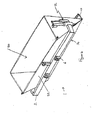
- a screed working apparatus 1 comprises frame 2 with a base portion 4 having connections 6 for attachment to a three point linkage of a vehicle, such as a tractor.
- a vehicle such as a tractor.
- Other suitable coupling arrangements are envisaged to allow the frame to be coupled to other vehicles.
- the frame 2 may be provided with quick coupling means to allow the apparatus to be quickly attached to and removed from the vehicle.
- the frame 2 supports a screeding means, in the form of a first elongate beam or screed 10 extending transverse to the normal direction of travel of the vehicle upon which the apparatus is mounted.
- the end portions 10a,10b of the screed be hinged to be foldable to reduce the width of the screed during transportation.
- the first elongate beam or screed 10 defining the screeding means is preferably provided with or connected to a vibration generating means (not shown in Figure 1 ) for vibrating the screed 10.
- the vibration generating means may comprise the motor and/or an eccentric rotor.
- the motor may be an electric motor or a hydraulic motor and may be powered from the vehicle or the vibration generating means may be driven via a mechanical power take provided on the vehicle upon which the apparatus is mounted.
- the motor of the vibration generating means may comprise a self contained internal combustion engine.
- the screed 10 is supported from the frame 2 via a pair of hydraulic rams 12 coupled to vertical guide posts 13 extending through guide tubes 14 mounted on the frame whereby the height of the screed 10 with respect to the frame 2 can be adjusted to vary the working height of the screed 10.
- the height of the screed 10 may be controlled by a height control means comprising a laser device for ensuring the screed 10 remains at a constant desired height required to correctly level a region of concrete.
- a height control means comprising a laser device for ensuring the screed 10 remains at a constant desired height required to correctly level a region of concrete.
- parallel timber guides or shuttering may be used to determine the height of the screed 10, the screed 10 resting on such guides during use, as is known In the art.
- a screed supporting portion of the frame 2 is mounted on the base portion 4 via a hydraulically controlled pivot mount 16 whereby the angle of the screed 10 with respect to the normal direction of travel of the vehicle upon which the apparatus is mounted can be adjusted, for example to remove excess material to one or other side of the apparatus 1.
- a raking means In the form of a second elongate beam or plate 20, is mounted on the frame ahead of the first elongate beam or screed 10 for removing excess material from a surface.
- the second elongate beam 20 of the raking means is preferably mounted at an angle to the screed 10 of the screeding means, such that the raking means can push excess material to one side of the apparatus.
- the second elongate beam 20 of the raking means may be mounted on the frame 2 such that the angle of the beam 20 with respect to the normal direction of travel of the vehicle up which the apparatus Is mounted is adjustable.
- a finishing beam 30 may be mounted behind the screed 10, extending parallel thereto.
- Figure 2 illustrates the location of a vibration generating means 11 on the screed 10.
- the first elongate beam or screed 10 and/or the second elongate beam 20 of the raking means may be detachably mounted upon the support frame 2 such that a number of different interchangeable beams and/or blades can be provided that can be selectively attached to the apparatus to allow the apparatus to work a number of different materials.
- one beam or screed may be provided for working concrete
- a second beam or screed may be provided for working tar (the second beam having optional heating means, such as burner nozzles, provided thereon)
- a third beam may be provided having a raking edge for raking and/or levelling soil.
- an auger 40 may be mounted on the beam 10 for conveying excess material to one or both sides of the beam.
- Such auger 25 may be used when It is desired to level a region of tarmac or similar particulate material.
- the auger may be powered by a motor, which may be the same motor used for vibrating the screed 10.
- the auger may be powered from a power take off of the vehicle upon which the apparatus 1 is mounted.
- a hopper 50 may be mounted on the apparatus 1 for delivering concrete onto a surface in front of the screed 10.
- the hopper 50 may be mounted directly on the screed 10 to deliver concrete at the leading edge of the screed 10.
- the hopper 50 may be provided with a hinged front wall 52 having a lower dispensing opening 54, whereby the dispensing opening 54 can be opened and closed and varied in width by adjusting the angular position of the front wall 52 of the hopper 50.
- rams 12 are provided for adjusting the height of the screed 10.
- the vibrations imparted to the screed 10 by the vibration generating means may also serve to encourage the dispensing of concrete through the dispensing opening 54 of the hopper 50.
- a concrete storage hopper or vessel may be mounted remove from the screed 10, either on the frame 2 of the apparatus or on the vehicle upon which the apparatus is mounted.
- Hoses and pumps may be provided for delivering concrete to the ground in front of the screed 10, preferably via one or more dispensing nozzles or slots.
- the apparatus may include an expansion joint creating means in the form of an elongate blade 60 having a lower cutting edge that can be pushed Into the concrete surface by means of suitable linear actuators, such as double acting hydraulic rams 62.
- the blade 60 may be adapted to detachably support a plastic or wooden footing thereon such that the footing can be inserted Into an expansion joint as the expansion joint is created by the blade 60.
- Releasable fastening means, such as clips, may be provided on the blade for temporarily securing the footing to the blade 60.
- the raking means is formed by an elongate dozer blade 70 to enable the raking means to remove excess material from the surface to be levelled.
- the dozer blade 70 may have a corrugated profile to provide greater strength and resistance to bending or folding of the blade.
- the respective beams and blades may rest upon timber guides to set the height of the blades or, alternatively, a height control mechanism may be provided, such as a laser device provided on at least one side of the screed 10 for determining the height of the screed 10. Similar height determining means may be associated with the screed 10 on the opposite side of the apparatus.
- a control means may be provided for controlling rams and/or the linkage between the vehicle and the apparatus to adjust the height of the screed 10 and/or the other beams or blades, where provided, based upon the height measurements obtained by the laser device.
- the apparatus 1 may be mounted on the three point linkage of a vehicle 6, such as a tractor, and can be drawn over an area of uncured concrete.
- the raking means 20,70 may remove excess concrete ahead of the screed 10.
- the vibrating screed 10 levels and consolidates the concrete.
- the finishing beam 30 smoothes the surface of the concrete.
- the working height of the raking means 20,70, screed 10 and finishing beam30 may be set by parallel guides upon which the respective beams rest.
- a height adjusting means may be provided on the frame and the height may be determined by a laser device for determining the height of the respective beams 10,20,30,70.
- Ground engaging rollers may be provided on the apparatus for forming a textured or patterned surface on the material over which the apparatus is traversed. Such rollers may be mounted on a finishing beam 30 or may be provided on a separate interchangeable beam adapted to be mounted in place of any existing finishing beam 30.
- an expansion joint can be created In the concrete by stopping the apparatus 1 and moving the elongate blade 60 into contact with and Into the concrete at a desired location.
Landscapes
- Engineering & Computer Science (AREA)
- Architecture (AREA)
- Civil Engineering (AREA)
- Structural Engineering (AREA)
- Road Paving Machines (AREA)
Applications Claiming Priority (1)
| Application Number | Priority Date | Filing Date | Title |
|---|---|---|---|
| GBGB0918761.8A GB0918761D0 (en) | 2009-10-27 | 2009-10-27 | Screed working apparatus |
Publications (2)
| Publication Number | Publication Date |
|---|---|
| EP2317009A2 true EP2317009A2 (fr) | 2011-05-04 |
| EP2317009A3 EP2317009A3 (fr) | 2012-12-12 |
Family
ID=41426728
Family Applications (1)
| Application Number | Title | Priority Date | Filing Date |
|---|---|---|---|
| EP10013964A Withdrawn EP2317009A3 (fr) | 2009-10-27 | 2010-10-26 | Appareil de travail de chape |
Country Status (3)
| Country | Link |
|---|---|
| US (1) | US20110097150A1 (fr) |
| EP (1) | EP2317009A3 (fr) |
| GB (1) | GB0918761D0 (fr) |
Families Citing this family (5)
| Publication number | Priority date | Publication date | Assignee | Title |
|---|---|---|---|---|
| US8621817B1 (en) * | 2010-12-03 | 2014-01-07 | Kenneth Robert Kreizinger | Vertical vibrating screed |
| US20140314482A1 (en) * | 2013-04-17 | 2014-10-23 | Rfvc Associates, Inc. | Forms and screed for paving materials |
| CN112080987B (zh) * | 2020-09-10 | 2021-09-14 | 嘉兴博睿创业服务有限公司 | 道路施工用碎石料双层连铺装置 |
| US12460359B2 (en) * | 2022-02-18 | 2025-11-04 | Greg Schut | Concrete finishing tool |
| CN117565176A (zh) * | 2023-12-08 | 2024-02-20 | 烟台正大城发检测有限公司 | 一种混凝土振动装置 |
Family Cites Families (10)
| Publication number | Priority date | Publication date | Assignee | Title |
|---|---|---|---|---|
| US1644511A (en) * | 1921-12-29 | 1927-10-04 | Edward G Carr | Concrete-road machine |
| US3098413A (en) * | 1960-05-09 | 1963-07-23 | Guntert & Zimmerman Const Div | Concrete pavement laying machine with grooving mechanism |
| DE1932951A1 (de) * | 1969-06-28 | 1971-01-07 | Dingler Werke Ag | Vorrichtung zum Verdichten und Glaetten einer auf eine Strassenoberflaeche aufgebrachten Schicht von Strassendeckmaterial |
| US4863310A (en) * | 1988-10-11 | 1989-09-05 | Jeffrey Reed | Paving apparatus |
| BE1009417A3 (nl) * | 1995-05-19 | 1997-03-04 | Alfa Ind | Machine voor het afstrijken van gestort beton. |
| US6089787A (en) * | 1998-05-26 | 2000-07-18 | Allen Engineering Corp. | Transformable two-person floating screed with automatic grade control |
| US6447204B1 (en) * | 2001-08-27 | 2002-09-10 | Mcdonald Lowell | Multiple implement screed |
| DE10226298C1 (de) * | 2002-06-07 | 2003-10-30 | Thomas Vogl | Anbaugerät für Rad- und Kompaktlader |
| US6981819B1 (en) * | 2004-01-14 | 2006-01-03 | Suckow Robert E | Tilting screed |
| US7559719B2 (en) * | 2007-05-09 | 2009-07-14 | Nasby Victor B | Screed attachment for skid steer vehicle |
-
2009
- 2009-10-27 GB GBGB0918761.8A patent/GB0918761D0/en not_active Ceased
-
2010
- 2010-10-26 EP EP10013964A patent/EP2317009A3/fr not_active Withdrawn
- 2010-10-26 US US12/912,239 patent/US20110097150A1/en not_active Abandoned
Non-Patent Citations (1)
| Title |
|---|
| None |
Also Published As
| Publication number | Publication date |
|---|---|
| EP2317009A3 (fr) | 2012-12-12 |
| GB0918761D0 (en) | 2009-12-09 |
| US20110097150A1 (en) | 2011-04-28 |
Similar Documents
| Publication | Publication Date | Title |
|---|---|---|
| US6183160B1 (en) | Screeding apparatus and method incorporating oscillating attachment | |
| US8038366B2 (en) | Wheeled concrete screeding device | |
| US9637872B1 (en) | Methods for paving a trail between obstacles | |
| US3936211A (en) | Drainage ditch mule | |
| US7311466B2 (en) | Apparatus and method for subgrade preparation | |
| US9382674B1 (en) | Concrete finishing machine | |
| US9010310B2 (en) | Independently supported concrete saw apparatus and method | |
| EP2317009A2 (fr) | Appareil de travail de chape | |
| US20030161684A1 (en) | Apparatus and method for subgrade preparation | |
| US4068970A (en) | Concrete finishing machines | |
| EP2154292A2 (fr) | Appareil de travail avec poutre lisseuse | |
| US6695531B1 (en) | Concrete slumping implement | |
| US4312602A (en) | Wet concrete pavement spreading machine and reinforcing rod layer | |
| US6715957B2 (en) | Paving apparatus with retractable pavement forming assembly | |
| US3224348A (en) | Vibrating screed | |
| US2034942A (en) | Vibrating finishing screed | |
| US8256986B2 (en) | Machine for paving concrete paths | |
| US4397580A (en) | Vibrating screed and curb/gutter forming apparatus and method | |
| CN214033277U (zh) | 三维激光摊铺整平机 | |
| JPH0724410Y2 (ja) | 半剛性舗装機 | |
| CN223118803U (zh) | 滑模摊铺机 | |
| US20230235529A1 (en) | Grader | |
| US2190562A (en) | Road building machine | |
| JPH0527523Y2 (fr) | ||
| GB2080868A (en) | Improvements in or relating to apparatus for moulding concrete mix |
Legal Events
| Date | Code | Title | Description |
|---|---|---|---|
| PUAI | Public reference made under article 153(3) epc to a published international application that has entered the european phase |
Free format text: ORIGINAL CODE: 0009012 |
|
| AK | Designated contracting states |
Kind code of ref document: A2 Designated state(s): AL AT BE BG CH CY CZ DE DK EE ES FI FR GB GR HR HU IE IS IT LI LT LU LV MC MK MT NL NO PL PT RO RS SE SI SK SM TR |
|
| AX | Request for extension of the european patent |
Extension state: BA ME |
|
| PUAL | Search report despatched |
Free format text: ORIGINAL CODE: 0009013 |
|
| AK | Designated contracting states |
Kind code of ref document: A3 Designated state(s): AL AT BE BG CH CY CZ DE DK EE ES FI FR GB GR HR HU IE IS IT LI LT LU LV MC MK MT NL NO PL PT RO RS SE SI SK SM TR |
|
| AX | Request for extension of the european patent |
Extension state: BA ME |
|
| 17P | Request for examination filed |
Effective date: 20120808 |
|
| 17Q | First examination report despatched |
Effective date: 20120829 |
|
| PUAF | Information related to the publication of a search report (a3 document) modified or deleted |
Free format text: ORIGINAL CODE: 0009199SEPU |
|
| PUAL | Search report despatched |
Free format text: ORIGINAL CODE: 0009013 |
|
| RIC1 | Information provided on ipc code assigned before grant |
Ipc: E01C 19/48 20060101ALI20121025BHEP Ipc: E01C 19/40 20060101ALI20121025BHEP Ipc: E01C 23/02 20060101ALI20121025BHEP Ipc: E01C 19/15 20060101AFI20121025BHEP |
|
| D17D | Deferred search report published (deleted) | ||
| AK | Designated contracting states |
Kind code of ref document: A3 Designated state(s): AL AT BE BG CH CY CZ DE DK EE ES FI FR GB GR HR HU IE IS IT LI LT LU LV MC MK MT NL NO PL PT RO RS SE SI SK SM TR |
|
| AX | Request for extension of the european patent |
Extension state: BA ME |
|
| STAA | Information on the status of an ep patent application or granted ep patent |
Free format text: STATUS: THE APPLICATION IS DEEMED TO BE WITHDRAWN |
|
| 18D | Application deemed to be withdrawn |
Effective date: 20130501 |