EP2317057A2 - Anschlag für eine verschiebbare Tür oder Fenster - Google Patents
Anschlag für eine verschiebbare Tür oder Fenster Download PDFInfo
- Publication number
- EP2317057A2 EP2317057A2 EP10009412A EP10009412A EP2317057A2 EP 2317057 A2 EP2317057 A2 EP 2317057A2 EP 10009412 A EP10009412 A EP 10009412A EP 10009412 A EP10009412 A EP 10009412A EP 2317057 A2 EP2317057 A2 EP 2317057A2
- Authority
- EP
- European Patent Office
- Prior art keywords
- stop
- profile
- recess
- window
- web
- Prior art date
- Legal status (The legal status is an assumption and is not a legal conclusion. Google has not performed a legal analysis and makes no representation as to the accuracy of the status listed.)
- Withdrawn
Links
Images

Classifications
-
- E—FIXED CONSTRUCTIONS
- E05—LOCKS; KEYS; WINDOW OR DOOR FITTINGS; SAFES
- E05F—DEVICES FOR MOVING WINGS INTO OPEN OR CLOSED POSITION; CHECKS FOR WINGS; WING FITTINGS NOT OTHERWISE PROVIDED FOR, CONCERNED WITH THE FUNCTIONING OF THE WING
- E05F5/00—Braking devices, e.g. checks; Stops; Buffers
- E05F5/003—Braking devices, e.g. checks; Stops; Buffers for sliding wings
-
- E—FIXED CONSTRUCTIONS
- E05—LOCKS; KEYS; WINDOW OR DOOR FITTINGS; SAFES
- E05D—HINGES OR SUSPENSION DEVICES FOR DOORS, WINDOWS OR WINGS
- E05D15/00—Suspension arrangements for wings
- E05D15/06—Suspension arrangements for wings for wings sliding horizontally more or less in their own plane
- E05D15/0621—Details, e.g. suspension or supporting guides
- E05D15/0626—Details, e.g. suspension or supporting guides for wings suspended at the top
- E05D15/0652—Tracks
-
- E—FIXED CONSTRUCTIONS
- E05—LOCKS; KEYS; WINDOW OR DOOR FITTINGS; SAFES
- E05Y—INDEXING SCHEME ASSOCIATED WITH SUBCLASSES E05D AND E05F, RELATING TO CONSTRUCTION ELEMENTS, ELECTRIC CONTROL, POWER SUPPLY, POWER SIGNAL OR TRANSMISSION, USER INTERFACES, MOUNTING OR COUPLING, DETAILS, ACCESSORIES, AUXILIARY OPERATIONS NOT OTHERWISE PROVIDED FOR, APPLICATION THEREOF
- E05Y2201/00—Constructional elements; Accessories therefor
- E05Y2201/20—Brakes; Disengaging means; Holders; Stops; Valves; Accessories therefor
- E05Y2201/224—Stops
-
- E—FIXED CONSTRUCTIONS
- E05—LOCKS; KEYS; WINDOW OR DOOR FITTINGS; SAFES
- E05Y—INDEXING SCHEME ASSOCIATED WITH SUBCLASSES E05D AND E05F, RELATING TO CONSTRUCTION ELEMENTS, ELECTRIC CONTROL, POWER SUPPLY, POWER SIGNAL OR TRANSMISSION, USER INTERFACES, MOUNTING OR COUPLING, DETAILS, ACCESSORIES, AUXILIARY OPERATIONS NOT OTHERWISE PROVIDED FOR, APPLICATION THEREOF
- E05Y2201/00—Constructional elements; Accessories therefor
- E05Y2201/60—Suspension or transmission members; Accessories therefor
- E05Y2201/622—Suspension or transmission members elements
- E05Y2201/684—Rails; Tracks
-
- E—FIXED CONSTRUCTIONS
- E05—LOCKS; KEYS; WINDOW OR DOOR FITTINGS; SAFES
- E05Y—INDEXING SCHEME ASSOCIATED WITH SUBCLASSES E05D AND E05F, RELATING TO CONSTRUCTION ELEMENTS, ELECTRIC CONTROL, POWER SUPPLY, POWER SIGNAL OR TRANSMISSION, USER INTERFACES, MOUNTING OR COUPLING, DETAILS, ACCESSORIES, AUXILIARY OPERATIONS NOT OTHERWISE PROVIDED FOR, APPLICATION THEREOF
- E05Y2600/00—Mounting or coupling arrangements for elements provided for in this subclass
- E05Y2600/50—Mounting methods; Positioning
- E05Y2600/502—Clamping
-
- E—FIXED CONSTRUCTIONS
- E05—LOCKS; KEYS; WINDOW OR DOOR FITTINGS; SAFES
- E05Y—INDEXING SCHEME ASSOCIATED WITH SUBCLASSES E05D AND E05F, RELATING TO CONSTRUCTION ELEMENTS, ELECTRIC CONTROL, POWER SUPPLY, POWER SIGNAL OR TRANSMISSION, USER INTERFACES, MOUNTING OR COUPLING, DETAILS, ACCESSORIES, AUXILIARY OPERATIONS NOT OTHERWISE PROVIDED FOR, APPLICATION THEREOF
- E05Y2600/00—Mounting or coupling arrangements for elements provided for in this subclass
- E05Y2600/60—Mounting or coupling members; Accessories therefor
-
- E—FIXED CONSTRUCTIONS
- E05—LOCKS; KEYS; WINDOW OR DOOR FITTINGS; SAFES
- E05Y—INDEXING SCHEME ASSOCIATED WITH SUBCLASSES E05D AND E05F, RELATING TO CONSTRUCTION ELEMENTS, ELECTRIC CONTROL, POWER SUPPLY, POWER SIGNAL OR TRANSMISSION, USER INTERFACES, MOUNTING OR COUPLING, DETAILS, ACCESSORIES, AUXILIARY OPERATIONS NOT OTHERWISE PROVIDED FOR, APPLICATION THEREOF
- E05Y2800/00—Details, accessories and auxiliary operations not otherwise provided for
- E05Y2800/26—Form or shape
- E05Y2800/27—Profiles; Strips
-
- E—FIXED CONSTRUCTIONS
- E05—LOCKS; KEYS; WINDOW OR DOOR FITTINGS; SAFES
- E05Y—INDEXING SCHEME ASSOCIATED WITH SUBCLASSES E05D AND E05F, RELATING TO CONSTRUCTION ELEMENTS, ELECTRIC CONTROL, POWER SUPPLY, POWER SIGNAL OR TRANSMISSION, USER INTERFACES, MOUNTING OR COUPLING, DETAILS, ACCESSORIES, AUXILIARY OPERATIONS NOT OTHERWISE PROVIDED FOR, APPLICATION THEREOF
- E05Y2800/00—Details, accessories and auxiliary operations not otherwise provided for
- E05Y2800/26—Form or shape
- E05Y2800/29—Form or shape forming a unitary piece with another element
-
- E—FIXED CONSTRUCTIONS
- E05—LOCKS; KEYS; WINDOW OR DOOR FITTINGS; SAFES
- E05Y—INDEXING SCHEME ASSOCIATED WITH SUBCLASSES E05D AND E05F, RELATING TO CONSTRUCTION ELEMENTS, ELECTRIC CONTROL, POWER SUPPLY, POWER SIGNAL OR TRANSMISSION, USER INTERFACES, MOUNTING OR COUPLING, DETAILS, ACCESSORIES, AUXILIARY OPERATIONS NOT OTHERWISE PROVIDED FOR, APPLICATION THEREOF
- E05Y2900/00—Application of doors, windows, wings or fittings thereof
- E05Y2900/10—Application of doors, windows, wings or fittings thereof for buildings or parts thereof
- E05Y2900/13—Type of wing
- E05Y2900/132—Doors
-
- E—FIXED CONSTRUCTIONS
- E05—LOCKS; KEYS; WINDOW OR DOOR FITTINGS; SAFES
- E05Y—INDEXING SCHEME ASSOCIATED WITH SUBCLASSES E05D AND E05F, RELATING TO CONSTRUCTION ELEMENTS, ELECTRIC CONTROL, POWER SUPPLY, POWER SIGNAL OR TRANSMISSION, USER INTERFACES, MOUNTING OR COUPLING, DETAILS, ACCESSORIES, AUXILIARY OPERATIONS NOT OTHERWISE PROVIDED FOR, APPLICATION THEREOF
- E05Y2900/00—Application of doors, windows, wings or fittings thereof
- E05Y2900/10—Application of doors, windows, wings or fittings thereof for buildings or parts thereof
- E05Y2900/13—Type of wing
- E05Y2900/148—Windows
Definitions
- the invention relates to a stop for a sliding door or window, which is arranged within a profile.
- Sliding doors or windows are usually performed in an upper and possibly lower profile.
- carriages or rollers are arranged, which receive the weight of the door or the window and move over a tread.
- the lower profile serves to ensure a guide of the door or the window, in particular a lifting of the upper profile should be avoided.
- a limitation of the displacement is done by stoppers or stops, which are arranged visibly. In this case, the visible arrangement of disadvantage, since this is sensitive to dirt, susceptible to manipulation and disturbing design.
- the invention provides that the stop is arranged within the profile and essentially comprises an upper part and a lower part, which comprise a web of the profile by clamping.
- an invisible stop is created, which is protected due to the arrangement in profile from moisture and dirt.
- movable shower doors where the stop is arranged in the lower profile, thus a cheap, protected against moisture and moisture solution is created, which is also tamper-proof.
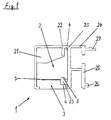
- FIG. 1 and 2 an embodiment of the stop 1 according to the invention is shown.
- a stop 1 is slidably disposed within a profile 20.
- the profile 20 is shown only as a small portion and extends along the direction of displacement X of the sliding door or window, not shown.
- the stop 1 consists essentially of two parts, namely an upper part 2 and a lower part 3, which comprise a web 23 within a profile 20 by clamping.
- the upper part 2 has a recess 5 which extends over the entire width of the upper part 2 in the displacement direction X.
- a recess 6 is arranged on the lower part 3, which also extends over the entire width of the lower part 3.
- the upper part 2 and the lower part 3 When mounting the stop 1, the upper part 2 and the lower part 3 by clamping the web 23, which thereby at least partially disposed in the room is, which is created by the recess 6 and recess 5.
- the clamping force is produced via a screw connection, which consists of at least one nut 10 and a screw 11.
- one or more holes 8 are arranged in the lower part 3, which are penetrated by the one or more screws 11.
- a gap 7 can be arranged at least partially between upper part 2 and lower part 3, with the manufacturing tolerances between web 23 and recess 5 / recess 6 can be compensated.
- a displacement of the stop 1 is achieved by the screw 10/11 is at least partially released and the clamp connection is released.
- the stopper 1 is then not tilted within the profile 20, a leg 4 is arranged on the stop 1, which is supported on a further web 22 within the profile 20.
- the leg 4 is arranged on the upper part 2 and extends a rear boundary wall, which bears against an inner surface of the profile 20.
- the profile 20 forms a U- or C-shaped guide space 21, within which a carriage. Rollers or other guide elements of the sliding door or window can be arranged.
- the open side of the guide space 21 is preferably arranged towards the bottom, so that moisture or dirt can not penetrate into the profile.
- the profile 20 may be arranged above or below the sliding door or window.
- the webs 22, 23 are arranged or formed so that they protrude into the guide space 21 of the profile 20 and thereby correspond to the stop 1.
- the screws 11 are accessible only from below, so that an adjustment of the stop, in particular in a lower profile of a sliding door or window only by means of an angled tool is possible, so that a tamper-proof arrangement is created.
- the profile 20 can be attached via further webs 24, 25 to a substructure or mounting plate, not shown, by means of latching, hook 26 or clip connection 27.
Landscapes
- Wing Frames And Configurations (AREA)
- Closing And Opening Devices For Wings, And Checks For Wings (AREA)
Abstract
Description
- Die Erfindung betrifft einen Anschlag für eine verschiebbare Tür oder Fenster, der innerhalb eines Profils angeordnet ist.
- Verschiebbare Türen oder Fenster werden üblicherweise in einem oberen und ggf. unteren Profil geführt. In dem oberen Profil werden Laufwagen oder Rollen angeordnet, die das Gewicht der Tür oder des Fensters aufnehmen und über eine Lauffläche bewegen. Das untere Profil dient dazu, eine Führung der Tür oder des Fensters zu gewährleisten, wobei insbesondere ein Ausheben aus dem oberen Profil vermieden werden soll. Eine Begrenzung des Verschiebeweges erfolgt durch Stopper oder Anschläge, die sichtbar angeordnet werden. Dabei ist die sichtbare Anordnung von Nachteil, da dies schmutzempfindlich ist, manipulationsanfällig und vom Design her störend.
- Es ist daher Aufgabe der vorliegenden Erfindung, einen Anschlag für eine verschiebbare Tür oder Fenster zu schaffen, der verdeckt und manipulationssicher angeordnet ist und vor Nässe und Schmutz geschützt ist.
- Zur Lösung dieser Aufgabe wird ein Anschlag mit den Merkmalen des Anspruchs 1 vorgeschlagen. Weitere mögliche Ausführungsbeispiele sind in den abhängigen Ansprüchen angegeben.
- Dazu ist erfindungsgemäß vorgesehen, dass der Anschlag innerhalb des Profils angeordnet ist und im Wesentlichen ein Oberteil und ein Unterteil umfasst, die einen Steg des Profils klemmend umfassen. Damit wird ein unsichtbarer Anschlag geschaffen, der aufgrund der Anordnung im Profil vor Feuchtigkeit und Schmutz geschützt ist. Insbesondere bei verschiebbaren Duschtüren, bei denen der Anschlag im unteren Profil angeordnet ist, wird damit eine preiswerte, vor Feuchtigkeit und Nässe geschützte Lösung geschaffen, die auch noch manipulationssicher ist.
- Weitere Vorteile, Merkmale und Einzelheiten der Erfindung ergeben sich aus der nachfolgenden Beschreibung, in der unter Bezugnahme auf die Zeichnungen ein Ausführungsbeispiel der Erfindung im Einzelnen beschrieben ist. Dabei können die in den Ansprüchen und in der Beschreibung erwähnten Merkmale jeweils einzeln für sich oder in beliebiger Kombination erfindungswesentlich sein.
- Es zeigen:
- Figur 1
- einen Querschnitt durch ein Profil mit einem eingebauten Anschlag,
- Figur 2
- eine perspektivische Darstellung des demontierten An- schlages in dem Profil.
- In
Figur 1 und2 ist ein Ausführungsbeispiel des erfindungsgemäßen Anschlages 1 dargestellt. Ein Anschlag 1 ist innerhalb eines Profiles 20 verschiebbar angeordnet. Das Profil 20 ist dabei nur als kleiner Abschnitt dargestellt und erstreckt sich entlang der Verschieberichtung X der nicht dargestellten verschiebbaren Tür oder Fenster. Der Anschlag 1 besteht im Wesentlichen aus zwei Teilen, nämlich einem Oberteil 2 und einem Unterteil 3, die einen Steg 23 innerhalb eines Profils 20 klemmend umfassen. Hierzu weist das Oberteil 2 eine Vertiefung 5 auf, die sich in Verschieberichtung X über die gesamte Breite des Oberteiles 2 erstreckt. Korrespondierend dazu ist am Unterteil 3 eine Ausnehmung 6 angeordnet, die sich ebenfalls über die gesamte Breite des Unterteiles 3 erstreckt. Beim Montieren des Anschlages 1 umfassen das Oberteil 2 und das Unterteil 3 klemmend den Steg 23, der dabei zumindest teilweise in dem Raum angeordnet ist, der durch die Ausnehmung 6 und Vertiefung 5 geschaffen wird. Die Klemmkraft wird dabei über eine Schraubverbindung hergestellt, die aus mindestens einer Mutter 10 und einer Schraube 11 besteht. Hierzu sind im Unterteil 3 eine oder mehrere Bohrungen 8 angeordnet, die von der oder den Schrauben 11 durchdrungen werden. Im Oberteil 2 befinden sich formschlüssige Aufnahmen 9 für die Mutter 10, die in diesem Ausführungsbeispiel als Sechskant ausgeführt ist. Um eine sichere Klemmwirkung zu erzielen, kann zumindest teilweise zwischen Oberteil 2 und Unterteil 3 ein Spalt 7 angeordnet werden, mit dem Fertigungstoleranzen zwischen Steg 23 und Vertiefung 5/Ausnehmung 6 ausgeglichen werden können. Ein Verschieben des Anschlages 1 wird erreicht, indem die Schraubverbindung 10/11 zumindest teilweise gelöst wird und die Klemmverbindung aufgehoben wird. Damit der Anschlag 1 dann nicht innerhalb des Profiles 20 verkantet, ist am Anschlag 1 ein Schenkel 4 angeordnet, der sich an einem weiteren Steg 22 innerhalb des Profils 20 abstützt. In diesem Ausführungsbeispiel ist der Schenkel 4 am Oberteil 2 angeordnet und verlängert eine rückseitige Begrenzungswand, die an einer Innenfläche des Profils 20 anliegt. - Das Profil 20 bildet einen U- oder C-förmigen Führungsraum 21, innerhalb dessen ein Laufwagen. Rollen oder andere Führungselemente der verschiebbaren Tür oder Fenster angeordnet sein können. Die offene Seite des Führungsraumes 21 ist dabei bevorzugt Richtung Boden angeordnet, damit Feuchtigkeit oder Schmutz nicht in das Profil eindringen kann. Dabei kann das Profil 20 oberhalb oder unterhalb der verschiebbaren Tür oder Fenster angeordnet sein. Die Stege 22, 23 sind dabei so angeordnet oder ausgebildet, dass sie in den Führungsraum 21 des Profils 20 hineinragen und dabei mit dem Anschlag 1 korrespondieren. Durch den nach unten offenen Führungsraum 21 sind die Schrauben 11 nur von unten zugänglich, so dass eine Verstellung des Anschlages insbesondere in einem unteren Profil einer verschiebbaren Tür oder Fenster nur mittels eines abgewinkelten Werkzeuges möglich ist, so dass eine manipulationssichere Anordnung geschaffen wird. Das Profil 20 kann über weitere Stege 24, 25 an einer nicht dargestellten Unterkonstruktion oder Montageplatte mittels Rast-, Haken- 26 oder Clipverbindung 27 befestigt werden.
-
- 1
- Anschlag
- 2
- Oberteil
- 3
- Unterteil
- 4
- Schenkel
- 5
- Vertiefung
- 6
- Ausnehmung
- 7
- Spalt
- 8
- Bohrung
- 9
- Aufnahme
- 10
- Mutter
- 11
- Schraube
- 20
- Profil
- 21
- Führungsraum
- 22
- Steg
- 23
- Steg
- 24
- Steg
- 25
- Steg
- 26
- Hakenverbindung
- 27
- Clipverbindung
- X
- Verschiebebereich
Claims (7)
- Anschlag (1) für eine verschiebbare Tür oder Fenster, der innerhalb eines Profils (20) angeordnet ist und im Wesentlichen ein Oberteil (2) und ein Unterteil (3) umfasst, dadurch gekennzeichnet, dass das Oberteil (2) und das Unterteil (3) einen Steg (23) des Profils (20) klemmend umfassen.
- Anschlag (1) nach Anspruch 1, dadurch gekennzeichnet, dass das Oberteil (2) eine Vertiefung (5) und das Unterteil (3) eine Ausnehmung (6) aufweist, wobei die Vertiefung (5) und die Ausnehmung (6) einen Raum zur zumindest teilweise Aufnahme des Steges (23) schaffen.
- Anschlag (1) nach Anspruch 1 oder 2, dadurch gekennzeichnet, dass zwischen dem Oberteil (2) und dem Unterteil (3) ein Spalt (7) angeordnet ist.
- Anschlag (1) nach Anspruch 1, dadurch gekennzeichnet, dass das Oberteil (2) und das Unterteil (3) mittels einer Schraubverbindung miteinander verbunden sind.
- Anschlag (1) nach Anspruch 1, dadurch gekennzeichnet, dass der Anschlag (1) einen Schenkel (4) aufweist, der mit einem weiteren Steg (22) innerhalb des Profils (20) korrespondiert.
- Anschlag (1) nach Anspruch 5, dadurch gekennzeichnet, das der Schenkel (4) derart am Oberteil (2) angeordnet ist, dass eine Begrenzungswand des Oberteiles (2), die an einer Innenfläche des Profils (20) anliegt, verlängert wird.
- Anschlag (1) nach Anspruch 1 bis 6 zur Verwendung in einem Profil (20), welches einen U- oder C-förmigen Führungsraum (21) aufweist, wobei die Stege (22, 23) innerhalb des Führungsraumes (21) angeordnet sind.
Applications Claiming Priority (1)
| Application Number | Priority Date | Filing Date | Title |
|---|---|---|---|
| DE200920014566 DE202009014566U1 (de) | 2009-10-28 | 2009-10-28 | Anschlag für eine verschiebbare Tür oder Fenster |
Publications (2)
| Publication Number | Publication Date |
|---|---|
| EP2317057A2 true EP2317057A2 (de) | 2011-05-04 |
| EP2317057A3 EP2317057A3 (de) | 2014-04-23 |
Family
ID=41567098
Family Applications (1)
| Application Number | Title | Priority Date | Filing Date |
|---|---|---|---|
| EP10009412.7A Withdrawn EP2317057A3 (de) | 2009-10-28 | 2010-09-10 | Anschlag für eine verschiebbare Tür oder Fenster |
Country Status (2)
| Country | Link |
|---|---|
| EP (1) | EP2317057A3 (de) |
| DE (1) | DE202009014566U1 (de) |
Cited By (1)
| Publication number | Priority date | Publication date | Assignee | Title |
|---|---|---|---|---|
| EP3126602B1 (de) * | 2014-04-01 | 2025-04-23 | Bortoluzzi Sistemi S.p.A. | Widerlagerelement für dämpfer von schiebetüren |
Citations (1)
| Publication number | Priority date | Publication date | Assignee | Title |
|---|---|---|---|---|
| EP0626495A1 (de) * | 1993-03-26 | 1994-11-30 | Klein Iberica, S.A. | Mechanismus für Glasschiebetüren |
Family Cites Families (3)
| Publication number | Priority date | Publication date | Assignee | Title |
|---|---|---|---|---|
| US3490802A (en) * | 1967-04-06 | 1970-01-20 | Harry Zeit | Lock for sliding door |
| DE59703816C5 (de) * | 1996-09-18 | 2012-11-22 | Hörmann KG Antriebstechnik | Begrenzungsanschlag einer c-förmigen führungsprofilschiene für motorisch angetriebene gegenstände |
| DE202005013417U1 (de) * | 2005-08-19 | 2006-12-28 | Krimmel, Maria | Tragvorrichtung für Schiebetüren und damit verbundene Schiebetür |
-
2009
- 2009-10-28 DE DE200920014566 patent/DE202009014566U1/de not_active Expired - Lifetime
-
2010
- 2010-09-10 EP EP10009412.7A patent/EP2317057A3/de not_active Withdrawn
Patent Citations (1)
| Publication number | Priority date | Publication date | Assignee | Title |
|---|---|---|---|---|
| EP0626495A1 (de) * | 1993-03-26 | 1994-11-30 | Klein Iberica, S.A. | Mechanismus für Glasschiebetüren |
Cited By (1)
| Publication number | Priority date | Publication date | Assignee | Title |
|---|---|---|---|---|
| EP3126602B1 (de) * | 2014-04-01 | 2025-04-23 | Bortoluzzi Sistemi S.p.A. | Widerlagerelement für dämpfer von schiebetüren |
Also Published As
| Publication number | Publication date |
|---|---|
| EP2317057A3 (de) | 2014-04-23 |
| DE202009014566U1 (de) | 2010-01-21 |
Similar Documents
| Publication | Publication Date | Title |
|---|---|---|
| EP3452680B1 (de) | Dichtungsvorrichtung | |
| EP3862525B1 (de) | Nullschwelle für hebe-schiebe-tür | |
| EP2366857B1 (de) | Befestigungsanordnung für eine Schiebetür | |
| EP3208403B1 (de) | Haltevorrichtung für ein vordach und vordachanordnung | |
| EP2080862B1 (de) | Klemmbeschlag | |
| EP2792830A2 (de) | Halteelement zur Halterung eines Beschlagteils | |
| EP2113624A2 (de) | Tür- oder Fenstersicherungsvorrichtung | |
| AT507493A2 (de) | Laufrolle für einen schiebeflügel | |
| EP2317057A2 (de) | Anschlag für eine verschiebbare Tür oder Fenster | |
| EP3816383B1 (de) | Schiebetüranordnung | |
| EP2132391B1 (de) | Treibstangenanordnung mit mindestens einer treibstange und mindestens einem treibstangenführungselement | |
| EP2740873A2 (de) | Zur verdeckten Anordnung vorgesehenes Ecklager und Fenster mit einem Ecklager | |
| EP3771793B1 (de) | Beschlag für eine schiebetür | |
| EP1863999B1 (de) | Flügel einer tür oder eines fensters | |
| EP0940543B1 (de) | Schiebetüren-Rollenbeschlag | |
| DE102008006800A1 (de) | Führungsvorrichtung für einen Schiebeflügel | |
| DE102010060672A1 (de) | Fenster- oder Türrahmen | |
| DE29600891U1 (de) | Sicherungseinrichtung | |
| DE10323695B4 (de) | Schiebetürprofil | |
| DE20002285U1 (de) | Laufschiene für eine Glasschiebetür-Anordnung | |
| EP2586928B1 (de) | Plattenhalter insbesondere für Glastafeln | |
| DE102014202797B3 (de) | Distanzhalter | |
| EP2787160B1 (de) | Dichtung für einen Riegel und Dichtungsanordnung mit einer solchen Dichtung | |
| DE102011010832A1 (de) | Befestigung für Sonnenkollektoren | |
| EP1001123B1 (de) | Tür- oder Fensterband |
Legal Events
| Date | Code | Title | Description |
|---|---|---|---|
| PUAI | Public reference made under article 153(3) epc to a published international application that has entered the european phase |
Free format text: ORIGINAL CODE: 0009012 |
|
| AK | Designated contracting states |
Kind code of ref document: A2 Designated state(s): AL AT BE BG CH CY CZ DE DK EE ES FI FR GB GR HR HU IE IS IT LI LT LU LV MC MK MT NL NO PL PT RO SE SI SK SM TR |
|
| AX | Request for extension of the european patent |
Extension state: BA ME RS |
|
| PUAL | Search report despatched |
Free format text: ORIGINAL CODE: 0009013 |
|
| AK | Designated contracting states |
Kind code of ref document: A3 Designated state(s): AL AT BE BG CH CY CZ DE DK EE ES FI FR GB GR HR HU IE IS IT LI LT LU LV MC MK MT NL NO PL PT RO SE SI SK SM TR |
|
| AX | Request for extension of the european patent |
Extension state: BA ME RS |
|
| RIC1 | Information provided on ipc code assigned before grant |
Ipc: E05D 15/06 20060101ALI20140314BHEP Ipc: E05F 5/00 20060101AFI20140314BHEP |
|
| 17P | Request for examination filed |
Effective date: 20141023 |
|
| RBV | Designated contracting states (corrected) |
Designated state(s): AL AT BE BG CH CY CZ DE DK EE ES FI FR GB GR HR HU IE IS IT LI LT LU LV MC MK MT NL NO PL PT RO SE SI SK SM TR |
|
| RAP1 | Party data changed (applicant data changed or rights of an application transferred) |
Owner name: DORMA DEUTSCHLAND GMBH |
|
| STAA | Information on the status of an ep patent application or granted ep patent |
Free format text: STATUS: EXAMINATION IS IN PROGRESS |
|
| 17Q | First examination report despatched |
Effective date: 20161206 |
|
| RAP1 | Party data changed (applicant data changed or rights of an application transferred) |
Owner name: DORMAKABA DEUTSCHLAND GMBH |
|
| GRAP | Despatch of communication of intention to grant a patent |
Free format text: ORIGINAL CODE: EPIDOSNIGR1 |
|
| STAA | Information on the status of an ep patent application or granted ep patent |
Free format text: STATUS: GRANT OF PATENT IS INTENDED |
|
| INTG | Intention to grant announced |
Effective date: 20200513 |
|
| GRAS | Grant fee paid |
Free format text: ORIGINAL CODE: EPIDOSNIGR3 |
|
| STAA | Information on the status of an ep patent application or granted ep patent |
Free format text: STATUS: THE APPLICATION IS DEEMED TO BE WITHDRAWN |
|
| 18D | Application deemed to be withdrawn |
Effective date: 20200924 |