EP2317111B1 - Mischvorrichtung für ein Niederdruck-AGR-System einer Brennkraftmaschine - Google Patents
Mischvorrichtung für ein Niederdruck-AGR-System einer Brennkraftmaschine Download PDFInfo
- Publication number
- EP2317111B1 EP2317111B1 EP10189227A EP10189227A EP2317111B1 EP 2317111 B1 EP2317111 B1 EP 2317111B1 EP 10189227 A EP10189227 A EP 10189227A EP 10189227 A EP10189227 A EP 10189227A EP 2317111 B1 EP2317111 B1 EP 2317111B1
- Authority
- EP
- European Patent Office
- Prior art keywords
- butterfly valve
- mixing device
- inlet conduit
- shaft
- conduit
- Prior art date
- Legal status (The legal status is an assumption and is not a legal conclusion. Google has not performed a legal analysis and makes no representation as to the accuracy of the status listed.)
- Not-in-force
Links
- 238000002485 combustion reaction Methods 0.000 title claims abstract description 17
- 239000007789 gas Substances 0.000 claims description 29
- 238000001816 cooling Methods 0.000 claims description 11
- 230000033001 locomotion Effects 0.000 claims description 10
- 239000011810 insulating material Substances 0.000 claims description 9
- 230000000694 effects Effects 0.000 claims description 3
- 239000011819 refractory material Substances 0.000 claims description 3
- -1 and in particular Substances 0.000 claims 1
- 230000005540 biological transmission Effects 0.000 description 16
- 238000013021 overheating Methods 0.000 description 3
- 230000007935 neutral effect Effects 0.000 description 2
- 239000000126 substance Substances 0.000 description 2
- 238000011144 upstream manufacturing Methods 0.000 description 2
- 230000001154 acute effect Effects 0.000 description 1
- 239000000919 ceramic Substances 0.000 description 1
- 238000009413 insulation Methods 0.000 description 1
- 230000007257 malfunction Effects 0.000 description 1
- 230000004048 modification Effects 0.000 description 1
- 238000012986 modification Methods 0.000 description 1
- 230000005855 radiation Effects 0.000 description 1
- 230000003134 recirculating effect Effects 0.000 description 1
- 238000000926 separation method Methods 0.000 description 1
- 230000003584 silencer Effects 0.000 description 1
Images




Classifications
-
- F—MECHANICAL ENGINEERING; LIGHTING; HEATING; WEAPONS; BLASTING
- F02—COMBUSTION ENGINES; HOT-GAS OR COMBUSTION-PRODUCT ENGINE PLANTS
- F02M—SUPPLYING COMBUSTION ENGINES IN GENERAL WITH COMBUSTIBLE MIXTURES OR CONSTITUENTS THEREOF
- F02M26/00—Engine-pertinent apparatus for adding exhaust gases to combustion-air, main fuel or fuel-air mixture, e.g. by exhaust gas recirculation [EGR] systems
- F02M26/65—Constructional details of EGR valves
- F02M26/74—Protection from damage, e.g. shielding means
-
- F—MECHANICAL ENGINEERING; LIGHTING; HEATING; WEAPONS; BLASTING
- F02—COMBUSTION ENGINES; HOT-GAS OR COMBUSTION-PRODUCT ENGINE PLANTS
- F02M—SUPPLYING COMBUSTION ENGINES IN GENERAL WITH COMBUSTIBLE MIXTURES OR CONSTITUENTS THEREOF
- F02M26/00—Engine-pertinent apparatus for adding exhaust gases to combustion-air, main fuel or fuel-air mixture, e.g. by exhaust gas recirculation [EGR] systems
- F02M26/02—EGR systems specially adapted for supercharged engines
- F02M26/04—EGR systems specially adapted for supercharged engines with a single turbocharger
- F02M26/06—Low pressure loops, i.e. wherein recirculated exhaust gas is taken out from the exhaust downstream of the turbocharger turbine and reintroduced into the intake system upstream of the compressor
-
- F—MECHANICAL ENGINEERING; LIGHTING; HEATING; WEAPONS; BLASTING
- F02—COMBUSTION ENGINES; HOT-GAS OR COMBUSTION-PRODUCT ENGINE PLANTS
- F02M—SUPPLYING COMBUSTION ENGINES IN GENERAL WITH COMBUSTIBLE MIXTURES OR CONSTITUENTS THEREOF
- F02M26/00—Engine-pertinent apparatus for adding exhaust gases to combustion-air, main fuel or fuel-air mixture, e.g. by exhaust gas recirculation [EGR] systems
- F02M26/13—Arrangement or layout of EGR passages, e.g. in relation to specific engine parts or for incorporation of accessories
- F02M26/17—Arrangement or layout of EGR passages, e.g. in relation to specific engine parts or for incorporation of accessories in relation to the intake system
- F02M26/21—Arrangement or layout of EGR passages, e.g. in relation to specific engine parts or for incorporation of accessories in relation to the intake system with EGR valves located at or near the connection to the intake system
-
- F—MECHANICAL ENGINEERING; LIGHTING; HEATING; WEAPONS; BLASTING
- F02—COMBUSTION ENGINES; HOT-GAS OR COMBUSTION-PRODUCT ENGINE PLANTS
- F02M—SUPPLYING COMBUSTION ENGINES IN GENERAL WITH COMBUSTIBLE MIXTURES OR CONSTITUENTS THEREOF
- F02M26/00—Engine-pertinent apparatus for adding exhaust gases to combustion-air, main fuel or fuel-air mixture, e.g. by exhaust gas recirculation [EGR] systems
- F02M26/52—Systems for actuating EGR valves
- F02M26/64—Systems for actuating EGR valves the EGR valve being operated together with an intake air throttle
-
- F—MECHANICAL ENGINEERING; LIGHTING; HEATING; WEAPONS; BLASTING
- F02—COMBUSTION ENGINES; HOT-GAS OR COMBUSTION-PRODUCT ENGINE PLANTS
- F02M—SUPPLYING COMBUSTION ENGINES IN GENERAL WITH COMBUSTIBLE MIXTURES OR CONSTITUENTS THEREOF
- F02M26/00—Engine-pertinent apparatus for adding exhaust gases to combustion-air, main fuel or fuel-air mixture, e.g. by exhaust gas recirculation [EGR] systems
- F02M26/65—Constructional details of EGR valves
- F02M26/70—Flap valves; Rotary valves; Sliding valves; Resilient valves
-
- F—MECHANICAL ENGINEERING; LIGHTING; HEATING; WEAPONS; BLASTING
- F02—COMBUSTION ENGINES; HOT-GAS OR COMBUSTION-PRODUCT ENGINE PLANTS
- F02M—SUPPLYING COMBUSTION ENGINES IN GENERAL WITH COMBUSTIBLE MIXTURES OR CONSTITUENTS THEREOF
- F02M26/00—Engine-pertinent apparatus for adding exhaust gases to combustion-air, main fuel or fuel-air mixture, e.g. by exhaust gas recirculation [EGR] systems
- F02M26/65—Constructional details of EGR valves
- F02M26/72—Housings
- F02M26/73—Housings with means for heating or cooling the EGR valve
-
- F—MECHANICAL ENGINEERING; LIGHTING; HEATING; WEAPONS; BLASTING
- F02—COMBUSTION ENGINES; HOT-GAS OR COMBUSTION-PRODUCT ENGINE PLANTS
- F02M—SUPPLYING COMBUSTION ENGINES IN GENERAL WITH COMBUSTIBLE MIXTURES OR CONSTITUENTS THEREOF
- F02M26/00—Engine-pertinent apparatus for adding exhaust gases to combustion-air, main fuel or fuel-air mixture, e.g. by exhaust gas recirculation [EGR] systems
- F02M26/02—EGR systems specially adapted for supercharged engines
- F02M26/09—Constructional details, e.g. structural combinations of EGR systems and supercharger systems; Arrangement of the EGR and supercharger systems with respect to the engine
- F02M26/10—Constructional details, e.g. structural combinations of EGR systems and supercharger systems; Arrangement of the EGR and supercharger systems with respect to the engine having means to increase the pressure difference between the exhaust and intake system, e.g. venturis, variable geometry turbines, check valves using pressure pulsations or throttles in the air intake or exhaust system
-
- F—MECHANICAL ENGINEERING; LIGHTING; HEATING; WEAPONS; BLASTING
- F02—COMBUSTION ENGINES; HOT-GAS OR COMBUSTION-PRODUCT ENGINE PLANTS
- F02M—SUPPLYING COMBUSTION ENGINES IN GENERAL WITH COMBUSTIBLE MIXTURES OR CONSTITUENTS THEREOF
- F02M26/00—Engine-pertinent apparatus for adding exhaust gases to combustion-air, main fuel or fuel-air mixture, e.g. by exhaust gas recirculation [EGR] systems
- F02M26/13—Arrangement or layout of EGR passages, e.g. in relation to specific engine parts or for incorporation of accessories
- F02M26/14—Arrangement or layout of EGR passages, e.g. in relation to specific engine parts or for incorporation of accessories in relation to the exhaust system
- F02M26/15—Arrangement or layout of EGR passages, e.g. in relation to specific engine parts or for incorporation of accessories in relation to the exhaust system in relation to engine exhaust purifying apparatus
-
- F—MECHANICAL ENGINEERING; LIGHTING; HEATING; WEAPONS; BLASTING
- F02—COMBUSTION ENGINES; HOT-GAS OR COMBUSTION-PRODUCT ENGINE PLANTS
- F02M—SUPPLYING COMBUSTION ENGINES IN GENERAL WITH COMBUSTIBLE MIXTURES OR CONSTITUENTS THEREOF
- F02M26/00—Engine-pertinent apparatus for adding exhaust gases to combustion-air, main fuel or fuel-air mixture, e.g. by exhaust gas recirculation [EGR] systems
- F02M26/13—Arrangement or layout of EGR passages, e.g. in relation to specific engine parts or for incorporation of accessories
- F02M26/22—Arrangement or layout of EGR passages, e.g. in relation to specific engine parts or for incorporation of accessories with coolers in the recirculation passage
- F02M26/29—Constructional details of the coolers, e.g. pipes, plates, ribs, insulation or materials
- F02M26/31—Air-cooled heat exchangers
-
- F—MECHANICAL ENGINEERING; LIGHTING; HEATING; WEAPONS; BLASTING
- F02—COMBUSTION ENGINES; HOT-GAS OR COMBUSTION-PRODUCT ENGINE PLANTS
- F02M—SUPPLYING COMBUSTION ENGINES IN GENERAL WITH COMBUSTIBLE MIXTURES OR CONSTITUENTS THEREOF
- F02M26/00—Engine-pertinent apparatus for adding exhaust gases to combustion-air, main fuel or fuel-air mixture, e.g. by exhaust gas recirculation [EGR] systems
- F02M26/52—Systems for actuating EGR valves
- F02M26/53—Systems for actuating EGR valves using electric actuators, e.g. solenoids
- F02M26/54—Rotary actuators, e.g. step motors
Definitions
- the present invention relates to a mixing device for a low pressure EGR system of an internal combustion engine.
- EGR exhaust Gas Recirculation
- system feeds part of the exhaust gases produced by the combustion into the intake conduit so as to mix the exhaust gases with the fresh air in order to uniform the temperature in each combustion chamber, and consequently reduce the polluting substances present in the exhaust gases which are released into the atmosphere.
- An EGR system comprises an EGR conduit, which connects the exhaust conduit to the intake conduit, and a mixing device which is arranged at the intersection between the EGR conduit and the intake conduit, and which has the function of adjusting the mixing of exhaust gas from the exhaust conduit with the fresh air present in the intake conduit.
- the mixing device comprises a butterfly valve, which is arranged at the EGR conduit, is actuated by an electrical motor and has the function of varying the section of the EGR conduit to vary the flow of exhaust gases which are introduced into the intake conduit.
- the above-described structure of the mixing device has the advantage of being cost-effective and at the same of allowing to rather accurately adjust the exhaust gas flow rate introduced into the intake conduit; however, the above-described structure of the mixing device does not allow to accurately adjust the exhaust gas flow rate introduced into the intake conduit in all operative conditions, and in particular when the introduction of a particularly high exhaust gas flow rate into the intake conduit is required. Furthermore, the known mixing devices have problems of reliability over time, because the electrical motor may be subjected to excessive overheating caused by the heat coming from the EGR conduit, which in turn is heated by the exhaust gases which flow through the EGR conduit itself, and which indicatively have a temperature of at least 350-400°C.
- US2005145229A1 describes a mixing device for a low pressure EGR system of an internal combustion engine as described in the preamble of independent claim 1.
- a mixing device for a low pressure EGR system of an internal combustion engine is provided as disclosed in the appended claims.
- numeral 1 indicates as a whole an internal combustion engine supercharged by a turbocharger supercharging system 2.
- the internal combustion engine 1 comprises four cylinders 3, each of which is connected to an intake manifold 4 by means of at least one respective intake valve (not shown) and to an exhaust manifold 5 by means of at least one respective exhaust valve (not shown).
- the intake manifold 4 receives fresh air (i.e. air coming from the external environment) through an intake conduit 6, which is provided with an air cleaner 7 and is adjusted by a butterfly valve 8.
- An intercooler 9 for cooling the intake air is arranged along the intake conduit 6.
- An exhaust conduit 10, which feeds the exhaust gases produced by the combustion to an exhaust system, is connected to the exhaust manifold 5, which exhaust system emits the gases produced by the combustion into the atmosphere and normally comprises at least one catalyzer 11 and at least one silencer (not shown) arranged downstream of the catalyzer 11.
- the supercharging system 2 of the internal combustion engine 1 comprises a turbocharger 12 provided with a turbine 13, which is arranged along the exhaust conduit 10 for rotating at high speed under the bias of the exhaust gases expelled from the cylinders 3, and a turbocharger 14, which is arranged along the intake conduit 6 and is mechanically connected to the turbine 13 in order to be rotatably fed by the turbine 13 itself so as to increase the pressure of the air fed into the intake conduit 6.
- a bypass conduit 15 is provided along the exhaust conduit 10, which bypass conduit is connected in parallel to the turbine 13 so that the ends thereof are connected upstream and downstream of the turbine 13 itself; a wastegate 16 is arranged along the bypass conduit 15, which wastegate is adapted to adjust the exhaust gas flow rate through the bypass conduit 15 and is controlled by a pneumatic actuator 17.
- a bypass conduit 18 is provided along the intake conduit 6, which bypass conduit is connected in parallel to the turbocharger 14 so that the ends thereof are connected upstream and downstream of the turbocharger 14 itself; a Poff valve 19 is arranged along the bypass conduit 18, which Poff valve is adapted to adjust the exhaust gases which flow through the bypass conduit 18 and is controlled by an electrical actuator 20.
- the internal combustion engine 1 comprises a low pressure EGR system 21, which recalculates part of the exhaust gas present in the exhaust conduit 10 by reintroducing such exhaust gases into the intake conduit 6.
- An EGR system 21 comprises an EGR conduit 22, which connects the exhaust conduit 10 to the intake conduit 6, and a three-way mixing device 23, which is arranged at the intersection between the exhaust conduit 10 and the intake conduit 6, and which has the function of adjusting the mixing of the exhaust gases from the exhaust conduit 10 with the fresh air present in the intake conduit 6.
- a heat exchanger 24 is arranged along the EGR conduit 22 for cooling the exhaust gases from the exhaust conduit 10.
- Such a configuration is also named “Long-Route" EGR, because the EGR conduit 22 must be longer than normal to reach downstream of the catalyzer 11.
- the three-way mixing device 23 connects the intake manifold 6 to the EGR conduit 22.
- the mixing device 23 comprises an inlet conduit 25, which is connected in series to the EGR conduit 22, an inlet conduit 26, which is connected in series to a conduit coming from the air cleaner 7, and an outlet conduit 27, which is connected in series to the intake conduit 6.
- the inlet conduit 25 forms a square angle with the outlet conduit 27 and forms an obtuse angle with the inlet conduit 26, and the inlet conduit 26 forms an acute angle with the outlet conduit 27.
- the main valve 28 comprises a butterfly cap 30 and a shaft 31, which supports the butterfly cap 30 and is rotationally mounted.
- the secondary butterfly valve 28 comprises a butterfly cap 32 and a shaft 33, which supports the butterfly cap 32 and is rotationally mounted.
- the mixing device 23 comprises a common actuating device 34 which controls both the main butterfly valve 28 and the secondary butterfly valve 29.
- the common actuating device 34 comprises a single common electrical motor 35, which impresses motion to both butterfly valves 28 and 29, and a connecting element 36, which establishes a mechanical connection between the secondary butterfly valve 29 and the main butterfly valve 28 so that the reciprocal positions between the two butterfly valves 28 and 29 are mechanically linked to one another.
- the common electrical motor 35 transmits motion to the main butterfly valve 28 and thus directly controls the position of the main butterfly valve 28 itself; in turn, the main butterfly valve 28 transmits motion to the secondary butterfly valve 29 by means of the connection element 36, which links the position of the main butterfly valve 28 to the position of the secondary butterfly valve 29.
- the main butterfly valve 28 acts as "master” valve when the secondary butterfly valve 29 acts as “slave” mimicking the position of the main butterfly valve 28 by virtue of the connecting element 36.
- the actuating device 34 comprises a gear transmission 37, which transmits motion from a shaft of the electrical motor 35 to the shaft 31 of the main butterfly valve 28.
- the gear transmission 37 comprises an initial toothed wheel 38, integral with the electrical motor shaft 35, a final toothed wheel 39, integral with the shaft 31 of the main butterfly valve 28, and an intermediate toothed wheel 40, idly interposed between the initial toothed wheel 38 integral with the shaft of the electrical motor 35 and the final toothed wheel 39 integral with the shaft 31 of the main butterfly valve 28.
- the intermediate toothed wheel 40 has a first small diameter teeth crown, which is coupled to the initial toothed wheel 38, and a second larger diameter teeth crown, which is coupled to the final toothed wheel 39.
- the geared transmission 37 has a transmission ratio which de-multiplies the rotation speed of the electrical motor 35 (i.e. the electrical motor 35 turns faster than the shaft 31 of the main butterfly valve 28).
- the connecting element 36 comprises a rigid arm 41 having one end 42, which is eccentrically connected to the shaft 31 of the main butterfly valve 28 and which is opposite to the end 42 and is eccentrically connected to the shaft 33 of the secondary butterfly valve 29.
- the end 43 of the arm 41 has an elongated seat 44, which is rotationally and slidingly engaged by an eccentric pin 45 which is integral with the shaft 33 of the secondary butterfly valve 29 and is supported by a plate 46 integral with the shaft 33 itself; furthermore, the end 42 of the arm 41 is eccentrically hinged to the shaft 31 of the main butterfly valve 28, and in particular is hinged to the final toothed wheel 39, which is integral with the shaft 31 itself.
- the rigid arm 41 has a first segment, which comprises the end 42, and a second segment, which comprises the end 43 and the elongated seat 44, is shorter than the first segment and forms an obtuse angle with the first segment.
- the connecting element 36 comprises a gear set, which links the angular position of the shaft 33 of the secondary butterfly valve 29 to the angular position of the shaft 31 of the main butterfly valve 28.
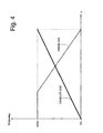
- the actuating device 34 imparts to the butterfly valves 28 and 29 a law of motion in which the main butterfly valve 28 is completely closed when the secondary butterfly valve 29 is completely open and vice versa; furthermore, the actuating device 34 keeps the secondary butterfly valve 29 all open until the main butterfly valve 28 does not reach a predetermined partial opening position.
- FIG 4 the pattern of the position (i.e. of the opening/closing degree) of the secondary butterfly valve 29 is shown by a dashed line and the pattern of the position (i.e. of the opening/closing degree) of the main butterfly valve 28 is shown with a solid line according to the position ⁇ of the shaft of the electrical motor 35 (shown in abscissa).
- the relationship between the position of the main butterfly valve 28 and the position of the secondary butterfly valve 29 can be easily modified by varying the conformation (shape and/or size) of the arm 41 of the connecting element 36; thus the relationship between the position of the main butterfly valve 28 and the position of the secondary butterfly valve 29 shown in figure 4 is only an example of the many relationships which can be obtained by means of the actuating device 34.
- the relationship between the position of the main butterfly valve 28 and the position of the secondary butterfly valve 29 may be easily modified, simply by varying the angle between the two segments of the arm 41 and/or by varying the length of the two segments of the arm 41. In this manner, with a simple modification of the arm 41 of the connecting element 36, it is possible to even substantially modify the mixing features of the exhaust gas present in the inlet conduit 25 with the fresh air in the inlet conduit 26.
- the actuating device 34 also comprises a return spring which tends to push the butterfly valves 28 and 29 towards a neutral position in which the secondary butterfly valve 29 is all open and the main butterfly valve 28 is all closed and thus in complete absence of exhaust gas recirculating in the intake conduit 6.
- the return spring guarantees that the butterfly valves 28 and 29 are moved and kept in neutral position free from recirculated exhaust gases in the intake conduit 6.
- the shaft 31 of the main butterfly valve 28 has an external portion 47, which protrudes from the inlet conduit 25 (through a through hole provided with a seal) to be coupled to the actuating device 34; similarly, the shaft 33 of the secondary butterfly valve 29 also has an external portion 48, which protrudes from the inlet conduit 26 (through a through hole provided with a seal) to couple to the actuating device 34.
- the actuating device 34 comprises a box 49, inside which the external portion 47 of the shaft 31 of the main butterfly valve 28 and the external portion 48 of the shaft 33 of the secondary butterfly valve 29 penetrate.
- the electrical motor 35 and the gear transmission 37 are further accommodated in the box 49.
- the box 49 is provided with a removable cover 50, which is provided with an annular seat for ensuring an adequate tightness. Furthermore, the box 49 has a cylindrical housing 51, which extends perpendicularly to a bottom wall 52 of the box 49 and accommodates the electric motor 35 therein. The bottom wall 52 of the box 49 has two through holes (not shown) for allowing the passage of the shafts 31 and 23 of the butterfly valves 28 and 29.
- the box 49 is only supported by the inlet conduit 26 (i.e. does not touch the inlet conduit 25 in any manner and is instead arranged at a given distance from the inlet conduit 25 itself). Furthermore, the box 49 is independent and separable from the inlet conduit 26 and is fixed to the inlet conduit 26 by means of screws.
- the heat of the inlet conduit 25 may be transmitted to the box 49 only by radiation or convection and not by conduction; the overheating of the box 49 can be limited in this manner.
- at least one part of the external portion 47 of the shaft 31 of the main butterfly valve 28 is made of a heat-insulating material; in particular, the external portion 47 of the shaft 31 of the main butterfly valve 28 comprises an insert 53 made of heat-insulating material, and in particular of refractory material (typically ceramic). It is worth noting that the insert 53 has the function of both heat insulation (i.e. of obstructing the transmission of heat by conduction along the shaft 31 and towards the box 49 and the gear transmission 37) and motion transmission (i.e. of transmitting rotation motion along the shaft 31 between butterfly cap 30 and gear transmission 37).
- the insert 53 made of heat-insulating material constitutes part of the external portion 47 of the shaft 31 of the main butterfly valve 28 and is arranged between two sections of the external portion 47 so as to thermally separate the two sections of the external portion 47 (i.e. preventing a heat transmission by conduction) maintaining a mechanical continuity of the shaft 31 to transmit the rotation movement along the shaft 31 between the butterfly cap 30 and the gear transmission 37.
- each fixed joint between the insert 53 and the section of the external portion 47 comprises a cross-shaped protuberance 54, which axially rises from the insert 53 and is inserted in a seat 55, which is obtained in the section of the external portion 47 which negatively reproduces the shape of the protuberance 54.
- the cylindrical housing 51 is provided with a plurality of cooling fins 56, which thermally connect a wall of the cylindrical housing 51 to a wall of the inlet conduit 26.
- each cooling fin 54 is radially arranged with respect to the cylindrical housing 51 and fully envelops the cylinder housing 51 itself.
- the inlet conduit 25 is provided with a plurality of cooling fins 57 preferably arranged axially (i.e. parallel to the central axis of the inlet conduit 25).
- the above-described mixing device 23 has many advantages.
- the above-described mixing device 23 is simple and cost-effective to make, because a single electrical motor 35 allows to suitably control both the main butterfly valve 28 and the secondary butterfly valve 29.
- modifying the mixing features of the exhaust gases in the EGR conduit 22 with the fresh air present in the intake conduit 6 is simple by modifying the relationship between the portion of the main butterfly valve 28 and the position of the secondary butterfly valve 29 by means of a simple replacement of the arm 41 of the connecting element 36 (arm 41 which has a very low replacement cost).
- the above-described mixing device 23 is very reliable over time, because the electrical motor 35 is adequately protected from excessive overheating essentially caused by the heat transmitted by the inlet conduit 25, which is heated by the exhaust gases which indicatively have a temperature of 350-400 °C.
- the thermal protection of the electrical motor 35 is obtained by creating a separation between the box 49 and the inlet conduit 25, by inserting the insert 53 made of heat-insulating material in the external portion 47 of the shaft 31 of the main butterfly valve 28, thus making the cooling fins 56 between the housing 51 and the inlet conduit 26 and making the cooling fins 57 of the inlet conduit 25.
- the mixing device 23 has a modular structure, because the actuating device 34 is completely contained in the box 49 which can be separated from the inlet conduits 25 and 26 and from the outlet conduit 27; in this manner, the box 49 itself (i.e. the actuating device 34 itself) may be fitted on conduits 25, 26 and 27 of variable size so as to make a wide range of mixing devices 23 which differ from one another by the active flow rate.
Landscapes
- Engineering & Computer Science (AREA)
- Chemical & Material Sciences (AREA)
- Combustion & Propulsion (AREA)
- Mechanical Engineering (AREA)
- General Engineering & Computer Science (AREA)
- Health & Medical Sciences (AREA)
- Toxicology (AREA)
- Exhaust-Gas Circulating Devices (AREA)
Claims (15)
- Mischvorrichtung (23) für ein Niederdruck-AGR-System (21) einer Brennkraftmaschine; die Mischvorrichtung (23) weist auf:eine erste Eintrittsleitung (25), die an eine AGR-Leitung (22) angeschlossen werden kann;eine zweite Eintrittsleitung (26), die an einen Einlass für Frischluft von außen angeschlossen werden kann;eine Austrittsleitung (27), die an eine Einlassleitung (6) angeschlossen werden kann;eine Hauptdrossel (28), die innerhalb der ersten Eintrittsleitung (25) angeordnet ist, um den Querschnitt der ersten Eintrittsleitung (25) zu verändern;eine Nebendrossel (29), die innerhalb der zweiten Eintrittsleitung (26) angeordnet ist, um den Querschnitt der zweiten Eintrittsleitung (26) zu verändern; undeine Betätigungsvorrichtung (34), welche die Hauptdrossel (28) und die Nebendrossel (29) steuert und mit einem Verbindungselement (36), das eine mechanische Verbindung zwischen der Hauptdrossel (28) und der Nebendrossel (29) herstellt, versehen ist, sodass die Stellungen der zwei Drosseln (28, 29) mechanisch miteinander verknüpft sind;wobei die Hauptdrossel (28) eine erste Drosselplatte (30) und eine erste Welle (31), welche die erste Drosselplatte (30) hält, aufweist und einen ersten äußeren Teil (47) besitzt, der aus der ersten Eintrittsleitung (25) ragt, um mit der Betätigungsvorrichtung (34) zusammengesteckt zu werden;wobei die Nebendrossel (29) eine zweite Drosselplatte (32) und eine die zweite Drosselplatte (32) haltende, zweite Welle (33) aufweist und einen zweiten äußeren Teil (48) besitzt, der aus der zweiten Eintrittsleitung (26) ragt, um mit der Betätigungsvorrichtung (34) zusammengesteckt zu werden; undwobei die Betätigungsvorrichtung (34) eine Dose (49), in die der erste äußere Teil (47) der ersten Welle (31) der Hauptdrossel (28) und der zweite äußere Teil (48) der zweiten Welle (33) der Nebendrossel (29) eindringen, und einen Elektromotor (35), der in ein zylindrisches Gehäuse (51) der Dose (49) eingesetzt ist, aufweist;die Mischvorrichtung (23) ist dadurch gekennzeichnet, dass:die Betätigungsvorrichtung (34) einen einzelnen gemeinsamen Elektromotor (35) aufweist, der in ein zylindrisches Gehäuse (51) der Dose (49) eingesetzt ist; unddas zylindrische Gehäuse (51) mit einer Vielzahl erster Kühlrippen (56) versehen ist, die eine Wand des zylindrischen Gehäuses (51) thermisch mit einer Wand der zweiten Eintrittsleitung (26) verbinden.
- Mischvorrichtung (23) nach Anspruch 1, wobei das Verbindungselement (36) einen starren Arm (41) mit einem ersten Ende (43), das mit einer zweiten Welle (33) der Nebendrossel (29) exzentrisch verbunden ist, und einem zweiten Ende (42), das sich gegenüber dem ersten Ende (43) befindet und mit einer ersten Welle (31) der Hauptdrossel (28) exzentrisch verbunden ist, aufweist.
- Mischvorrichtung (23) nach Anspruch 2, wobei:das erste Ende (43) des Arms (41) einen verlängerten Sitz (44) besitzt, der von einem mit der zweiten Welle (31) der Hauptdrossel (28) einteiligen, exzentrischen Stift (45) drehbar und gleitend ergriffen wird; unddas erste Ende (42) des Arms (41) mit der ersten Welle (31) der Hauptdrossel (28) exzentrisch angelenkt verbunden ist.
- Mischvorrichtung (23) nach Anspruch 3, wobei der starre Arm (41) ein erstes Segment, welches das erste Ende (43) und den verlängerten Sitz (44) aufweist, und ein zweites Segment, welches das zweite Ende (42) aufweist, besitzt; das zweite Segment ist länger als das erste Segment und bildet mit dem ersten Segment einen stumpfen Winkel.
- Mischvorrichtung (23) nach Anspruch 2, 3 oder 4, wobei es durch Ändern der Gestaltung des Arms (41) des Verbindungselements (36) möglich ist, die Beziehung zwischen der Stellung der Hauptdrossel (28) und der Stellung der Nebendrossel (29) zu ändern, um die Mischungseigenschaften der Abgase in der ersten Eintrittsleitung (25) mit Frischluft in der zweiten Eintrittsleitung (26) zu ändern.
- Mischvorrichtung (23) nach einem der Ansprüche 1 bis 5, wobei infolge der Wirkung der Betätigungsvorrichtung (34) die Nebendrossel (29) vollständig geöffnet ist, wenn die Hauptdrossel (28) vollständig geschlossen ist und umgekehrt.
- Mischvorrichtung (23) nach Anspruch 6, wobei die Betätigungsvorrichtung (34) die Nebendrossel (29) vollständig geöffnet hält, bis die Hauptdrossel (28) eine vorgegebene, teilweise geöffnete Stellung erreicht.
- Mischvorrichtung (23) nach einem der Ansprüche 1 bis 7, wobei die Hauptdrossel (28) eine erste Drosselplatte (30) und eine die erste Drosselplatte (30) haltende, erste Welle (31) aufweist und einen ersten äußeren Teil (47) besitzt, der aus der ersten Eintrittsleitung (25) ragt, um mit der Betätigungsvorrichtung (34) zusammengesteckt zu werden; mindestens ein Teil des ersten äußeren Teils (47) der ersten Welle (31) der Hauptdrossel (28) ist aus thermisch isolierendem Material hergestellt.
- Mischvorrichtung (23) nach Anspruch 8, wobei der erste äußere Teil (47) der ersten Welle (31) der Hauptdrossel (28) einen aus wärmeisolierendem Material und insbesondere feuerfestem Material hergestellten Einsatz (53) aufweist.
- Mischvorrichtung (23) nach Anspruch 9, wobei der aus wärmeisolierendem Material hergestellte Einsatz (53) Teil des ersten äußeren Teils (47) der ersten Welle (31) der Hauptdrossel (28) ist und zwischen zwei Abschnitte des ersten äußeren Teils (47) eingefügt ist, um die zwei Abschnitte des ersten äußeren Teils (47) unter Beibehaltung der mechanischen Kontinuität auf der ersten Welle (33) thermisch zu trennen.
- Mischvorrichtung (23) nach Anspruch 10, wobei der aus wärmeisolierendem Material hergestellte Einsatz (53) auf beiden Seiten mechanisch in die entsprechenden Abschnitte des ersten äußeren Teils (47) mittels fester Verbindungen passt, die auch einen winkelförmige Verband besitzen, um die relative Drehung zwischen dem Einsatz (53) und den zwei Abschnitten des ersten äußeren Teils (47) zu verhindern, damit die Drehbewegung entlang der ersten Welle (31) übertragen wird.
- Mischvorrichtung (23) nach einem der Ansprüche 1 bis 11, wobei die Dose (49) nur von der zweiten Eintrittsleitung (26) gehalten wird.
- Mischvorrichtung (23) nach Anspruch 12, wobei die Dose (49) unabhängig und von der zweiten Eintrittleitung (26) trennbar ist und mittels Schrauben an der zweiten Eintrittsleitung (26) befestigt ist.
- Mischvorrichtung (23) nach einem der Ansprüche 1 bis 13, wobei jede erste Kühlrippe (56) radial in Bezug auf das zylindrische Gehäuse (51) angeordnet ist und das zylindrische Gehäuse (51) ganz umschließt.
- Mischvorrichtung (23) nach einem der Ansprüche 1 bis 14, wobei die erste Eintrittsleitung (25) mit einer Vielzahl zweiter Kühlrippen (57) vorzugsweise in axialer Anordnung versehen ist.
Applications Claiming Priority (1)
| Application Number | Priority Date | Filing Date | Title |
|---|---|---|---|
| IT000702A ITBO20090702A1 (it) | 2009-10-28 | 2009-10-28 | Dispositivo miscelatore per un sistema egr di bassa pressione di un motore a combustione interna |
Publications (2)
| Publication Number | Publication Date |
|---|---|
| EP2317111A1 EP2317111A1 (de) | 2011-05-04 |
| EP2317111B1 true EP2317111B1 (de) | 2012-03-21 |
Family
ID=42077045
Family Applications (1)
| Application Number | Title | Priority Date | Filing Date |
|---|---|---|---|
| EP10189227A Not-in-force EP2317111B1 (de) | 2009-10-28 | 2010-10-28 | Mischvorrichtung für ein Niederdruck-AGR-System einer Brennkraftmaschine |
Country Status (3)
| Country | Link |
|---|---|
| EP (1) | EP2317111B1 (de) |
| AT (1) | ATE550541T1 (de) |
| IT (1) | ITBO20090702A1 (de) |
Cited By (1)
| Publication number | Priority date | Publication date | Assignee | Title |
|---|---|---|---|---|
| EP3140529B1 (de) | 2014-05-09 | 2018-05-09 | Pierburg GmbH | Abgasturbolader mit einem waste-gate-ventil |
Families Citing this family (25)
| Publication number | Priority date | Publication date | Assignee | Title |
|---|---|---|---|---|
| EP2497921A1 (de) * | 2011-03-08 | 2012-09-12 | Delphi Automotive Systems Luxembourg SA | Drosselventilanordnung |
| DE102012203156B4 (de) * | 2012-02-29 | 2014-01-09 | Continental Automotive Gmbh | Mischventil einer Brennkraftmaschine |
| DE102012101767B4 (de) * | 2012-03-02 | 2015-01-08 | Pierburg Gmbh | Verbrennungskraftmaschine |
| EP2662556B1 (de) * | 2012-05-09 | 2015-02-18 | Continental Automotive GmbH | Mischventil einer Brennkraftmaschine |
| FR2990726B1 (fr) * | 2012-05-15 | 2015-08-21 | Valeo Sys Controle Moteur Sas | Doseur deux voies et applications dudit doseur |
| DE102012224232A1 (de) | 2012-12-21 | 2014-06-26 | Continental Automotive Gmbh | Ventil |
| US10018157B2 (en) | 2013-03-14 | 2018-07-10 | Ford Global Technologies, Llc | Methods and systems for boost control |
| FR3007071B1 (fr) * | 2013-06-17 | 2017-02-10 | Peugeot Citroen Automobiles Sa | Moteur thermique a actionneur commun pour vanne egr et vanne d'air |
| US9261051B2 (en) | 2013-08-13 | 2016-02-16 | Ford Global Technologies, Llc | Methods and systems for boost control |
| US9080506B2 (en) | 2013-08-13 | 2015-07-14 | Ford Global Technologies, Llc | Methods and systems for boost control |
| US9174637B2 (en) | 2013-08-13 | 2015-11-03 | Ford Global Technologies, Llc | Methods and systems for torque control |
| US9151219B2 (en) | 2013-08-13 | 2015-10-06 | Ford Global Technologies, Llc | Methods and systems for surge control |
| US9309837B2 (en) | 2013-08-13 | 2016-04-12 | Ford Global Technologies, Llc | Methods and systems for EGR control |
| US9091202B2 (en) | 2013-08-13 | 2015-07-28 | Ford Global Technologies, Llc | Methods and systems for boost control |
| US9303557B2 (en) | 2013-08-13 | 2016-04-05 | Ford Global Technologies, Llc | Methods and systems for EGR control |
| US9309836B2 (en) | 2013-08-13 | 2016-04-12 | Ford Global Technologies, Llc | Methods and systems for boost control |
| US9109505B2 (en) | 2013-08-13 | 2015-08-18 | Ford Global Technologies, Llc | Methods and systems for condensation control |
| US9279374B2 (en) | 2013-08-13 | 2016-03-08 | Ford Global Technologies, Llc | Methods and systems for surge control |
| US9682685B2 (en) | 2013-08-13 | 2017-06-20 | Ford Global Technologies, Llc | Methods and systems for condensation control |
| US9759135B2 (en) * | 2014-04-04 | 2017-09-12 | Ford Global Technologies, Llc | Method and system for engine control |
| DE102014214709A1 (de) * | 2014-07-25 | 2016-01-28 | Continental Automotive Gmbh | Ventilvorrichtung für ein Kraftfahrzeug |
| CA2997893C (en) * | 2015-09-07 | 2022-08-30 | Nissan Motor Co., Ltd. | Exhaust gas recirculation control method and exhaust gas recirculation control device |
| DE102016215872B4 (de) * | 2016-08-24 | 2024-11-07 | Ford Global Technologies, Llc | Aufgeladene Brennkraftmaschine mit Verdichter, Abgasrückführung und Ventileinheit |
| CN110168209B (zh) * | 2017-01-16 | 2022-03-04 | 日产自动车株式会社 | 内燃机的控制方法以及内燃机的控制装置 |
| FR3067062B1 (fr) * | 2017-06-01 | 2019-06-21 | Peugeot Citroen Automobiles Sa | Procede de commande de debit de moyens de dosage d’air et de moyens de gaz brules recircules dans un groupe motopropulseur |
Family Cites Families (10)
| Publication number | Priority date | Publication date | Assignee | Title |
|---|---|---|---|---|
| US2722927A (en) * | 1952-10-29 | 1955-11-08 | George W Cornelius | Apparatus for controlling internal combustion engine fuel mixtures |
| JPS5252028A (en) * | 1975-10-24 | 1977-04-26 | Toyota Motor Corp | Internal engine exhaust recycling device |
| CA2003218A1 (en) * | 1988-11-18 | 1990-05-18 | Minobu Sukimoto | Adapter for intake manifold |
| SE521713C2 (sv) * | 1998-11-09 | 2003-12-02 | Stt Emtec Ab | Förfarande och anordning för ett EGR-system, samt dylik ventil |
| EP1270924A3 (de) * | 2001-06-28 | 2004-01-07 | Delphi Technologies, Inc. | Integriertes Ansaugmodul für eine Brennkraftmaschine |
| SE526824C2 (sv) * | 2004-03-26 | 2005-11-08 | Stt Emtec Ab | Ventil |
| JP2006214405A (ja) * | 2005-02-07 | 2006-08-17 | Hitachi Ltd | 内燃機関の排気ガス還流装置および内燃機関のバルブモジュール |
| US7320220B1 (en) * | 2006-12-15 | 2008-01-22 | Caterpillar Inc. | EGR valve having integrated motor, controller, and flow meter |
| FR2926114B1 (fr) * | 2008-01-03 | 2012-12-14 | Valeo Sys Controle Moteur Sas | Boucle egr d'un moteur a combustion interne d'un vehicule automobile |
| EP2085601B1 (de) * | 2008-02-04 | 2011-05-25 | Kamtec Inc. | Abgasrückführungsventil für Fahrzeug |
-
2009
- 2009-10-28 IT IT000702A patent/ITBO20090702A1/it unknown
-
2010
- 2010-10-28 AT AT10189227T patent/ATE550541T1/de active
- 2010-10-28 EP EP10189227A patent/EP2317111B1/de not_active Not-in-force
Cited By (1)
| Publication number | Priority date | Publication date | Assignee | Title |
|---|---|---|---|---|
| EP3140529B1 (de) | 2014-05-09 | 2018-05-09 | Pierburg GmbH | Abgasturbolader mit einem waste-gate-ventil |
Also Published As
| Publication number | Publication date |
|---|---|
| ITBO20090702A1 (it) | 2011-04-28 |
| ATE550541T1 (de) | 2012-04-15 |
| EP2317111A1 (de) | 2011-05-04 |
Similar Documents
| Publication | Publication Date | Title |
|---|---|---|
| EP2317111A1 (de) | Mischvorrichtung für ein Niederruck-AGR-System einer Brennkraftmaschine | |
| CN109072770B (zh) | 用于废气涡轮增压器的带双通道涡轮机壳体和用于通道连接的阀的涡轮机 | |
| EP2558752B1 (de) | Multifunktionsventil | |
| EP1103715B1 (de) | Abgasrückführungsvorrichtung für eine Brennkraftmaschine | |
| CA2402173A1 (en) | Intelligent electric actuator for control of a turbocharger with an integrated exhaust gas recirculation valve | |
| CN105102801A (zh) | 低压排气再循环模块相关申请的交叉引用 | |
| US20130309106A1 (en) | Turbocharger | |
| EP2148060B1 (de) | Saugrohr mit einem Drallsystems für einen Verbrennungsmotor | |
| CN109154229B (zh) | 用于废气涡轮增压器的涡轮机 | |
| EP1908943B1 (de) | Ansaugkrümmer mit veränderbarer Form für eine Brennkraftmaschine | |
| CN107683364B (zh) | 具有可调整涡轮机几何构型的排气涡轮增压器 | |
| RU146120U1 (ru) | Регулятор давления наддува турбонагнетателя (варианты) | |
| EP1996811B1 (de) | Zweiteiliges agr-modul mit niedrigem druck | |
| US9103235B2 (en) | Valve drive apparatus and supercharger having the same | |
| EP2375046A1 (de) | Mischvorrichtung mit einem einzigen Ventil für ein Niederdruck-AGR-System einer Brennkraftmaschine | |
| KR100546749B1 (ko) | 과급기용모듈식바이패스시스템 | |
| WO2019054393A1 (ja) | 弁装置 | |
| US8316812B2 (en) | Dual output flow control actuator | |
| PT1770263E (pt) | Colector de admissão de um sistema de turbulência para um motor de combustão interna | |
| WO2009115975A3 (en) | Egr valve for exhaust gas recirculation to the intake manifold of internal combustion engines | |
| US12000353B2 (en) | Intake system | |
| EP1136688B1 (de) | Abgasrückführvorrichtung für eine Brennkraftmaschine | |
| EP3144508B1 (de) | Elektromechanischer aktuator zur betätigung einer verwendungsvorrichtung eines verbrennungsmotors | |
| EP1923550A2 (de) | Bypassbaugruppe für einen Systemluftkühler | |
| GB2535995A (en) | A geared valve system |
Legal Events
| Date | Code | Title | Description |
|---|---|---|---|
| PUAI | Public reference made under article 153(3) epc to a published international application that has entered the european phase |
Free format text: ORIGINAL CODE: 0009012 |
|
| AK | Designated contracting states |
Kind code of ref document: A1 Designated state(s): AL AT BE BG CH CY CZ DE DK EE ES FI FR GB GR HR HU IE IS IT LI LT LU LV MC MK MT NL NO PL PT RO RS SE SI SK SM TR |
|
| AX | Request for extension of the european patent |
Extension state: BA ME |
|
| 17P | Request for examination filed |
Effective date: 20110420 |
|
| GRAP | Despatch of communication of intention to grant a patent |
Free format text: ORIGINAL CODE: EPIDOSNIGR1 |
|
| RIC1 | Information provided on ipc code assigned before grant |
Ipc: F02M 25/07 20060101AFI20110906BHEP |
|
| GRAS | Grant fee paid |
Free format text: ORIGINAL CODE: EPIDOSNIGR3 |
|
| GRAA | (expected) grant |
Free format text: ORIGINAL CODE: 0009210 |
|
| AK | Designated contracting states |
Kind code of ref document: B1 Designated state(s): AL AT BE BG CH CY CZ DE DK EE ES FI FR GB GR HR HU IE IS IT LI LT LU LV MC MK MT NL NO PL PT RO RS SE SI SK SM TR |
|
| REG | Reference to a national code |
Ref country code: GB Ref legal event code: FG4D |
|
| REG | Reference to a national code |
Ref country code: CH Ref legal event code: EP |
|
| REG | Reference to a national code |
Ref country code: IE Ref legal event code: FG4D |
|
| REG | Reference to a national code |
Ref country code: AT Ref legal event code: REF Ref document number: 550541 Country of ref document: AT Kind code of ref document: T Effective date: 20120415 |
|
| REG | Reference to a national code |
Ref country code: DE Ref legal event code: R096 Ref document number: 602010001110 Country of ref document: DE Effective date: 20120524 |
|
| REG | Reference to a national code |
Ref country code: NL Ref legal event code: VDEP Effective date: 20120321 |
|
| PG25 | Lapsed in a contracting state [announced via postgrant information from national office to epo] |
Ref country code: HR Free format text: LAPSE BECAUSE OF FAILURE TO SUBMIT A TRANSLATION OF THE DESCRIPTION OR TO PAY THE FEE WITHIN THE PRESCRIBED TIME-LIMIT Effective date: 20120321 Ref country code: LT Free format text: LAPSE BECAUSE OF FAILURE TO SUBMIT A TRANSLATION OF THE DESCRIPTION OR TO PAY THE FEE WITHIN THE PRESCRIBED TIME-LIMIT Effective date: 20120321 Ref country code: NO Free format text: LAPSE BECAUSE OF FAILURE TO SUBMIT A TRANSLATION OF THE DESCRIPTION OR TO PAY THE FEE WITHIN THE PRESCRIBED TIME-LIMIT Effective date: 20120621 |
|
| LTIE | Lt: invalidation of european patent or patent extension |
Effective date: 20120321 |
|
| PG25 | Lapsed in a contracting state [announced via postgrant information from national office to epo] |
Ref country code: FI Free format text: LAPSE BECAUSE OF FAILURE TO SUBMIT A TRANSLATION OF THE DESCRIPTION OR TO PAY THE FEE WITHIN THE PRESCRIBED TIME-LIMIT Effective date: 20120321 Ref country code: GR Free format text: LAPSE BECAUSE OF FAILURE TO SUBMIT A TRANSLATION OF THE DESCRIPTION OR TO PAY THE FEE WITHIN THE PRESCRIBED TIME-LIMIT Effective date: 20120622 Ref country code: RS Free format text: LAPSE BECAUSE OF FAILURE TO SUBMIT A TRANSLATION OF THE DESCRIPTION OR TO PAY THE FEE WITHIN THE PRESCRIBED TIME-LIMIT Effective date: 20120321 Ref country code: LV Free format text: LAPSE BECAUSE OF FAILURE TO SUBMIT A TRANSLATION OF THE DESCRIPTION OR TO PAY THE FEE WITHIN THE PRESCRIBED TIME-LIMIT Effective date: 20120321 |
|
| REG | Reference to a national code |
Ref country code: AT Ref legal event code: MK05 Ref document number: 550541 Country of ref document: AT Kind code of ref document: T Effective date: 20120321 |
|
| PG25 | Lapsed in a contracting state [announced via postgrant information from national office to epo] |
Ref country code: CY Free format text: LAPSE BECAUSE OF FAILURE TO SUBMIT A TRANSLATION OF THE DESCRIPTION OR TO PAY THE FEE WITHIN THE PRESCRIBED TIME-LIMIT Effective date: 20120321 |
|
| PG25 | Lapsed in a contracting state [announced via postgrant information from national office to epo] |
Ref country code: CZ Free format text: LAPSE BECAUSE OF FAILURE TO SUBMIT A TRANSLATION OF THE DESCRIPTION OR TO PAY THE FEE WITHIN THE PRESCRIBED TIME-LIMIT Effective date: 20120321 Ref country code: SE Free format text: LAPSE BECAUSE OF FAILURE TO SUBMIT A TRANSLATION OF THE DESCRIPTION OR TO PAY THE FEE WITHIN THE PRESCRIBED TIME-LIMIT Effective date: 20120321 Ref country code: EE Free format text: LAPSE BECAUSE OF FAILURE TO SUBMIT A TRANSLATION OF THE DESCRIPTION OR TO PAY THE FEE WITHIN THE PRESCRIBED TIME-LIMIT Effective date: 20120321 Ref country code: IS Free format text: LAPSE BECAUSE OF FAILURE TO SUBMIT A TRANSLATION OF THE DESCRIPTION OR TO PAY THE FEE WITHIN THE PRESCRIBED TIME-LIMIT Effective date: 20120721 Ref country code: BE Free format text: LAPSE BECAUSE OF FAILURE TO SUBMIT A TRANSLATION OF THE DESCRIPTION OR TO PAY THE FEE WITHIN THE PRESCRIBED TIME-LIMIT Effective date: 20120321 Ref country code: SI Free format text: LAPSE BECAUSE OF FAILURE TO SUBMIT A TRANSLATION OF THE DESCRIPTION OR TO PAY THE FEE WITHIN THE PRESCRIBED TIME-LIMIT Effective date: 20120321 Ref country code: RO Free format text: LAPSE BECAUSE OF FAILURE TO SUBMIT A TRANSLATION OF THE DESCRIPTION OR TO PAY THE FEE WITHIN THE PRESCRIBED TIME-LIMIT Effective date: 20120321 Ref country code: PL Free format text: LAPSE BECAUSE OF FAILURE TO SUBMIT A TRANSLATION OF THE DESCRIPTION OR TO PAY THE FEE WITHIN THE PRESCRIBED TIME-LIMIT Effective date: 20120321 |
|
| PG25 | Lapsed in a contracting state [announced via postgrant information from national office to epo] |
Ref country code: PT Free format text: LAPSE BECAUSE OF FAILURE TO SUBMIT A TRANSLATION OF THE DESCRIPTION OR TO PAY THE FEE WITHIN THE PRESCRIBED TIME-LIMIT Effective date: 20120723 Ref country code: SK Free format text: LAPSE BECAUSE OF FAILURE TO SUBMIT A TRANSLATION OF THE DESCRIPTION OR TO PAY THE FEE WITHIN THE PRESCRIBED TIME-LIMIT Effective date: 20120321 |
|
| PLBE | No opposition filed within time limit |
Free format text: ORIGINAL CODE: 0009261 |
|
| STAA | Information on the status of an ep patent application or granted ep patent |
Free format text: STATUS: NO OPPOSITION FILED WITHIN TIME LIMIT |
|
| PG25 | Lapsed in a contracting state [announced via postgrant information from national office to epo] |
Ref country code: NL Free format text: LAPSE BECAUSE OF FAILURE TO SUBMIT A TRANSLATION OF THE DESCRIPTION OR TO PAY THE FEE WITHIN THE PRESCRIBED TIME-LIMIT Effective date: 20120321 Ref country code: DK Free format text: LAPSE BECAUSE OF FAILURE TO SUBMIT A TRANSLATION OF THE DESCRIPTION OR TO PAY THE FEE WITHIN THE PRESCRIBED TIME-LIMIT Effective date: 20120321 Ref country code: AT Free format text: LAPSE BECAUSE OF FAILURE TO SUBMIT A TRANSLATION OF THE DESCRIPTION OR TO PAY THE FEE WITHIN THE PRESCRIBED TIME-LIMIT Effective date: 20120321 |
|
| 26N | No opposition filed |
Effective date: 20130102 |
|
| REG | Reference to a national code |
Ref country code: DE Ref legal event code: R097 Ref document number: 602010001110 Country of ref document: DE Effective date: 20130102 |
|
| PG25 | Lapsed in a contracting state [announced via postgrant information from national office to epo] |
Ref country code: ES Free format text: LAPSE BECAUSE OF FAILURE TO SUBMIT A TRANSLATION OF THE DESCRIPTION OR TO PAY THE FEE WITHIN THE PRESCRIBED TIME-LIMIT Effective date: 20120702 |
|
| PG25 | Lapsed in a contracting state [announced via postgrant information from national office to epo] |
Ref country code: MC Free format text: LAPSE BECAUSE OF NON-PAYMENT OF DUE FEES Effective date: 20121031 |
|
| PG25 | Lapsed in a contracting state [announced via postgrant information from national office to epo] |
Ref country code: BG Free format text: LAPSE BECAUSE OF FAILURE TO SUBMIT A TRANSLATION OF THE DESCRIPTION OR TO PAY THE FEE WITHIN THE PRESCRIBED TIME-LIMIT Effective date: 20120621 |
|
| REG | Reference to a national code |
Ref country code: IE Ref legal event code: MM4A |
|
| PG25 | Lapsed in a contracting state [announced via postgrant information from national office to epo] |
Ref country code: IE Free format text: LAPSE BECAUSE OF NON-PAYMENT OF DUE FEES Effective date: 20121028 |
|
| PG25 | Lapsed in a contracting state [announced via postgrant information from national office to epo] |
Ref country code: MT Free format text: LAPSE BECAUSE OF FAILURE TO SUBMIT A TRANSLATION OF THE DESCRIPTION OR TO PAY THE FEE WITHIN THE PRESCRIBED TIME-LIMIT Effective date: 20120321 Ref country code: AL Free format text: LAPSE BECAUSE OF FAILURE TO SUBMIT A TRANSLATION OF THE DESCRIPTION OR TO PAY THE FEE WITHIN THE PRESCRIBED TIME-LIMIT Effective date: 20120321 |
|
| PG25 | Lapsed in a contracting state [announced via postgrant information from national office to epo] |
Ref country code: SM Free format text: LAPSE BECAUSE OF FAILURE TO SUBMIT A TRANSLATION OF THE DESCRIPTION OR TO PAY THE FEE WITHIN THE PRESCRIBED TIME-LIMIT Effective date: 20120321 Ref country code: LU Free format text: LAPSE BECAUSE OF NON-PAYMENT OF DUE FEES Effective date: 20121028 |
|
| PG25 | Lapsed in a contracting state [announced via postgrant information from national office to epo] |
Ref country code: HU Free format text: LAPSE BECAUSE OF FAILURE TO SUBMIT A TRANSLATION OF THE DESCRIPTION OR TO PAY THE FEE WITHIN THE PRESCRIBED TIME-LIMIT Effective date: 20101028 |
|
| REG | Reference to a national code |
Ref country code: CH Ref legal event code: PL |
|
| GBPC | Gb: european patent ceased through non-payment of renewal fee |
Effective date: 20141028 |
|
| PG25 | Lapsed in a contracting state [announced via postgrant information from national office to epo] |
Ref country code: CH Free format text: LAPSE BECAUSE OF NON-PAYMENT OF DUE FEES Effective date: 20141031 Ref country code: MK Free format text: LAPSE BECAUSE OF FAILURE TO SUBMIT A TRANSLATION OF THE DESCRIPTION OR TO PAY THE FEE WITHIN THE PRESCRIBED TIME-LIMIT Effective date: 20120321 Ref country code: GB Free format text: LAPSE BECAUSE OF NON-PAYMENT OF DUE FEES Effective date: 20141028 Ref country code: LI Free format text: LAPSE BECAUSE OF NON-PAYMENT OF DUE FEES Effective date: 20141031 |
|
| REG | Reference to a national code |
Ref country code: FR Ref legal event code: PLFP Year of fee payment: 7 |
|
| REG | Reference to a national code |
Ref country code: FR Ref legal event code: PLFP Year of fee payment: 8 |
|
| REG | Reference to a national code |
Ref country code: FR Ref legal event code: PLFP Year of fee payment: 9 |
|
| PGFP | Annual fee paid to national office [announced via postgrant information from national office to epo] |
Ref country code: IT Payment date: 20180919 Year of fee payment: 9 Ref country code: FR Payment date: 20180920 Year of fee payment: 9 |
|
| PGFP | Annual fee paid to national office [announced via postgrant information from national office to epo] |
Ref country code: DE Payment date: 20180819 Year of fee payment: 9 |
|
| PGFP | Annual fee paid to national office [announced via postgrant information from national office to epo] |
Ref country code: TR Payment date: 20181003 Year of fee payment: 9 |
|
| REG | Reference to a national code |
Ref country code: DE Ref legal event code: R119 Ref document number: 602010001110 Country of ref document: DE |
|
| PG25 | Lapsed in a contracting state [announced via postgrant information from national office to epo] |
Ref country code: DE Free format text: LAPSE BECAUSE OF NON-PAYMENT OF DUE FEES Effective date: 20200501 |
|
| PG25 | Lapsed in a contracting state [announced via postgrant information from national office to epo] |
Ref country code: IT Free format text: LAPSE BECAUSE OF NON-PAYMENT OF DUE FEES Effective date: 20191028 Ref country code: FR Free format text: LAPSE BECAUSE OF NON-PAYMENT OF DUE FEES Effective date: 20191031 |
|
| PG25 | Lapsed in a contracting state [announced via postgrant information from national office to epo] |
Ref country code: TR Free format text: LAPSE BECAUSE OF NON-PAYMENT OF DUE FEES Effective date: 20191028 |