EP2317143B1 - Pompe à vis excentrique - Google Patents
Pompe à vis excentrique Download PDFInfo
- Publication number
- EP2317143B1 EP2317143B1 EP10014006.0A EP10014006A EP2317143B1 EP 2317143 B1 EP2317143 B1 EP 2317143B1 EP 10014006 A EP10014006 A EP 10014006A EP 2317143 B1 EP2317143 B1 EP 2317143B1
- Authority
- EP
- European Patent Office
- Prior art keywords
- drive unit
- rotor
- conveyed
- stator
- area
- Prior art date
- Legal status (The legal status is an assumption and is not a legal conclusion. Google has not performed a legal analysis and makes no representation as to the accuracy of the status listed.)
- Not-in-force
Links
Images




Classifications
-
- F—MECHANICAL ENGINEERING; LIGHTING; HEATING; WEAPONS; BLASTING
- F04—POSITIVE - DISPLACEMENT MACHINES FOR LIQUIDS; PUMPS FOR LIQUIDS OR ELASTIC FLUIDS
- F04C—ROTARY-PISTON, OR OSCILLATING-PISTON, POSITIVE-DISPLACEMENT MACHINES FOR LIQUIDS; ROTARY-PISTON, OR OSCILLATING-PISTON, POSITIVE-DISPLACEMENT PUMPS
- F04C2/00—Rotary-piston machines or pumps
- F04C2/08—Rotary-piston machines or pumps of intermeshing-engagement type, i.e. with engagement of co-operating members similar to that of toothed gearing
- F04C2/10—Rotary-piston machines or pumps of intermeshing-engagement type, i.e. with engagement of co-operating members similar to that of toothed gearing of internal-axis type with the outer member having more teeth or tooth-equivalents, e.g. rollers, than the inner member
- F04C2/107—Rotary-piston machines or pumps of intermeshing-engagement type, i.e. with engagement of co-operating members similar to that of toothed gearing of internal-axis type with the outer member having more teeth or tooth-equivalents, e.g. rollers, than the inner member with helical teeth
- F04C2/1071—Rotary-piston machines or pumps of intermeshing-engagement type, i.e. with engagement of co-operating members similar to that of toothed gearing of internal-axis type with the outer member having more teeth or tooth-equivalents, e.g. rollers, than the inner member with helical teeth the inner and outer member having a different number of threads and one of the two being made of elastic materials, e.g. Moineau type
-
- B—PERFORMING OPERATIONS; TRANSPORTING
- B60—VEHICLES IN GENERAL
- B60S—SERVICING, CLEANING, REPAIRING, SUPPORTING, LIFTING, OR MANOEUVRING OF VEHICLES, NOT OTHERWISE PROVIDED FOR
- B60S9/00—Ground-engaging vehicle fittings for supporting, lifting, or manoeuvring the vehicle, wholly or in part, e.g. built-in jacks
- B60S9/02—Ground-engaging vehicle fittings for supporting, lifting, or manoeuvring the vehicle, wholly or in part, e.g. built-in jacks for only lifting or supporting
- B60S9/04—Ground-engaging vehicle fittings for supporting, lifting, or manoeuvring the vehicle, wholly or in part, e.g. built-in jacks for only lifting or supporting mechanically
-
- B—PERFORMING OPERATIONS; TRANSPORTING
- B60—VEHICLES IN GENERAL
- B60S—SERVICING, CLEANING, REPAIRING, SUPPORTING, LIFTING, OR MANOEUVRING OF VEHICLES, NOT OTHERWISE PROVIDED FOR
- B60S9/00—Ground-engaging vehicle fittings for supporting, lifting, or manoeuvring the vehicle, wholly or in part, e.g. built-in jacks
- B60S9/22—Means for attaching lifting, supporting, or manoeuvring devices to vehicles
-
- F—MECHANICAL ENGINEERING; LIGHTING; HEATING; WEAPONS; BLASTING
- F04—POSITIVE - DISPLACEMENT MACHINES FOR LIQUIDS; PUMPS FOR LIQUIDS OR ELASTIC FLUIDS
- F04C—ROTARY-PISTON, OR OSCILLATING-PISTON, POSITIVE-DISPLACEMENT MACHINES FOR LIQUIDS; ROTARY-PISTON, OR OSCILLATING-PISTON, POSITIVE-DISPLACEMENT PUMPS
- F04C13/00—Adaptations of machines or pumps for special use, e.g. for extremely high pressures
- F04C13/001—Pumps for particular liquids
- F04C13/002—Pumps for particular liquids for homogeneous viscous liquids
-
- F—MECHANICAL ENGINEERING; LIGHTING; HEATING; WEAPONS; BLASTING
- F04—POSITIVE - DISPLACEMENT MACHINES FOR LIQUIDS; PUMPS FOR LIQUIDS OR ELASTIC FLUIDS
- F04C—ROTARY-PISTON, OR OSCILLATING-PISTON, POSITIVE-DISPLACEMENT MACHINES FOR LIQUIDS; ROTARY-PISTON, OR OSCILLATING-PISTON, POSITIVE-DISPLACEMENT PUMPS
- F04C2230/00—Manufacture
- F04C2230/70—Disassembly methods
-
- F—MECHANICAL ENGINEERING; LIGHTING; HEATING; WEAPONS; BLASTING
- F04—POSITIVE - DISPLACEMENT MACHINES FOR LIQUIDS; PUMPS FOR LIQUIDS OR ELASTIC FLUIDS
- F04C—ROTARY-PISTON, OR OSCILLATING-PISTON, POSITIVE-DISPLACEMENT MACHINES FOR LIQUIDS; ROTARY-PISTON, OR OSCILLATING-PISTON, POSITIVE-DISPLACEMENT PUMPS
- F04C2240/00—Components
- F04C2240/80—Other components
- F04C2240/805—Fastening means, e.g. bolts
Definitions
- the invention relates to a device for conveying viscous conveyed material according to the preamble of claim 1, mortar pump with eccentric screws are known from the prior art. They are partly designed as submersible pumps, which protrude with a suction end in a storage vessel, promote the conveyed from this suction and a discharge line to the processing site, in particular to a mortar spray apparatus. Also horizontal mortar pumps are known, which remove an eccentric screw mortar from a reservoir via a suction and transport it in a pressure range for processing under pressure. In particular, constructions of eccentric screw pumps, for example, from US 4,140,444 , of the US 3,354,537 or the US 2009/0136371 A1 known.
- a problem with the known devices according to the prior art is the cleaning of the eccentric screw pump.
- the rotor which represents the worm
- the stator in which the worm runs.
- the pumping action results from an elastically sealing deformation of the stator when turning the screw, this provides a considerable resistance during disassembly against a simple withdrawal of the screw.
- From the prior art for example from the DE 103 37 382 A1 Devices are known which overcome this resistance. However, these are expensive and must be arranged separately on the device to be cleaned by additional steps.
- the invention has now taken on the task of disassembly of a corresponding device with To simplify the progressing cavity pump.
- the invention relates to a device for conveying viscous conveyed material, for example mortar by means of a progressing cavity pump.
- the apparatus comprises a frame for receiving and fixing device elements, a pump housing section for receiving a stator and a rotor rotatably mounted in the stator in the form of a screw conveyor, a suction area for introducing the conveyed material, a pressure area for dispensing the conveyed material, an electric drive unit for rotating drive the rotor in the stator in a first direction of rotation for conveying the conveyed material, a controller for controlling the drive unit and one or more releasable holding means for non-rotatable and / or stationary connection of the drive unit and the stator.
- a change in the direction of rotation g of the electric drive unit in a second rotational direction when holding means are released carries out an automatic separation of the pump housing section with the stator by unscrewing the rotor.
- These bolts form the rotationally fixed holding means, wherein they can additionally serve as a receptacle for threaded pins, which fasten in a mounted position as oxtsfix Schlude holding means together with corresponding cap nuts, the bolts and thus the pump housing portion of the drive unit or the housing.
- this is characterized in that the rotor is supported during the separation process of the pump housing on the stator and preferably slightly elastically deformed.
- This process corresponds to the usual deformation when conveying in an eccentric screw pump, wherein during conveying, the support of the counteracting force must be applied by the stationary fixing means.
- this is characterized in that with fixed holding means of the rotor during operation depending on the direction of rotation of the drive unit forms a suction or a pressure operation whereby suction and pressure range can be exchanged.
- this is characterized in that the suction region is arranged at an angle of approximately 90 ° to the rotor axis and comprises a preferably funnel-shaped container for receiving the viscous material to be conveyed to the device for the printing operation.
- this is characterized in that the suction region is arranged in an extension to the rotor axis and is preferably immersed in a container for receiving the viscous material to be conveyed.
- This design allows, inter alia, a removal from a mixing vessel or a mixing trough.
- this is characterized in that the suction area is formed with connection means to a container with stored conveyed, preferably a disposable container.
- Reusable containers with industrially prefabricated conveyed material such as mortar or plaster can be provided in appropriate system programs, and provided with special connection means for system-conforming conveyors. Also disposable containers, for example made of cardboard composites are conceivable.
- this is characterized in that at least two successive shaft seals are provided between the drive unit and the rotor in a filling area or suction area for sealing the filling area with respect to the drive unit.
- the drive unit comprises a brushless DC motor and preferably a transmission.
- the use of the properties of brushless DC motors, such as the high torque at low speeds makes the cost and against interference and contamination insensitive construction possible. Reversing the direction of rotation is easy for us to realize cost-effectively, without accepting reductions in performance.
- FIG. 1 a Tauchmörtelpumpe 10.
- the pump comprises a frame 11 at the upper end of the drive unit 12 is attached.
- the frame has a telescopic arrangement 13, which facilitates the introduction of the pump into a storage container (not shown here).
- connection means 21 for a pressure line or a working device.
- FIG. 2 shows a cross section of the eccentric screw pump in a partially disassembled state.
- the drive shaft 31 of the drive unit 12 extends and is connected via coupling means 32 with the eccentric screw 33.
- the eccentric screw 33 extends within the stator 34 and generates according to the principle an eccentric screw pump suction on the suction extension 18 for conveying the material.
- the eccentric screw 33 has already been unscrewed from the stator by the distance 35, which was achieved by a reverse direction of rotation of the drive unit 12 as in the conveying operation.
- the holding means were solved accordingly.
- FIG. 3 shows a completely separated from the rotor (eccentric screw 33) arrangement of the lower housing portion 17.
- the telescopic assembly 13 is extended in this case.
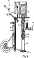
- FIG. 4 shows a more detailed representation of the mortar pump according to the invention in cross section.
- the mortar pump is shown here in a fully assembled state.
- FIG. 5 shows a more detailed representation of the holding means according to the invention.
- the upper housing portion 14 is connected to the lower housing portion 17 via threaded bolts 15 which are pivotally attached thereto.
- the threaded bolts 15 pass through radially, from the lower housing portion 17 outwardly directed bolt 51, which run in a longitudinal slot 52 in the upper housing portion 14.
- the stationary connection of the stationary fixing means of the threaded bolt 15 is produced by cap nuts 16 applied thereto, which fix the bolts 51.
- a loosening the cap nuts 16, which are preferably arranged symmetrically on both opposite sides of the mortar pump, allows the bolt 51 to move along the longitudinal slot 52.
- FIG. 6 shows an upper seal 61 and a lower seal 62, which seal the pressure region 63 in the interior of the pump relative to the drive region and the drive shaft 31 perform.
- a coarser material seal 64 may be provided.
- the pressure range has a control pressure gauge 65, which indicates the reached working pressure.
Landscapes
- Engineering & Computer Science (AREA)
- Mechanical Engineering (AREA)
- General Engineering & Computer Science (AREA)
- Rotary Pumps (AREA)
- Details And Applications Of Rotary Liquid Pumps (AREA)
- Reciprocating Pumps (AREA)
Claims (8)
- Dispositif de refoulement d'un produit visqueux, par exemple du mortier au moyen d'une pompe à vis excentrique, comprenant :- un châssis pour le logement et la fixation d'éléments du dispositif- une portion de carter de pompe pour le logement d'un stator et d'un rotor logé de manière rotative dans le stator sous la forme d'une vis sans fin,- une zone d'aspiration pour l'introduction du produit,- une zone de pression pour la distribution du produit,- une unité d'entraînement électrique pour l'entraînement en rotation du rotor dans le stator dans un premier sens de rotation pour le refoulement du produit,- un dispositif de commande pour la commande de l'unité d'entraînement,- un ou plusieurs moyens de maintien détachables pour la liaison solidaire en rotation et/ou stationnaire de l'unité d'entraînement et du stator, une variation du sens de rotation vers un deuxième sens de rotation de l'unité d'entraînement électrique lorsque les moyens de maintien sont détachés provoquant une séparation automatique de la portion de carter de pompe avec le stator par dévissage du rotor,caractérisé en ce que
sur la portion de carter de pompe, sont disposées deux tiges orientées radialement vers l'extérieur, qui guident linéairement la portion du carter de pompe pendant le processus de séparation dans les moyens de guidage sur le châssis et/ou dans une gaine de carter et/ou une autre portion de carter et/ou un carter de moteur. - Dispositif selon l'une des revendications précédentes, caractérisé en ce que le rotor s'appuie, pendant le processus de séparation du carter de pompe, contre le stator et de préférence déforme celui-ci de manière légèrement élastique.
- Dispositif selon l'une des revendications précédentes, caractérisé en ce que, lorsque les moyens de maintien sont fixés, le rotor constitue, lors du fonctionnement, selon le sens de rotation de l'unité d'entraînement, un fonctionnement d'aspiration ou un fonctionnement de pression, la zone d'aspiration et la zone de pression étant changées.
- Dispositif selon l'une des revendications précédentes, caractérisé en ce que la zone d'aspiration forme un angle d'environ 90° par rapport à l'axe du rotor et comprend un récipient en forme d'entonnoir pour le logement du produit visqueux au niveau du dispositif pour le fonctionnement en pression.
- Dispositif selon l'une des revendications précédentes, caractérisé en ce que la zone d'aspiration est disposée dans un prolongement de l'axe du rotor et peut être immergée dans un récipient pour le logement du produit visqueux.
- Dispositif selon l'une des revendications précédentes, caractérisé en ce que la zone d'aspiration est munie de moyens de raccordement au niveau d'un conteneur avec une réserve de produit, de préférence un conteneur à usage unique.
- Dispositif selon l'une des revendications précédentes, caractérisé en ce que, entre l'unité d'entraînement et le rotor, dans une zone de remplissage ou une zone d'aspiration, se trouvent au moins deux joints d'étanchéité d'arbres pour l'étanchéification de la zone de remplissage par rapport à l'unité d'entraînement.
- Dispositif selon l'une des revendications précédentes, caractérisé en ce que l'unité d'entraînement comprend un moteur à courant continu sans balais et de préférence une transmission.
Applications Claiming Priority (1)
| Application Number | Priority Date | Filing Date | Title |
|---|---|---|---|
| DE202009014663U DE202009014663U1 (de) | 2009-10-30 | 2009-10-30 | Exzenterschneckenmörtelpumpe |
Publications (3)
| Publication Number | Publication Date |
|---|---|
| EP2317143A2 EP2317143A2 (fr) | 2011-05-04 |
| EP2317143A3 EP2317143A3 (fr) | 2013-04-03 |
| EP2317143B1 true EP2317143B1 (fr) | 2017-01-11 |
Family
ID=42114954
Family Applications (1)
| Application Number | Title | Priority Date | Filing Date |
|---|---|---|---|
| EP10014006.0A Not-in-force EP2317143B1 (fr) | 2009-10-30 | 2010-10-27 | Pompe à vis excentrique |
Country Status (4)
| Country | Link |
|---|---|
| US (1) | US8556604B2 (fr) |
| EP (1) | EP2317143B1 (fr) |
| DE (1) | DE202009014663U1 (fr) |
| ES (1) | ES2622121T3 (fr) |
Families Citing this family (4)
| Publication number | Priority date | Publication date | Assignee | Title |
|---|---|---|---|---|
| DE102012003838B4 (de) | 2012-02-29 | 2024-05-29 | J. Wagner Gmbh | Spritzvorrichtung mit Rückschlagventil |
| JP6406872B2 (ja) * | 2014-05-08 | 2018-10-17 | 兵神装備株式会社 | 汲出装置 |
| DE102018111120A1 (de) | 2018-05-09 | 2019-11-14 | J. Wagner Gmbh | Verfahren zum Betrieb einer Fördervorrichtung und Fördervorrichtung |
| US11950677B2 (en) | 2019-02-28 | 2024-04-09 | L'oreal | Devices and methods for electrostatic application of cosmetics |
Family Cites Families (9)
| Publication number | Priority date | Publication date | Assignee | Title |
|---|---|---|---|---|
| US2737119A (en) * | 1951-05-23 | 1956-03-06 | Perfect Circle Corp | Pumping apparatus |
| US3354537A (en) * | 1965-12-01 | 1967-11-28 | Walter J O'connor | Renewable moineau-type pumping mechanism |
| US4140444A (en) * | 1977-08-26 | 1979-02-20 | Allen Clifford H | Flexible shaft assembly for progressing cavity pump |
| US6045333A (en) * | 1997-12-01 | 2000-04-04 | Camco International, Inc. | Method and apparatus for controlling a submergible pumping system |
| US6622381B2 (en) * | 2001-11-30 | 2003-09-23 | Moyno, Inc. | Method of manipulating a pump |
| DE10337382A1 (de) | 2003-08-13 | 2005-03-17 | Putzmeister Ag | Rotorpressvorrichtung |
| JP4168198B2 (ja) * | 2005-05-26 | 2008-10-22 | 兵神装備株式会社 | 容器内貯留液の汲み出し方法とその装置 |
| EP1914426A1 (fr) * | 2006-10-17 | 2008-04-23 | Verder B.V. | Procédé et appareil pour l'extraction et l'insertion du rotor d'une pompe rotative |
| CA2612326C (fr) * | 2007-11-27 | 2011-06-14 | Kudu Industries Inc. | Pompe a vis helicoidale excentree et methode d'exploitation |
-
2009
- 2009-10-30 DE DE202009014663U patent/DE202009014663U1/de not_active Expired - Lifetime
-
2010
- 2010-10-27 EP EP10014006.0A patent/EP2317143B1/fr not_active Not-in-force
- 2010-10-27 ES ES10014006.0T patent/ES2622121T3/es active Active
- 2010-10-28 US US12/913,826 patent/US8556604B2/en not_active Expired - Fee Related
Non-Patent Citations (1)
| Title |
|---|
| None * |
Also Published As
| Publication number | Publication date |
|---|---|
| ES2622121T3 (es) | 2017-07-05 |
| EP2317143A2 (fr) | 2011-05-04 |
| US20110103972A1 (en) | 2011-05-05 |
| US8556604B2 (en) | 2013-10-15 |
| EP2317143A3 (fr) | 2013-04-03 |
| DE202009014663U1 (de) | 2010-04-22 |
Similar Documents
| Publication | Publication Date | Title |
|---|---|---|
| EP3482104B1 (fr) | Unité de transmission, motoréducteur électrique et siège | |
| EP2379893A2 (fr) | Pompe pour refouler un fluide, en particulier pompe de dosage | |
| EP1414636A1 (fr) | Entrainement lineaire electromecanique | |
| EP2313656B1 (fr) | Unité de pompe | |
| EP1182027B2 (fr) | Mécanisme d'entraînement pour une extrudeuse | |
| EP2317143A2 (fr) | Pompe à vis excentrique | |
| DE102015006023B4 (de) | Getriebe mit einer in einem Flanschteil mittels eines Lagers gelagerten eintreibenden Welle und einer Kupplungshülse | |
| EP2343254B1 (fr) | Moteur à tambour | |
| DE202021102773U1 (de) | Getriebemotorvorrichtung | |
| WO2015158583A1 (fr) | Engrenage conique | |
| EP2765311A2 (fr) | Pompe à vis | |
| DE102018105723B4 (de) | Pumpenvorrichtung insbesondere für mobile Verkehrsmittel | |
| DE2048717C3 (de) | Scheibenwischeranlage für Fahrzeuge, insbesondere Kraftfahrzeuge | |
| DE19955865B4 (de) | Schmierstoffversorgungseinrichtung | |
| DE4442060C1 (de) | Exzenterschneckenpumpe, insbesondere zum Fördern von Medien mit hoher Viskosität oder hohem Feststoffgehalt | |
| DE202005019485U1 (de) | Schmierstoffpumpe | |
| EP2538526B1 (fr) | Moteur d'engrenage triphasé et composants de celui-ci | |
| EP3325379B1 (fr) | Entrainement pour une installation de transport a bande, procede de montage d'un entrainement sur une installation de transport a bande et transport a bande | |
| EP3683441B1 (fr) | Unité de montage en tant que module pour une pompe à lubrifiant | |
| EP3358225B1 (fr) | Système de moteur-réducteur compact | |
| WO2018189041A1 (fr) | Système de compresseur à vis, à engrenage de synchronisation et à engrenage de transmission | |
| WO2009039881A1 (fr) | Pompe à engrenages avec carter de pompe en plusieurs parties | |
| DE102008064727B3 (de) | Pumpe zum Fördern eines Fluids, insbesondere Dosierpumpe | |
| DE102005060015B4 (de) | Vorrichtung zum Austragen von schwerfließenden Gütern aus einem Lagerbehälter | |
| EP3762607A1 (fr) | Dispositif de pompage pour un boîtier de système d'un véhicule |
Legal Events
| Date | Code | Title | Description |
|---|---|---|---|
| PUAI | Public reference made under article 153(3) epc to a published international application that has entered the european phase |
Free format text: ORIGINAL CODE: 0009012 |
|
| AK | Designated contracting states |
Kind code of ref document: A2 Designated state(s): AL AT BE BG CH CY CZ DE DK EE ES FI FR GB GR HR HU IE IS IT LI LT LU LV MC MK MT NL NO PL PT RO RS SE SI SK SM TR |
|
| AX | Request for extension of the european patent |
Extension state: BA ME |
|
| PUAL | Search report despatched |
Free format text: ORIGINAL CODE: 0009013 |
|
| RIC1 | Information provided on ipc code assigned before grant |
Ipc: F04C 2/107 20060101AFI20130220BHEP |
|
| AK | Designated contracting states |
Kind code of ref document: A3 Designated state(s): AL AT BE BG CH CY CZ DE DK EE ES FI FR GB GR HR HU IE IS IT LI LT LU LV MC MK MT NL NO PL PT RO RS SE SI SK SM TR |
|
| AX | Request for extension of the european patent |
Extension state: BA ME |
|
| RIC1 | Information provided on ipc code assigned before grant |
Ipc: F04C 2/107 20060101AFI20130222BHEP |
|
| 17P | Request for examination filed |
Effective date: 20131001 |
|
| RBV | Designated contracting states (corrected) |
Designated state(s): AL AT BE BG CH CY CZ DE DK EE ES FI FR GB GR HR HU IE IS IT LI LT LU LV MC MK MT NL NO PL PT RO RS SE SI SK SM TR |
|
| 17Q | First examination report despatched |
Effective date: 20140313 |
|
| GRAP | Despatch of communication of intention to grant a patent |
Free format text: ORIGINAL CODE: EPIDOSNIGR1 |
|
| INTG | Intention to grant announced |
Effective date: 20161005 |
|
| STAA | Information on the status of an ep patent application or granted ep patent |
Free format text: STATUS: GRANT OF PATENT IS INTENDED |
|
| GRAS | Grant fee paid |
Free format text: ORIGINAL CODE: EPIDOSNIGR3 |
|
| GRAA | (expected) grant |
Free format text: ORIGINAL CODE: 0009210 |
|
| STAA | Information on the status of an ep patent application or granted ep patent |
Free format text: STATUS: THE PATENT HAS BEEN GRANTED |
|
| AK | Designated contracting states |
Kind code of ref document: B1 Designated state(s): AL AT BE BG CH CY CZ DE DK EE ES FI FR GB GR HR HU IE IS IT LI LT LU LV MC MK MT NL NO PL PT RO RS SE SI SK SM TR |
|
| REG | Reference to a national code |
Ref country code: GB Ref legal event code: FG4D Free format text: NOT ENGLISH |
|
| REG | Reference to a national code |
Ref country code: CH Ref legal event code: EP |
|
| REG | Reference to a national code |
Ref country code: AT Ref legal event code: REF Ref document number: 861559 Country of ref document: AT Kind code of ref document: T Effective date: 20170115 |
|
| REG | Reference to a national code |
Ref country code: IE Ref legal event code: FG4D Free format text: LANGUAGE OF EP DOCUMENT: GERMAN |
|
| REG | Reference to a national code |
Ref country code: DE Ref legal event code: R096 Ref document number: 502010013017 Country of ref document: DE |
|
| REG | Reference to a national code |
Ref country code: SE Ref legal event code: TRGR |
|
| REG | Reference to a national code |
Ref country code: LT Ref legal event code: MG4D |
|
| REG | Reference to a national code |
Ref country code: NL Ref legal event code: MP Effective date: 20170111 |
|
| PG25 | Lapsed in a contracting state [announced via postgrant information from national office to epo] |
Ref country code: NL Free format text: LAPSE BECAUSE OF FAILURE TO SUBMIT A TRANSLATION OF THE DESCRIPTION OR TO PAY THE FEE WITHIN THE PRESCRIBED TIME-LIMIT Effective date: 20170111 |
|
| REG | Reference to a national code |
Ref country code: ES Ref legal event code: FG2A Ref document number: 2622121 Country of ref document: ES Kind code of ref document: T3 Effective date: 20170705 |
|
| PG25 | Lapsed in a contracting state [announced via postgrant information from national office to epo] |
Ref country code: GR Free format text: LAPSE BECAUSE OF FAILURE TO SUBMIT A TRANSLATION OF THE DESCRIPTION OR TO PAY THE FEE WITHIN THE PRESCRIBED TIME-LIMIT Effective date: 20170412 Ref country code: NO Free format text: LAPSE BECAUSE OF FAILURE TO SUBMIT A TRANSLATION OF THE DESCRIPTION OR TO PAY THE FEE WITHIN THE PRESCRIBED TIME-LIMIT Effective date: 20170411 Ref country code: HR Free format text: LAPSE BECAUSE OF FAILURE TO SUBMIT A TRANSLATION OF THE DESCRIPTION OR TO PAY THE FEE WITHIN THE PRESCRIBED TIME-LIMIT Effective date: 20170111 Ref country code: IS Free format text: LAPSE BECAUSE OF FAILURE TO SUBMIT A TRANSLATION OF THE DESCRIPTION OR TO PAY THE FEE WITHIN THE PRESCRIBED TIME-LIMIT Effective date: 20170511 Ref country code: LT Free format text: LAPSE BECAUSE OF FAILURE TO SUBMIT A TRANSLATION OF THE DESCRIPTION OR TO PAY THE FEE WITHIN THE PRESCRIBED TIME-LIMIT Effective date: 20170111 |
|
| PG25 | Lapsed in a contracting state [announced via postgrant information from national office to epo] |
Ref country code: PT Free format text: LAPSE BECAUSE OF FAILURE TO SUBMIT A TRANSLATION OF THE DESCRIPTION OR TO PAY THE FEE WITHIN THE PRESCRIBED TIME-LIMIT Effective date: 20170511 Ref country code: RS Free format text: LAPSE BECAUSE OF FAILURE TO SUBMIT A TRANSLATION OF THE DESCRIPTION OR TO PAY THE FEE WITHIN THE PRESCRIBED TIME-LIMIT Effective date: 20170111 Ref country code: PL Free format text: LAPSE BECAUSE OF FAILURE TO SUBMIT A TRANSLATION OF THE DESCRIPTION OR TO PAY THE FEE WITHIN THE PRESCRIBED TIME-LIMIT Effective date: 20170111 Ref country code: LV Free format text: LAPSE BECAUSE OF FAILURE TO SUBMIT A TRANSLATION OF THE DESCRIPTION OR TO PAY THE FEE WITHIN THE PRESCRIBED TIME-LIMIT Effective date: 20170111 Ref country code: BG Free format text: LAPSE BECAUSE OF FAILURE TO SUBMIT A TRANSLATION OF THE DESCRIPTION OR TO PAY THE FEE WITHIN THE PRESCRIBED TIME-LIMIT Effective date: 20170411 |
|
| REG | Reference to a national code |
Ref country code: DE Ref legal event code: R097 Ref document number: 502010013017 Country of ref document: DE |
|
| PG25 | Lapsed in a contracting state [announced via postgrant information from national office to epo] |
Ref country code: RO Free format text: LAPSE BECAUSE OF FAILURE TO SUBMIT A TRANSLATION OF THE DESCRIPTION OR TO PAY THE FEE WITHIN THE PRESCRIBED TIME-LIMIT Effective date: 20170111 Ref country code: EE Free format text: LAPSE BECAUSE OF FAILURE TO SUBMIT A TRANSLATION OF THE DESCRIPTION OR TO PAY THE FEE WITHIN THE PRESCRIBED TIME-LIMIT Effective date: 20170111 Ref country code: IT Free format text: LAPSE BECAUSE OF FAILURE TO SUBMIT A TRANSLATION OF THE DESCRIPTION OR TO PAY THE FEE WITHIN THE PRESCRIBED TIME-LIMIT Effective date: 20170111 Ref country code: CZ Free format text: LAPSE BECAUSE OF FAILURE TO SUBMIT A TRANSLATION OF THE DESCRIPTION OR TO PAY THE FEE WITHIN THE PRESCRIBED TIME-LIMIT Effective date: 20170111 Ref country code: SK Free format text: LAPSE BECAUSE OF FAILURE TO SUBMIT A TRANSLATION OF THE DESCRIPTION OR TO PAY THE FEE WITHIN THE PRESCRIBED TIME-LIMIT Effective date: 20170111 |
|
| REG | Reference to a national code |
Ref country code: FR Ref legal event code: PLFP Year of fee payment: 8 |
|
| PLBE | No opposition filed within time limit |
Free format text: ORIGINAL CODE: 0009261 |
|
| STAA | Information on the status of an ep patent application or granted ep patent |
Free format text: STATUS: NO OPPOSITION FILED WITHIN TIME LIMIT |
|
| PG25 | Lapsed in a contracting state [announced via postgrant information from national office to epo] |
Ref country code: SM Free format text: LAPSE BECAUSE OF FAILURE TO SUBMIT A TRANSLATION OF THE DESCRIPTION OR TO PAY THE FEE WITHIN THE PRESCRIBED TIME-LIMIT Effective date: 20170111 Ref country code: DK Free format text: LAPSE BECAUSE OF FAILURE TO SUBMIT A TRANSLATION OF THE DESCRIPTION OR TO PAY THE FEE WITHIN THE PRESCRIBED TIME-LIMIT Effective date: 20170111 |
|
| 26N | No opposition filed |
Effective date: 20171012 |
|
| PG25 | Lapsed in a contracting state [announced via postgrant information from national office to epo] |
Ref country code: SI Free format text: LAPSE BECAUSE OF FAILURE TO SUBMIT A TRANSLATION OF THE DESCRIPTION OR TO PAY THE FEE WITHIN THE PRESCRIBED TIME-LIMIT Effective date: 20170111 |
|
| PG25 | Lapsed in a contracting state [announced via postgrant information from national office to epo] |
Ref country code: MC Free format text: LAPSE BECAUSE OF FAILURE TO SUBMIT A TRANSLATION OF THE DESCRIPTION OR TO PAY THE FEE WITHIN THE PRESCRIBED TIME-LIMIT Effective date: 20170111 |
|
| REG | Reference to a national code |
Ref country code: CH Ref legal event code: PL |
|
| GBPC | Gb: european patent ceased through non-payment of renewal fee |
Effective date: 20171027 |
|
| REG | Reference to a national code |
Ref country code: IE Ref legal event code: MM4A |
|
| PG25 | Lapsed in a contracting state [announced via postgrant information from national office to epo] |
Ref country code: CH Free format text: LAPSE BECAUSE OF NON-PAYMENT OF DUE FEES Effective date: 20171031 Ref country code: LI Free format text: LAPSE BECAUSE OF NON-PAYMENT OF DUE FEES Effective date: 20171031 Ref country code: GB Free format text: LAPSE BECAUSE OF NON-PAYMENT OF DUE FEES Effective date: 20171027 Ref country code: LU Free format text: LAPSE BECAUSE OF NON-PAYMENT OF DUE FEES Effective date: 20171027 |
|
| REG | Reference to a national code |
Ref country code: BE Ref legal event code: MM Effective date: 20171031 |
|
| PG25 | Lapsed in a contracting state [announced via postgrant information from national office to epo] |
Ref country code: BE Free format text: LAPSE BECAUSE OF NON-PAYMENT OF DUE FEES Effective date: 20171031 |
|
| PG25 | Lapsed in a contracting state [announced via postgrant information from national office to epo] |
Ref country code: MT Free format text: LAPSE BECAUSE OF FAILURE TO SUBMIT A TRANSLATION OF THE DESCRIPTION OR TO PAY THE FEE WITHIN THE PRESCRIBED TIME-LIMIT Effective date: 20170111 |
|
| REG | Reference to a national code |
Ref country code: FR Ref legal event code: PLFP Year of fee payment: 9 |
|
| PG25 | Lapsed in a contracting state [announced via postgrant information from national office to epo] |
Ref country code: IE Free format text: LAPSE BECAUSE OF NON-PAYMENT OF DUE FEES Effective date: 20171027 |
|
| REG | Reference to a national code |
Ref country code: AT Ref legal event code: MM01 Ref document number: 861559 Country of ref document: AT Kind code of ref document: T Effective date: 20171027 |
|
| PG25 | Lapsed in a contracting state [announced via postgrant information from national office to epo] |
Ref country code: AT Free format text: LAPSE BECAUSE OF NON-PAYMENT OF DUE FEES Effective date: 20171027 |
|
| PG25 | Lapsed in a contracting state [announced via postgrant information from national office to epo] |
Ref country code: HU Free format text: LAPSE BECAUSE OF FAILURE TO SUBMIT A TRANSLATION OF THE DESCRIPTION OR TO PAY THE FEE WITHIN THE PRESCRIBED TIME-LIMIT; INVALID AB INITIO Effective date: 20101027 |
|
| PG25 | Lapsed in a contracting state [announced via postgrant information from national office to epo] |
Ref country code: CY Free format text: LAPSE BECAUSE OF NON-PAYMENT OF DUE FEES Effective date: 20170111 |
|
| PG25 | Lapsed in a contracting state [announced via postgrant information from national office to epo] |
Ref country code: MK Free format text: LAPSE BECAUSE OF FAILURE TO SUBMIT A TRANSLATION OF THE DESCRIPTION OR TO PAY THE FEE WITHIN THE PRESCRIBED TIME-LIMIT Effective date: 20170111 |
|
| PG25 | Lapsed in a contracting state [announced via postgrant information from national office to epo] |
Ref country code: TR Free format text: LAPSE BECAUSE OF FAILURE TO SUBMIT A TRANSLATION OF THE DESCRIPTION OR TO PAY THE FEE WITHIN THE PRESCRIBED TIME-LIMIT Effective date: 20170111 |
|
| PG25 | Lapsed in a contracting state [announced via postgrant information from national office to epo] |
Ref country code: AL Free format text: LAPSE BECAUSE OF FAILURE TO SUBMIT A TRANSLATION OF THE DESCRIPTION OR TO PAY THE FEE WITHIN THE PRESCRIBED TIME-LIMIT Effective date: 20170111 |
|
| PGFP | Annual fee paid to national office [announced via postgrant information from national office to epo] |
Ref country code: ES Payment date: 20201228 Year of fee payment: 11 Ref country code: FI Payment date: 20201022 Year of fee payment: 11 Ref country code: SE Payment date: 20201028 Year of fee payment: 11 |
|
| REG | Reference to a national code |
Ref country code: FI Ref legal event code: MAE |
|
| REG | Reference to a national code |
Ref country code: SE Ref legal event code: EUG |
|
| PG25 | Lapsed in a contracting state [announced via postgrant information from national office to epo] |
Ref country code: SE Free format text: LAPSE BECAUSE OF NON-PAYMENT OF DUE FEES Effective date: 20211028 |
|
| PG25 | Lapsed in a contracting state [announced via postgrant information from national office to epo] |
Ref country code: FI Free format text: LAPSE BECAUSE OF NON-PAYMENT OF DUE FEES Effective date: 20211027 |
|
| REG | Reference to a national code |
Ref country code: ES Ref legal event code: FD2A Effective date: 20230210 |
|
| PG25 | Lapsed in a contracting state [announced via postgrant information from national office to epo] |
Ref country code: ES Free format text: LAPSE BECAUSE OF NON-PAYMENT OF DUE FEES Effective date: 20211028 |
|
| PGFP | Annual fee paid to national office [announced via postgrant information from national office to epo] |
Ref country code: FR Payment date: 20231023 Year of fee payment: 14 Ref country code: DE Payment date: 20231018 Year of fee payment: 14 |
|
| REG | Reference to a national code |
Ref country code: DE Ref legal event code: R082 Ref document number: 502010013017 Country of ref document: DE Representative=s name: RAVENSPAT PATENTANWAELTE PARTNERSCHAFT MBB, DE |
|
| REG | Reference to a national code |
Ref country code: DE Ref legal event code: R119 Ref document number: 502010013017 Country of ref document: DE |
|
| PG25 | Lapsed in a contracting state [announced via postgrant information from national office to epo] |
Ref country code: DE Free format text: LAPSE BECAUSE OF NON-PAYMENT OF DUE FEES Effective date: 20250501 |
|
| PG25 | Lapsed in a contracting state [announced via postgrant information from national office to epo] |
Ref country code: FR Free format text: LAPSE BECAUSE OF NON-PAYMENT OF DUE FEES Effective date: 20241031 |