EP2317149B1 - Axialgebläse - Google Patents
Axialgebläse Download PDFInfo
- Publication number
- EP2317149B1 EP2317149B1 EP09770048.8A EP09770048A EP2317149B1 EP 2317149 B1 EP2317149 B1 EP 2317149B1 EP 09770048 A EP09770048 A EP 09770048A EP 2317149 B1 EP2317149 B1 EP 2317149B1
- Authority
- EP
- European Patent Office
- Prior art keywords
- flange
- lead wire
- engaging portion
- wire engaging
- axial direction
- Prior art date
- Legal status (The legal status is an assumption and is not a legal conclusion. Google has not performed a legal analysis and makes no representation as to the accuracy of the status listed.)
- Active
Links
Images


Classifications
-
- F—MECHANICAL ENGINEERING; LIGHTING; HEATING; WEAPONS; BLASTING
- F04—POSITIVE - DISPLACEMENT MACHINES FOR LIQUIDS; PUMPS FOR LIQUIDS OR ELASTIC FLUIDS
- F04D—NON-POSITIVE-DISPLACEMENT PUMPS
- F04D25/00—Pumping installations or systems
- F04D25/02—Units comprising pumps and their driving means
- F04D25/08—Units comprising pumps and their driving means the working fluid being air, e.g. for ventilation
-
- F—MECHANICAL ENGINEERING; LIGHTING; HEATING; WEAPONS; BLASTING
- F04—POSITIVE - DISPLACEMENT MACHINES FOR LIQUIDS; PUMPS FOR LIQUIDS OR ELASTIC FLUIDS
- F04D—NON-POSITIVE-DISPLACEMENT PUMPS
- F04D25/00—Pumping installations or systems
- F04D25/02—Units comprising pumps and their driving means
- F04D25/06—Units comprising pumps and their driving means the pump being electrically driven
- F04D25/0606—Units comprising pumps and their driving means the pump being electrically driven the electric motor being specially adapted for integration in the pump
- F04D25/0613—Units comprising pumps and their driving means the pump being electrically driven the electric motor being specially adapted for integration in the pump the electric motor being of the inside-out type, i.e. the rotor is arranged radially outside a central stator
-
- F—MECHANICAL ENGINEERING; LIGHTING; HEATING; WEAPONS; BLASTING
- F04—POSITIVE - DISPLACEMENT MACHINES FOR LIQUIDS; PUMPS FOR LIQUIDS OR ELASTIC FLUIDS
- F04D—NON-POSITIVE-DISPLACEMENT PUMPS
- F04D25/00—Pumping installations or systems
- F04D25/02—Units comprising pumps and their driving means
- F04D25/06—Units comprising pumps and their driving means the pump being electrically driven
- F04D25/0693—Details or arrangements of the wiring
-
- F—MECHANICAL ENGINEERING; LIGHTING; HEATING; WEAPONS; BLASTING
- F04—POSITIVE - DISPLACEMENT MACHINES FOR LIQUIDS; PUMPS FOR LIQUIDS OR ELASTIC FLUIDS
- F04D—NON-POSITIVE-DISPLACEMENT PUMPS
- F04D29/00—Details, component parts, or accessories
- F04D29/40—Casings; Connections of working fluid
- F04D29/52—Casings; Connections of working fluid for axial pumps
Definitions
- the present invention relates to an axial flow fan typically used to cool the inside of an electric apparatus.
- JP2007-309313A , Fig. 1 Japanese Patent Application Publication No. 2007-309313
- US Patent Application Publication No. 2007/0041857 US2007/0041857A1 , Figs. 1 , 3 and 6 ) each disclose an axial flow fan which includes a fan housing including a first flange formed on one side in the axial direction of the axial flow fan where a discharge port is positioned, a second flange formed on the other side in the axial direction where a suction port is positioned, and a cylindrical portion formed between the first flange and the second flange.
- a first lead wire engaging portion is formed in the first flange to be engaged with a plurality of lead wires such that the lead wires are pulled out therefrom into an outer space defined between the first flange and the second flange; and a second lead wire engaging portion is formed in the second flange to be engaged with the plurality of lead wires, which have been pulled out into the outer space, such that they are then pulled out toward the suction port.
- the plurality of lead wires are pulled out in the axial direction toward the suction port.
- the lead wires pulled out toward the suction port may be in contact with an impeller, or lead wires pulled around a long way toward the suction port may be blown by the wind, thereby causing noise.
- An object of the present invention is to provide an axial flow fan in which lead wires may be pulled out toward either side of the fan where a suction port is positioned or a discharge port is positioned.
- Another object of the present invention is to provide an axial flow fan capable of reducing noise.
- Still another object of the present invention is to provide an axial flow fan in which lead wires may securely be pulled into a space outside the fan even if a plurality of axial flow fans are used.
- An axial flow fan includes a fan housing, an impeller, a motor including a rotor and a stator, a motor casing, a plurality of webs in one of which a groove portion is formed, a plurality of lead wires, a first lead wire engaging portion, and a second lead wire engaging portion.
- the fan housing includes a first flange positioned on one side of a rotary shaft in an axial direction of the rotary shaft, a second flange positioned on the other side of the rotary shaft in the axial direction, and a cylindrical portion provided between the first flange and the second flange.
- the fan housing has an air channel defined by an inner space formed by the first flange, the second flange and the cylindrical portion, and the air channel has a suction port and a discharge port.
- the impeller is disposed in the air channel and has a plurality of blades.
- the rotor to which the impeller is fixed rotates about the rotary shaft, and a stator is provided with respect to the rotor.
- the motor is configured to rotate the rotor and is received in a motor casing.
- the motor casing includes a bottom wall portion located within the first flange and a peripheral wall portion formed continuous with the bottom wall portion and extending toward the second flange.
- the plurality of webs are disposed at intervals in a direction of rotation of the impeller and located within the air channel to connect the motor casing and the first flange.
- the groove portion is formed in one of the plurality of webs to allow an internal space of the motor casing to communicate with a space outside the fan housing.
- the plurality of lead wires are received in the groove portion that is formed in the one of the webs and connected to a power supply circuit of the motor, and extend toward the space outside of the fan housing.
- the first lead wire engaging portion is formed in a connecting portion between the first flange and the one of the webs to be engaged with the plurality of lead wires such that the lead wires are pulled out from the first lead wire engaging portion into an outer space defined between the first flange and the second flange of the fan housing and located outside the cylindrical portion of the fan housing.
- the second lead wire engaging portion is formed in the second flange to be engaged with the plurality of lead wires such that the plurality of lead wires, which have been engaged with the first lead wire engaging portion and pulled out therefrom into the outer space, are then pulled out toward the other side of the rotary shaft in the axial direction where the second flange is positioned.
- a third lead wire engaging portion is formed in the first flange at a given distance from the first lead wire engaging portion to be engaged with the plurality of lead wires such that the lead wires, which have been pulled out from the first lead wire engaging portion into the outer space, are then pulled out toward the one side in the axial direction where the first flange is positioned.
- the lead wires may be pulled out not only toward the side where the second flange is provided but also toward the side where the first flange is provided. Namely, according to the present invention, the lead wires may be pulled toward either side in the axial direction.
- a plurality of lead wires may be divided and separately pulled out toward both sides in the axial direction.
- the axial flow fan according to the present invention allows for a wider range of selection for placement of the axial flow fan and pulling out or wiring direction of the lead wires.
- base portions of the pulled-out lead wires may firmly be secured when the plurality of lead wires are pulled out toward one side in the axial direction.
- the lead wires may be prevented from being wound into the impeller when they come into contact with the impeller.
- noise may be prevented from being generated due to the existence of the lead wired on the other side in the axial direction.
- the second lead wire engaging portion formed in the second flange and the third lead wire engaging portion formed in the first flange may face each other in the axial direction.
- multiple axial flow fans of the same shape may be used by arranging the axial flow fans in the axial direction such that the second lead wire engaging portion provided on one of adjoining two axial flow fans may be adjacent to the third lead wire engaging portion provided on the other axial flow fan.
- the lead wires engaged with the second lead wire engaging portion of one of the axial flow fan may be engaged with the third lead wire engaging portion and the second lead wire engaging portion of the other axial flow fan adjacent to the one axial flow fan.
- the lead wires of the one axial flow fan may be pulled out in the axial direction toward the side where the second lead wire engaging portion of the other axial flow fan is positioned through the third and second lead wire engaging portions of the other axial flow fan.
- the lead wires may securely be pulled out in the axial direction into a space outside the fan, regardless of whichever side the first and second lead wire engaging portions are formed on.
- the first flange and the second flange may have a substantially quadrangular outline shape as seen in the axial direction.
- the first lead wire engaging portion and the third lead wire engaging portion may be formed in one side of the quadrangular outline of the first flange while the second lead wire engaging portion be formed in one side of the quadrangular outline of the second flange, opposed to the side of the first flange where the first and the third lead wire engaging portions are formed.
- the third lead wire engaging portion is disposed in the vicinity of the first lead wire engaging portion. Accordingly, the lead wires need not be longer than necessary when the lead wire is to be pulled out in the axial direction toward a side where the first lead wire engaging portion is formed.
- the lead wires need not be longer than necessary when multiple axial flow fans of the same shape are used by arranging them in the axial direction as mentioned above.
- the first lead wire engaging portion may be constituted from a first through-hole formed in the first flange to pass therethrough in the axial direction and communicating with the groove portion of the one of the webs, and a first slit formed in the first flange to communicate with the first through-hole, passing through the first flange in the axial direction, and opened to an outer peripheral surface of the first flange.
- the second lead wire engaging portion may be constituted from a second through-hole formed in the second flange to pass therethrough in the axial direction, and a second slit formed in the second flange to communicate with the second through-hole, passing through the second flange in the axial direction, and opened in an outer peripheral surface of the second flange.
- the third lead wire engaging portion may be constituted from a third through-hole formed in the first flange to pass therethrough in the axial direction, and a third slit formed in the first flange to communicate with the third through-hole, passing through the first flange in the axial direction, and opened to the outer peripheral surface of the first flange.
- the first slit may be dimensioned so that the plurality of lead wires engaged with the first lead wire engaging portion and passing through the first through-hole may not readily come off from the first slit.
- the second slit may be dimensioned so that the plurality of lead wires engaged with the second lead wire engaging portion and passing through the second through-hole may not readily come off from the second slit.
- the third slit may be dimensioned so that the plurality of lead wires engaged with the third lead wire engaging portion and passing through the third through-hole may not readily come off from the third slit.
- first to third lead wire engaging portions When the first to third lead wire engaging portions are configured in this manner, a plurality of lead wires may be engaged with the first to third lead wire engaging portions merely by inserting the plurality of lead wires through the first to third slits into the first to third through-holes respectively.
- engagement of the plurality of lead wires is simplifies.
- the lead wires once the lead wires have been engaged with the engaging portions, that is, the lead wires have been inserted within the first to third through-holes, the lead wires may securely be engaged with the first to third lead wire engaging portions since the lead wires do not readily come off from the first to third slits.
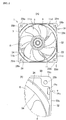
- Fig. 1 is a perspective front view of an axial flow fan according to an embodiment of the present invention.
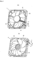
- Fig. 2 is the same view of Fig. 1 except that lead wires are omitted.
- Fig. 3(A) is a font view of the axial flow fan of Fig. 2
- Fig. 3(B) is a partially enlarged view of Fig. 3(A) .
- Fig. 4(A) is a right side view of Fig. 3(A)
- Fig. 4(B) is a partially enlarged view of Fig. 4(A) .
- Fig. 5(A) is a rear view of Fig. 3(A)
- Fig. 5(B) is a partially enlarged view of Fig.
- reference numeral 1 denotes an axial flow fan.
- the axial flow fan 1 includes a fan housing 3, an impeller 5, a motor, not illustrated, including a rotor 7 and a stator, not illustrated, a motor casing 9, a plurality of webs 11 (four webs 11a to 11d), a groove portion 13, a plurality of lead wires 15, a first lead wire engaging portion 17, and a second lead wire engaging portion 19.
- the fan housing 3 includes a first flange 21, a second flange 23, and a cylindrical portion 25.
- the first flange 21 is formed in an annular shape, provided on one side in an axial direction of a not-illustrated rotary shaft of the axial flow fan, that is, on a side where an after-mentioned discharge port is positioned.
- the first flange 21 has a substantially quadrangular outline shape as seen in the axial direction, that is, as viewed from the front of the axial flow fan 1.
- the first flange 21 has an approximately circular discharge opening 22 that defines a discharge port of the axial flow fan 1.
- the first flange 21 includes four flat surfaces 21a on the four corner portions thereof, each having a through-hole 21b through which a fixing screw, not illustrated, is threaded.
- the second flange 23 is formed in an annular shape on the other side in the axial direction, that is, a side where an after-mentioned suction port is positioned.
- a taper portion 21c is formed to slope down to the cylindrical portion 25 in a portion of the first flange 21 where an air channel 25 is defined.
- Eight stationary blades 21d are formed in the taper portion 21c at given intervals in a direction of rotation of the impeller.
- the second flange 23 has a substantially quadrangular outline shape as seen in the axial direction of Fig. 5A , that is, as viewed from the rear of the axial flow fan 1.
- the second flange 23 has an approximately circular suction opening 24 that defines a suction port of the axial flow fan 1.
- the second flange 23 also includes four flat surfaces 23a on the four corner portions thereof, each having a through-hole 23b through which a not-illustrated fixing screw is threaded.
- the cylindrical portion 25 is provided between the first flange 21 and the second flange 23.
- the fan housing 3 has an air channel 26 defined by an inner space IS formed by the first flange 21, the second flange 23 and the cylindrical portion 25.
- the air channel 26 has a suction port or the suction opening 24 and a discharge port or the discharge opening 22.
- a side where the first flange 2 of the fan housing 3 is positioned defines a side where the discharge port or the discharge opening 22 of the axial flow fan 1 is positioned.
- a side where the second flange 23 of the fan housing 3 is positioned defines a side where the suction port or the suction opening 24 of the axial flow fan 1 is positioned.
- positioning of the suction port or the suction opening 24 and a discharge port or the discharge opening 22 are not limited to the configuration of the present embodiment.
- a side where the first flange is positioned may define a side where the suction port or the suction opening 24 of the axial flow fan 1 is positioned.
- a side where the second flange is positioned may define a side where the discharge port or the discharge opening 22 of the axial flow fan 1 is positioned.
- the impeller 5 including a plurality of blades 6 is disposed inside the air channel 26.
- the impeller 5 is fixed to the rotor 7 operable to rotate about the rotary shaft, not illustrated.
- the impeller 5 is rotated inside the air channel 26 by the rotation of the rotor 7 driven by a not-illustrated motor.
- a not-illustrated stator is provided with respect to the rotor 7.
- the not-illustrated motor is received inside a motor casing 9 which includes a bottom wall portion 9a located within the first flange 21 and a peripheral wall portion 9b that is formed continuous with the bottom wall portion 9a and extend toward the suction port or the suction opening 24.
- the plurality of webs 11 are constituted from four webs 11a to 11d.
- the four webs 11a to 11d are disposed within the air channel 26 at intervals in the direction of rotation of the impeller 5 so as to connect the motor casing 9 and the first flange 21.
- One of the four webs 11a to 11d, that is, the web 11d has a groove portion 13 formed therein.
- the groove portion 13 communicates with an internal space of the motor casing 9 and also with a space outside the fan housing 3.
- the groove portion 13 provided in the web 11d receives a plurality of lead wires 15, which are connected to a power supply circuit of the not-illustrated motor and extend toward a space outside the fan housing 3. Refer to Fig. 1 .
- a first lead wire engaging portion 17 is formed in a connecting portion 21e between the first flange 21 and the web 11d.
- the first lead wire engaging portion 27 is configured to allow the plurality of lead wires 15 to be engaged therewith and pulled out therefrom to an outer space OS defined between the first flange 21 and the second flange 23 of the fan housing 3.
- the second lead wire engaging portion 19 is formed in the second flange 23 and configured to allow the plurality of lead wires 15, which have been engaged with the first lead wire engaging portion 17 and pulled out into the outer space OS, to be engaged with the second lead wire engaging portion 19 and then pulled out toward the other side in the axial direction where the second flange 23 is positioned, that is, a side where the suction port is positioned.
- the axial flow fan 1 further includes a third lead wire engaging portion 27 in addition to the first and second lead wire engaging portions 17 and 19.
- the third lead wire engaging portion 27 is configured to allow the plurality of lead wires 15, which have been engaged with the first lead wire engaging portion 17 and pulled out to the outer space OS, to be engaged with the third lead wire engaging portion 27 and then pulled out therefrom in the axial direction toward the one side where the first flange 21 is positioned, that is, a side where the discharge port is positioned.
- the third lead wire engaging portion 27 is formed in the first flange 21 at a given distance from the first lead wire engaging portion 17. The distance between the first lead wire engaging portion 17 and the third lead wire engaging portion 27 may arbitrarily be determined.
- the third lead wire engaging portion 27 is formed in addition to the first and second lead wire engaging portions 17 and 19, it becomes possible to pull out the plurality of lead wires 15 not only toward the side where the second flange 23 is positioned, that is, the side in the axial direction of the fan where the suction port is positioned but also toward the side where the first flange 21 is positioned, that is, the side in the axial direction of the fan where the discharge port is positioned.
- This allows for a wide range of selection for placement of the axial flow fan 1 and wiring of the lead wires 15.
- the presence of the third lead wire engaging portion 27 makes it possible to pull out the plurality of lead wires 15 toward the side in the axial direction where the discharge port or the discharge opening 22 is positioned.
- the second lead wire engaging portion 19 is formed in the second flange 23 and the third lead wire engaging portion 27 is formed in the first flange 21 to face each other in the axial direction.
- the following effects may be obtained when two axial flow fans of the same shape are used by arranging them in the axial direction.
- one of the axial flow fans is designated at 1 and the other axial flow fan is designated at 1'.
- Those components of the other axial flow fan 1' which are common to those of the axial flow fan 1 are designated with the same reference numerals suffixed by an apostrophe (').
- the two axial flow fans 1 and 1' are used by arranging them in the axial direction such that the second flange 23 of the one axial flow fan 1 and the first flange 21' of the other axial flow fan 1' are adjacent to each other, the second lead wire engaging portion 19 formed on the side where the suction port or the suction opening 24 of the axial flow fan 1 is positioned and the third lead wire engaging portion 27' formed on the side where the discharge port or the discharge opening 22' of the other axial flow fan 1' is positioned are adjacent to each other in the axial direction.
- the plurality of lead wires 15, which are engaged with the second lead wire engaging portion 19 provided on the side of the suction port of the axial flow fan 1 may be engaged with the third lead wire engaging portion 27' provided on the side of the discharge port of the other axial flow fan 1' adjacent to the one axial flow fan 1 and also engaged with the second lead wire engaging portion 19' provided on the side of the suction port of the axial flow fan 1'. Accordingly, the plurality of lead wires 15 of the axial flow fan 1 may be pulled out in the axial direction toward the side of the suction port or the suction opening 24' of the other axial flow fan 1' through the third and the second lead wire engaging portions 27' and 19' of the other axial flow fan 1'. Refer to Fig. 6 .
- the plurality of lead wires 15', which are engaged with the third lead wire engaging portion 27' on the side of the discharge port of the other axial flow fan 1' may be engaged with the second lead wire engaging portion 19 provided on the side of the suction port of the axial flow fan 1 adjacent to the discharge port of the other axial flow fan 1', and engaged with the third lead wire engaging portion 27 provided on the side of the discharge port of the one axial flow fan 1. Accordingly, the plurality of lead wires 15' of the other axial flow fan 1' may be pulled out in the axial direction toward the side of the discharge port or the discharge opening 22 of the axial flow fan 1 through the second and third lead wire engaging portions 19 and 27 of the axial flow fan 1. Refer to Fig. 7 .
- the plurality of lead wires 15 may securely be pulled out on either side of the axial direction toward a space outside the suction port or toward a space outside the discharge port.
- the first flange 21 and the second flange 23 has a substantially quadrangular outline shape as seen in the axial direction.
- the first and the third lead wire engaging portions 17 and 27 are formed in one side S1 of the quadrangular outline of the first flange 21.
- the second lead wire engaging portion 19 is formed in one side S2 of the quadrangular outline of the second flange 23, opposed to the side S1 where the first and the third lead wire engaging portions 17 and 27 are formed.
- the third lead wire engaging portion 27 may be provided in the same side S1 of the first flange 21 in the vicinity of the first lead wire engaging portion 17.
- the lead wire 15 need not be longer than necessary even when the lead wire 15 is to be pulled out in the axial direction toward a side where the discharge port is positioned. Further, since the second lead wire engaging portion 19 and the third lead wire engaging portion 27 are arranged along the axial direction, the lead wire 15 need not be longer than necessary even when a plurality of axial flow fans of the same shape are used by arranging them in the axial direction.
- the first lead wire engaging portion 17 may be constituted from a first through-hole 17a that is formed in the first flange 21 to pass therethrough in the axial direction and to communicate with the groove portion 13 of the web 11d, and a first slit 17b that is formed in the first flange 21 to communicate with the first through-hole 17a, passing through the first flange 21 in the axial direction, and opened in an outer peripheral surface 21f of the first flange 21.
- the second lead wire engaging portion 19 may be constituted from a second through-hole 19a that is formed in the second flange 23 to pass therethrough in the axial direction, and a second slit 19b that is formed in the second flange to communicate with the second through-hole 19a, passing through the second flange 23 in the axial direction, and opened to an outer peripheral surface 23c of the second flange 23.
- the third lead wire engaging portion 27 may be constituted from a third through-hole 27a, which is formed in a portion 21g of the first flange 21 that is opposed in the axial direction to the second lead wire engaging portion 19 provided in the second flange 23 and passes through the first flange 21 in the axial direction, and a third slit 27b formed in the first flange 21 to communicate with the third though-hole 27a, passing through the first flange 21 in the axial direction, and opened to an outer peripheral surface 21f of the first flange 21.
- the first slit 17b may be dimensioned so that the plurality of lead wires 15 engaged with the first lead wire engaging portion 17 and passing through the first through-hole 17a may not readily come off from the first slit 17b.
- the second slit 19b may be dimensioned so that the plurality of lead wires 15 engaged with the second lead wire engaging portion 19 and passing through the second through-hole 19a may not readily come off form the second slit 19b.
- the third slit 27b may be dimensioned so that the plurality of lead wires 15 engaged with the third lead wire engaging portion 27 and passing through the third through-hole 27a may not readily come off from the third slit 27b.
- the first through-hole 17a is a trapezoidal hole as viewed from the side where the first flange 21 is positioned, that is, as viewed from the front of the axial flow fan 1, passing in the axial direction through the portion 21e of the first flange 21.
- the width of the first slit 17b in an extending direction of the side S1 of the first flange 21 where the portion 21e is provided is smaller than the width of the through-hole 17a.
- the second through-hole 19a is an elliptical hole in shape with its major axis extending in parallel with an extending direction of the side S2 of the second flange 23.
- the width of the second slit 19b in the extending direction of the side S2 of the second flange 23 is smaller than the width of the major axis of the second through-hole 19a.
- the third through-hole 27a is an elliptical hole with its major axis extending in parallel with the extending direction of the side S1 of the first flange 21.
- the width of the third slit 27b in the extending direction of the side S1 of the first flange 21 is smaller than the width of the major axis of the third through-hole 27a.
- Configurations of the first, second and third through-holes 17a, 19a and 27a are not limited to those employed in the present embodiment, and may arbitrarily be determined as long as the lead wires 15 may not readily come off from the slits 17b, 19b and 27b.
- the plurality of lead wires 15 may be engaged with the first lead wire engaging portion 17, the second lead wire engaging portion 19, and the third wire engaging portion 27 merely by inserting the plurality of lead wires 15 through the first slit 17b, the second slit 19b and the third slit 27b into the first through-hole 17a, the second through-hole 19a and the third through-hole 27a respectively.
- engagement of the plurality of lead wires 15 may be simplified.
- the lead wires 15 may securely be engaged with the first to third lead wire engaging portions 17, 19, 27 since the lead wires 15 do not readily come off from the first to third slits 17b, 19b, 27b.
- Figs. 6 and 7 explain engagement of the plurality of lead wires 15 in the axial flow fan 1 according to the present embodiment.
- the plurality of lead wires 15 received in the groove portion 13 of the web 11d are inserted through the slit 17b into the first through-hole 17a.
- the plurality of lead wires 15 are pulled out into the outer space OS while being engaged with the first lead wire engaging portion 17.
- the plurality of lead wires 15 pulled out into the outer space OS are inserted through the second slit 19b into the second through-hole 19a.
- the plurality of lead wires 15 are engaged with the second lead wire engaging portion 19 while being engaged with the first lead wire engaging portion 17.
- the plurality of lead wires 15 are pulled out in the axial direction toward a side where the suction port or the suction opening 24 is positioned, and then into a space outside the axial flow fan 1.
- the process is similar to that of Fig. 6 until the wires have been engaged with the first lead wire engaging portion 17 and pulled out into the outer space OS. Then, the plurality of lead wires 15 pulled out into the outer space OS are inserted through the third slit 27b into the third through-hole 27a. In this manner, the plurality of lead wires 15 are engaged with the third lead wire engaging portion 27 while being engaged with the first lead wire engaging portion 17 and thereafter pulled out in the axial direction toward a space outside the discharge port or the discharge opening 22 of the axial flow fan 1.
- the engagement of the lead wires 15 is not limited to those shown in Figs. 6 and 7 , and it is a matter of course that the plurality of lead wires 15 may be engaged with the second lead wire engaging portion 19 and the third lead wire engaging portion 27. That is, the plurality of lead wires 15 may be divided and separately pulled out in the axial direction toward both sides where the suction port is positioned and the discharge port is positioned.
- a third lead wire engaging portion is provided in the first flange at a given distance from the first lead wire engaging portion so that a plurality of lead wires pulled out into an outer space between the first flange and the second flange may be engaged with the third lead wire engaging portion and then pulled out toward one side in the axial direction where the first flange is positioned. Accordingly, the lead wires may be pulled out not only to a side where the second flange is positioned but also to a side where the first flange is positioned. Thus, there are many options available how to install or place an axial flow fan and how to guide the lead wires.
Landscapes
- Engineering & Computer Science (AREA)
- Mechanical Engineering (AREA)
- General Engineering & Computer Science (AREA)
- Structures Of Non-Positive Displacement Pumps (AREA)
Claims (4)
- Axialer Lüfter mit:einem Lüftergehäuse (3) aufweisend:einen ersten Flansch (21), welcher auf einer Seite einer Drehwelle in einer axialen Richtung der Drehwelle positioniert ist;einen zweiten Flansch (23), welcher auf der anderen Seite der Drehwelle in axialer Richtung positioiniert ist; undeinen zylindrischen Bereich (25), welcher zwischen dem ersten Flansch und dem zweiten Flansch vorgesehen ist,wobei das Lüftergehäuse einen Luftkanal (26) hat, der durch einen inneren Raum (IS) definiert ist, welcher durch den ersten Flansch, den zweiten Flansch und den zylindrischen Bereich ausgebildet ist, wobei der Luftkanal eine Ansaugöffnung und eine Abgabeöffnung hat;ein Flügelrad, welches in dem Luftkanal positioniert ist und eine Vielzahl von Flügeln (6) aufweist;einen Motor, aufweisend:eine Schaltung zur Energieversorgung;einen Rotor (7), an dem das Flügelrad fixiert ist, welcher eingerichtet ist, um die Drehwelle zu rotieren; undeinen Stator, welcher in Bezug auf den Rotor vorgesehen ist;ein Motorgehäuse (9) zum Aufnehmen des Motors darin, mit einem unteren Wandbereich (9a), der innerhalb des ersten Flansches lokalisiert ist und einen Umfangswandbereich (9b), der kontinuierlich mit dem unteren Wandbereich ausgebildet ist und welcher sich in Richtung des zweiten Flansches erstreckt;eine Vielzahl von Stegen (11), welche in Intervallen in einer Rotationsrichtung des Flügelrades angeordnet sind und innerhalb des Luftkanals lokalisiert sind, um das Motorgehäuse und den ersten Flansch zu verbinden, wobei ein Nutbereich 13 in einem (11 d) der Vielzahl von Stegen ausgebildet ist, um es zu ermöglichen, dass ein innerer Raum des Motorgehäuses in Kommunikation mit einem Raum außerhalb des Lüftergehäuses (3) ist;eine Vielzahl von Leitungsdrähten (15), welche in dem Nutbereich aufgenommen sind, der in einem der Stege ausgebildet ist, welche mit der Schaltung zur Energieversorgung des Motors verbunden sind und sich in Richtung des Raumes außerhalb des Lüftergehäuses (3) erstrecken;einen ersten Eingriffsbereich (17) für Leitungsdrähte, welcher in einem Verbindungsbereich zwischen dem ersten Flansch (21) und dem einen (11 d) der Stege, welche in Eingriff mit der Vielzahl der Leitungsdrähte (15) sind, ausgebildet ist, so dass die Leitungsdrähte von dem ersten Eingriffsbereich (17) für Leitungsdrähte herausgezogen werden in einen äußeren Raum (OS), der zwischen dem ersten Flansch (21) und dem zweiten Flansch (23) des Lüftergehäuses (3) definiert ist und außerhalb des zylindrischen Bereiches (25) des Lüftergehäuses (3) lokalisiert ist; undeinen zweiten Eingriffsbereich (19) für Leitungsdrähte, welcher in dem zweiten Flansch (23) ausgebildet ist, um in Eingriff mit der Vielzahl der Leitungsdrähte (15) zu sein, so dass die Vielzahl der Leitungsdrähte, welche in Eingriff mit dem ersten Eingriffsbereich (17) für Leitungsdrähte und davon herausgezogen in den äußeren Raum (OS) sind, dann herausgezogen in Richtung der äußeren Seite der Drehwelle in Axialrichtung, wo der zweite Flansch (23) positioniert ist,dadurch gekennzeichnet,dass der Axiallüfter des Weiteren aufweist:
einen dritten Eingriffsbereich (27) für Leitungsdrähte, welcher in dem ersten Flansch (21) in einem vorbestimmten Abstand von dem ersten Eingriffsbereich (17) für Leitungsdrähte ausgebildet ist, um mit der Vielzahl von Leitungsdrähten (15) in Eingriff zu stehen, so dass die Leitungsdrähte, welche von dem ersten Eingriffsbereich für Leitungsdrähte in den äußeren Raum gezogen sind, dann auswärts zu einer Seite in die axiale Richtung gezogen werden, wo der erste Flansch (21) positioniert ist. - Axiallüfter nach Anspruch 1,
wobei der zweite Eingriffsbereich (19) für Leitungsdrähte, welcher in dem zweiten Flansch (23) ausgebildet ist und der dritte Eingriffsbereich (27) für Leitungsdrähte, welch in dem ersten Flansch (21) ausgebildet ist, in axialer Richtung gegenüberliegend sind. - Axiallüfter nach Anspruch 1, wobei:der erste Flansch (21) und der zweite Flansch (23) jeder eine im Wesentlichen viereckige Umrissform, gesehen in der Axialrichtung hat; undder erste Eingriffsbereich (17) für Leitungsdrähte und der dritte Eingriffsbereich (27) für Leitungsdrähte auf einer Seite (S1) der viereckigen Umrissform des ersten Flansches (21) ausgebildet sind; undder zweite Eingriffsbereich (19) für Leitungsdrähte in einer Seite (S2) des zweiten Flansches (23) gegenüberliegend der einen Seite der viereckigen Umrissform des ersten Flansches (21), an der die ersten und dritten Eingriffsbereiche (17, 27) für Leitungsdrähte ausgebildet sind, ausgebildet ist.
- Axiallüfter nach einem der Ansprüche 1 bis 3, wobei:der erste Eingriffsbereich (17) für Leitungsdraht aus einem ersten Durchgangsloch (17a), welches in dem ersten Flansch (21) ausgebildet ist, um dorthin in der axialen Richtung zu gehen und in Verbindung mit dem Nutbereich (13) des einen (11 d) der Stege und einem ersten Schlitz (17b), welcher in dem ersten Flansch (21) ausgebildet ist, um mit dem ersten Durchgangsloch (17a) in Verbindung zu sein, welches den ersten Flansch (21) in axialer Richtung durchquert, gebildet ist, und geöffnet in einer äußeren Umfangsfläche (21f) des ersten Flansches (21) ist;der zweite Eingriffsbereich (17) für Leitungsdraht aus einem zweiten Durchgangsloch (19a), welches in dem zweiten Flansch (23) ausgebildet ist, um dorthin in der axialen Richtung zu gehen und einem zweiten Schlitz (19b), welcher in dem zweiten Flansch (23) ausgebildet ist, um mit dem zweiten Durchgangsloch (19b) in Verbindung zu sein, welches den zweiten Flansch (23) in axialer Richtung durchquert, gebildet ist, und geöffnet in einer äußeren Umfangsfläche (23c) des zweiten Flansches (23) ist;der dritte Eingriffsbereich (27) für Leitungsdraht aus einem dritten Durchgangsloch (27a), welches in dem ersten Flansch (21) ausgebildet ist, um dorthin in der axialen Richtung zu gehen und einem dritten Schlitz (27b), welcher in dem ersten Flansch (21) ausgebildet ist, um mit dem dritten Durchgangsloch (27a) in Verbindung zu sein, welches den ersten Flansch (21) in axialer Richtung durchquert, gebildet ist, und geöffnet in einer äußeren Umfangsfläche des ersten Flansches (21) ist;der erste Schlitz (17) so dimensioniert ist, dass die Vielzahl von Leitungsdrähten (15), welche in Eingriff mit dem ersten Eingriffsbereich (17) für Leitungsdrähte sind und durch das erste Durchgangsloch (17a) hindurchgehen, nicht ohne Weiteres aus dem ersten Schlitz (17) herauskommen;der zweite Schlitz (19b) so dimensioniert ist, dass die Vielzahl von Leitungsdrähten (15), welche in Eingriff mit dem zweiten Eingriffsbereich (19) für Leitungsdrähte sind und durch das zweite Durchgangsloch (19a) hindurchgehen, nicht ohne Weiteres aus dem zweiten Schlitz (19b) herauskommen;der dritte Schlitz (27b) so dimensioniert ist, dass die Vielzahl von Leitungsdrähten (15), welche in Eingriff mit dem dritten Eingriffsbereich (27) für Leitungsdrähte sind und durch das dritte Durchgangsloch (27a) hindurchgehen, nicht ohne Weiteres aus dem dritten Schlitz (27b) herauskommen.
Applications Claiming Priority (2)
| Application Number | Priority Date | Filing Date | Title |
|---|---|---|---|
| JP2008167032A JP5129667B2 (ja) | 2008-06-26 | 2008-06-26 | 軸流送風機 |
| PCT/JP2009/060903 WO2009157338A1 (ja) | 2008-06-26 | 2009-06-15 | 軸流送風機 |
Publications (3)
| Publication Number | Publication Date |
|---|---|
| EP2317149A1 EP2317149A1 (de) | 2011-05-04 |
| EP2317149A4 EP2317149A4 (de) | 2015-03-25 |
| EP2317149B1 true EP2317149B1 (de) | 2018-05-16 |
Family
ID=41444406
Family Applications (1)
| Application Number | Title | Priority Date | Filing Date |
|---|---|---|---|
| EP09770048.8A Active EP2317149B1 (de) | 2008-06-26 | 2009-06-15 | Axialgebläse |
Country Status (6)
| Country | Link |
|---|---|
| US (2) | US8616864B2 (de) |
| EP (1) | EP2317149B1 (de) |
| JP (1) | JP5129667B2 (de) |
| CN (1) | CN102066763B (de) |
| TW (1) | TWI465645B (de) |
| WO (1) | WO2009157338A1 (de) |
Families Citing this family (21)
| Publication number | Priority date | Publication date | Assignee | Title |
|---|---|---|---|---|
| JP5129667B2 (ja) * | 2008-06-26 | 2013-01-30 | 山洋電気株式会社 | 軸流送風機 |
| US8684708B2 (en) * | 2009-12-16 | 2014-04-01 | Asia Vital Components Co., Ltd. | Fan stator cover structure |
| JP5739200B2 (ja) * | 2010-04-20 | 2015-06-24 | 山洋電気株式会社 | 送風機 |
| JP5702981B2 (ja) | 2010-10-07 | 2015-04-15 | 山洋電気株式会社 | リード線係止構造及び電気機器 |
| CN103511345B (zh) * | 2012-06-29 | 2016-04-06 | 台达电子工业股份有限公司 | 具有理线结构的扇框 |
| CN104251216A (zh) * | 2013-06-28 | 2014-12-31 | 技嘉科技股份有限公司 | 风扇、扇框及其风扇装置 |
| USD732655S1 (en) * | 2013-11-21 | 2015-06-23 | Sanyo Denki Co., Ltd. | Fan |
| USD723151S1 (en) * | 2013-12-13 | 2015-02-24 | Cooler Master Co., Ltd. | Fan |
| CN104948476B (zh) * | 2014-03-31 | 2020-06-02 | 台达电子工业股份有限公司 | 薄型风扇、电子系统及薄型风扇的制造方法 |
| JP2017184433A (ja) | 2016-03-30 | 2017-10-05 | 日本電産株式会社 | ファンモータ |
| US20180023578A1 (en) * | 2016-07-21 | 2018-01-25 | Denso International America, Inc. | Fan shroud, fan device, and manufacturing process |
| US11884128B2 (en) | 2017-12-18 | 2024-01-30 | Carrier Corporation | Fan stator construction to minimize axial depth |
| USD911512S1 (en) | 2018-01-31 | 2021-02-23 | Carrier Corporation | Axial flow fan |
| DE102018211808A1 (de) * | 2018-07-16 | 2020-01-16 | Ziehl-Abegg Se | Ventilator und Leiteinrichtung für einen Ventilator |
| TWI782292B (zh) * | 2020-07-03 | 2022-11-01 | 大陸商奇宏電子(深圳)有限公司 | 風扇框體結構 |
| CN111828394A (zh) * | 2020-07-03 | 2020-10-27 | 奇宏电子(深圳)有限公司 | 风扇框体结构 |
| JP7634421B2 (ja) * | 2021-05-12 | 2025-02-21 | 山洋電気株式会社 | リバーシブルファン |
| JP7633878B2 (ja) | 2021-05-12 | 2025-02-20 | 山洋電気株式会社 | リバーシブルファン |
| USD1041636S1 (en) * | 2021-05-25 | 2024-09-10 | Sea Sonic Electronics Co., Ltd. | Magnetic fan |
| CN115995908A (zh) * | 2021-10-19 | 2023-04-21 | 日本电产株式会社 | 马达及轴流风扇 |
| CN115342074B (zh) * | 2022-08-11 | 2024-03-15 | 深圳市永亿豪电子有限公司 | 一种组合风扇结构 |
Family Cites Families (14)
| Publication number | Priority date | Publication date | Assignee | Title |
|---|---|---|---|---|
| JPS6117500U (ja) * | 1984-07-06 | 1986-01-31 | 三洋電機株式会社 | 送風機 |
| JPH1172098A (ja) * | 1998-07-16 | 1999-03-16 | Seiko Epson Corp | 軸流送風機 |
| JP3465104B2 (ja) * | 1998-08-18 | 2003-11-10 | ミネベア株式会社 | 軸流送風機 |
| TW502821U (en) * | 1999-10-20 | 2002-09-11 | Delta Electronics Inc | Wire arranging structure for fan |
| JP2002039091A (ja) * | 2000-07-21 | 2002-02-06 | Minebea Co Ltd | 送風機 |
| JP2005256749A (ja) * | 2004-03-12 | 2005-09-22 | Nippon Densan Corp | ファン |
| DE502006005443D1 (de) * | 2005-08-19 | 2010-01-07 | Ebm Papst St Georgen Gmbh & Co | Lüfter |
| TWM291192U (en) * | 2005-12-13 | 2006-05-21 | Delta Electronics Inc | Fan housing and wire collection structure thereof |
| CN2886153Y (zh) * | 2005-12-27 | 2007-04-04 | 台达电子工业股份有限公司 | 扇框及其理线构件 |
| JP4871189B2 (ja) * | 2006-04-18 | 2012-02-08 | 山洋電気株式会社 | 軸流送風機 |
| JP4844877B2 (ja) * | 2006-05-29 | 2011-12-28 | 日本電産株式会社 | 直列式軸流ファンおよび軸流ファン |
| TWI355878B (en) * | 2006-12-26 | 2012-01-01 | Sunonwealth Electr Mach Ind Co | Heat-dissipating fan having wire-positioning struc |
| CN101382151B (zh) * | 2007-09-07 | 2010-05-26 | 富准精密工业(深圳)有限公司 | 风扇扇框 |
| JP5129667B2 (ja) * | 2008-06-26 | 2013-01-30 | 山洋電気株式会社 | 軸流送風機 |
-
2008
- 2008-06-26 JP JP2008167032A patent/JP5129667B2/ja active Active
-
2009
- 2009-06-15 WO PCT/JP2009/060903 patent/WO2009157338A1/ja not_active Ceased
- 2009-06-15 CN CN200980124016.0A patent/CN102066763B/zh active Active
- 2009-06-15 US US13/001,503 patent/US8616864B2/en active Active
- 2009-06-15 EP EP09770048.8A patent/EP2317149B1/de active Active
- 2009-06-24 TW TW098121191A patent/TWI465645B/zh active
-
2013
- 2013-11-04 US US14/070,719 patent/US9145896B2/en active Active
Non-Patent Citations (1)
| Title |
|---|
| None * |
Also Published As
| Publication number | Publication date |
|---|---|
| CN102066763A (zh) | 2011-05-18 |
| JP5129667B2 (ja) | 2013-01-30 |
| JP2010007545A (ja) | 2010-01-14 |
| WO2009157338A1 (ja) | 2009-12-30 |
| US20110097226A1 (en) | 2011-04-28 |
| US8616864B2 (en) | 2013-12-31 |
| US20140056742A1 (en) | 2014-02-27 |
| EP2317149A4 (de) | 2015-03-25 |
| EP2317149A1 (de) | 2011-05-04 |
| TW201016980A (en) | 2010-05-01 |
| CN102066763B (zh) | 2014-01-22 |
| TWI465645B (zh) | 2014-12-21 |
| US9145896B2 (en) | 2015-09-29 |
Similar Documents
| Publication | Publication Date | Title |
|---|---|---|
| EP2317149B1 (de) | Axialgebläse | |
| EP2886871B1 (de) | Wasserdichter Axialstromlüfter | |
| US20140105763A1 (en) | Axial-flow fan | |
| US7800263B2 (en) | Heat dissipating fan | |
| EP2381111B1 (de) | Lüfter mit verringertem Lärm | |
| US20130164158A1 (en) | Centrifugal fan | |
| US10113551B2 (en) | Axial flow fan | |
| JP2009144519A (ja) | 直列式軸流ファン | |
| CN1987122A (zh) | 轴流式风扇 | |
| JP6504754B2 (ja) | 電動送風機およびそれを用いた電気掃除機 | |
| JP2019180195A (ja) | モータ、遠心ファン | |
| US7762767B2 (en) | Axial-flow fan | |
| JP2015068347A (ja) | 遠心インペラ及び遠心ブロワ | |
| KR20150015271A (ko) | 전동 송풍기용 원심 팬 | |
| JP4469736B2 (ja) | 軸流送風機 | |
| JP2008115696A (ja) | ファン装置 | |
| KR102686935B1 (ko) | 전동공구 | |
| JP2008196504A (ja) | 軸流送風機 | |
| KR102537327B1 (ko) | 송풍팬 | |
| JP2019088190A (ja) | 電動送風機およびそれを用いた電気掃除機 | |
| JP2000333410A (ja) | 回転電機 | |
| HK1112044B (en) | Axial flow blower |
Legal Events
| Date | Code | Title | Description |
|---|---|---|---|
| PUAI | Public reference made under article 153(3) epc to a published international application that has entered the european phase |
Free format text: ORIGINAL CODE: 0009012 |
|
| 17P | Request for examination filed |
Effective date: 20101230 |
|
| AK | Designated contracting states |
Kind code of ref document: A1 Designated state(s): AT BE BG CH CY CZ DE DK EE ES FI FR GB GR HR HU IE IS IT LI LT LU LV MC MK MT NL NO PL PT RO SE SI SK TR |
|
| AX | Request for extension of the european patent |
Extension state: AL BA RS |
|
| DAX | Request for extension of the european patent (deleted) | ||
| A4 | Supplementary search report drawn up and despatched |
Effective date: 20150219 |
|
| RIC1 | Information provided on ipc code assigned before grant |
Ipc: F04D 25/08 20060101AFI20150213BHEP Ipc: F04D 25/06 20060101ALI20150213BHEP Ipc: F04D 29/52 20060101ALI20150213BHEP |
|
| STAA | Information on the status of an ep patent application or granted ep patent |
Free format text: STATUS: EXAMINATION IS IN PROGRESS |
|
| 17Q | First examination report despatched |
Effective date: 20161221 |
|
| GRAP | Despatch of communication of intention to grant a patent |
Free format text: ORIGINAL CODE: EPIDOSNIGR1 |
|
| STAA | Information on the status of an ep patent application or granted ep patent |
Free format text: STATUS: GRANT OF PATENT IS INTENDED |
|
| INTG | Intention to grant announced |
Effective date: 20171211 |
|
| GRAJ | Information related to disapproval of communication of intention to grant by the applicant or resumption of examination proceedings by the epo deleted |
Free format text: ORIGINAL CODE: EPIDOSDIGR1 |
|
| STAA | Information on the status of an ep patent application or granted ep patent |
Free format text: STATUS: EXAMINATION IS IN PROGRESS |
|
| GRAP | Despatch of communication of intention to grant a patent |
Free format text: ORIGINAL CODE: EPIDOSNIGR1 |
|
| STAA | Information on the status of an ep patent application or granted ep patent |
Free format text: STATUS: GRANT OF PATENT IS INTENDED |
|
| GRAS | Grant fee paid |
Free format text: ORIGINAL CODE: EPIDOSNIGR3 |
|
| GRAA | (expected) grant |
Free format text: ORIGINAL CODE: 0009210 |
|
| STAA | Information on the status of an ep patent application or granted ep patent |
Free format text: STATUS: THE PATENT HAS BEEN GRANTED |
|
| INTC | Intention to grant announced (deleted) | ||
| INTG | Intention to grant announced |
Effective date: 20180327 |
|
| AK | Designated contracting states |
Kind code of ref document: B1 Designated state(s): AT BE BG CH CY CZ DE DK EE ES FI FR GB GR HR HU IE IS IT LI LT LU LV MC MK MT NL NO PL PT RO SE SI SK TR |
|
| REG | Reference to a national code |
Ref country code: GB Ref legal event code: FG4D |
|
| REG | Reference to a national code |
Ref country code: CH Ref legal event code: EP |
|
| REG | Reference to a national code |
Ref country code: DE Ref legal event code: R096 Ref document number: 602009052334 Country of ref document: DE |
|
| REG | Reference to a national code |
Ref country code: IE Ref legal event code: FG4D |
|
| REG | Reference to a national code |
Ref country code: AT Ref legal event code: REF Ref document number: 999851 Country of ref document: AT Kind code of ref document: T Effective date: 20180615 |
|
| REG | Reference to a national code |
Ref country code: FR Ref legal event code: PLFP Year of fee payment: 10 |
|
| REG | Reference to a national code |
Ref country code: NL Ref legal event code: MP Effective date: 20180516 |
|
| REG | Reference to a national code |
Ref country code: LT Ref legal event code: MG4D |
|
| PG25 | Lapsed in a contracting state [announced via postgrant information from national office to epo] |
Ref country code: ES Free format text: LAPSE BECAUSE OF FAILURE TO SUBMIT A TRANSLATION OF THE DESCRIPTION OR TO PAY THE FEE WITHIN THE PRESCRIBED TIME-LIMIT Effective date: 20180516 Ref country code: LT Free format text: LAPSE BECAUSE OF FAILURE TO SUBMIT A TRANSLATION OF THE DESCRIPTION OR TO PAY THE FEE WITHIN THE PRESCRIBED TIME-LIMIT Effective date: 20180516 Ref country code: FI Free format text: LAPSE BECAUSE OF FAILURE TO SUBMIT A TRANSLATION OF THE DESCRIPTION OR TO PAY THE FEE WITHIN THE PRESCRIBED TIME-LIMIT Effective date: 20180516 Ref country code: BG Free format text: LAPSE BECAUSE OF FAILURE TO SUBMIT A TRANSLATION OF THE DESCRIPTION OR TO PAY THE FEE WITHIN THE PRESCRIBED TIME-LIMIT Effective date: 20180816 Ref country code: NO Free format text: LAPSE BECAUSE OF FAILURE TO SUBMIT A TRANSLATION OF THE DESCRIPTION OR TO PAY THE FEE WITHIN THE PRESCRIBED TIME-LIMIT Effective date: 20180816 Ref country code: SE Free format text: LAPSE BECAUSE OF FAILURE TO SUBMIT A TRANSLATION OF THE DESCRIPTION OR TO PAY THE FEE WITHIN THE PRESCRIBED TIME-LIMIT Effective date: 20180516 |
|
| PG25 | Lapsed in a contracting state [announced via postgrant information from national office to epo] |
Ref country code: GR Free format text: LAPSE BECAUSE OF FAILURE TO SUBMIT A TRANSLATION OF THE DESCRIPTION OR TO PAY THE FEE WITHIN THE PRESCRIBED TIME-LIMIT Effective date: 20180817 Ref country code: HR Free format text: LAPSE BECAUSE OF FAILURE TO SUBMIT A TRANSLATION OF THE DESCRIPTION OR TO PAY THE FEE WITHIN THE PRESCRIBED TIME-LIMIT Effective date: 20180516 Ref country code: LV Free format text: LAPSE BECAUSE OF FAILURE TO SUBMIT A TRANSLATION OF THE DESCRIPTION OR TO PAY THE FEE WITHIN THE PRESCRIBED TIME-LIMIT Effective date: 20180516 Ref country code: NL Free format text: LAPSE BECAUSE OF FAILURE TO SUBMIT A TRANSLATION OF THE DESCRIPTION OR TO PAY THE FEE WITHIN THE PRESCRIBED TIME-LIMIT Effective date: 20180516 |
|
| REG | Reference to a national code |
Ref country code: AT Ref legal event code: MK05 Ref document number: 999851 Country of ref document: AT Kind code of ref document: T Effective date: 20180516 |
|
| PG25 | Lapsed in a contracting state [announced via postgrant information from national office to epo] |
Ref country code: SK Free format text: LAPSE BECAUSE OF FAILURE TO SUBMIT A TRANSLATION OF THE DESCRIPTION OR TO PAY THE FEE WITHIN THE PRESCRIBED TIME-LIMIT Effective date: 20180516 Ref country code: RO Free format text: LAPSE BECAUSE OF FAILURE TO SUBMIT A TRANSLATION OF THE DESCRIPTION OR TO PAY THE FEE WITHIN THE PRESCRIBED TIME-LIMIT Effective date: 20180516 Ref country code: CZ Free format text: LAPSE BECAUSE OF FAILURE TO SUBMIT A TRANSLATION OF THE DESCRIPTION OR TO PAY THE FEE WITHIN THE PRESCRIBED TIME-LIMIT Effective date: 20180516 Ref country code: PL Free format text: LAPSE BECAUSE OF FAILURE TO SUBMIT A TRANSLATION OF THE DESCRIPTION OR TO PAY THE FEE WITHIN THE PRESCRIBED TIME-LIMIT Effective date: 20180516 Ref country code: DK Free format text: LAPSE BECAUSE OF FAILURE TO SUBMIT A TRANSLATION OF THE DESCRIPTION OR TO PAY THE FEE WITHIN THE PRESCRIBED TIME-LIMIT Effective date: 20180516 Ref country code: EE Free format text: LAPSE BECAUSE OF FAILURE TO SUBMIT A TRANSLATION OF THE DESCRIPTION OR TO PAY THE FEE WITHIN THE PRESCRIBED TIME-LIMIT Effective date: 20180516 Ref country code: AT Free format text: LAPSE BECAUSE OF FAILURE TO SUBMIT A TRANSLATION OF THE DESCRIPTION OR TO PAY THE FEE WITHIN THE PRESCRIBED TIME-LIMIT Effective date: 20180516 |
|
| REG | Reference to a national code |
Ref country code: CH Ref legal event code: PL |
|
| REG | Reference to a national code |
Ref country code: DE Ref legal event code: R097 Ref document number: 602009052334 Country of ref document: DE |
|
| PG25 | Lapsed in a contracting state [announced via postgrant information from national office to epo] |
Ref country code: IT Free format text: LAPSE BECAUSE OF FAILURE TO SUBMIT A TRANSLATION OF THE DESCRIPTION OR TO PAY THE FEE WITHIN THE PRESCRIBED TIME-LIMIT Effective date: 20180516 |
|
| REG | Reference to a national code |
Ref country code: BE Ref legal event code: MM Effective date: 20180630 |
|
| REG | Reference to a national code |
Ref country code: IE Ref legal event code: MM4A |
|
| PLBE | No opposition filed within time limit |
Free format text: ORIGINAL CODE: 0009261 |
|
| STAA | Information on the status of an ep patent application or granted ep patent |
Free format text: STATUS: NO OPPOSITION FILED WITHIN TIME LIMIT |
|
| PG25 | Lapsed in a contracting state [announced via postgrant information from national office to epo] |
Ref country code: MC Free format text: LAPSE BECAUSE OF FAILURE TO SUBMIT A TRANSLATION OF THE DESCRIPTION OR TO PAY THE FEE WITHIN THE PRESCRIBED TIME-LIMIT Effective date: 20180516 Ref country code: LU Free format text: LAPSE BECAUSE OF NON-PAYMENT OF DUE FEES Effective date: 20180615 |
|
| 26N | No opposition filed |
Effective date: 20190219 |
|
| PG25 | Lapsed in a contracting state [announced via postgrant information from national office to epo] |
Ref country code: LI Free format text: LAPSE BECAUSE OF NON-PAYMENT OF DUE FEES Effective date: 20180630 Ref country code: CH Free format text: LAPSE BECAUSE OF NON-PAYMENT OF DUE FEES Effective date: 20180630 Ref country code: IE Free format text: LAPSE BECAUSE OF NON-PAYMENT OF DUE FEES Effective date: 20180615 |
|
| PG25 | Lapsed in a contracting state [announced via postgrant information from national office to epo] |
Ref country code: SI Free format text: LAPSE BECAUSE OF FAILURE TO SUBMIT A TRANSLATION OF THE DESCRIPTION OR TO PAY THE FEE WITHIN THE PRESCRIBED TIME-LIMIT Effective date: 20180516 Ref country code: BE Free format text: LAPSE BECAUSE OF NON-PAYMENT OF DUE FEES Effective date: 20180630 |
|
| PG25 | Lapsed in a contracting state [announced via postgrant information from national office to epo] |
Ref country code: MT Free format text: LAPSE BECAUSE OF NON-PAYMENT OF DUE FEES Effective date: 20180615 |
|
| PG25 | Lapsed in a contracting state [announced via postgrant information from national office to epo] |
Ref country code: TR Free format text: LAPSE BECAUSE OF FAILURE TO SUBMIT A TRANSLATION OF THE DESCRIPTION OR TO PAY THE FEE WITHIN THE PRESCRIBED TIME-LIMIT Effective date: 20180516 |
|
| PG25 | Lapsed in a contracting state [announced via postgrant information from national office to epo] |
Ref country code: HU Free format text: LAPSE BECAUSE OF FAILURE TO SUBMIT A TRANSLATION OF THE DESCRIPTION OR TO PAY THE FEE WITHIN THE PRESCRIBED TIME-LIMIT; INVALID AB INITIO Effective date: 20090615 Ref country code: PT Free format text: LAPSE BECAUSE OF FAILURE TO SUBMIT A TRANSLATION OF THE DESCRIPTION OR TO PAY THE FEE WITHIN THE PRESCRIBED TIME-LIMIT Effective date: 20180516 |
|
| PG25 | Lapsed in a contracting state [announced via postgrant information from national office to epo] |
Ref country code: MK Free format text: LAPSE BECAUSE OF NON-PAYMENT OF DUE FEES Effective date: 20180516 Ref country code: CY Free format text: LAPSE BECAUSE OF FAILURE TO SUBMIT A TRANSLATION OF THE DESCRIPTION OR TO PAY THE FEE WITHIN THE PRESCRIBED TIME-LIMIT Effective date: 20180516 |
|
| PG25 | Lapsed in a contracting state [announced via postgrant information from national office to epo] |
Ref country code: IS Free format text: LAPSE BECAUSE OF FAILURE TO SUBMIT A TRANSLATION OF THE DESCRIPTION OR TO PAY THE FEE WITHIN THE PRESCRIBED TIME-LIMIT Effective date: 20180916 |
|
| PGFP | Annual fee paid to national office [announced via postgrant information from national office to epo] |
Ref country code: DE Payment date: 20250618 Year of fee payment: 17 |
|
| PGFP | Annual fee paid to national office [announced via postgrant information from national office to epo] |
Ref country code: GB Payment date: 20250618 Year of fee payment: 17 |
|
| PGFP | Annual fee paid to national office [announced via postgrant information from national office to epo] |
Ref country code: FR Payment date: 20250624 Year of fee payment: 17 |