EP2317253A2 - Vorrichtung mit Kühlmittel und Verfahren zur Installation der Vorrichtung mit dem Kühlmittel - Google Patents
Vorrichtung mit Kühlmittel und Verfahren zur Installation der Vorrichtung mit dem Kühlmittel Download PDFInfo
- Publication number
- EP2317253A2 EP2317253A2 EP10009570A EP10009570A EP2317253A2 EP 2317253 A2 EP2317253 A2 EP 2317253A2 EP 10009570 A EP10009570 A EP 10009570A EP 10009570 A EP10009570 A EP 10009570A EP 2317253 A2 EP2317253 A2 EP 2317253A2
- Authority
- EP
- European Patent Office
- Prior art keywords
- refrigerant
- outdoor unit
- combustible
- unit
- load
- Prior art date
- Legal status (The legal status is an assumption and is not a legal conclusion. Google has not performed a legal analysis and makes no representation as to the accuracy of the status listed.)
- Granted
Links
Images


Classifications
-
- F—MECHANICAL ENGINEERING; LIGHTING; HEATING; WEAPONS; BLASTING
- F25—REFRIGERATION OR COOLING; COMBINED HEATING AND REFRIGERATION SYSTEMS; HEAT PUMP SYSTEMS; MANUFACTURE OR STORAGE OF ICE; LIQUEFACTION SOLIDIFICATION OF GASES
- F25B—REFRIGERATION MACHINES, PLANTS OR SYSTEMS; COMBINED HEATING AND REFRIGERATION SYSTEMS; HEAT PUMP SYSTEMS
- F25B45/00—Arrangements for charging or discharging refrigerant
-
- B—PERFORMING OPERATIONS; TRANSPORTING
- B23—MACHINE TOOLS; METAL-WORKING NOT OTHERWISE PROVIDED FOR
- B23P—METAL-WORKING NOT OTHERWISE PROVIDED FOR; COMBINED OPERATIONS; UNIVERSAL MACHINE TOOLS
- B23P19/00—Machines for simply fitting together or separating metal parts or objects, or metal and non-metal parts, whether or not involving some deformation; Tools or devices therefor so far as not provided for in other classes
- B23P19/04—Machines for simply fitting together or separating metal parts or objects, or metal and non-metal parts, whether or not involving some deformation; Tools or devices therefor so far as not provided for in other classes for assembling or disassembling parts
-
- F—MECHANICAL ENGINEERING; LIGHTING; HEATING; WEAPONS; BLASTING
- F25—REFRIGERATION OR COOLING; COMBINED HEATING AND REFRIGERATION SYSTEMS; HEAT PUMP SYSTEMS; MANUFACTURE OR STORAGE OF ICE; LIQUEFACTION SOLIDIFICATION OF GASES
- F25B—REFRIGERATION MACHINES, PLANTS OR SYSTEMS; COMBINED HEATING AND REFRIGERATION SYSTEMS; HEAT PUMP SYSTEMS
- F25B9/00—Compression machines, plants or systems, in which the refrigerant is air or other gas of low boiling point
- F25B9/002—Compression machines, plants or systems, in which the refrigerant is air or other gas of low boiling point characterised by the refrigerant
-
- F—MECHANICAL ENGINEERING; LIGHTING; HEATING; WEAPONS; BLASTING
- F25—REFRIGERATION OR COOLING; COMBINED HEATING AND REFRIGERATION SYSTEMS; HEAT PUMP SYSTEMS; MANUFACTURE OR STORAGE OF ICE; LIQUEFACTION SOLIDIFICATION OF GASES
- F25B—REFRIGERATION MACHINES, PLANTS OR SYSTEMS; COMBINED HEATING AND REFRIGERATION SYSTEMS; HEAT PUMP SYSTEMS
- F25B13/00—Compression machines, plants or systems, with reversible cycle
-
- F—MECHANICAL ENGINEERING; LIGHTING; HEATING; WEAPONS; BLASTING
- F25—REFRIGERATION OR COOLING; COMBINED HEATING AND REFRIGERATION SYSTEMS; HEAT PUMP SYSTEMS; MANUFACTURE OR STORAGE OF ICE; LIQUEFACTION SOLIDIFICATION OF GASES
- F25B—REFRIGERATION MACHINES, PLANTS OR SYSTEMS; COMBINED HEATING AND REFRIGERATION SYSTEMS; HEAT PUMP SYSTEMS
- F25B2309/00—Gas cycle refrigeration machines
- F25B2309/06—Compression machines, plants or systems characterised by the refrigerant being carbon dioxide
-
- F—MECHANICAL ENGINEERING; LIGHTING; HEATING; WEAPONS; BLASTING
- F25—REFRIGERATION OR COOLING; COMBINED HEATING AND REFRIGERATION SYSTEMS; HEAT PUMP SYSTEMS; MANUFACTURE OR STORAGE OF ICE; LIQUEFACTION SOLIDIFICATION OF GASES
- F25B—REFRIGERATION MACHINES, PLANTS OR SYSTEMS; COMBINED HEATING AND REFRIGERATION SYSTEMS; HEAT PUMP SYSTEMS
- F25B2400/00—Component parts or details not otherwise provided for in this subclass
- F25B2400/12—Inflammable refrigerants
- F25B2400/121—Inflammable refrigerants using R1234
-
- F—MECHANICAL ENGINEERING; LIGHTING; HEATING; WEAPONS; BLASTING
- F25—REFRIGERATION OR COOLING; COMBINED HEATING AND REFRIGERATION SYSTEMS; HEAT PUMP SYSTEMS; MANUFACTURE OR STORAGE OF ICE; LIQUEFACTION SOLIDIFICATION OF GASES
- F25B—REFRIGERATION MACHINES, PLANTS OR SYSTEMS; COMBINED HEATING AND REFRIGERATION SYSTEMS; HEAT PUMP SYSTEMS
- F25B9/00—Compression machines, plants or systems, in which the refrigerant is air or other gas of low boiling point
- F25B9/002—Compression machines, plants or systems, in which the refrigerant is air or other gas of low boiling point characterised by the refrigerant
- F25B9/006—Compression machines, plants or systems, in which the refrigerant is air or other gas of low boiling point characterised by the refrigerant the refrigerant containing more than one component
-
- F—MECHANICAL ENGINEERING; LIGHTING; HEATING; WEAPONS; BLASTING
- F25—REFRIGERATION OR COOLING; COMBINED HEATING AND REFRIGERATION SYSTEMS; HEAT PUMP SYSTEMS; MANUFACTURE OR STORAGE OF ICE; LIQUEFACTION SOLIDIFICATION OF GASES
- F25D—REFRIGERATORS; COLD ROOMS; ICE-BOXES; COOLING OR FREEZING APPARATUS NOT OTHERWISE PROVIDED FOR
- F25D2400/00—General features of, or devices for refrigerators, cold rooms, ice-boxes, or for cooling or freezing apparatus not covered by any other subclass
- F25D2400/32—Removal, transportation or shipping of refrigerating devices from one location to another
-
- Y—GENERAL TAGGING OF NEW TECHNOLOGICAL DEVELOPMENTS; GENERAL TAGGING OF CROSS-SECTIONAL TECHNOLOGIES SPANNING OVER SEVERAL SECTIONS OF THE IPC; TECHNICAL SUBJECTS COVERED BY FORMER USPC CROSS-REFERENCE ART COLLECTIONS [XRACs] AND DIGESTS
- Y02—TECHNOLOGIES OR APPLICATIONS FOR MITIGATION OR ADAPTATION AGAINST CLIMATE CHANGE
- Y02P—CLIMATE CHANGE MITIGATION TECHNOLOGIES IN THE PRODUCTION OR PROCESSING OF GOODS
- Y02P80/00—Climate change mitigation technologies for sector-wide applications
- Y02P80/10—Efficient use of energy, e.g. using compressed air or pressurized fluid as energy carrier
-
- Y—GENERAL TAGGING OF NEW TECHNOLOGICAL DEVELOPMENTS; GENERAL TAGGING OF CROSS-SECTIONAL TECHNOLOGIES SPANNING OVER SEVERAL SECTIONS OF THE IPC; TECHNICAL SUBJECTS COVERED BY FORMER USPC CROSS-REFERENCE ART COLLECTIONS [XRACs] AND DIGESTS
- Y10—TECHNICAL SUBJECTS COVERED BY FORMER USPC
- Y10T—TECHNICAL SUBJECTS COVERED BY FORMER US CLASSIFICATION
- Y10T29/00—Metal working
- Y10T29/49—Method of mechanical manufacture
- Y10T29/4935—Heat exchanger or boiler making
- Y10T29/49359—Cooling apparatus making, e.g., air conditioner, refrigerator
-
- Y—GENERAL TAGGING OF NEW TECHNOLOGICAL DEVELOPMENTS; GENERAL TAGGING OF CROSS-SECTIONAL TECHNOLOGIES SPANNING OVER SEVERAL SECTIONS OF THE IPC; TECHNICAL SUBJECTS COVERED BY FORMER USPC CROSS-REFERENCE ART COLLECTIONS [XRACs] AND DIGESTS
- Y10—TECHNICAL SUBJECTS COVERED BY FORMER USPC
- Y10T—TECHNICAL SUBJECTS COVERED BY FORMER US CLASSIFICATION
- Y10T29/00—Metal working
- Y10T29/49—Method of mechanical manufacture
- Y10T29/49826—Assembling or joining
Definitions
- the present invention relates to an apparatus using a combustible refrigerant, such as an air-conditioning unit or a refrigeration unit, and more particularly, manufacture, shipment, storage, conveyance, and installation of the apparatus using the combustible refrigerant.
- a combustible refrigerant such as an air-conditioning unit or a refrigeration unit
- GWP global warming potential
- a refrigerator including the following features (see; for example, JP-A-H09-229522 (pp. 2 to 5, Fig. 1 )). Namely, an incombustible refrigerant is sealed into a refrigerant circuit of the refrigerator during storing and conveying processes. After the refrigerator has been installed at a safety location, the incombustible refrigerant is recovered outside of the refrigerator. Subsequently, an HC refrigerant which is a combustible refrigerant is sealed in the refrigerant circuit.
- a combustible refrigerant is sealed into the refrigerant circuit while an inside of an outdoor unit is held in a vacuum state or at a state near atmospheric pressure in a storing or conveying process (see; for example, JP-A-2000-46446 (pp. 3 to 5, Fig. 1 )). Further, it is described that by doing so, even if the refrigerant leaks as a result of cracks having occurred in a pipe, or the like, for reasons of vibrations, or the like, in the storing or conveying process, a large quantity of combustible refrigerant will not leak, and therefore, possibility of occurrence of explosion or firing is extremely low.
- the outdoor units are densely stacked into layers. Therefore, even when an amount of refrigerant leaked from one unit is small, a total amount of leaked refrigerant becomes large, which in turn increase a possibility of occurrence of firing.
- An aspect of the present invention provides an apparatus and a method that assure safety in processes for manufacturing, shipping, storing, and conveying an air-conditioning unit or a refrigeration unit using a combustible or a slightly combustible refrigerant and that do not incur an increase in time or workload during the installation of the air-conditioning unit or the refrigeration unit.
- an outdoor unit to be used for an air-conditioning unit or a refrigeration unit where an incombustible refrigerant is previously sealed in a refrigerant circuit component part of the outdoor unit and the outdoor unit is shipped from a factory, on a place to be used, a combustible or slightly combustible refrigerant is additionally sealed into a refrigerant circuit while the incombustible refrigerant sealed before shipment remains sealed in the refrigerant circuit component part of the outdoor unit.
- Fig. 1 is a refrigerant circuit component part of an outdoor unit of an air-conditioning unit of the first exemplary embodiment of the present invention.
- a compressor 1, a four way valve 2, an outdoor heat exchanger 3, a decompressor 4, a liquid reservoir 5, a gas pipe connection valve 6, and a liquid pipe connection valve 7 are connected together by pipes, to thus be configured and housed in an outdoor unit 50 as a refrigerant circuit component part thereof.
- Fig. 2 is a view achieved when an indoor unit 60 of an air-conditioning unit and the outdoor unit 50 are connected together by a gas extension pipe 10 and a liquid extension pipe 11 and installed and set as an air-conditioning unit.
- An indoor heat exchanger 9, a gas pipe connecting port 12, and a liquid pipe connecting port 13 are connected to the indoor unit 60 by means of pipes, to thus be constituted and housed in the indoor unit 60 as a refrigerant circuit component part thereof.
- the refrigerant circuit component part of the indoor unit 60 that air-conditions indoors is connected to the refrigerant circuit component part of the outdoor unit 50 by the gas extension pipe 10 and the liquid extension pipe 11, thereby making up a refrigerant circuit by which a combustible, low GWP HC refrigerant or a slightly combustible low GWP HFC refrigerant circulates through the indoor unit 60 and the outdoor unit 50.
- Fig. 3 is an enlarged view of the gas pipe connection valve 6 and the liquid pipe connection valve 7.
- the gas pipe connection valve 6 includes a pipe connecting port 6a connected to an interior pipe of the outdoor unit, a pipe connecting port 6b for connection with the gas extension pipe 10, and a refrigerant sealing connecting port 6c used at maintenance, such as sealing of a refrigerant.
- Switching valves 6d and 6e that can be opened and closed are provided in the gas pipe connection valve 6. The switching valve 6e remains closed except for a period of maintenance.
- the switching valve 6d is opened, the refrigerant circuit component part of the outdoor unit 50 and the refrigerant circuit component part of the indoor unit 60 are brought into mutual communication by way of the gas extension pipe 10, whereupon refrigerant flows through the gas pipe connection valve 6.
- the switching valve 6d of the gas pipe connection valve 6 is closed such that the refrigerant does not leak from the refrigerant circuit component part of the outdoor unit 50.
- the switching valve 6e When the outdoor unit 50 and the indoor unit 60 are connected by the gas extension pipe 10 and the liquid extension pipe 11, to thus be installed and set on site, and when the refrigerant is additionally sealed by way of the connecting port 6c or a vacuum is produced in the refrigerant circuit component part of the indoor unit 60 by connecting a vacuum pump to the connecting port 6c, the switching valve 6e is opened while the switching valve 6d is closed to thus perform operation for sealing a refrigerant or generating a vacuum. The switching valve 6e is closed after completion of operation. When circulation of the refrigerant is ready, the switching valve 6d is opened, to thus perform air-conditioning operation.
- the liquid pipe connection valve 7 is not provided with a connecting port equivalent to the refrigerant sealing connecting port 6c.
- the liquid pipe connection valve 7 includes a port 7a connected to an interior pipe of the outdoor unit, a connecting port 7b for connection with the liquid extension pipe 11, and a switching valve 7d.
- the switching valve 7d When the switching valve 7d is opened, the refrigerant circuit component part of the outdoor unit 50 and the refrigerant circuit component part of the indoor unit 60 come into mutual communication by way of the liquid extension pipe 11, and the refrigerant flows through the liquid pipe connection valve 7.
- the switching valve 7d remains closed.
- the switching valve 7d is opened.
- the low-temperature, low-pressure refrigerant subjected to a temperature drop as a result of having been decompressed by the decompressor 4 is delivered to the indoor unit 60 by way of the liquid pipe connection valve 7 of the outdoor unit, the liquid extension pipe 11, and the liquid pipe connecting port 13 of the indoor unit.
- the refrigerant delivered to the indoor unit 60 flows into the indoor heat exchanger 9 and exchanges heat with indoor air of the indoor unit 60, to thus evaporate.
- the thus-evaporated refrigerant returns to the outdoor unit 50 by way of the gas pipe connecting port 12 of the indoor unit, the gas extension pipe 10, and the gas pipe connection valve 6 of the outdoor unit, to thus flow into the liquid reservoir 5 by way of the four way valve 2.
- the refrigerant flowed into the indoor heat exchanger 9 exchanges heat with the indoor air of the indoor unit 60 and becomes condensed.
- the refrigerant then flows into the decompressor 4 by way of the liquid pipe connecting port 13 of the indoor unit, the liquid extension pipe 11, and the liquid pipe connection valve 7 of the outdoor unit.
- the refrigerant subjected to a temperature drop as a result of having undergone decompression performed by the decompressor 4 is evaporated by the outdoor heat exchanger 3 and returns to the liquid reservoir 5 by way of the four way valve 2.
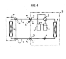
- Fig. 4 is a view showing the outdoor unit of the present embodiment used as an outdoor unit for a refrigeration unit and installed and set.
- the outdoor unit 50 has the same circuit configuration as that of the outdoor units shown in Fig. 1 and 2 ; namely, the compressor 1, the four way valve 2, the outdoor heat exchanger 3, the decompressor 4, the liquid reservoir 5, the gas pipe connection valve 6, and the liquid pipe connection valve 7 are connected together by pipes, to thus be configured and housed in the outdoor unit 50 as a refrigerant circuit component part of the outdoor unit.
- Fig. 4 shows that the outdoor unit 50 and a freezer 61 for use in a refrigeration unit are connected together by means of the gas extension pipe 10 and the liquid extension pipe 11 and installed and set as a refrigeration unit.
- freezer 61 Other than a freezer, a refrigerator, a showcase, an automatic vending machine, and the like, are equivalent to the freezer 61. All of them are products having a refrigerant circuit of the same configuration.
- a heat exchanger 15 of the freezer, a gas pipe connecting port 16, and a liquid pipe connecting port 17 are connected to the freezer 61 by means of pipes, to thus configure a refrigerant circuit component part of the freezer 61 and are housed in the freezer 61.
- the refrigerant circuit component part of the freezer 61 is connected to the refrigerant circuit component part of the outdoor unit 50 by way of the gas extension pipe 10 and the liquid extension pipe 11, thereby making up a refrigerant circuit by which the combustible low GWP HC refrigerant or the slightly combustible low GWP HFC refrigerant circulates through the freezer 61 and the outdoor unit 50.
- the gas pipe connection valve 6 and the liquid pipe connection valve 7 have the same structure and operate in the same manner as their counterparts shown in Fig. 3 .
- the refrigerant sucked from the liquid reservoir 5 and compressed by the compressor 1 flows into the outdoor heat exchanger 3 by way of the four way valve 2.
- the outdoor heat exchanger 3 exchanges heat between refrigerant flowed into the outdoor heat exchanger 3 and outdoor air of the outdoor unit 50 and condenses the refrigerant, and the thus-condensed refrigerant flows into the decompressor 4.
- the decompressor 4 decompresses the inflow refrigerant, whereupon the temperature of the refrigerant drops.
- the refrigerant subjected to a temperature drop as a result of having undergone decompression performed by the decompressor 4 flows into the heat exchanger 15 of the freezer 61 by way of the liquid pipe connection valve 7 of the outdoor unit, the liquid extension pipe 11, and the liquid pipe connecting port 17 of the freezer 61.
- the refrigerant evaporated as a result of having exchanged heat with air in the freezer 61 flows into the liquid reservoir 5 by way of the gas pipe connecting port 16 of the freezing chamber 61, the gas extension pipe 10, the gas pipe connection valve 6 of the outdoor unit, and the four way valve 2.
- the air in the freezer 61 undergoes heat exchange by circulation of the refrigerant so that goods to be stored, such as food products, in the freezer 61 can be frozen.
- the refrigerator is identical with the freezer 61 in terms of configuration and system for circulating a refrigerant.
- the freezer 61 is a freezer that freezes food products or a refrigerator that keeps the food products cold
- the flow route of the refrigerant will not be required to be switched.
- the four way valve 2 can be omitted.
- goods to be stored such as food products, in the show case or the automatic vending machine are kept warm.
- the flow route of the refrigerant is switched by the four way valve 2, thereby letting the heat exchanger 15 condense the refrigerant and the outdoor heat exchanger 3 evaporate the refrigerant.
- Circulation of the refrigerant in the refrigerant circuit is the same as that performed during heating operation. That is, the heat exchanger 15 heats air in the showcase or the automatic vending machine, whereby the goods in the showcase or the automatic vending machine are kept warm.
- Fig. 5 is a refrigerant circuit of another outdoor unit of an air-conditioning unit of the first exemplary embodiment, which supplies hot water.
- the compressor 1, the four way valve 2, the outdoor heat exchanger 3, the decompressor 4, the liquid reservoir 5, a refrigerant sealing valve 8, and a load-side heat exchanger 20 are connected to each other pipes, whereby a refrigerant circuit is configured and housed in an outdoor unit 51 in such a way that a refrigerant circulates through the outdoor unit.
- a refrigerant circuit through which the combustible low GWP refrigerant or a slightly combustible low GWP refrigerant circulates is built in the outdoor unit 51.
- the outdoor unit 50 has the gas pipe connection valve 6 and the liquid pipe connection valve 7, and a refrigerant sealing connecting port is provided on the gas pipe connection valve 6.
- the outdoor unit 51 is not equipped with the gas pipe connection valve 6 and the liquid pipe connection valve 7. Instead, the outdoor unit 51 additionally has the refrigerant sealing valve 8 for use in sealing a refrigerant.
- the load-side heat exchanger 20 is a heat exchanger that has pipe connecting ports 21 and 22 and that exchanges heat between the refrigerant and an antifreeze liquid, such as water, alcohol, and brine.
- pieces of apparatus which are unillustrated such as a supply source that is supplied with external water and a tank that supplies hot water generated by heating the water, are installed, and the pieces of apparatus are connected together by pipes.
- the hot water generated by the load-side heat exchanger 20 is stored in the tank and used as a hot water supply, or the hot water is caused to circulate through the tank or a unit that air-conditions an indoor space, to thus be used for cooling/heating operation.
- the hot water is used as a hot water supply, the essential requirement is to generate hot water, and switching of the four way valve 2 is not necessary. Therefore, the four way valve 2 can be omitted. Even when the indoor space is air-conditioned, if the air-conditioning unit is a cooling-only unit, the four way valve 2 will not be required to be switched and hence can be omitted.
- the load-side heat exchanger 20 is configured such that water flowed from the pipe connecting port 21 exchanges heat with the refrigerant, thereby generating hot water, and then exits from a pipe connecting port 22.
- the pipe connecting port 22 is equipped with an unillustrated tank, and the tank is used for using generated hot water for a hot water supply or heating operation.
- the thus-generated hot water may be circulated, that is, passing through an air-conditioning unit that air-conditions an indoor space and returning to the connecting port 21, as a secondary refrigerant.
- the refrigerant flowed into the load-side heat exchanger 20 exchanges heat with water, undergoes condensation, and then flows into the decompressor 4.
- the refrigerant subjected to temperature drop as a result of having been decompressed by the decompressor 4 is evaporated by the outdoor heat exchanger 3 and returns to the liquid reservoir 5 by way of the four way valve 2.
- the load-side heat exchanger 20 exchanges heat between the refrigerant and water, thereby generating hot water and providing a hot water supply or heating an indoor space.
- the outdoor unit performs cooling operation as an air-conditioning unit
- the four way valve 2 is switched, and the load-side heat exchanger 20 generates cold water, and the cold water is supplied as a secondary refrigerant to the indoor air-conditioning unit, whereby cooling operation is performed.
- the four way valve 2 is not switched and hence, is omitted.
- the indoor air-conditioning unit is solely for cooling purpose, switching of the four way valve 2 is not performed and hence, is omitted.
- a refrigeration unit can also be configured by utilization of the configuration of the outdoor unit shown in Fig. 5 .
- an antifreeze liquid such as alcohol and brine, is used as a secondary refrigerant for the load-side heat exchanger 20.
- Pipes are connected to a freezer located outside the outdoor unit, or the like, by way of the connecting ports 21 and 22, such that the antifreeze liquid circulates.
- Circulation of the refrigerant in the refrigerant circuit is the same as that performed during cooling operation.
- the antifreeze liquid cooled by the refrigerant in the load-side heat exchanger 20 is delivered as the secondary refrigerant to the freezer to cool air in the freezer and again returns to the load-side heat exchanger 20.
- Goods to be stored, such as food products, in the freezer are cooled.
- the freezer is a refrigerator that keeps goods to be stored, such as food products, cold
- the refrigerator is identical with the freezer in terms of configuration and system for circulating the refrigerant.
- the freezer connected to the load-side heat exchanger 20 is a show case or an automatic vending machine
- goods to be stored such as food products
- the flow route of the refrigerant is switched by the four way valve 2, thereby letting the load-side heat exchanger 20 heat the secondary refrigerant.
- Circulation of the refrigerant in the refrigerant circuit is the same as that performed for heating; namely, the secondary refrigerant heated by the refrigerant in the load-side heat exchanger 20 is delivered to the showcase or the automatic vending machine, thereby heating air in the showcase or the automatic vending machine and again returns to the load-side heat exchanger 20.
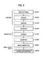
- Fig. 6 shows general procedures from manufacturing an air-conditioning unit or a refrigeration unit to performing air-conditioning or refrigerating operation.
- STEP 1 is a manufacturing step for manufacturing an air-conditioning unit or a refrigeration unit in a factory
- STEP 2 is a packing step of packing the manufactured air-conditioning unit or refrigeration unit
- STEP 3 is a shipping step of shipping the air-conditioning unit or the refrigeration unit from the factory
- STEP 4 is a conveying step of conveying the air-conditioning unit or the refrigeration unit from the factory to a warehouse
- STEP 5 is a storing step of storing the air-conditioning unit or the refrigeration unit in the warehouse
- STEP 6 is a conveying step of conveying the air-conditioning unit or the refrigeration unit from the warehouse to a place where the user is to use the air-conditioning unit or the refrigeration unit
- STEP 7 is an installation/setup step of installing or setting the air-conditioning unit or the refrigeration unit at the place where the user is to use the air-conditioning unit or
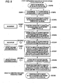
- Fig. 7 shows steps employed before and after test working and inspection in the step of manufacturing an outdoor unit.
- the step of manufacturing an outdoor unit corresponds to STEP 1 shown in Fig. 6 .
- STEP 11 to STEP 16 designate preparation steps preceding a test for sealing a test refrigerant in the outdoor unit.
- STEP 17 designates a test working/inspection step, and
- STEP 18 to STEP 26 designate post-processing steps of recovering the refrigerant, or the like.
- a refrigerant A described in connection with STEP 15 to STEP 20 designates a combustible or a slightly combustible refrigerant
- a refrigerant B described in connection with STEP 25 and STEP 26 designates an incombustible refrigerant.
- STEP 10 designates a final step in which the compressor 1, the four way valve 2, the outdoor heat exchanger 3, the decompressor 4, the liquid reservoir 5, the gas pipe connection valve 6, and the liquid pipe connection valve 7 are connected to the outdoor unit 50 by way of pipes, thereby assembling a refrigerant circuit component part of the outdoor unit 50.
- STEP 11 designates a step of connecting test load means to the gas pipe connection valve 6 and the liquid pipe connection valve 7 and opening the switching valve 6d of the gas pipe connection valve 6 and the switching valve 7d of the liquid pipe connection valve 7.
- the refrigerant circuit component part of the test load means and the refrigerant circuit component part of the outdoor unit 50 come into mutual communication as a result of opening of the switching valves 6d and 7d, whereby a refrigerant circuit through which the refrigerant circulates is made.
- the "test load means" is a dummy indoor unit intended for efficiently using an narrow production space in the factory and substitutes the indoor unit 60 shown in Fig. 2 in the manufacturing step.
- the test load means releases or absorbs heat of a refrigerant circulating between the test load means and the outdoor unit 50 as does the indoor unit 60, thereby consuming the heat.
- the vacuum pump is connected to an unillustrated; custom-designed vacuum pump connecting port provided in the outdoor unit 50.
- STEP 13 the interior of the refrigerant circuit is decompressed up to predetermined pressure at which a predetermined amount of refrigerant required to perform test working can be sealed in the refrigerant circuit made in STEP 11. After decompression, the vacuum pump is disconnected in STEP 14.
- an airtight container enclosing the refrigerant A that is to be used and that is combustible or slightly combustible is connected to the unillustrated, custom-designed connecting port provided in the outdoor unit 50, thereby sealing the predetermined amount of refrigerant required to perform test working into the outdoor unit.
- the airtight container is removed in STEP 16.
- the four way valve 2 is switched to perform test working and an inspection as to whether or not the outdoor unit can perform cooling and heating operation.
- a refrigerant recover unit and the airtight container for recovering the refrigerant A are connected in STEP 18 to an unillustrated, custom-designed connecting port provided in the refrigerant circuit.
- the refrigerant A in the refrigerant circuit namely, the combustible or slightly combustible refrigerant is recovered by means of the recovery airtight container in STEP 19.
- the refrigerant recover unit and the recovery airtight container are disconnected in STEP 20.
- the switching valve 6d of the gas pipe connection valve 6 and the switching valve 7d of the liquid pipe connection valve 7 of the outdoor unit 50 are closed, and the test load means is disconnected from the outdoor unit 50.
- the vacuum pump is again connected to the unillustrated, custom-designed connecting port provided in the outdoor unit 50.
- the interior of the refrigerant circuit is decompressed to predetermined pressure.
- the vacuum pump is disconnected in STEP 24.
- the interior of the refrigerant circuit may become nearly close to a vacuum at a point in time when the refrigerant was recovered by a refrigerant recovery unit in STEP 18 to STEP 20. In that case, processing pertaining to STEP 22 to STEP 24 may not be performed.
- the airtight container containing the refrigerant B that is an incombustible refrigerant is connected to an unillustrated, custom-designed connecting port provided in the outdoor unit 50, and the refrigerant B is sealed in the outdoor unit. After completion of sealing operation, the airtight container is disconnected in STEP 26.
- the unillustrated connecting port for connection with the vacuum pump and the unillustrated connecting port for sealing a refrigerant, which were used in STEP 11 to STEP 26, are not necessary in subsequent steps and may therefore be eliminated.
- processing proceeds to subsequent STEP 27 that is a final assembly step of attaching remaining components to the outdoor unit.
- subsequent STEP 27 is a final assembly step of attaching remaining components to the outdoor unit.
- Steps for manufacturing the outdoor unit 50 have been described thus far. Steps for manufacturing the outdoor unit 51 used for providing a hot water supply will be described hereinafter. The steps shown in Fig. 6 also apply to the outdoor unit 51. However, steps preceding and subsequent to test working and inspection in STEP 1 are as illustrated in Fig. 8 . The preparation step before the test, the test working/inspection step, and the post-processing step are the same as their counterparts shown in Fig. 7 . STEP 30 also designates a final step of assembling an outdoor unit as in Fig. 7 . In STEP 11 shown in Fig. 7 , the test load means is connected to the gas pipe connection valve 6 and the liquid pipe connection valve 7 of the outdoor unit 50.
- the outdoor unit 51 is not equipped with the gas pipe connection valve 6 and the liquid pipe connection valve 7.
- the outdoor unit 51 is configured such that a refrigerant can circulate through a refrigerant circuit provided in the outdoor unit 51 without connection with the test load means. That is, test load means equivalent to the indoor unit 60 does not need to be connected. Instead, in STEP 31 shown in Fig. 8 , another test load means is connected to the connecting ports 21 and 22 shown in Fig. 5 , and by causing an antifreeze liquid, such as water, alcohol, or brine, to circulate through the load-side heat exchanger 20, heat exchange operation is performed.
- STEP 32 to STEP 46 are the same as their counterpart steps for the outdoor unit 50.
- STEP 32 a vacuum pump is connected to the outdoor unit 51, and an interior of the refrigerant circuit of the outdoor unit 51 is decompressed to predetermined pressure in STEP 33. After completion of decompression operation, the vacuum pump is disconnected in STEP 34.
- STEP 35 an airtight container containing the refrigerant A that is a combustible or slightly combustible refrigerant is connected, thereby sealing the refrigerant A into the outdoor unit. After completion of sealing operation, the airtight container is disconnected in STEP 36.
- STEP 37 test working/inspection is performed as to whether or not the outdoor unit can properly work.
- the refrigerant recover unit and the airtight container for recovering the refrigerant A are connected together, and the refrigerant A is recovered in STEP 39.
- the refrigerant recovery unit and the recovery airtight container are disconnected from each other in STEP 40.
- the water or the antifreeze liquid is drained from the test load means and the load-side heat exchanger 20, and the test load means is disconnected from the outdoor unit 57.
- the vacuum pump is again connected, and the interior of the refrigerant circuit is decompressed to the predetermined pressure in STEP 43. After completion of decompression operation, the vacuum pump is disconnected in STEP 44.
- processing pertaining to STEP 42 to STEP 44 may not be performed.
- the airtight container containing the refrigerant B that is an incombustible refrigerant is connected in STEP 45, and the refrigerant B is sealed in the outdoor unit. After completion of sealing operation, the airtight container is disconnected in STEP 46.
- the unillustrated connecting port for connection with the vacuum pump and the unillustrated connecting port for sealing a refrigerant, which were used in STEP 31 to STEP 46 are not necessary in subsequent steps and therefore, may be eliminated.
- processing proceeds to subsequent STEP 47 that is a final assembly step of attaching remaining components to the outdoor unit 50.
- low GWP refrigerants exhibiting a GWP of less than 150 such as the HC refrigerants like propane, butane, and isobutene, and the HFC refrigerants like HFO1234yf are used as the combustible refrigerant or the slightly combustible refrigerant sealed in the refrigerant circuit.
- the refrigerant may catch fire. Accordingly, a contrivance is made to minimize a time and a number of steps during which the combustible refrigerant or the slightly combustible refrigerant is used in the manufacturing steps, and a place where the outdoor unit is to be used is well ventilated, to thus prevent accumulation of the refrigerant.
- an HFC refrigerant such as R410A and R407C, or a natural refrigerant like CO 2 that is capable of phase change, to thus be able to use latent heat, under pressure conditions of a refrigerant that circulates through a refrigerant circuit during air-conditioning operation of an air-conditioning unit or refrigerating operation of a refrigeration unit.
- An inert gas such as nitrogen, helium, and argon, is also available as an incombustible material.
- the inert gas is not capable of a phase change, to thus be able to use latent heat, under pressure conditions of a refrigerant that circulates through a refrigerant circuit during air-conditioning operation of the air-conditioning unit or refrigerating operation of the refrigeration unit. Therefore, the inert gas does not act as a refrigerant in the refrigerant circuit and is not suitable as an incombustible refrigerant of the present invention and hence not used.
- the amount of incombustible refrigerant sealed in the refrigerant circuit component parts of the outdoor units 50 and 51 is determined so that a pressure of the incombustible refrigerant is an atmospheric pressure or more. Accordingly, even if the refrigerant circuit is accidentally brought into mutual communication with the atmosphere in any of the shipping step, the storing step, the conveying step, and the setup step, entry of the atmosphere into the refrigerant circuit component parts of the outdoor units 50 and 51 is prevented.
- guidelines such as an intensity of the refrigerant circuit, are described in JISB8020, or the like, so as to prevent pipes of the refrigerant circuit from being damaged by a refrigerant gas sealed in the refrigerant circuit.
- design pressure A pressure limitation achieved as a result of intensity of the refrigerant circuit being designed so as to prevent occurrence of fractures, in compliance with the guidelines, is referred to as design pressure.
- the outdoor units 50 and 51 are designed so as to use a combustible low GWP refrigerant or a slightly combustible low GWP refrigerant
- the outdoor units are equipped with a refrigerant circuit having strength of design pressure that prevents occurrence of fractures when the combustible low GWP refrigerant or the slightly combustible low GWP refrigerant is sealed in the refrigerant circuit.
- a density of the combustible low GWP refrigerant or the slightly combustible low GWP refrigerant is about 100 times or more than that of an incombustible refrigerant.
- design pressure for the combustible low GWP refrigerant or the slightly combustible low GWP refrigerant becomes lower than design pressure for the incombustible refrigerant. Therefore, even when the incombustible refrigerant is sealed up to the design pressure for the combustible low GWP refrigerant or the slightly combustible low GWP refrigerant, the amount of sealed refrigerant becomes small, and hence a break or deformation, which would otherwise arise when the internal pressure of the refrigerant circuit component parts of the outdoor units 50 and 51 become too high, does not occur.
- the refrigerant sealed in the refrigerant circuit component part of the outdoor unit 50 and the refrigerant circuit component part of the outdoor unit 51 is an incombustible refrigerant. Therefore, even if the refrigerant leaks near flames as a result of the outdoor unit having toppled down, the refrigerant may not catch fire. Further, the refrigerant circuit component part of the load unit, such as the indoor unit 60 and the freezer 61, does not have any sealing valve, such as the switching valve.
- the indoor unit 60 and the freezer 61 are shipped while their refrigerant circuit component parts remain in mutual communication with the atmosphere, they are originally free from a risk of fire. Further, a load unit, such as a hot water supply unit, connected to the outdoor unit 51 is not equipped with a refrigerant circuit. Accordingly, the load unit does not raise a fire problem, either.
- a refrigerant cylinder that is filled with a combustible or slightly combustible refrigerant and that is to be sealed into an air-conditioning unit or a refrigeration unit on site is also conveyed along with the air-conditioning unit or the refrigeration unit.
- the air-conditioning unit or the refrigeration unit and the refrigerant cylinder filled with a combustible or slightly combustible refrigerant do not always need to be conveyed in the same transport means.
- the air-conditioning unit or the refrigeration unit can first be carried to a place where the air-conditioning unit or the refrigeration unit is to be set, and the refrigerant cylinder can later be carried.
- the refrigerant cylinder may be carried at the same time as the air-conditioning unit or the refrigeration unit by different transport means.
- the air-conditioning unit or the refrigeration unit and the refrigerant cylinder in different transport means, even if a refrigerant leaks near flames as a result of the indoor unit 60 or the outdoor unit 50, which configure an air-conditioning unit or a refrigeration unit, having toppled down, there is no danger of catching fire.
- the air-conditioning unit or the refrigeration unit and the refrigerant cylinder are conveyed by different transport means, whereby installation work can be enhanced by first conveying the air-conditioning unit or the refrigeration unit and subsequently conveying the refrigerant cylinder after completion of installation of the air-conditioning unit or the refrigeration unit. Meanwhile, conveying the air-conditioning unit or the refrigeration unit and the refrigerant cylinder in the same transport means does not raise any problem. All you need to do at that time is to take sufficient safety measures against toppling of the refrigerant cylinder.
- the air-conditioning unit or the refrigeration unit and the refrigerant cylinder filled with the combustible or slightly combustible refrigerant can be stored in different warehouses as in the conveying step. Even if a refrigerant leaks near flames as a result of the indoor unit 60 and the outdoor unit 50, which configure the air-conditioning unit or the refrigeration unit, having toppled down, the refrigerant cannot catch fire, because the air-conditioning unit or the refrigeration unit and the refrigerant cylinder are separately stored.
- the mark or sticker providing a notice to the people around the outdoor unit may be provided at any place, as long as the mark or sticker is visible during storage and conveyance.
- the mark or sticker can also be affixed on an exterior wall of the outdoor unit.
- Fig. 9 shows a step of installing the outdoor unit 50 and the indoor unit 60 at a predetermined place where the user is to use both the outdoor unit 50 and the indoor unit 60.
- STEP 50 shows start of installation and setup operation.
- the outdoor unit 50 and the indoor unit 60 are placed at a predetermined place where the user is to use them.
- STEP 53 after completion of installation, the liquid extension pipe 11 is connected to the liquid pipe connection valve 7 of the outdoor unit 50 and the liquid pipe connecting port 13 of the indoor unit 60, and the gas extension pipe 10 is connected to the gas pipe connection valve 6 of the outdoor unit 50 and the gas pipe connecting port 12 of the indoor unit 60.
- the switching valves 6d, 6e, and 7d of the gas pipe connection valve 6 and the liquid pipe connection valve 7, which are in a factory shipped state, are in a fully-closed state, and thus, the refrigerant circuit component part of the indoor unit 60 and the refrigerant circuit component part of the outdoor unit 50 are not yet in mutual communication with each other.
- electric wiring for establishing communication between the indoor unit 60 and the outdoor unit 50 and electric wiring for supplying electric power to activate a compressor are assumed to have already been completed before STEP 53.
- the vacuum pump is connected to the connecting port 6c of the gas pipe connection valve 6.
- the switching valve 6e of the gas pipe connection valve 6 is opened, thereby decompressing the refrigerant circuit component part of the indoor unit 60 and the interior of the extension pipes 10 and 11 until a pressure comes to 100 Pa or less. After completion of decompression, the switching valve 6e of the gas pipe connection valve 6 is closed in STEP 56, and the vacuum pump is disconnected. In STEP 57, the refrigerant cylinder filled with the refrigerant A, which is a combustible or slightly combustible refrigerant, is connected to the connecting port 6c of the gas pipe connection valve 6.
- the switching valve 6e of the gas pipe connection valve 6 is opened, thereby sealing the refrigerant A into the refrigerant circuit component part of the indoor unit 60 and the extension pipes 10 and 11. After completion of sealing operation, the switching valve 6e is closed in STEP 58, thereby disconnecting the refrigerant cylinder. In STEP 59, the switching valve 6d of the gas pipe connection valve 6 and the switching valve 7d of the liquid pipe connection valve 7 are opened. The refrigerant circuit component part of the indoor unit 60 and the refrigerant circuit component part of the outdoor unit 50 are brought into mutual communication by opening the switching valves 6d and 7d, whereby the sealed refrigerant A goes to the refrigerant circuit component part of the outdoor unit, too. STEP 60 designates completion of installation or setup operation.
- the switching valve 6d of the gas pipe connection valve 6 and the switching valve 7d of the liquid pipe connection valve 7 are opened, thereby bringing the refrigerant circuit component part of the indoor unit 60 and the refrigerant circuit component part of the outdoor unit 50 into mutual communication with each other; where the compressor 1 is subjected to operation (e.g., cooling operation, or the like), to thus seal a required amount of combustible or slightly combustible refrigerant in the refrigerant circuit; and where the switching valve 6e of the gas pipe connection valve 6 is finally closed, to thus disconnect the cylinder.
- operation e.g., cooling operation, or the like
- the combustible or slightly combustible refrigerant can additionally be sealed without recovering the incombustible refrigerant from the refrigerant circuit component part of the outdoor unit 50.
- the refrigeration unit including the freezer 61 and the outdoor unit 50 can be installed and set through substantially the same steps.
- the switching valves 6d and 7d can be opened before opening of the switching valve 6e, thereby bringing the refrigerant circuit component part of the indoor unit 60 and the refrigerant circuit component part of the outdoor unit 50 into mutual communication and subsequently, the switching valve 6e can be opened to seal the refrigerant A into the refrigerant circuit component part.
- the switching valve 6e for opening and closing the refrigerant sealing connecting port 6c and the connecting port 6c are provided in the gas pipe connection valve 6.
- the connecting port 6c and the switching valve 6e may be provided to the refrigerant pipes of the indoor unit 60 or the extension pipes 10 and 11.
- the setup and installation step remains unchanged, and the vacuum pump is connected to the connecting port 6c in STEP 54 to STEP 58, and the switching valve 6e is opened, thereby producing a vacuum in the refrigerant circuit component part of the indoor unit 60. After the vacuum has been produced, the switching valve 6e is temporarily closed.
- Steps subsequent to STEP 59 are the same as those described previously.
- the refrigerant sealing connecting port 6c and the switching valve 6e can be provided at any position between the pipe connecting port 6a of the gas pipe connection valve 6 and the four way valve 2 shown in Fig. 1 .
- another switching valve capable of performing opening and closing operations must be attached to any position between the four way valve 2 and the place where the refrigerant sealing connecting port 6c is attached.
- the switching valve 6d is opened while the switching valve 7d and the switching valve provided between the connecting port 6c and the four way valve 2 remain closed. The vacuum pump is thereby connected to a circuit made up of the indoor unit 60 and the extension pipes 10 and 11.
- the refrigerant sealing connecting port 6c and the switching valve 6e can be provided at any position between the pipe connecting port 7a of the liquid pipe connection valve 7 and the decompressor 4 shown in Fig. 1 .
- another switching valve capable of performing opening and closing operations must be attached to any place between the decompressor 4 and the place where the refrigerant sealing connecting port 6c is attached.
- the switching valve 7d is opened while the switching valve 6d and the switching valve provided between the connecting port 6c and the decompressor 4 remain closed. The vacuum pump is thereby connected to a circuit made up of the indoor unit 60 and the extension pipes 10 and 11.
- STEP 59 the switching valve 6d and the switching valve provided between the connecting port 6c and the decompressor 4 are opened, thereby bringing the refrigerant circuit component part of the indoor unit 60 in communication with the refrigerant circuit component part of the outdoor unit 50.
- Fig. 10 shows a step of setting the outdoor unit 51 and a load unit at a predetermined place where the user is to use the outdoor unit and the load unit.
- STEP 70 shows start of installation and setup operation.
- the outdoor unit 51 and the load unit are set at a predetermined place where the user is to use the outdoor unit and the load unit.
- the load unit are a hot water storage unit, a freezer, a refrigerator, and the like, connected to the outdoor unit 51 by way of the connecting ports 21 and 22, or the load unit may be an air-conditioning facility where the pipes thereof are embedded in a wall or floor of a room when in use.
- STEP 73 the outdoor unit 51 and the load unit are connected together, thereby enabling circulation of water or an antifreeze liquid. Electric wiring between the outdoor unit 51 and the load unit and electric wiring for supplying electric power are assumed to have already been completed before STEP 73.
- STEP 74 a refrigerant cylinder filled with the combustible or slightly combustible refrigerant A is connected to a connecting port of the refrigerant sealing valve 8. The refrigerant A is sealed in the refrigerant circuit of the outdoor unit 51 by opening a switching valve of the refrigerant sealing valve 8.
- the combustible or slightly combustible low GWP refrigerant undergoes a phase change from liquid to gas in the heat exchanger, or the like, that is an evaporator, or a phase change from gas to liquid in the heat exchanger, or the like, that is a condenser.
- the heat exchanger thereby performs heat exchange operation, thereby air-conditioning a room space or freezing food products.
- the incombustible refrigerant is selected from HFC refrigerants, such as R410A and R407C, or natural refrigerants, such as CO 2
- the refrigerant causes a phase change from liquid to gas in the heat exchanger, or the like, that is an evaporator, or a phase change from gas to liquid in the heat exchanger, or the like, that is a condenser, when circulating through the refrigerant circuit under internal pressure conditions for the refrigerant circuit achieved during air-conditioning operation or refrigerating operation.
- the incombustible refrigerant when the combustible or slightly combustible low GWP refrigerant performs heat exchange by circulating through the refrigerant circuit, the incombustible refrigerant does not hinder heat exchange action of the combustible or slightly combustible low GWP refrigerant. Moreover, since the incombustible refrigerant itself performs heat exchange by circulation, heat exchange capability is not hindered.
- the amount of incombustible refrigerant sealed is determined so that a pressure of the incombustible refrigerant is equal to or higher than the atmospheric pressure and equal to or lower than the design pressure of the refrigerant circuit of the outdoor unit using a combustible or slightly combustible low GWP refrigerant, the incombustible refrigerant is sealed in small amount that is about one-hundredth of an amount of combustible or slightly combustible low GWP refrigerant, which will be additionally sealed later, or less. Since the amount of incombustible refrigerant that performs heat exchange by circulating through the refrigerant circuit is relatively small, heat exchange capability of the combustible or slightly combustible low GWP refrigerant is sufficiently exhibited.
- both of the outdoor units 50 and 51 are large scale refrigerant circuits, an amount of refrigerant more than necessary is sealed in the refrigerant circuits during air-conditioning or refrigerating operation, in order to sufficiently exhibit refrigerating capability by accommodating to a difference in setup conditions arising on site. Excessive refrigerant is temporarily recovered and stored in the liquid reservoir 5.
- the amount of incombustible refrigerant sealed is an amount of refrigerant fulfilling the design pressure of the refrigerant circuit of the outdoor unit using a combustible or slightly combustible low GWP refrigerant, the amount of incombustible refrigerant sealed is still extremely smaller than the amount of combustible or slightly combustible low GWP refrigerant sealed on site. Further, in the air-conditioning unit or the refrigeration unit of the present invention, the incombustible refrigerant is sealed only in the refrigerant circuit component part of the outdoor unit 50.
- the relative amount of incombustible refrigerant becomes even smaller. Therefore, even when the incombustible refrigerant circulates through the refrigerant circuit, the incombustible refrigerant does not hinder the heat exchange capability exhibited by the combustible or slightly combustible refrigerant.
- the air-conditioning unit or the refrigeration unit does not induce large deterioration of performance. Rather, predetermined capability achieved when the combustible or slightly combustible low GWP refrigerant is sealed can be exhibited.
- a refrigerant sealed and used during air-conditioning or refrigerating operation is a combustible HC refrigerant
- a small amount of HC refrigerant may be previously mixed in the incombustible refrigerant sealed in an outdoor unit shipped from the factory.
- the HC refrigerant exhibits high compatibility with a mineral oil that is a lubricant for the compressor, whilst the incombustible HFC refrigerant previously sealed in the outdoor unit exhibits low compatibility with the mineral oil.
- the mineral oil circulates through the refrigerant circuit along with the HC refrigerant and returns to the compressor as long as the HC refrigerant exhibiting high compatibility with the mineral oil is sealed in amounts of about 10 to 20 percents of the amount of mineral oil along with the incombustible refrigerant. Consequently, depletion of oil in the compressor can be avoided, thereby preventing occurrence of a failure in compressor.
- the HC refrigerant employed at this time can be an HC refrigerant sealed during air-conditioning or refrigerating operation or another HC refrigerant, such as R422D and R600a, which does not hinder circulation of an HC refrigerant additionally sealed on site.
- the amount of HC refrigerant sealed concurrently with the incombustible refrigerant in order to ensure compatibility differs according to a length of the refrigerant circuit or an amount of refrigerant or mineral oil sealed. For these reasons, the amount of HC refrigerant sealed is not necessarily about 10 to 20 percents of the amount of mineral oil. Any amount of HC refrigerant is acceptable, so long as the HC refrigerant circulates through the refrigerant circuit and returns to the compressor.
- R422D and R600a are combustible refrigerants.
- a sufficient amount of combustible refrigerant is as small as about 10 to 20 percents of the amount of mineral oil. Therefore, even if a refrigerant leaks as a result of the outdoor unit having fallen or toppled down in the storage or conveying step, a possibility of occurrence of firing due to leakage of the refrigerant is low.
- the amount of HC refrigerant is about 10 to 20 percents of the amount of mineral oil as in the case with R422D or R600a. Therefore, even if a refrigerant leaks as a result of the outdoor unit having fallen or toppled down in the storage or conveying step, a possibility of occurrence of firing due to leakage of the refrigerant is low.
- the outdoor unit when the outdoor unit that is shipped from the factory after an incombustible refrigerant has been sealed in a refrigerant circuit thereof is set at a place where the user is to use the outdoor unit, the outdoor unit can be used by additionally sealing a required amount of combustible refrigerant or slightly combustible refrigerant into a refrigerant circuit without recovery of the incombustible refrigerant sealed before shipment from the refrigerant circuit, that is, while the incombustible refrigerant is sealed in the refrigerant circuit.
- an air-conditioning unit or a refrigeration unit using a combustible refrigerant or a slightly combustible refrigerant, wherein safety in steps of shipping, storing, and conveying the air-conditioning unit or the refrigeration unit can be assured and work load imposed during setup operation on site can be lessened.
- the possibility of the refrigerant catching fire is low. Further, the incombustible refrigerant does not need to be recovered during setup operation. Therefore, the possibility of the incombustible refrigerant being released into the atmosphere is low.
- an HC refrigerant such as propane, butane, and isobutene
- an HFC refrigerant such as HFO1234yf which have a low GWP refrigerant exhibiting a GWP of less than 150
- a combustible or slightly combustible refrigerant sealed in an air-conditioning unit or a refrigeration unit at the timing of inspection in manufacturing steps and after setup on site, so to be useable.
- ozone layer will not be destroyed and the refrigerant exhibits a small GWP, and therefore, is friendly to the global environment.
- an HFC refrigerant such as R410A and R407C, or a natural refrigerant, such as CO 2
- an incombustible refrigerant changes its phase from liquid to gas or gas to liquid under pressure conditions for the refrigerant required during air-conditioning or refrigerating operation, heat exchange of the additionally sealed HC refrigerant or HFC refrigerant is not hindered. Further, even if a refrigerant leaks as a result of the outdoor unit having fallen or toppled down in the storage or conveying step, the possibility of occurrence of firing due to leakage of the refrigerant is low.
- the refrigerant circuit of the present embodiment of this invention is a large scale refrigerant circuit having a liquid reservoir for storing excessive refrigerant.
- an additionally sealed combustible or slightly combustible refrigerant is sealed in an amount more than necessary.
- the amount of incombustible refrigerant sealed before shipment from the factory is smaller than the amount of additionally sealed combustible or slightly combustible refrigerant.
- the amount of incombustible refrigerant sealed before shipment from the factory is smaller than the amount of combustible or slightly combustible low GWP refrigerant additionally sealed during installation and setup operation. Therefore, even when a small amount of incombustible refrigerant exhibiting a high GWP is mixed with the combustible or slightly combustible low GWP refrigerant, the GWP exhibited by the entire refrigerant can be maintained less than 150. Accordingly, there can be provided an air-conditioning unit or a refrigeration unit in which a low GWP refrigerant fulfilling a target GWP of less than 150 is sealed.
- a small amount of HC refrigerant is previously mixed in an incombustible refrigerant. Therefore, even if the compressor is started while sealing of the HC refrigerant is forgotten during work for setting an outdoor unit having a refrigerant circuit component part in which an HFC refrigerant has previously been sealed, an HC refrigerant exhibiting high compatibility with a mineral oil circulates through the refrigerant circuit along with the mineral oil and returns to the compressor. Thus, depletion of oil in the compressor can be avoided, and a failure does not take place in the compressor.
- the HC refrigerant employed at this time can be an HC refrigerant sealed during air-conditioning or refrigerating operation or another HC refrigerant, such as R422D and R600a, which does not hinder circulation of the HC refrigerant additionally sealed on site.
- R422D or R600a is a combustible refrigerant
- the amount of R422D or R600a included in the incombustible refrigerant is small.
- means for notifying people around an outdoor unit that an incombustible refrigerant is sealed in the outdoor unit during storage, shipment, and conveying operations and that a combustible or slightly combustible refrigerant is sealed in the outdoor unit when the outdoor unit is set is provided on a surface of a packing material of the outdoor unit in steps of manufacturing outdoor units for refrigeration units or air-conditioning units.
- the combustible or slightly combustible refrigerant sealed in the outdoor unit is stored, shipped, and conveyed in a space separated from the outdoor unit in steps of shipping, storing, and conveying the outdoor unit of the air-conditioning unit or the refrigeration unit. Therefore, even if a combustible refrigerant leaks as a result of the outdoor unit having fallen or topped down in the storage, shipment, or conveying step, there is little possibility of occurrence of firing due to leakage of the refrigerant.
Landscapes
- Engineering & Computer Science (AREA)
- Mechanical Engineering (AREA)
- Physics & Mathematics (AREA)
- Thermal Sciences (AREA)
- General Engineering & Computer Science (AREA)
- Other Air-Conditioning Systems (AREA)
- Devices That Are Associated With Refrigeration Equipment (AREA)
Applications Claiming Priority (1)
| Application Number | Priority Date | Filing Date | Title |
|---|---|---|---|
| JP2009249002A JP2011094871A (ja) | 2009-10-29 | 2009-10-29 | 冷凍・空調装置、冷凍・空調装置の設置方法 |
Publications (3)
| Publication Number | Publication Date |
|---|---|
| EP2317253A2 true EP2317253A2 (de) | 2011-05-04 |
| EP2317253A3 EP2317253A3 (de) | 2012-08-15 |
| EP2317253B1 EP2317253B1 (de) | 2019-10-23 |
Family
ID=43466399
Family Applications (1)
| Application Number | Title | Priority Date | Filing Date |
|---|---|---|---|
| EP10009570.2A Active EP2317253B1 (de) | 2009-10-29 | 2010-09-14 | Vorrichtung mit Kühlmittel und Verfahren zur Installation der Vorrichtung mit dem Kühlmittel |
Country Status (4)
| Country | Link |
|---|---|
| US (2) | US20110219794A1 (de) |
| EP (1) | EP2317253B1 (de) |
| JP (1) | JP2011094871A (de) |
| CN (1) | CN102052810B (de) |
Cited By (3)
| Publication number | Priority date | Publication date | Assignee | Title |
|---|---|---|---|---|
| EP3067643A4 (de) * | 2013-11-08 | 2017-09-06 | Mitsubishi Electric Corporation | Kältekreislaufvorrichtung sowie herstellungsverfahren und installationsverfahren dafür |
| EP2559959A3 (de) * | 2011-08-18 | 2018-07-11 | Mitsubishi Electric Corporation | Außeneinheit und Klimaanlage |
| US12345454B2 (en) | 2020-03-04 | 2025-07-01 | Daikin Industries, Ltd. | Refrigerant cycle apparatus and method for installing refrigerant cycle apparatus |
Families Citing this family (17)
| Publication number | Priority date | Publication date | Assignee | Title |
|---|---|---|---|---|
| JPWO2013111180A1 (ja) * | 2012-01-24 | 2015-05-11 | 三菱電機株式会社 | 空気調和装置の冷媒充填方法、空気調和装置 |
| EP2808625B1 (de) | 2012-01-24 | 2020-05-20 | Mitsubishi Electric Corporation | Kältelmittelnachfüllverfahren für eine klimaanlage |
| US9593870B2 (en) | 2012-12-03 | 2017-03-14 | Whirlpool Corporation | Refrigerator with thermoelectric device for ice making |
| US9175888B2 (en) | 2012-12-03 | 2015-11-03 | Whirlpool Corporation | Low energy refrigerator heat source |
| JP5697710B2 (ja) * | 2013-04-08 | 2015-04-08 | 三菱電機株式会社 | 冷凍サイクル装置 |
| JP5731581B2 (ja) * | 2013-06-25 | 2015-06-10 | 三菱電機株式会社 | 空気調和装置 |
| US10107514B2 (en) * | 2013-08-28 | 2018-10-23 | Mitsubishi Electric Corporation | Air-conditioning apparatus including multiple expansion devices |
| DE102014104709A1 (de) * | 2014-04-02 | 2015-10-08 | Krones Ag | Behälterbehandlungsanlage mit Kälteanlage und Verfahren zur Inbetriebnahme einer Kälteanlage einer Behälterbehandlungsanlage |
| CN103954086B (zh) * | 2014-05-22 | 2017-02-22 | 珠海格力电器股份有限公司 | 一种空调器灌注制冷剂的方法 |
| WO2016013077A1 (ja) * | 2014-07-23 | 2016-01-28 | 三菱電機株式会社 | 冷凍サイクル装置 |
| CN106322804B (zh) * | 2015-06-30 | 2023-03-31 | 开利公司 | 制冷系统及其净化方法 |
| JP2017207256A (ja) * | 2016-05-20 | 2017-11-24 | 三菱重工サーマルシステムズ株式会社 | 空気調和装置及び空気調和装置の制御方法 |
| DE102017206547A1 (de) * | 2017-04-19 | 2018-10-25 | Robert Bosch Gmbh | Verfahren zum Befüllen eines Rohrleitungskreislaufs einer Wärmepumpe mit einem Kältemittel, Behälter dafür und Wärmepumpe |
| US20190122479A1 (en) * | 2017-10-23 | 2019-04-25 | Nidec Motor Corporation | Drive system for vending machine |
| JP6998780B2 (ja) * | 2018-02-02 | 2022-01-18 | 株式会社デンソー | 冷凍サイクル装置 |
| EP3859241B1 (de) * | 2018-09-28 | 2024-07-10 | Daikin Industries, Ltd. | Kühlmitteleinfüllverfahren |
| WO2023189391A1 (ja) | 2022-03-30 | 2023-10-05 | ダイキン工業株式会社 | 空調ユニットおよび梱包ユニット |
Citations (2)
| Publication number | Priority date | Publication date | Assignee | Title |
|---|---|---|---|---|
| JPH09229522A (ja) | 1996-02-19 | 1997-09-05 | Matsushita Refrig Co Ltd | 冷蔵庫 |
| JP2000046446A (ja) | 1998-05-26 | 2000-02-18 | Matsushita Electric Ind Co Ltd | 空気調和装置の保管・運送・設置方法 |
Family Cites Families (19)
| Publication number | Priority date | Publication date | Assignee | Title |
|---|---|---|---|---|
| JPH06273007A (ja) * | 1993-03-25 | 1994-09-30 | Hitachi Ltd | 空気調和機のレトロフィット作業方法 |
| JPH08271024A (ja) * | 1995-03-31 | 1996-10-18 | Toshiba Ave Corp | 空気調和機 |
| TW330977B (en) * | 1996-06-04 | 1998-05-01 | Jinkichi Aizawa | Heat exchanger, method of reusing and recovering refrigerant thereof |
| JP4520127B2 (ja) * | 1998-05-26 | 2010-08-04 | パナソニック株式会社 | 空気調和装置の室外機保管・運送・設置方法、及び冷凍装置の保管・運送・設置方法 |
| JP3327215B2 (ja) * | 1998-07-22 | 2002-09-24 | 三菱電機株式会社 | 空気調和機の冷媒充填量決定方法 |
| JP3109500B2 (ja) * | 1998-12-16 | 2000-11-13 | ダイキン工業株式会社 | 冷凍装置 |
| BR0110362A (pt) * | 2000-04-28 | 2003-03-05 | Daikin Ind Ltd | Método de operação de coletar refrigerante e óleo e dispositivo de controlar a coleta de refrigerante e óleo |
| JP2003028542A (ja) * | 2001-07-16 | 2003-01-29 | Daikin Ind Ltd | 冷凍装置 |
| US6519966B1 (en) * | 2001-09-10 | 2003-02-18 | Lendell Martin, Sr. | Air conditioning and heat pump systems |
| KR100432224B1 (ko) * | 2002-05-01 | 2004-05-20 | 삼성전자주식회사 | 공기 조화기의 냉매 누설 검출 방법 |
| JP2004198063A (ja) * | 2002-12-20 | 2004-07-15 | Sanyo Electric Co Ltd | 非共沸混合冷媒および冷凍サイクル、並びに冷凍装置 |
| JP2004324991A (ja) * | 2003-04-25 | 2004-11-18 | Hitachi Home & Life Solutions Inc | 冷蔵庫 |
| US7007493B2 (en) * | 2003-07-21 | 2006-03-07 | Delphi Technologies, Inc. | Front-end integral air-conditioning unit |
| JP2006162122A (ja) * | 2004-12-06 | 2006-06-22 | Sanden Corp | 車両用空調装置 |
| JP5407052B2 (ja) * | 2005-08-17 | 2014-02-05 | 昭和電工ガスプロダクツ株式会社 | 冷媒組成物 |
| JP5336039B2 (ja) * | 2006-07-21 | 2013-11-06 | ダイキン工業株式会社 | 二酸化炭素を冷媒として用いる冷凍装置における冷媒充填方法 |
| JP2008215672A (ja) * | 2007-03-01 | 2008-09-18 | Mac:Kk | 可燃性冷媒ガスを使用する冷凍サイクルの残留ガス回収方法及びその装置 |
| US20080216491A1 (en) * | 2007-03-08 | 2008-09-11 | Quest William J | Pressure gauges and methods of use |
| JP2009257652A (ja) * | 2008-02-29 | 2009-11-05 | Daikin Ind Ltd | 冷凍装置 |
-
2009
- 2009-10-29 JP JP2009249002A patent/JP2011094871A/ja active Pending
-
2010
- 2010-09-14 EP EP10009570.2A patent/EP2317253B1/de active Active
- 2010-09-14 US US12/881,455 patent/US20110219794A1/en not_active Abandoned
- 2010-09-15 CN CN2010102829247A patent/CN102052810B/zh not_active Expired - Fee Related
-
2015
- 2015-04-03 US US14/678,420 patent/US20150209920A1/en not_active Abandoned
Patent Citations (2)
| Publication number | Priority date | Publication date | Assignee | Title |
|---|---|---|---|---|
| JPH09229522A (ja) | 1996-02-19 | 1997-09-05 | Matsushita Refrig Co Ltd | 冷蔵庫 |
| JP2000046446A (ja) | 1998-05-26 | 2000-02-18 | Matsushita Electric Ind Co Ltd | 空気調和装置の保管・運送・設置方法 |
Cited By (4)
| Publication number | Priority date | Publication date | Assignee | Title |
|---|---|---|---|---|
| EP2559959A3 (de) * | 2011-08-18 | 2018-07-11 | Mitsubishi Electric Corporation | Außeneinheit und Klimaanlage |
| EP3067643A4 (de) * | 2013-11-08 | 2017-09-06 | Mitsubishi Electric Corporation | Kältekreislaufvorrichtung sowie herstellungsverfahren und installationsverfahren dafür |
| US10281182B2 (en) | 2013-11-08 | 2019-05-07 | Mitsubishi Electric Corporation | Refrigeration cycle apparatus, method of manufacturing the same, and method of installing the same |
| US12345454B2 (en) | 2020-03-04 | 2025-07-01 | Daikin Industries, Ltd. | Refrigerant cycle apparatus and method for installing refrigerant cycle apparatus |
Also Published As
| Publication number | Publication date |
|---|---|
| US20110219794A1 (en) | 2011-09-15 |
| HK1157856A1 (en) | 2012-07-06 |
| JP2011094871A (ja) | 2011-05-12 |
| EP2317253B1 (de) | 2019-10-23 |
| EP2317253A3 (de) | 2012-08-15 |
| CN102052810B (zh) | 2013-01-23 |
| CN102052810A (zh) | 2011-05-11 |
| US20150209920A1 (en) | 2015-07-30 |
Similar Documents
| Publication | Publication Date | Title |
|---|---|---|
| EP2317253B1 (de) | Vorrichtung mit Kühlmittel und Verfahren zur Installation der Vorrichtung mit dem Kühlmittel | |
| JP3501678B2 (ja) | 空気調和装置の保管・運送・設置方法 | |
| US11015828B2 (en) | Refrigeration system with utilization unit leak detection | |
| US11041666B2 (en) | Refrigeration apparatus | |
| CN102954614B (zh) | 室外机及空调装置 | |
| WO2018198203A1 (ja) | 二元冷凍装置 | |
| JP2018091502A (ja) | 冷凍装置 | |
| AU2014345151B2 (en) | Refrigeration cycle apparatus, method of manufacturing the same, and method of installing the same | |
| JP7005855B2 (ja) | 冷却システム及び冷却システムの改造方法 | |
| JP2011052863A (ja) | 冷却貯蔵庫及び冷却貯蔵庫の冷凍装置の冷媒漏れ検査方法 | |
| JP4520127B2 (ja) | 空気調和装置の室外機保管・運送・設置方法、及び冷凍装置の保管・運送・設置方法 | |
| JP6583288B2 (ja) | 作動媒体回収装置 | |
| JP2018009768A (ja) | 冷凍システム | |
| HK1157856B (en) | Refrigeration/air-conditioning apparatus and method of installing the refrigeration/air-conditioning apparatus | |
| JP2000274745A (ja) | 冷凍装置 | |
| JP2001201117A (ja) | ダイナミックアイスによる冷凍方法及び装置 | |
| JP2006145078A (ja) | 冷蔵庫 |
Legal Events
| Date | Code | Title | Description |
|---|---|---|---|
| PUAI | Public reference made under article 153(3) epc to a published international application that has entered the european phase |
Free format text: ORIGINAL CODE: 0009012 |
|
| AK | Designated contracting states |
Kind code of ref document: A2 Designated state(s): AL AT BE BG CH CY CZ DE DK EE ES FI FR GB GR HR HU IE IS IT LI LT LU LV MC MK MT NL NO PL PT RO SE SI SK SM TR |
|
| AX | Request for extension of the european patent |
Extension state: BA ME RS |
|
| PUAL | Search report despatched |
Free format text: ORIGINAL CODE: 0009013 |
|
| AK | Designated contracting states |
Kind code of ref document: A3 Designated state(s): AL AT BE BG CH CY CZ DE DK EE ES FI FR GB GR HR HU IE IS IT LI LT LU LV MC MK MT NL NO PL PT RO SE SI SK SM TR |
|
| AX | Request for extension of the european patent |
Extension state: BA ME RS |
|
| RIC1 | Information provided on ipc code assigned before grant |
Ipc: F25B 45/00 20060101AFI20120709BHEP Ipc: F25B 13/00 20060101ALN20120709BHEP |
|
| 17P | Request for examination filed |
Effective date: 20130213 |
|
| STAA | Information on the status of an ep patent application or granted ep patent |
Free format text: STATUS: EXAMINATION IS IN PROGRESS |
|
| 17Q | First examination report despatched |
Effective date: 20171005 |
|
| RIC1 | Information provided on ipc code assigned before grant |
Ipc: F25B 45/00 20060101AFI20190218BHEP Ipc: F25B 13/00 20060101ALN20190218BHEP |
|
| GRAP | Despatch of communication of intention to grant a patent |
Free format text: ORIGINAL CODE: EPIDOSNIGR1 |
|
| STAA | Information on the status of an ep patent application or granted ep patent |
Free format text: STATUS: GRANT OF PATENT IS INTENDED |
|
| INTG | Intention to grant announced |
Effective date: 20190409 |
|
| GRAS | Grant fee paid |
Free format text: ORIGINAL CODE: EPIDOSNIGR3 |
|
| GRAA | (expected) grant |
Free format text: ORIGINAL CODE: 0009210 |
|
| STAA | Information on the status of an ep patent application or granted ep patent |
Free format text: STATUS: THE PATENT HAS BEEN GRANTED |
|
| AK | Designated contracting states |
Kind code of ref document: B1 Designated state(s): AL AT BE BG CH CY CZ DE DK EE ES FI FR GB GR HR HU IE IS IT LI LT LU LV MC MK MT NL NO PL PT RO SE SI SK SM TR |
|
| REG | Reference to a national code |
Ref country code: GB Ref legal event code: FG4D |
|
| REG | Reference to a national code |
Ref country code: CH Ref legal event code: EP |
|
| REG | Reference to a national code |
Ref country code: IE Ref legal event code: FG4D |
|
| REG | Reference to a national code |
Ref country code: DE Ref legal event code: R096 Ref document number: 602010061596 Country of ref document: DE |
|
| REG | Reference to a national code |
Ref country code: AT Ref legal event code: REF Ref document number: 1194091 Country of ref document: AT Kind code of ref document: T Effective date: 20191115 |
|
| REG | Reference to a national code |
Ref country code: NL Ref legal event code: MP Effective date: 20191023 |
|
| REG | Reference to a national code |
Ref country code: LT Ref legal event code: MG4D |
|
| PG25 | Lapsed in a contracting state [announced via postgrant information from national office to epo] |
Ref country code: GR Free format text: LAPSE BECAUSE OF FAILURE TO SUBMIT A TRANSLATION OF THE DESCRIPTION OR TO PAY THE FEE WITHIN THE PRESCRIBED TIME-LIMIT Effective date: 20200124 Ref country code: NO Free format text: LAPSE BECAUSE OF FAILURE TO SUBMIT A TRANSLATION OF THE DESCRIPTION OR TO PAY THE FEE WITHIN THE PRESCRIBED TIME-LIMIT Effective date: 20200123 Ref country code: LT Free format text: LAPSE BECAUSE OF FAILURE TO SUBMIT A TRANSLATION OF THE DESCRIPTION OR TO PAY THE FEE WITHIN THE PRESCRIBED TIME-LIMIT Effective date: 20191023 Ref country code: BG Free format text: LAPSE BECAUSE OF FAILURE TO SUBMIT A TRANSLATION OF THE DESCRIPTION OR TO PAY THE FEE WITHIN THE PRESCRIBED TIME-LIMIT Effective date: 20200123 Ref country code: FI Free format text: LAPSE BECAUSE OF FAILURE TO SUBMIT A TRANSLATION OF THE DESCRIPTION OR TO PAY THE FEE WITHIN THE PRESCRIBED TIME-LIMIT Effective date: 20191023 Ref country code: NL Free format text: LAPSE BECAUSE OF FAILURE TO SUBMIT A TRANSLATION OF THE DESCRIPTION OR TO PAY THE FEE WITHIN THE PRESCRIBED TIME-LIMIT Effective date: 20191023 Ref country code: SE Free format text: LAPSE BECAUSE OF FAILURE TO SUBMIT A TRANSLATION OF THE DESCRIPTION OR TO PAY THE FEE WITHIN THE PRESCRIBED TIME-LIMIT Effective date: 20191023 Ref country code: LV Free format text: LAPSE BECAUSE OF FAILURE TO SUBMIT A TRANSLATION OF THE DESCRIPTION OR TO PAY THE FEE WITHIN THE PRESCRIBED TIME-LIMIT Effective date: 20191023 Ref country code: ES Free format text: LAPSE BECAUSE OF FAILURE TO SUBMIT A TRANSLATION OF THE DESCRIPTION OR TO PAY THE FEE WITHIN THE PRESCRIBED TIME-LIMIT Effective date: 20191023 Ref country code: PL Free format text: LAPSE BECAUSE OF FAILURE TO SUBMIT A TRANSLATION OF THE DESCRIPTION OR TO PAY THE FEE WITHIN THE PRESCRIBED TIME-LIMIT Effective date: 20191023 Ref country code: PT Free format text: LAPSE BECAUSE OF FAILURE TO SUBMIT A TRANSLATION OF THE DESCRIPTION OR TO PAY THE FEE WITHIN THE PRESCRIBED TIME-LIMIT Effective date: 20200224 |
|
| PG25 | Lapsed in a contracting state [announced via postgrant information from national office to epo] |
Ref country code: IS Free format text: LAPSE BECAUSE OF FAILURE TO SUBMIT A TRANSLATION OF THE DESCRIPTION OR TO PAY THE FEE WITHIN THE PRESCRIBED TIME-LIMIT Effective date: 20200224 Ref country code: HR Free format text: LAPSE BECAUSE OF FAILURE TO SUBMIT A TRANSLATION OF THE DESCRIPTION OR TO PAY THE FEE WITHIN THE PRESCRIBED TIME-LIMIT Effective date: 20191023 |
|
| PG25 | Lapsed in a contracting state [announced via postgrant information from national office to epo] |
Ref country code: AL Free format text: LAPSE BECAUSE OF FAILURE TO SUBMIT A TRANSLATION OF THE DESCRIPTION OR TO PAY THE FEE WITHIN THE PRESCRIBED TIME-LIMIT Effective date: 20191023 |
|
| REG | Reference to a national code |
Ref country code: DE Ref legal event code: R097 Ref document number: 602010061596 Country of ref document: DE |
|
| PG2D | Information on lapse in contracting state deleted |
Ref country code: IS |
|
| PG25 | Lapsed in a contracting state [announced via postgrant information from national office to epo] |
Ref country code: DK Free format text: LAPSE BECAUSE OF FAILURE TO SUBMIT A TRANSLATION OF THE DESCRIPTION OR TO PAY THE FEE WITHIN THE PRESCRIBED TIME-LIMIT Effective date: 20191023 Ref country code: EE Free format text: LAPSE BECAUSE OF FAILURE TO SUBMIT A TRANSLATION OF THE DESCRIPTION OR TO PAY THE FEE WITHIN THE PRESCRIBED TIME-LIMIT Effective date: 20191023 Ref country code: CZ Free format text: LAPSE BECAUSE OF FAILURE TO SUBMIT A TRANSLATION OF THE DESCRIPTION OR TO PAY THE FEE WITHIN THE PRESCRIBED TIME-LIMIT Effective date: 20191023 Ref country code: RO Free format text: LAPSE BECAUSE OF FAILURE TO SUBMIT A TRANSLATION OF THE DESCRIPTION OR TO PAY THE FEE WITHIN THE PRESCRIBED TIME-LIMIT Effective date: 20191023 Ref country code: IS Free format text: LAPSE BECAUSE OF FAILURE TO SUBMIT A TRANSLATION OF THE DESCRIPTION OR TO PAY THE FEE WITHIN THE PRESCRIBED TIME-LIMIT Effective date: 20200223 |
|
| REG | Reference to a national code |
Ref country code: AT Ref legal event code: MK05 Ref document number: 1194091 Country of ref document: AT Kind code of ref document: T Effective date: 20191023 |
|
| PLBE | No opposition filed within time limit |
Free format text: ORIGINAL CODE: 0009261 |
|
| STAA | Information on the status of an ep patent application or granted ep patent |
Free format text: STATUS: NO OPPOSITION FILED WITHIN TIME LIMIT |
|
| PG25 | Lapsed in a contracting state [announced via postgrant information from national office to epo] |
Ref country code: SK Free format text: LAPSE BECAUSE OF FAILURE TO SUBMIT A TRANSLATION OF THE DESCRIPTION OR TO PAY THE FEE WITHIN THE PRESCRIBED TIME-LIMIT Effective date: 20191023 Ref country code: IT Free format text: LAPSE BECAUSE OF FAILURE TO SUBMIT A TRANSLATION OF THE DESCRIPTION OR TO PAY THE FEE WITHIN THE PRESCRIBED TIME-LIMIT Effective date: 20191023 Ref country code: SM Free format text: LAPSE BECAUSE OF FAILURE TO SUBMIT A TRANSLATION OF THE DESCRIPTION OR TO PAY THE FEE WITHIN THE PRESCRIBED TIME-LIMIT Effective date: 20191023 |
|
| 26N | No opposition filed |
Effective date: 20200724 |
|
| PG25 | Lapsed in a contracting state [announced via postgrant information from national office to epo] |
Ref country code: AT Free format text: LAPSE BECAUSE OF FAILURE TO SUBMIT A TRANSLATION OF THE DESCRIPTION OR TO PAY THE FEE WITHIN THE PRESCRIBED TIME-LIMIT Effective date: 20191023 Ref country code: SI Free format text: LAPSE BECAUSE OF FAILURE TO SUBMIT A TRANSLATION OF THE DESCRIPTION OR TO PAY THE FEE WITHIN THE PRESCRIBED TIME-LIMIT Effective date: 20191023 |
|
| PG25 | Lapsed in a contracting state [announced via postgrant information from national office to epo] |
Ref country code: MC Free format text: LAPSE BECAUSE OF FAILURE TO SUBMIT A TRANSLATION OF THE DESCRIPTION OR TO PAY THE FEE WITHIN THE PRESCRIBED TIME-LIMIT Effective date: 20191023 |
|
| REG | Reference to a national code |
Ref country code: CH Ref legal event code: PL |
|
| REG | Reference to a national code |
Ref country code: BE Ref legal event code: MM Effective date: 20200930 |
|
| PG25 | Lapsed in a contracting state [announced via postgrant information from national office to epo] |
Ref country code: LU Free format text: LAPSE BECAUSE OF NON-PAYMENT OF DUE FEES Effective date: 20200914 |
|
| PG25 | Lapsed in a contracting state [announced via postgrant information from national office to epo] |
Ref country code: IE Free format text: LAPSE BECAUSE OF NON-PAYMENT OF DUE FEES Effective date: 20200914 Ref country code: LI Free format text: LAPSE BECAUSE OF NON-PAYMENT OF DUE FEES Effective date: 20200930 Ref country code: CH Free format text: LAPSE BECAUSE OF NON-PAYMENT OF DUE FEES Effective date: 20200930 Ref country code: BE Free format text: LAPSE BECAUSE OF NON-PAYMENT OF DUE FEES Effective date: 20200930 |
|
| PG25 | Lapsed in a contracting state [announced via postgrant information from national office to epo] |
Ref country code: TR Free format text: LAPSE BECAUSE OF FAILURE TO SUBMIT A TRANSLATION OF THE DESCRIPTION OR TO PAY THE FEE WITHIN THE PRESCRIBED TIME-LIMIT Effective date: 20191023 Ref country code: MT Free format text: LAPSE BECAUSE OF FAILURE TO SUBMIT A TRANSLATION OF THE DESCRIPTION OR TO PAY THE FEE WITHIN THE PRESCRIBED TIME-LIMIT Effective date: 20191023 Ref country code: CY Free format text: LAPSE BECAUSE OF FAILURE TO SUBMIT A TRANSLATION OF THE DESCRIPTION OR TO PAY THE FEE WITHIN THE PRESCRIBED TIME-LIMIT Effective date: 20191023 |
|
| PG25 | Lapsed in a contracting state [announced via postgrant information from national office to epo] |
Ref country code: MK Free format text: LAPSE BECAUSE OF FAILURE TO SUBMIT A TRANSLATION OF THE DESCRIPTION OR TO PAY THE FEE WITHIN THE PRESCRIBED TIME-LIMIT Effective date: 20191023 |
|
| PGFP | Annual fee paid to national office [announced via postgrant information from national office to epo] |
Ref country code: GB Payment date: 20220728 Year of fee payment: 13 Ref country code: DE Payment date: 20220621 Year of fee payment: 13 |
|
| PGFP | Annual fee paid to national office [announced via postgrant information from national office to epo] |
Ref country code: FR Payment date: 20220808 Year of fee payment: 13 |
|
| P01 | Opt-out of the competence of the unified patent court (upc) registered |
Effective date: 20230512 |
|
| REG | Reference to a national code |
Ref country code: DE Ref legal event code: R119 Ref document number: 602010061596 Country of ref document: DE |
|
| GBPC | Gb: european patent ceased through non-payment of renewal fee |
Effective date: 20230914 |
|
| PG25 | Lapsed in a contracting state [announced via postgrant information from national office to epo] |
Ref country code: GB Free format text: LAPSE BECAUSE OF NON-PAYMENT OF DUE FEES Effective date: 20230914 |
|
| PG25 | Lapsed in a contracting state [announced via postgrant information from national office to epo] |
Ref country code: GB Free format text: LAPSE BECAUSE OF NON-PAYMENT OF DUE FEES Effective date: 20230914 Ref country code: FR Free format text: LAPSE BECAUSE OF NON-PAYMENT OF DUE FEES Effective date: 20230930 Ref country code: DE Free format text: LAPSE BECAUSE OF NON-PAYMENT OF DUE FEES Effective date: 20240403 |