EP2318723B1 - Befestigungsanordnung mit toleranzausgleich - Google Patents
Befestigungsanordnung mit toleranzausgleich Download PDFInfo
- Publication number
- EP2318723B1 EP2318723B1 EP09777522A EP09777522A EP2318723B1 EP 2318723 B1 EP2318723 B1 EP 2318723B1 EP 09777522 A EP09777522 A EP 09777522A EP 09777522 A EP09777522 A EP 09777522A EP 2318723 B1 EP2318723 B1 EP 2318723B1
- Authority
- EP
- European Patent Office
- Prior art keywords
- thread
- fastening
- drag
- component
- fastening screw
- Prior art date
- Legal status (The legal status is an assumption and is not a legal conclusion. Google has not performed a legal analysis and makes no representation as to the accuracy of the status listed.)
- Active
Links
Images


Classifications
-
- F—MECHANICAL ENGINEERING; LIGHTING; HEATING; WEAPONS; BLASTING
- F16—ENGINEERING ELEMENTS AND UNITS; GENERAL MEASURES FOR PRODUCING AND MAINTAINING EFFECTIVE FUNCTIONING OF MACHINES OR INSTALLATIONS; THERMAL INSULATION IN GENERAL
- F16B—DEVICES FOR FASTENING OR SECURING CONSTRUCTIONAL ELEMENTS OR MACHINE PARTS TOGETHER, e.g. NAILS, BOLTS, CIRCLIPS, CLAMPS, CLIPS OR WEDGES; JOINTS OR JOINTING
- F16B5/00—Joining sheets or plates, e.g. panels, to one another or to strips or bars parallel to them
- F16B5/02—Joining sheets or plates, e.g. panels, to one another or to strips or bars parallel to them by means of fastening members using screw-thread
- F16B5/025—Joining sheets or plates, e.g. panels, to one another or to strips or bars parallel to them by means of fastening members using screw-thread specially designed to compensate for misalignement or to eliminate unwanted play
-
- F—MECHANICAL ENGINEERING; LIGHTING; HEATING; WEAPONS; BLASTING
- F16—ENGINEERING ELEMENTS AND UNITS; GENERAL MEASURES FOR PRODUCING AND MAINTAINING EFFECTIVE FUNCTIONING OF MACHINES OR INSTALLATIONS; THERMAL INSULATION IN GENERAL
- F16B—DEVICES FOR FASTENING OR SECURING CONSTRUCTIONAL ELEMENTS OR MACHINE PARTS TOGETHER, e.g. NAILS, BOLTS, CIRCLIPS, CLAMPS, CLIPS OR WEDGES; JOINTS OR JOINTING
- F16B37/00—Nuts or like thread-engaging members
- F16B37/04—Devices for fastening nuts to surfaces, e.g. sheets, plates
- F16B37/041—Releasable devices
- F16B37/042—Releasable devices locking by rotation
-
- Y—GENERAL TAGGING OF NEW TECHNOLOGICAL DEVELOPMENTS; GENERAL TAGGING OF CROSS-SECTIONAL TECHNOLOGIES SPANNING OVER SEVERAL SECTIONS OF THE IPC; TECHNICAL SUBJECTS COVERED BY FORMER USPC CROSS-REFERENCE ART COLLECTIONS [XRACs] AND DIGESTS
- Y10—TECHNICAL SUBJECTS COVERED BY FORMER USPC
- Y10T—TECHNICAL SUBJECTS COVERED BY FORMER US CLASSIFICATION
- Y10T29/00—Metal working
- Y10T29/49—Method of mechanical manufacture
- Y10T29/49826—Assembling or joining
Definitions
- the present invention relates to a fastening arrangement for fastening a component B to a component A with automatic compensation of tolerances in the distance between the two components.
- Such mounting arrangements with tolerance compensation are known in great variety. They usually consist of an adjusting bush with a so-called drag-along section, which can make a frictional connection with a fastening screw.
- the adjusting sleeve When turning the mounting screw therefore the adjusting sleeve is rotated until it rests against one of the two components, whereupon the further rotation of the fastening screw and corresponding increase in torque, the frictional connection is overcome, so that then clamped the two components together by the fastening screw on the adjusting sleeve can be.
- This arrangement comprises an integrally formed receiving element and an integrally formed adjusting element.
- the receiving element has a fastening portion with a self-tapping and / or -forming thread, which can be screwed into the one component for producing a screw, wherein the screw is a plastic-in-plastic screw connection.
- This fastening device is composed of a base unit which consists of a blind rivet nut which can be fixed to the component A, an adjusting nut and a sleeve-shaped cage which receives the adjusting nut and connects it to the blind rivet nut, an adjusting unit consisting of a threaded sleeve, a contact plate and a driving sleeve consisting of the threaded sleeve and the abutment plate, wherein the threaded sleeve of the adjustment in the adjusting nut of the base unit via a first Ge threaded pairing a first gear direction can be screwed, and a fixing screw, which set a second thread pairing of an opposite second gear direction in the component A.
- Blind rivet nut is screwed and with the driving bush forms a detachable MitschleppIST to turn the adjustment while turning the mounting screw and thereby move the bearing plate for the purpose of tolerance compensation in abutment with
- the present invention has the object, a fastening assembly with automatic tolerance compensation of the specified genus educate so that the mounting of the mounting arrangement is simplified.
- the fastening arrangement according to the present invention is defined in claim 1.
- the fastening arrangement is used to attach a component B to a component A with automatic compensation of tolerances in the distance between the component B and the component A.
- the fastening arrangement according to the invention has the following features: a receiving element and an adjusting element, which via a first thread pairing of a first Gear direction can be screwed to the receiving element, while through an opening of the receiving element and adjusting a fastening screw can be inserted, which is screwed via a second thread pairing of the first opposite second gear direction in the receiving element and connectable to the adjustment by a detachable Mitschleppitati to turn when turning the Fixing screw to rotate the adjusting and thereby move in contact with the component B, and the adjustment of a within a threaded member rotatably and floatingly arranged Mitschleppers consists, so that a Misalignment of the fastening screw when inserting into the adjustment is compensated.
- the adjusting element is formed in two parts.
- This two-part design consisting of threaded element and drag tractor ensures a balance of assembly errors when inserting the mounting screw in the mounting arrangement. Since the concomitant is arranged to float within the threaded element, it is able to carry out radial or lateral compensating movements within the threaded element in relation to its longitudinal axis.
- the fastening screw can be inserted into the fastening arrangement with some orientation inaccuracy without blocking the fastening screw within the fastening arrangement.
- the tolerance compensation is not affected by the mounting arrangement by the incorrectly oriented mounting screw, since the Mitschlepper can follow the misalignment of the fastening screw within the threaded element. It is thus also delivered to the component B when turning the fastening screw.
- an inner channel of the threaded element surrounds the follower in such a way that the idler is laterally displaceable within the threaded element, in particular in the radial direction relative to the threaded element. It is additionally or alternatively preferred that the inner channel of the threaded element tapers at least partially along its axial direction, so that the follower can be arranged axially tilted with respect to the longitudinal axis of the threaded element within the threaded element can be arranged.
- the threaded element of the mounting arrangement is equipped with an inner channel shaped according to the requirements.
- This inner channel comprises, for example, a cylindrical shape with an inner diameter which is larger than the male portion of the concomitant tractor. This ensures that due to the floating support of the concomitant within the threaded element, this is displaceable in the radial direction relative to the threaded element within the inner channel. In this way, the above-mentioned misalignments of the fastening screw can be compensated. According to a further embodiment, a compensation of angular misalignments of the fastening screw by an angular orientation of the co-tractor is also possible.
- the inner channel tapers at least in a partial region, so that it has a conical contour. Following the conical contour of the follower can compensate for misalignment of the mounting screw, so that in this way a facilitated installation of the mounting assembly is supported.
- the follower preferably has at least one radially projecting retaining lug, which can be latched in a recess of the threaded element.
- the entrainment of a further embodiment comprises an oval shaped transport lock, whose at least one radially outwardly projecting projection on an inner side of the receiving element can be locked.
- this oval-shaped transport safety device is designed in such a way that the at least one radially outwardly projecting projection can be unlocked from the inside of the receiving element by a radially inwardly directed deformation movement of the transport securing device when the fastening screw is passed through the oval shaped transport lock.
- the oval shape of the transport lock is thus adapted to the diameter of the fastening screw such that the smaller diameter portion of the oval is smaller than the diameter of the fastening screw and that the larger diameter portion of the oval is greater than the diameter of the fastening screw.
- the fastening screw pushes the narrower area apart when inserted into the oval-shaped transport lock and in this way contracts the wider area of the oval so that the transport lock deforms into an approximately round shape.
- This deformation movement moves the locking projection away from the inside of the receiving element, so that the adjusting element, consisting of the follower and the threaded element, is rotatable within the receiving element.
- the drag-tow tractor comprises two drag webs arranged opposite one another and extending in the axial direction of the co-tractor, which resiliently constrict radially inwardly to narrow a passage opening for the fastening bolt.
- the drag webs are preferably formed arcuate. They also connect the oval-shaped transport lock with a contact section of the fellow tractor.
- the fastening screw can be screwed into a thread of the receiving element.
- This thread of the receiving element is provided according to an embodiment by a nut which is insertable into a holding chamber of the receiving element. In this holding chamber, the nut is fastened, for example by clamping.
- the fastening screw it is conceivable that the nut and the fastening screw each have a matching metric thread.
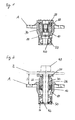
- the mounting arrangement consists of a receiving element 10 and an adjusting element 20, 30.
- the receiving element 10 and the adjusting element 20, 30 are connected to each other via a first thread pairing 12, 32.
- the one thread 12 of the first thread pairing is located on the inside of the receiving element 10.
- the other thread 32 is located on the outside of a threaded member 30, which forms the adjusting element 20, 30 together with a concomitant 20.
- Fig. 2 shows a sectional view of the installed between the components A and B mounting arrangement.
- the thread 52 of the receiving element 10 is preferably provided by means of a nut 50.
- the nut 50 is arranged in a holding chamber 16 of the receiving element 10.
- the nut 50 is maintained in the holding chamber 16 preferably via an interference fit between the walls or a retaining web and the walls of the holding chamber 16 or via the connection with the fastening screw 40.
- the threads 42 and 52 mating metric threads.
- the advantage of a fastening screw 40 with metric thread compared to the prior art is that in the metric screw the thread 42 can be pushed through the idler 20. As a result, pressing the worker on the fastening screw 40 during the screwing operation has no influence on the function of the fastening arrangement.
- the fastening screw 40 can be inserted into the fastening arrangement up to the nut 50. All pressure forces are transmitted from this point directly on the thread 52 to the nut 50.
- a fastening screw 40 with self-tapping thread 42 This would to fix within an opening of an end portion of the receiving element 10, which is formed instead of the holding chamber 16.
- the adjusting element 20, 30 consists of the threaded element 30, in the inner chamber 36 of the drag-20 is arranged.
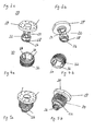
- b is the concomitant 20 shown.
- the idler 20 includes a contact portion 29 for abutment on the component B.
- the contact portion 29 has elevations in the direction of the component B, which dig into the component B. In this way, a positive connection between the contact portion 29 and the component B and thus a better grip between the mounting assembly and the component B is formed.
- the contact portion 29 has a central opening through which the fastening screw 40 is inserted.
- At least two drag webs 24 extend in the axial direction of the co-tug 20.
- the drag webs 24 are arranged opposite one another. In addition, they have an arcuate course, so that they constrict resiliently radially inwardly constricting a passage region of the fastening screw 40 by the Mitschlepper.
- the drag bars 24 are connected to one another via an annular structure. At least one radially outwardly projecting retaining lug 22 is arranged on the annular structure.
- the retaining lug 22 engages in a recess 34 adapted to it on the opposite inner side of the threaded element 30. By the retaining lug 22 engages in the recess 34, creates a rotationally fixed connection between the follower 20 and the threaded member 30.
- two retaining lugs 22 are arranged offset by 90 ° from the drag bars 24.
- guide grooves 38 are formed for the retaining lugs 22 on the inside of the threaded member 30.
- the retaining lugs 22 slide along the guide grooves 38 and then snap into the recesses 34. This is in the FIGS. 8 . 9, 11, 12 illustrated.
- the inner channel 36 of the threaded element 30 has a larger diameter than the male part of the towing member 20 to be received in the inner channel 36.
- the Recesses 34 in the lateral direction formed larger than the male retaining lugs 22 so that they can move therein.
- the oversizing of the inner channel 36 and the recesses 34 in comparison to the concomitant 20 leads to a floating mounting of the follower 20 on the threaded member 30.
- the concomitant 20 when inserting the fixing screw 40 within the threaded member 30 floating in the radial direction, ie laterally move to compensate for misalignments of the mounting screw 40.
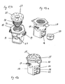
- Fig. 8 the section along the line BB Fig. 6 , It can be seen that despite a non-central arrangement of the concomitant 20, the installation of the fastening screw 40 is ensured.
- the inner channel 36 instead of the cylindrical shape in Fig. 4a, b an at least partially conical shape.
- the conical shape extends in such a way that the region of the inner channel 36 with the largest diameter adjoins the abutment portion 29 of the co-tug 20.
- the conical shape of the inner channel 36 ensures a tilting of the follower 20 within the threaded member 30.
- the follower 20 is axially tilted with respect to the longitudinal axis of the threaded member 30 within the threaded member 30 can be arranged.
- the inner channel 36 tapers, for example conically starting at the contact portion 29 to its end near the recesses 34. It is also conceivable that the inner channel 36 is formed as a double cone, starting at both ends of the inner channel 36 in the direction of a Tapered point near the inner channel center.
- the fastening arrangement comprises a transport lock 26. This serves to prevent a loosening of the fastening arrangement in the preassembled state.
- the transport lock 26 is disposed adjacent to the annular structure of the fellow tractor 20. It is formed by an oval-shaped ring 26, which is preferably secured by webs on the annular structure of the follower 20.
- the oval-shaped transport lock 26 comprises a region larger and a region of smaller diameter.
- the oval-shaped transport lock 26 is dimensioned such that the smaller diameter is smaller than the diameter of the fastening screw 40 and that the larger diameter is greater than the diameter of the fastening screw 40. Based on this dimensioning is carried out when screwing the fastening screw in the fly tractor 20 a pressing the oval shaped transport lock 26. This pressing of the smaller diameter portion is at the expense of the larger diameter region, so that the oval-shaped transport lock 26 after screwing the fastening screw 40 has an approximately circular shape.
- At least one radially outwardly projecting projection 28 is arranged.
- the projection 28 engages in channels, windows or depressions 14 on the inside of the receiving element 10. If the fastening screw 40 is screwed into the oval shaped transport lock 26, the area of smaller diameter is widened, while at the same time the area of larger diameter is reduced in diameter. This creates a radially inwardly directed deformation movement of the larger diameter portion so that the at least one projection 28 is released from the lock in the channel 14. After this has taken place, an adjustment of the adjusting element 20, 30 via the rotation of the fastening screw 40 can take place.
- the projections 28 are accessible from the outside and can be pressed radially inward. This can be done for example by a tool adapted to it. In this procedure, it is not necessary that this function is realized via the fastening screw 40.
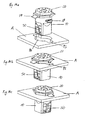
- FIGS. 13 a to c show the preparation of the mounting arrangement in the preassembled state.
- the nut 50 is inserted into the holding chamber 16.
- the adjusting element 20, 30 is screwed into the receiving element 10 until the oval-shaped transport lock 26 holds the adjusting element 20, 30 in the receiving element 10.
- the preassembled mounting assembly as shown in FIG Fig. 13 c is shown.
- the components A and B are preferably made of plastic.
- the component A consists for example of a glass fiber reinforced PP, while the component B consists of a softer plastic, such as a PP with talc. It is also preferable to manufacture the component A from metal or other materials.
- How to get in Fig. 14a can recognize the component A comprises a keyhole 90 in which the receiving element 10 can be received and fastened.
- the keyhole 90 is formed approximately complementary to the silhouette of the receiving element 10 within a first radial plane. In the first radial plane, for example, there are two holding projections 19. If a different number of holding projections 19 are provided, the shape of the keyhole 90 is correspondingly adapted to ensure insertion of the receiving element 10 into the keyhole 90.
- the inner diameter of the keyhole 90 is also smaller than the outer diameter of an upper flange or edge of the receiving element 10, so that the receiving element 10 can be held in a form-fitting manner in the component A.
- a spring element 17 and the flange of the receiving element 10 above the component A and the retaining projection 19 below the component A are arranged. If the receiving element 10 is pressed in the direction of the component A and subsequently rotated about its longitudinal axis, the retaining projections 19 are moved away from the openings 93 for insertion. Due to this rotation, a positive connection between the component A and the receiving element 10 is formed.
- the spring element 17 and the retaining projection 19 are arranged circumferentially offset by 90 ° to each other. Other angular arrangements are also conceivable, which can be realized in coordination with the component A.
- the receiving element 10 is rotated about its longitudinal axis.
- the receiving element 10 is rotated by an angle of 90 ° about its longitudinal axis, so that the prestressed by the surface of the component A spring elements 17 in the openings 93 snap (see Fig. 14c ).
- the spring elements 17 in the locked state are in Fig. 14c shown.
- the component A is clamped in this state between the flange of the receiving element 10 and the holding projection 19, so that a positive and non-positive connection between the component A and the receiving element 10 is present.
- the insertion and fastening of the receiving element in the component A is thus described with the following steps: a) alignment of keyhole 90 and receiving element 10 to each other, b) insertion of the receiving element 10 in the keyhole 90, c) rotating the receiving element 10 to its longitudinal axis, so that the component A is held between the flange and the retaining projection 19.
- the removal of the receiving element 10 can be summarized with the following steps: a) rotating the receiving element 10 about its longitudinal axis, whereby locking spring elements 17 are removed, b) aligning the receiving element 10 to the keyhole 90 and c) removing the receiving element 10 from the Keyhole 90.
Landscapes
- Engineering & Computer Science (AREA)
- General Engineering & Computer Science (AREA)
- Mechanical Engineering (AREA)
- Connection Of Plates (AREA)
- Snaps, Bayonet Connections, Set Pins, And Snap Rings (AREA)
- Devices For Conveying Motion By Means Of Endless Flexible Members (AREA)
- Bolts, Nuts, And Washers (AREA)
- Harvester Elements (AREA)
- Clamps And Clips (AREA)
Description
- Die vorliegende Erfindung betrifft eine Befestigungsanordnung zum Befestigen eines Bauteils B an einem Bauteil A mit selbsttätigem Ausgleich von Toleranzen im Abstand zwischen den beiden Bauteilen.
- Derartige Befestigungsanordnungen mit Toleranzausgleich sind in großer Vielfalt bekannt. Sie bestehen üblicherweise aus einer Verstellbuchse mit einem sogenannten Mitschleppabschnitt, der mit einer Befestigungsschraube eine Reibschlussverbindung eingehen kann. Beim Drehen der Befestigungsschraube wird daher die Verstellbuchse mitgedreht, bis sie sich an eines der beiden Bauteile anlegt, worauf dann beim Weiterdrehen der Befestigungsschraube und entsprechende Erhöhung des Drehmomentes die Reibschlussverbindung überwunden wird, so dass dann die beiden Bauteile durch die Befestigungsschraube über die Verstellbuchse miteinander verspannt werden können.
- Aus der europäischen Patentanmeldung
EP 1 780 424 ist eine derartige Toleranzausgleichsanordnung bekannt. Diese Anordnung umfasst ein einstückig ausgebildetes Aufnahmeelement und ein einstückig ausgebildetes Verstellelement. Das Aufnahmeelement hat einen Befestigungsabschnitt mit einem selbstfurchenden und/oder -formenden Gewinde, das zum Herstellen einer Schraubverbindung in das eine Bauteil einschraubbar ist, wobei die Schraubverbindung eine Kunststoff-in-Kunststoff-Schraubverbindung ist. -
DE 20 2006 012 493 U1 beschreibt eine Befestigungseinrichtung. Diese Befestigungseinrichtung setzt sich zusammen aus einer Basiseinheit, die aus einer am Bauteil A festlegbaren Blindnietmutter, einer Verstellgewindemutter und einem hülsenförmigen Käfig besteht, welcher die Verstellgewindemutter aufnimmt und mit der Blindnietmutter verbindet, einer Verstelleinheit, die aus einer Gewindehülse, einer Anlageplatte und einer Mitnehmerbuchse besteht, welche die Gewindehülse und die Anlageplatte verbindet, wobei die Gewindehülse der Verstelleinheit in die Verstellgewindemutter der Basiseinheit über eine erste Ge windepaarung einer ersten Gangrichtung einschraubbar ist, und einer Befestigungsschraube, die über eine zweite Gewindepaarung einer entgegengesetzten zweiten Gangrichtung in die am Bauteil A festgelegte Blindnietmutter einschraubbar ist und mit der Mitnehmerbuchse eine lösbare Mitschleppverbindung bildet, um beim Drehen der Befestigungsschraube die Verstelleinheit mitzudrehen und dadurch die Anlageplatte zwecks Toleranzausgleich in Anlage mit dem Bauteil B zu bewegen. - Der vorliegenden Erfindung liegt die Aufgabe zugrunde, eine Befestigungsanordnung mit selbsttätigem Toleranzausgleich der angegebenen Gattung so weiterzubilden, dass die Montage der Befestigungsanordnung vereinfacht wird.
- Die Befestigungsanordnung gemäß der vorliegenden Erfindung ist in Anspruch 1 definiert.
- Die Befestigungsanordnung dient dem Befestigen eines Bauteils B an einem Bauteil A mit selbsttätigem Ausgleich von Toleranzen im Abstand zwischen dem Bauteil B und dem Bauteil A. Die erfindungsgemäße Befestigungsanordnung weist die folgenden Merkmale auf: ein Aufnahmeelement und ein Verstellelement, das über eine erste Gewindepaarung einer ersten Gangrichtung mit dem Aufnahmeelement verschraubbar ist, während durch eine Öffnung von Aufnahmeelement und Verstellelement eine Befestigungsschraube einsetzbar ist, die über eine zweite Gewindepaarung einer der ersten entgegengesetzten zweiten Gangrichtung in das Aufnahmeelement einschraubbar und mit dem Verstellelement durch eine lösbare Mitschleppverbindung verbindbar ist, um beim Drehen der Befestigungsschraube das Verstellelement mitzudrehen und dadurch in Anlage mit dem Bauteil B zu bewegen, und deren Verstellelement aus einem innerhalb eines Gewindeelements drehfest und schwimmend angeordneten Mitschleppers besteht, so dass eine Fehlausrichtung der Befestigungsschraube beim Einsetzen in das Verstellelement ausgleichbar ist.
- In der erfindungsgemäßen Befestigungsanordnung ist das Verstellelement zweiteilig ausgebildet. Diese zweiteilige Ausbildung bestehend aus Gewindeelement und Mitschlepper gewährleistet einen Ausgleich von Montagefehlern beim Einsetzen der Befestigungsschraube in die Befestigungsanordnung. Da der Mitschlepper innerhalb des Gewindeelements schwimmend angeordnet ist, ist er in der Lage, bezogen auf seine Längsachse radiale bzw. laterale Ausgleichsbewegungen innerhalb des Gewindeelements auszuführen. Bei einer entsprechenden Formgestaltung von Gewindeelement und Mitschlepper besteht ebenfalls bevorzugt die Möglichkeit, dass eine winklige Ausgleichsbewegung durch den Mitschlepper innerhalb des Gewindeelements ausgeführt wird. Das bedeutet, dass bezogen auf die Längsachse des Gewindeelements die Längsachse des Mitschleppers eine nicht parallele geneigte Position einnehmen kann. Basierend auf dieser konstruktiven Grundlage ist die Befestigungsschraube mit einer gewissen Orientierungsungenauigkeit in die Befestigungsanordnung einsetzbar, ohne dass die Befestigungsschraube innerhalb der Befestigungsanordnung blockiert wird. Zudem wird der Toleranzausgleich durch die Befestigungsanordnung durch die fehlerhaft orientierte Befestigungsschraube nicht beeinträchtigt, da der Mitschlepper der Fehlorientierung der Befestigungsschraube innerhalb des Gewindeelements folgen kann. Er wird somit auch beim Drehen der Befestigungsschraube auf das Bauteil B zugestellt.
- Gemäß einer bevorzugten Ausführungsform der Befestigungsanordnung umgibt ein Innenkanal des Gewindeelements derart den Mitschlepper, dass der Mitschlepper innerhalb des Gewindeelements lateral, insbesondere in radialer Richtung bezogen auf das Gewindeelement, versetzbar ist. Es ist zudem ergänzend oder alternativ bevorzugt, dass sich der Innenkanal des Gewindeelements zumindest teilweise entlang seiner axialen Richtung verjüngt, so dass der Mitschlepper axial verkippt bezogen auf die Längsachse des Gewindeelements innerhalb des Gewindeelements anordenbar ist.
- Das Gewindeelement der Befestigungsanordnung ist mit einem entsprechend den Anforderungen geformten Innenkanal ausgestattet. Dieser Innenkanal umfasst beispielsweise eine zylindrische Form mit einem Innendurchmesser, der größer ausgebildet ist als der aufzunehmende Bereich des Mitschleppers. Dies gewährleistet, dass aufgrund der schwimmenden Lagerung des Mitschleppers innerhalb des Gewindeelements dieser in radialer Richtung bezogen auf das Gewindeelement innerhalb des Innenkanals verschiebbar ist. Auf diese Weise können die bereits oben angesprochenen Fehlorientierungen der Befestigungsschraube ausgeglichen werden. Gemäß einer weiteren Ausgestaltung ist ebenfalls ein Ausgleich von winkligen Fehlorientierungen der Befestigungsschraube durch eine winklige Orientierung des Mitschleppers möglich. In dieser Alternative verjüngt sich der Innenkanal zumindest in einem Teilbereich, so dass er eine konische Kontur aufweist. Der konischen Kontur folgend kann der Mitschlepper eine Fehlausrichtung der Befestigungsschraube ausgleichen, so dass auch auf diese Weise eine erleichterte Installation der Befestigungsanordnung unterstützt wird.
- Zur Gewährleistung der drehfesten Verbindung zwischen Mitschlepper und Gewindeelement weist der Mitschlepper bevorzugt mindestens eine in radialer Richtung vorstehende Haltenase auf, die in einer Vertiefung des Gewindeelements einrastbar ist.
- Zudem umfasst der Mitschlepper einer weiteren Ausführungsform eine oval geformte Transportsicherung, deren mindestens ein radial nach außen ragender Vorsprung an einer Innenseite des Aufnahmeelements verriegelbar ist. Diese oval geformte Transportsicherung ist gemäß einer Ausführungsform derart ausgebildet, dass beim Durchführen der Befestigungsschraube durch die oval geformte Transportsicherung der mindestens eine radial nach außen ragende Vorsprung durch eine radial nach innen gerichtete Verformungsbewegung der Transportsicherung aus der Innenseite des Aufnahmeelements entriegelbar ist.
- Die ovale Form der Transportsicherung ist somit an den Durchmesser der Befestigungsschraube derart angepasst, dass der im Durchmesser kleinere Bereich des Ovals kleiner ist als der Durchmesser der Befestigungsschraube und dass der im Durchmesser größere Bereich des Ovals größer ist als der Durchmesser der Befestigungsschraube. Durch diese Dimensionierung der oval geformten Transportsicherung und der Befestigungsschraube drückt die Befestigungsschraube beim Einsetzen in die oval geformte Transportsicherung den schmaleren Bereich auseinander und zieht auf diese Weise den breiteren Bereich des Ovals zusammen, so dass sich die Transportsicherung in eine annähernd runde Form verformt. Diese Verformungsbewegung bewegt den verriegelnden Vorsprung von der Innenseite des Aufnahmeelements weg, so dass das Verstellelement bestehend aus Mitschlepper und Gewindeelement innerhalb des Aufnahmeelements drehbar ist.
- Gemäß einer weiteren Ausgestaltung der vorliegenden Befestigungsanordnung umfasst der Mitschlepper zwei gegenüber voneinander angeordnete und in axiale Richtung des Mitschleppers verlaufende Schleppstege, die federnd radial nach innen ragend eine Durchgangsöffnung für die Befestigungsschraube verengen. Die Schleppstege sind vorzugsweise bogenförmig ausgebildet. Sie verbinden zudem die oval geformte Transportsicherung mit einem Anlageabschnitt des Mitschleppers.
- Wie oben bereits erwähnt worden ist, ist die Befestigungsschraube in ein Gewinde des Aufnahmeelements einschraubbar. Dieses Gewinde des Aufnahmeelements wird gemäß einer Ausführungsform durch eine Mutter bereitgestellt, die in eine Haltekammer des Aufnahmeelements einsetzbar ist. In dieser Haltekammer wird die Mutter beispielsweise durch Festklemmen befestigt. In Anpassung an die Befestigungsschraube ist es denkbar, dass die Mutter und die Befestigungsschraube jeweils ein zueinander passendes metrisches Gewinde aufweisen.
- Weitere vorteilhafte Ausgestaltungen der Erfindung gehen aus der folgenden Beschreibung, den Zeichnungen und anhängenden Ansprüchen hervor.
- Anhand der Zeichnungen werden Ausführungsbeispiele der Erfindung näher erläutert. Es zeigen:
- Fig. 1
- eine Schnittdarstellung durch die bevorzugte Befestigungsanordnung ohne Befestigungsschraube,
- Fig. 2
- eine Schnittdarstellung durch die bevorzugte Befestigungsanordnung mit Befestigungsschraube und installiert zwischen Bauteil A und B,
- Fig. 3 a und b
- eine perspektivische Ansichten des Mitschleppers,
- Fig. 4 a und b
- eine perspektivische Ansicht des Gewindeelements,
- Fig. 5 a und b
- eine perspektivische Ansichten des Verstellelements bestehend aus Gewindeelement und Mitschlepper,
- Fig. 6
- eine Seitenansicht der Befestigungsanordnung,
- Fig. 7
- ein Schnitt entlang der Linie A-A aus
Fig. 6 , - Fig. 8
- ein Schnitt entlang der Linie B-B aus
Fig. 6 , - Fig. 9
- eine Ansicht von unten des Verstellelement bestehend aus Mitschlepper und Gewindeelement,
- Fig. 10
- eine Ansicht von oben des Verstellelements bestehend aus Gewindeelement und Mitschlepper,
- Fig. 11
- ein Schnitt entlang der Linie A-A aus
Fig. 10 , - Fig. 12
- ein Schnitt entlang der Linie B-B aus
Fig. 10 , - Fig. 13 a bis c
- eine Zusammenbausequenz der Befestigungsanordnung mit Mutter und
- Fig. 14 a bis c
- eine Installationssequenz der Befestigungsanordnung in einem Schlüsselloch im Bauteil A.
- Wie in
Fig. 1 dargestellt ist, besteht die Befestigungsanordnung aus einem Aufnahmeelement 10 und einem Verstellelement 20, 30. Das Aufnahmeelement 10 und das Verstellelement 20, 30 sind über eine erste Gewindepaarung 12, 32 miteinander verbunden. Das eine Gewinde 12 der ersten Gewindepaarung befindet sich an der Innenseite des Aufnahmeelements 10. Das andere Gewinde 32 befindet sich an der Außenseite eines Gewindeelements 30, das gemeinsam mit einem Mitschlepper 20 das Verstellelement 20, 30 bildet. -
Fig. 2 zeigt eine Schnittdarstellung der zwischen den Bauteilen A und B installierten Befestigungsanordnung. Durch das Einschrauben einer Befestigungsschraube 40 in die Befestigungsanordnung verlängert sich die Befestigungsanordnung soweit, bis ein Abstand S zwischen den Bauteilen A und B ausgeglichen ist. Beim Einschrauben der Befestigungsschraube 40 in ein Gewinde 52 des Aufnahmeelements 10 wird das Verstellelement 20, 30 aus dem Aufnahmeelement 10 herausgeschraubt. Diese selbsttätige Verstellbewegung der Befestigungsanordnung basiert darauf, dass die Gewindepaarung eines Gewindes 42 der Befestigungsschraube 40 und eines Gewindes 52 des Aufnahmeelements 10 eine der Gewindepaarung 12, 32 entgegengesetzte Gangrichtung aufweist. - Das Gewinde 52 des Aufnahmeelements 10 wird bevorzugt mit Hilfe einer Mutter 50 bereitgestellt. Die Mutter 50 ist in einer Haltekammer 16 des Aufnahmeelements 10 angeordnet. Gehalten wird die Mutter 50 in der Haltekammer 16 vorzugsweise über einen Presssitz zwischen den Wänden oder einem Haltesteg und den Wänden der Haltekammer 16 oder über die Verbindung mit der Befestigungsschraube 40. Gemäß einer Ausführungsform vorliegender Erfindung sind die Gewinde 42 und 52 zueinander passende metrische Gewinde. Der Vorteil einer Befestigungsschraube 40 mit metrischem Gewinde im Vergleich zum Stand der Technik besteht darin, dass bei der metrischen Verschraubung das Gewinde 42 durch den Mitschlepper 20 durchgesteckt werden kann. Hierdurch hat ein Drücken des Werkers auf die Befestigungsschraube 40 während des Schraubvorgangs keinen Einfluss auf die Funktion der Befestigungsanordnung. Die Befestigungsschraube 40 kann bis zur Mutter 50 in die Befestigungsanordnung eingesteckt werden. Alle Druckkräfte werden ab diesem Zeitpunkt direkt über das Gewinde 52 an die Mutter 50 übertragen.
- Gemäß einer weiteren nicht dargestellten Ausführungsform ist es ebenfalls bevorzugt, eine Befestigungsschraube 40 mit selbstschneidendem Gewinde 42 einzusetzen. Diese würde sich innerhalb einer Öffnung eines Endbereichs des Aufnahmeelements 10 befestigen, der anstelle der Haltekammer 16 ausgebildet ist.
- Das Verstellelement 20, 30 besteht aus dem Gewindeelement 30, in dessen Innenkammer 36 der Mitschlepper 20 angeordnet ist. In den
Figuren 3a, b ist der Mitschlepper 20 dargestellt. Der Mitschlepper 20 umfasst einen Anlageabschnitt 29 zur Anlage am Bauteil B. Der Anlageabschnitt 29 weist Erhöhungen in Richtung des Bauteils B auf, die sich ins Bauteil B eingraben. Auf diese Weise bildet sich ein Formschluss zwischen dem Anlageabschnitt 29 und dem Bauteil B und somit ein besserer Halt zwischen der Befestigungsanordnung und dem Bauteil B heraus. Zudem weist der Anlageabschnitt 29 eine zentrale Öffnung auf, durch die die Befestigungsschraube 40 eingesetzt wird. - Unterhalb des Anlageabschnitts 29 erstrecken sich in axialer Richtung des Mitschleppers 20 mindestens zwei Schleppstege 24. Die Schleppstege 24 sind gegenüber voneinander angeordnet. Zudem weisen sie einen bogenförmigen Verlauf auf, so dass sie federnd radial nach innen ragend einen Durchgangsbereich der Befestigungsschraube 40 durch den Mitschlepper verengen.
- An ihrem dem Anlageabschnitt 29 abgewandten Ende sind die Schleppstege 24 über eine ringförmige Struktur miteinander verbunden. An der ringförmigen Struktur ist mindestens eine in radialer Richtung nach außen vorstehende Haltenase 22 angeordnet. Die Haltenase 22 greift in eine an sie angepasste Vertiefung 34 an der gegenüberliegenden Innenseite des Gewindeelements 30 ein. Indem die Haltenase 22 in der Vertiefung 34 einrastet, entsteht eine drehfeste Verbindung zwischen dem Mitschlepper 20 und dem Gewindeelement 30. Bevorzugt sind zwei Haltenasen 22 um 90° versetzt von den Schleppstegen 24 angeordnet.
- Um ein einfacheres und lagegenaues Einsetzen des Mitschleppers 20 in das Gewindeelement 30 zu gewährleisten, sind Führungsnuten 38 für die Haltenasen 22 an der Innenseite des Gewindeelements 30 ausgebildet. Wird der Mitschlepper 20 an das Gewindeelement 30 eingesetzt, gleiten die Haltenasen 22 entlang der Führungsnuten 38 und rasten dann in den Vertiefungen 34 ein. Dies ist in den
Figuren 8 ,9, 11, 12 veranschaulicht. - Der Innenkanal 36 des Gewindeelements 30 weist einen größeren Durchmesser als der im Innenkanal 36 aufzunehmende Teil des Mitschleppers 20 auf. In gleicher Weise sind die Vertiefungen 34 in lateraler Richtung größer ausgebildet als die aufzunehmenden Haltenasen 22, so dass sich diese darin bewegen können. Die Überdimensionierung des Innenkanals 36 und der Vertiefungen 34 im Vergleich zum Mitschlepper 20 führt zu einer schwimmenden Lagerung des Mitschleppers 20 am Gewindeelement 30. Auf dieser Grundlage kann sich der Mitschlepper 20 beim Einsetzen der Befestigungsschraube 40 innerhalb des Gewindeelements 30 schwimmend in radialer Richtung, also lateral, verschieben, um Fehlausrichtungen der Befestigungsschraube 40 auszugleichen. In
Fig. 8 , dem Schnitt entlang der Linie B-B ausFig. 6 , ist erkennbar, dass trotz einer nicht mittigen Anordnung des Mitschleppers 20 die Installation der Befestigungsschraube 40 gewährleistet ist. - Gemäß einer weiteren nicht dargestellten Ausführungsform hat der Innekanal 36 anstelle der zylindrischen Form in
Fig. 4a, b eine zumindest teilweise konische Form. Die konische Form verläuft derart, dass der Bereich des Innenkanals 36 mit dem größten Durchmesser an den Anlageabschnitt 29 des Mitschleppers 20 angrenzt. Die konische Form des Innenkanals 36 gewährleistet ein Verkippen des Mitschleppers 20 innerhalb des Gewindeelements 30. Auf diese Weise ist der Mitschlepper 20 axial verkippt bezogen auf die Längsachse des Gewindeelements 30 innerhalb des Gewindeelements 30 anordenbar. Zu diesem Zweck verjüngt sich der Innenkanal 36 beispielsweise konisch beginnend am Anlageabschnitt 29 bis zu seinem Ende nahe den Vertiefungen 34. Es ist ebenfalls denkbar, dass der Innenkanal 36 als Doppelkonus ausgebildet ist, der sich beginnend an beiden Enden des Innenkanals 36 in Richtung auf einen Punkt nahe der Innenkanalmitte verjüngt. - Mit Hilfe der oben beschriebenen Konstruktionen wird eine schwimmende Anordnung des Mitschleppers 20 im Gewindeelement 30 realisiert, durch die der Mitschlepper 20 lateral versetzbar und/oder axial verkippbar in Bezug auf das Gewindeelement 30 angeordnet ist.
- Gemäß einer weiteren bevorzugten Ausführungsform umfasst die Befestigungsanordnung eine Transportsicherung 26. Diese dient dazu, ein Lösen der Befestigungsanordnung im vormontierten Zustand zu verhindern. Die Transportsicherung 26 ist angrenzend an die ringförmige Struktur des Mitschleppers 20 angeordnet. Sie wird durch einen oval geformten Ring 26 gebildet, der vorzugsweise über Stege an der ringförmigen Struktur des Mitschleppers 20 befestigt ist.
- Die oval geformten Transportsicherung 26 umfasst einen Bereich größeren und einen Bereich kleineren Durchmessers. Die oval geformte Transportsicherung 26 ist derart dimensioniert, dass der kleinere Durchmesser kleiner ist als der Durchmesser der Befestigungsschraube 40 und dass der größere Durchmesser größer ist als der Durchmesser der Befestigungsschraube 40. Basierend auf dieser Dimensionierung erfolgt beim Einschrauben der Befestigungsschraube in den Mitschlepper 20 ein Aufdrücken der oval geformten Transportsicherung 26. Dieses Aufdrücken des Bereichs kleineren Durchmessers erfolgt auf Kosten des Bereichs größeren Durchmessers, so dass die oval geformte Transportsicherung 26 nach dem Einschrauben der Befestigungsschraube 40 eine annähernd kreisförmige Gestalt aufweist.
- Im Bereich größeren Durchmessers der Transportsicherung 26 ist mindestens ein radial nach außen ragender Vorsprung 28 angeordnet. Zum Herstellen einer Transportsicherung greift der Vorsprung 28 in Kanäle, Fenster oder Vertiefungen 14 an der Innenseite des Aufnahmeelements 10 ein. Wird die Befestigungsschraube 40 in die oval geformte Transportsicherung 26 eingeschraubt, wird der Bereich kleineren Durchmessers aufgeweitet, während sich gleichzeitig der Bereich größeren Durchmessers in seinem Durchmesser verkleinert. Dies erzeugt eine radial nach innen gerichtete Verformungsbewegung des Bereichs größeren Durchmessers, so dass der mindestens eine Vorsprung 28 aus der Verriegelung in dem Kanal 14 gelöst wird. Nachdem dies erfolgt ist, kann ein Verstellen des Verstellelements 20, 30 über das Drehen der Befestigungsschraube 40 stattfinden.
- Es ist ebenfalls denkbar, die oval geformte Transportsicherung 26 von außen über die Kanäle 14 zu lösen. Über die Kanäle 14 durch das Aufnahmeelement 10 sind die Vorsprünge 28 von außen zugänglich und können radial nach innen gedrückt werden. Dies kann beispielsweise durch ein darauf angepasstes Werkzeug erfolgen. Bei diesem Vorgehen ist es nicht erforderlich, dass diese Funktion über die Befestigungsschraube 40 realisiert wird.
- Die
Figuren 13 a bis c zeigen die Herstellung der Befestigungsanordnung im vormontierten Zustand. Zu diesem Zweck wird die Mutter 50 in die Haltekammer 16 eingesetzt. Danach wird das Verstellelement 20, 30 in das Aufnahmeelement 10 eingeschraubt, bis die oval geformte Transportsicherung 26 das Verstellelement 20, 30 in dem Aufnahmeelement 10 hält. Nachdem dieser Schritt abgeschlossen ist, liegt die vormontierte Befestigungsanordnung vor, wie sie inFig. 13 c dargestellt ist. - Die Bauteile A und B bestehen vorzugsweise aus Kunststoff. Das Bauteil A besteht beispielsweise aus einem glasfaserverstärkten PP, während das Bauteil B aus einem weicheren Kunststoff, beispielsweise einem PP mit Talkum besteht. Es ist ebenfalls bevorzugt, das Bauteil A aus Metall oder anderen Werkstoffen herzustellen. Wie man in
Fig. 14a erkennen kann, umfasst das Bauteil A ein Schlüsselloch 90, in dem das Aufnahmeelement 10 aufnehmbar und befestigbar ist. Das Schlüsselloch 90 ist annähernd komplementär zur Silhouette des Aufnahmeelements 10 innerhalb einer ersten Radialebene ausgebildet. In der ersten Radialebene liegen beispielsweise zwei Haltevorsprünge 19. Ist eine andere Anzahl von Haltevorsprüngen 19 vorgesehen, ist die Form des Schlüsselloch 90 entsprechend angepasst, um ein Einsetzen des Aufnahmeelements 10 in das Schlüsselloch 90 zu gewährleisten. Der innere Durchmesser des Schlüssellochs 90 ist zudem kleiner als der Außendurchmesser eines oberen Flansches oder Rands des Aufnahmeelements 10, damit das Aufnahmeelement 10 formschlüssig im Bauteil A gehalten werden kann. - Nach dem Einsetzen des Aufnahmeelements 10 in das Schlüsselloch 90 in passender Ausrichtung, sind ein Federelement 17 und der Flansch des Aufnahmeelements 10 oberhalb des Bauteils A und der Haltevorsprung 19 unterhalb des Bauteils A angeordnet. Wird das Aufnahmeelement 10 in Richtung des Bauteils A gedrückt und nachfolgend um seine Längsachse gedreht, werden die Haltevorsprünge 19 von den Öffnungen 93 zum Einsetzen weg bewegt. Aufgrund dieser Drehung entsteht eine formschlüssige Verbindung zwischen dem Bauteil A und dem Aufnahmeelement 10.
- Wie in
Fig. 14a zu erkennen ist, sind das Federelement 17 und der Haltevorsprung 19 umfänglich um 90° versetzt zueinander angeordnet. Andere winklige Anordnungen sind ebenfalls denkbar, die in Abstimmung mit dem Bauteil A realisierbar sind. Nach dem Einsetzen des Aufnahmeelements 10 in das Schlüsselloch 90, wobei die Haltevorsprünge 19 in Ausrichtung mit der Öffnung 93 sind, wie es inFig. 14b gezeigt ist, wird das Aufnahmeelement 10 um seine Längsachse gedreht. Vorzugsweise wird das Aufnahmeelement 10 um einen Winkel von 90° um seine Längsachse gedreht, so dass die durch die Oberfläche des Bauteils A vorgespannten Federelemente 17 in die Öffnungen 93 einschnappen (sieheFig. 14c ). Es ist ebenfalls möglich, Vertiefungen oder Verriegelungsöffnungen auf/in der Oberfläche des Bauteils A vorzusehen, die nicht mit den Einsetzöffnungen 93 der Haltevorsprünge 19 identisch sind. Diese Vertiefungen oder Verriegelungsöffnungen (nicht gezeigt) dienen dann lediglich dem Verriegeln/Einschnappen der Federelemente 17 und nicht dem Einsetzen der Haltevorsprünge 19. - Die Federelemente 17 im verriegelten Zustand sind in
Fig. 14c dargestellt. Das Bauteil A ist in diesem Zustand zwischen dem Flansch des Aufnahmeelements 10 und dem Haltevorsprung 19 eingeklemmt, so dass eine form- und kraftschlüssige Verbindung zwischen dem Bauteil A und dem Aufnahmeelement 10 vorliegt. - In Zusammenfassung der obigen Beschreibung ist somit das Einsetzen und Befestigen des Aufnahmeelements im Bauteil A mit folgenden Schritten beschreibbar: a) Ausrichten von Schlüsselloch 90 und Aufnahmeelement 10 zueinander, b) Einsetzen des Aufnahmeelements 10 in das Schlüsselloch 90, c) Drehen des Aufnahmeelements 10 um seine Längsachse, so dass das Bauteil A zwischen dem Flansch und dem Haltevorsprung 19 gehalten wird. In gleicher Weise kann das Entfernen des Aufnahmeelements 10 mit folgenden Schritten zusammengefasst werden: a) Drehen des Aufnahmeelements 10 um seine Längsachse, wodurch verriegelnde Federelemente 17 entfernt werden, b) Ausrichten des Aufnahmeelements 10 zum Schlüsselloch 90 und c) Entfernen des Aufnahmeelements 10 aus dem Schlüsselloch 90.
Claims (12)
- Befestigungsanordnung zum Befestigen eines Bauteils B an einem Bauteil A mit selbsttätigem Ausgleich von Toleranzen im Abstand (S) zwischen dem Bauteil B und dem Bauteil A, die die folgenden Merkmale aufweist:a. ein Aufnahmeelement (10) und ein Verstellelement (20, 30), das über eine erste Gewindepaarung (12, 32) einer ersten Gangrichtung mit dem Aufnahmeelement (10) verschraubbar ist, währendb. durch eine Öffnung von Aufnahmeelement (10) und Verstellelement (20, 30) eine Befestigungsschraube (40) einsetzbar ist, die über eine zweite Gewindepaarung (42, 52) einer der ersten entgegengesetzten zweiten Gangrichtung in das Aufnahmeelement (10) einschraubbar und mit dem Verstellelement (20, 30) durch eine lösbare Mitschleppverbindung (24) verbindbar ist, um beim Drehen der Befestigungsschraube (40) das Verstellelement (20, 30) mitzudrehen und dadurch in Anlage mit dem Bauteil B zu bewegen, und derenc. Verstellelement (20, 30) aus einem innerhalb eines Gewindeelements (30) drehfest angeordneten Mitschleppers (20) besteht, dadurch gekennzeichnet, dass der Mitschlepper (20) schwimmend innerhalb des Gewindeelements (30) angeordnet ist, so dass eine Fehlausrichtung der Befestigungsschraube (40) beim Einsetzen in das Verstellelement (20, 30) ausgleichbar ist.
- Befestigungsanordnung gemäß Anspruch 1, in der der Mitschlepper (20) durch seine schwimmende Anordnung lateral versetzbar und/oder axial verkippbar in Bezug auf das Gewindeelement (30) ist.
- Befestigungsanordnung gemäß einem der vorhergehenden Ansprüche, in der ein Innenkanal (36) des Gewindeelements (30) derart den Mitschlepper (20) umgibt, dass der Mitschlepper (20) innerhalb des Gewindeelements (30) lateral, insbesondere in radialer Richtung bezogen auf das Gewindeelement (30), versetzbar ist, und/oder in der sich der Innenkanal des Gewindelements (30) zumindest teilweise entlang seiner axialen Richtung verjüngt, so dass der Mitschlepper (20) axial verkippt bezogen auf die Längsachse des Gewindeelements (30) innerhalb des Gewindeelements (30) anordenbar ist.
- Befestigungsanordnung gemäß einem der vorhergehenden Ansprüche, deren Mitschlepper (20) mindestens eine in radialer Richtung vorstehende Haltenase (22) aufweist, die in einer Vertiefung (34) des Gewindeelements (30) einrastbar ist.
- Befestigungsanordnung gemäß einem der vorhergehenden Ansprüche, deren Mitschlepper (20) eine oval geformte Transportsicherung (26) umfasst, deren mindestens ein radial nach außen ragender Vorsprung (28) an einer Innenseite des Aufnahmeelements (10) verriegelbar ist.
- Befestigungsanordnung gemäß Anspruch 5, deren oval geformte Transportsicherung (26) derart ausgebildet ist, dass beim Durchführen der Befestigungsschraube (40) durch die oval geformte Transportsicherung (26) der mindestens eine radial nach außen ragende Vorsprung (28) durch eine radial nach innen gerichtete Verformungsbewegung der Transportsicherung (26) entriegelbar ist.
- Befestigungsanordnung gemäß einem der vorhergehenden Ansprüche, deren Mitschlepper (20) zwei gegenüber voneinander angeordnete und in axialer Richtung des Mitschleppers (20) verlaufende Schleppstege (24) umfasst, die federnd radial nach innen ragend einen Durchgangsbereich für die Befestigungsschraube (40) verengen.
- Befestigungsanordnung gemäß Anspruch 7, deren Schleppstege (24) bogenförmig ausgebildet sind und die oval geformte Transportsicherung (26) mit einem Anlageabschnitt (29) des Mitschleppers (20) verbinden.
- Befestigungsanordnung gemäß einem der vorhergehenden Ansprüche, deren Aufnahmeelement (10) eine Haltekammer (16) aufweist, in die eine Mutter (50) mit einem passenden Gewinde (52) zur Befestigungsschraube (40) einsetzbar ist.
- Befestigungsanordnung gemäß einem der vorhergehenden Ansprüche, die eine Befestigungsschraube (40) und eine Mutter (50) aufweist.
- Befestigungsanordnung gemäß Anspruch 10, in der Mutter (50) und Befestigungsschraube (40) jeweils ein zueinander passendes metrisches Gewinde aufweisen.
- Bauteil A in Kombination mit einer Befestigungsanordnung gemäß einem der vorhergehenden Ansprüche, während das Bauteil A ein Schlüsselloch (90) aufweist, in dem das Aufnahmeelement (10) der Befestigungsanordnung festlegbar ist.
Applications Claiming Priority (2)
| Application Number | Priority Date | Filing Date | Title |
|---|---|---|---|
| DE202008011318U DE202008011318U1 (de) | 2008-08-28 | 2008-08-28 | Befestigungsanordnung mit Toleranzausgleich |
| PCT/EP2009/005496 WO2010022841A1 (de) | 2008-08-28 | 2009-07-29 | Befestigungsanordnung mit toleranzausgleich |
Publications (2)
| Publication Number | Publication Date |
|---|---|
| EP2318723A1 EP2318723A1 (de) | 2011-05-11 |
| EP2318723B1 true EP2318723B1 (de) | 2012-01-18 |
Family
ID=39942608
Family Applications (1)
| Application Number | Title | Priority Date | Filing Date |
|---|---|---|---|
| EP09777522A Active EP2318723B1 (de) | 2008-08-28 | 2009-07-29 | Befestigungsanordnung mit toleranzausgleich |
Country Status (8)
| Country | Link |
|---|---|
| US (1) | US8864432B2 (de) |
| EP (1) | EP2318723B1 (de) |
| JP (1) | JP5393787B2 (de) |
| CN (1) | CN102138011B (de) |
| AT (1) | ATE542054T1 (de) |
| DE (1) | DE202008011318U1 (de) |
| ES (1) | ES2381158T3 (de) |
| WO (1) | WO2010022841A1 (de) |
Families Citing this family (59)
| Publication number | Priority date | Publication date | Assignee | Title |
|---|---|---|---|---|
| DE102011001052A1 (de) * | 2011-03-03 | 2012-09-06 | Böllhoff Verbindungstechnik GmbH | Befestigungseinrichtung mit Toleranzausgleich |
| US9133869B2 (en) * | 2011-08-01 | 2015-09-15 | Elringklinger Ag | Shielding device with a shielding element and at least one temperature and oscillation-decoupled fastening device |
| DE102012202654B3 (de) * | 2011-11-16 | 2013-04-25 | C. Rob. Hammerstein Gmbh & Co. Kg | Verfahren und Befestigungselement zur Montage eines Fahrzeugsitzes |
| DE102012102906A1 (de) * | 2012-04-03 | 2013-10-10 | Böllhoff Verbindungstechnik GmbH | Befestigungsanordnung mit Toleranzausgleich sowie Verfahren zur Vormontage und Montage |
| DE102012007996A1 (de) * | 2012-04-20 | 2013-10-24 | GM Global Technology Operations LLC (n. d. Gesetzen des Staates Delaware) | Toleranzausgleichsanordnung mit Ausdrehsicherung |
| DE202012102440U1 (de) * | 2012-07-03 | 2013-10-07 | Jörg Schwarzbich | Toleranzausgleichselement |
| US9644667B2 (en) | 2012-10-18 | 2017-05-09 | Apple Inc. | Floating fasteners |
| DE102013109036A1 (de) * | 2013-08-21 | 2015-02-26 | Heiko Schmidt | Verfahren zum Verbinden von Bauteilen sowie Baugruppe |
| DE102013216716B4 (de) | 2013-08-22 | 2023-05-04 | Witte Automotive Gmbh | Toleranzausgleichsvorrichtung |
| DE202013105469U1 (de) * | 2013-12-02 | 2015-03-03 | Makita Corporation | Befestigungsanordnung, tragbares Arbeitsgerät zum Befestigen eines ersten Gehäuseteils an einem zweiten Gehäuseteil |
| AT515304B1 (de) * | 2014-03-07 | 2015-08-15 | Facc Ag | Vorrichtung zur Verbindung eines Strukturelements sowie Strukturelement |
| DE102014006088B4 (de) | 2014-04-26 | 2024-10-02 | Witte Automotive Gmbh | Toleranzausgleichselement |
| EP2982580B1 (de) | 2014-08-05 | 2018-08-01 | MAGNA STEYR Fahrzeugtechnik AG & Co KG | Verfahren zur Herstellung eines Kraftfahrzeuges und Kraftfahrzeug |
| DE102014221266A1 (de) * | 2014-10-20 | 2016-04-21 | Böllhoff Verbindungstechnik GmbH | Schnellbefestiger, Verfahren zur Verbindung von zwei Bauteilen mittels des Schnellbefestigers und Herstellungsverfahren dafür |
| FR3029980B1 (fr) * | 2014-12-15 | 2017-01-13 | Snecma | Systeme de reparation d'une attache equipant une paroi de reacteur |
| ES2575052B1 (es) * | 2014-12-23 | 2017-04-06 | Illinois Tools Works Inc. | Tuerca de compensación |
| DE102015204120B4 (de) * | 2015-03-06 | 2022-08-25 | Zf Friedrichshafen Ag | Befestigungsvorrichtung zum Befestigen einer Leiterplatte an einem Träger, Schaltungsvorrichtung und Verfahren zum Befestigen einer Leiterplatte an einem Träger |
| WO2016142964A1 (en) * | 2015-03-06 | 2016-09-15 | Aoyama Seisakusho Co., Ltd. | Fastening tool with earth function |
| DE102015206419B4 (de) * | 2015-04-10 | 2025-11-20 | Ford Global Technologies, Llc | Anordnung zur Befestigung eines Bauteils an einer Halterung |
| KR101653576B1 (ko) * | 2015-08-12 | 2016-09-05 | (주)대한솔루션 | 자동차의 대시 패널 인슐레이션용 마운팅 클립 |
| CN106711574B (zh) * | 2015-11-13 | 2023-09-22 | 安弗施技术公司 | 一种天线的安装部件、支架、安装总成和安装方法 |
| DE102015122744A1 (de) | 2015-12-23 | 2017-06-29 | Böllhoff Verbindungstechnik GmbH | Verstellbare Distanzhülse |
| DE102016208179A1 (de) * | 2016-05-12 | 2017-11-16 | Springfix-Befestigungstechnik Gmbh | Vorrichtung zum Festlegen an einem Bauteil |
| US20190293099A1 (en) * | 2016-06-14 | 2019-09-26 | Illinois Tool Works Inc. | Rotationally-Constrainable Compensation Nut Fastener Assembly |
| CN107701608B (zh) * | 2016-08-08 | 2021-09-24 | 舍弗勒技术股份两合公司 | 同步器和用于同步器的预同步滑块 |
| DE102016118138B4 (de) * | 2016-09-26 | 2020-04-16 | Benteler Automobiltechnik Gmbh | Toleranzausgleichselement zum Ausgleichen eines Abstandes zwischen einem Instrumententräger und einem Karosseriebauteil eines Fahrzeugs |
| DE102016118640B4 (de) * | 2016-09-30 | 2024-10-17 | Witte Automotive Gmbh | Federelement |
| FR3061118B1 (fr) | 2016-12-23 | 2019-06-14 | A. Raymond Et Cie | Dispositif d'ecartement pouvant etre dispose entre deux supports |
| DE102017100442A1 (de) * | 2017-01-11 | 2018-07-12 | Lisi Automotive Mecano Gmbh | Käfigmutter |
| US11572909B2 (en) | 2017-08-29 | 2023-02-07 | Illinois Tool Works Inc. | Tolerance compensation fastening apparatuses with extended tolerance compensation and simpler and quicker fastening |
| DE102017124470A1 (de) * | 2017-10-19 | 2019-04-25 | Böllhoff Verbindungstechnik GmbH | Toleranzausgleichsanordnung |
| DE102017124809A1 (de) | 2017-10-24 | 2019-04-25 | Böllhoff Verbindungstechnik GmbH | Toleranzausgleichsanordnung |
| CN107869508A (zh) * | 2017-10-31 | 2018-04-03 | 平湖市万顺达机械有限公司 | 一种复合型螺栓结构 |
| DE102017130605A1 (de) * | 2017-12-19 | 2019-06-19 | Böllhoff Verbindungstechnik GmbH | Toleranzausgleichsanordnung mit Klemmsicherung |
| DE102017131235A1 (de) * | 2017-12-22 | 2019-06-27 | Witte Automotive Gmbh | Toleranzausgleichsvorrichtung |
| DE102018102291A1 (de) * | 2018-02-01 | 2019-08-01 | Witte Automotive Gmbh | Vorrichtung zum Ausgleichen von Toleranzen |
| CN110388371A (zh) * | 2018-04-18 | 2019-10-29 | 伊利诺斯工具制品有限公司 | 一种螺母紧固夹和螺母紧固夹组件 |
| DE102019113243A1 (de) * | 2018-06-15 | 2019-12-19 | Illinois Tool Works Inc. | Platzsparendes toleranzausgleichendes befestigungssystem |
| DE102018130391B4 (de) * | 2018-11-29 | 2023-10-26 | Witte Automotive Gmbh | Toleranzausgleichsvorrichtung mit kopplungsmittel |
| DE102019206750B4 (de) * | 2019-05-09 | 2025-10-09 | Witte Automotive Gmbh | Vorrichtung zum Ausgleichen von Toleranzen zwischen einem ersten Bauteil und einem zweiten Bauteil |
| CN112049850A (zh) * | 2019-06-06 | 2020-12-08 | 伊利诺斯工具制品有限公司 | 紧固件 |
| CN110306889B (zh) * | 2019-07-29 | 2024-07-23 | 上海佳慕汽车零部件股份有限公司 | 一种隐藏把手的安装结构及其安装方法 |
| DE102020204180A1 (de) * | 2020-03-31 | 2021-09-30 | Witte Automotive Gmbh | Befestigungselement |
| CN111503117B (zh) * | 2020-05-09 | 2024-10-25 | 宾科精密部件(中国)有限公司 | 紧固机构及其组装方法 |
| DE102020133763A1 (de) | 2020-12-16 | 2022-06-23 | Böllhoff Verbindungstechnik GmbH | Toleranzausgleichsanordnung |
| DE102020216324A1 (de) * | 2020-12-18 | 2022-06-23 | Witte Automotive Gmbh | Vorrichtung zum Ausgleichen von Toleranzen zwischen einem ersten Bauteil und einem zweiten Bauteil und Anordnung zum Ausgleichen von Toleranzen |
| DE102021102205B3 (de) | 2021-02-01 | 2022-05-19 | Audi Aktiengesellschaft | Entkopplungselement |
| CN115013400B (zh) * | 2021-03-04 | 2024-03-22 | 宾科精密部件(中国)有限公司 | 隐藏式紧固机构及方法 |
| DE102021105786A1 (de) * | 2021-03-10 | 2022-09-15 | Böllhoff Verbindungstechnik GmbH | Toleranzausgleichsanordnung |
| DE102021203130A1 (de) | 2021-03-29 | 2022-09-29 | Continental Automotive Technologies GmbH | Schraubenhalterung und Halteanordnung |
| DE102021205410A1 (de) * | 2021-05-27 | 2022-12-01 | Witte Automotive Gmbh | Vorrichtung zum Ausgleichen von Toleranzen zwischen zwei miteinander zu verbindenden Bauteilen |
| PL4095395T3 (pl) * | 2021-05-27 | 2023-12-18 | Böllhoff Verbindungstechnik GmbH | Element nastawczy, pierwszy komponent z elementem nastawczym, konstrukcja łącząca zawierająca pierwszy komponent, sposób wytwarzania elementu nastawczego i sposób połączenia |
| DE102021116282A1 (de) * | 2021-06-23 | 2022-12-29 | Böllhoff Verbindungstechnik GmbH | Toleranzausgleichselement, Bauteil mit dem Toleranzausgleichselement sowie dazugehörige Verbindung zwischen einem ersten und einem zweiten Bauteil, Herstellungsverfahren und Verbindungsverfahren |
| DE102021206692A1 (de) * | 2021-06-28 | 2022-12-29 | Springfix-Befestigungstechnik Gesellschaft mit beschränkter Haftung | Vorrichtung zur Befestigung an einem Bauteil |
| DE102021129784A1 (de) | 2021-11-16 | 2023-05-17 | Audi Aktiengesellschaft | Toleranzausgleichsanordnung, Batterie und Verfahren zum Bereitstellen eines Toleranzausgleichs |
| JP7457395B2 (ja) | 2022-02-15 | 2024-03-28 | ヒロホー株式会社 | 連結具 |
| DE102022107018B4 (de) | 2022-03-24 | 2023-10-05 | Witte Automotive Gmbh | Toleranzausgleichsvorrichtung |
| CN116696916A (zh) * | 2023-07-17 | 2023-09-05 | 厦门恒耀金属有限公司 | 一种螺纹紧固调整组件 |
| CN116696901A (zh) * | 2023-07-31 | 2023-09-05 | 宁波德普隆汽车系统有限公司 | 一种分体式公差调节器 |
Family Cites Families (9)
| Publication number | Priority date | Publication date | Assignee | Title |
|---|---|---|---|---|
| WO2002010597A1 (en) * | 2000-07-28 | 2002-02-07 | Ozawa, Junzo | Fastening implement |
| DE102005037192A1 (de) | 2005-08-06 | 2007-02-08 | Witte-Velbert Gmbh & Co. Kg | Baukastenartig zusammengesetzte Verspannvorrichtung |
| DE202005016823U1 (de) * | 2005-10-26 | 2006-02-09 | Böllhoff Verbindungstechnik GmbH | Befestigungseinrichtung mit Toleranzausgleich |
| DE102006034463B3 (de) * | 2006-07-26 | 2008-01-10 | A. Raymond Et Cie | Vorrichtung zum Befestigen eines Anbauteiles und eines Trägerteiles in einem Abstand voneinander |
| DE202006012493U1 (de) * | 2006-08-14 | 2006-11-02 | Böllhoff Verbindungstechnik GmbH | Befestigungseinrichtung mit Toleranzausgleich |
| DE102007037242B4 (de) | 2006-08-14 | 2019-05-29 | Böllhoff Verbindungstechnik GmbH | Befestigungseinrichtung mit Toleranzausgleich |
| DE202007008152U1 (de) | 2007-06-11 | 2007-08-09 | Böllhoff Verbindungstechnik GmbH | Befestigungseinrichtung mit Toleranzausgleich |
| DE202007008154U1 (de) | 2007-06-11 | 2007-09-06 | Böllhoff Verbindungstechnik GmbH | Montageeinheit für eine Befestigungseinrichtung mit Toleranzausgleich |
| KR101086609B1 (ko) * | 2009-06-01 | 2011-11-23 | 현대자동차주식회사 | 카울 크로스바 마운팅 조립체 |
-
2008
- 2008-08-28 DE DE202008011318U patent/DE202008011318U1/de not_active Expired - Lifetime
-
2009
- 2009-07-29 JP JP2011524217A patent/JP5393787B2/ja active Active
- 2009-07-29 US US13/058,433 patent/US8864432B2/en active Active
- 2009-07-29 EP EP09777522A patent/EP2318723B1/de active Active
- 2009-07-29 CN CN200980133910.4A patent/CN102138011B/zh active Active
- 2009-07-29 AT AT09777522T patent/ATE542054T1/de active
- 2009-07-29 ES ES09777522T patent/ES2381158T3/es active Active
- 2009-07-29 WO PCT/EP2009/005496 patent/WO2010022841A1/de not_active Ceased
Also Published As
| Publication number | Publication date |
|---|---|
| ES2381158T3 (es) | 2012-05-23 |
| JP2012500949A (ja) | 2012-01-12 |
| DE202008011318U1 (de) | 2008-11-06 |
| EP2318723A1 (de) | 2011-05-11 |
| ATE542054T1 (de) | 2012-02-15 |
| JP5393787B2 (ja) | 2014-01-22 |
| US20120090146A1 (en) | 2012-04-19 |
| WO2010022841A1 (de) | 2010-03-04 |
| CN102138011B (zh) | 2013-11-06 |
| US8864432B2 (en) | 2014-10-21 |
| CN102138011A (zh) | 2011-07-27 |
Similar Documents
| Publication | Publication Date | Title |
|---|---|---|
| EP2318723A1 (de) | Befestigungsanordnung mit toleranzausgleich | |
| EP3698055B1 (de) | Toleranzausgleichsanordnung | |
| EP2003346B1 (de) | Befestigungseinrichtung mit Toleranzausgleich | |
| EP3717786B1 (de) | Toleranzausgleichsanordnung mit klemmsicherung | |
| EP2495453B1 (de) | Befestigungseinrichtung mit Toleranzausgleich | |
| DE102007037242B4 (de) | Befestigungseinrichtung mit Toleranzausgleich | |
| EP1979634B1 (de) | Montageeinheit für die befestigungsöse eines gurtschlosses | |
| EP3384167B1 (de) | Verstellbare distanzhülse | |
| EP3612740B1 (de) | Verstelleinheit und einstellverfahren für ein bauteil | |
| EP3209888B1 (de) | Schnellbefestiger, verfahren zur verbindung von zwei bauteilen mittels des schnellbefestigers und herstellungsverfahren dafür | |
| EP1744063A2 (de) | Toleranzausgleichsanordnung aus Kunststoff | |
| EP2082143B1 (de) | Kombination aus einer schraube, einer unterlegscheibe und einer hülse sowie verfahren zum herstellen einer solchen kombination | |
| DE202004016321U1 (de) | Zug-Druck-Stange | |
| DE202006012493U1 (de) | Befestigungseinrichtung mit Toleranzausgleich | |
| WO2020200776A1 (de) | Mehrteiliges verstellelement für eine toleranzausgleichsanordnung | |
| DE102021105786A1 (de) | Toleranzausgleichsanordnung | |
| DE102020213642A1 (de) | Vorrichtung zum Ausgleichen von Toleranzen und Anordnung | |
| EP4737748A1 (de) | Verbindungselement und verbindungsanordnung | |
| DE4006707C2 (de) | Vorreiberverschluß | |
| EP4411151B1 (de) | Verstellelement mit dämpfender befestigungshülse sowie ein installations- und ein herstellungsverfahren dafür | |
| EP4414567A1 (de) | Verbindungselement zweier zueinander beabstandeter bauteile mit toleranzausgleichsfunktion sowie ein installationsverfahren dafür | |
| EP3363969A1 (de) | Betätigungshandhabe | |
| DE102008027510B4 (de) | Vorrichtung zur Befestigung zweier Komponenten einer für eine Stelleinrichtung vorgesehenen Antriebseinheit, insbesondere für einen Fensterheberantrieb, an einem tragenden Strukturelement eines Kraftfahrzeugs | |
| DE19904713C1 (de) | Vorrichtung zur axialen Festlegung eines Bolzens | |
| EP4675114A1 (de) | Befestigungsanordnung, bauteilstruktur mit der befestigungsanordnung sowie dazugehöriges befestigungsverfahren |
Legal Events
| Date | Code | Title | Description |
|---|---|---|---|
| PUAI | Public reference made under article 153(3) epc to a published international application that has entered the european phase |
Free format text: ORIGINAL CODE: 0009012 |
|
| 17P | Request for examination filed |
Effective date: 20110223 |
|
| AK | Designated contracting states |
Kind code of ref document: A1 Designated state(s): AT BE BG CH CY CZ DE DK EE ES FI FR GB GR HR HU IE IS IT LI LT LU LV MC MK MT NL NO PL PT RO SE SI SK SM TR |
|
| AX | Request for extension of the european patent |
Extension state: AL BA RS |
|
| GRAP | Despatch of communication of intention to grant a patent |
Free format text: ORIGINAL CODE: EPIDOSNIGR1 |
|
| GRAS | Grant fee paid |
Free format text: ORIGINAL CODE: EPIDOSNIGR3 |
|
| DAX | Request for extension of the european patent (deleted) | ||
| GRAA | (expected) grant |
Free format text: ORIGINAL CODE: 0009210 |
|
| AK | Designated contracting states |
Kind code of ref document: B1 Designated state(s): AT BE BG CH CY CZ DE DK EE ES FI FR GB GR HR HU IE IS IT LI LT LU LV MC MK MT NL NO PL PT RO SE SI SK SM TR |
|
| REG | Reference to a national code |
Ref country code: GB Ref legal event code: FG4D Free format text: NOT ENGLISH |
|
| REG | Reference to a national code |
Ref country code: CH Ref legal event code: EP |
|
| REG | Reference to a national code |
Ref country code: AT Ref legal event code: REF Ref document number: 542054 Country of ref document: AT Kind code of ref document: T Effective date: 20120215 Ref country code: IE Ref legal event code: FG4D Free format text: LANGUAGE OF EP DOCUMENT: GERMAN |
|
| REG | Reference to a national code |
Ref country code: DE Ref legal event code: R096 Ref document number: 502009002511 Country of ref document: DE Effective date: 20120315 |
|
| REG | Reference to a national code |
Ref country code: NL Ref legal event code: VDEP Effective date: 20120118 |
|
| REG | Reference to a national code |
Ref country code: ES Ref legal event code: FG2A Ref document number: 2381158 Country of ref document: ES Kind code of ref document: T3 Effective date: 20120523 |
|
| LTIE | Lt: invalidation of european patent or patent extension |
Effective date: 20120118 |
|
| PG25 | Lapsed in a contracting state [announced via postgrant information from national office to epo] |
Ref country code: IS Free format text: LAPSE BECAUSE OF FAILURE TO SUBMIT A TRANSLATION OF THE DESCRIPTION OR TO PAY THE FEE WITHIN THE PRESCRIBED TIME-LIMIT Effective date: 20120518 Ref country code: HR Free format text: LAPSE BECAUSE OF FAILURE TO SUBMIT A TRANSLATION OF THE DESCRIPTION OR TO PAY THE FEE WITHIN THE PRESCRIBED TIME-LIMIT Effective date: 20120118 Ref country code: NO Free format text: LAPSE BECAUSE OF FAILURE TO SUBMIT A TRANSLATION OF THE DESCRIPTION OR TO PAY THE FEE WITHIN THE PRESCRIBED TIME-LIMIT Effective date: 20120418 Ref country code: BG Free format text: LAPSE BECAUSE OF FAILURE TO SUBMIT A TRANSLATION OF THE DESCRIPTION OR TO PAY THE FEE WITHIN THE PRESCRIBED TIME-LIMIT Effective date: 20120418 Ref country code: NL Free format text: LAPSE BECAUSE OF FAILURE TO SUBMIT A TRANSLATION OF THE DESCRIPTION OR TO PAY THE FEE WITHIN THE PRESCRIBED TIME-LIMIT Effective date: 20120118 Ref country code: LT Free format text: LAPSE BECAUSE OF FAILURE TO SUBMIT A TRANSLATION OF THE DESCRIPTION OR TO PAY THE FEE WITHIN THE PRESCRIBED TIME-LIMIT Effective date: 20120118 |
|
| REG | Reference to a national code |
Ref country code: IE Ref legal event code: FD4D |
|
| PG25 | Lapsed in a contracting state [announced via postgrant information from national office to epo] |
Ref country code: LV Free format text: LAPSE BECAUSE OF FAILURE TO SUBMIT A TRANSLATION OF THE DESCRIPTION OR TO PAY THE FEE WITHIN THE PRESCRIBED TIME-LIMIT Effective date: 20120118 Ref country code: PL Free format text: LAPSE BECAUSE OF FAILURE TO SUBMIT A TRANSLATION OF THE DESCRIPTION OR TO PAY THE FEE WITHIN THE PRESCRIBED TIME-LIMIT Effective date: 20120118 Ref country code: PT Free format text: LAPSE BECAUSE OF FAILURE TO SUBMIT A TRANSLATION OF THE DESCRIPTION OR TO PAY THE FEE WITHIN THE PRESCRIBED TIME-LIMIT Effective date: 20120518 Ref country code: GR Free format text: LAPSE BECAUSE OF FAILURE TO SUBMIT A TRANSLATION OF THE DESCRIPTION OR TO PAY THE FEE WITHIN THE PRESCRIBED TIME-LIMIT Effective date: 20120419 Ref country code: FI Free format text: LAPSE BECAUSE OF FAILURE TO SUBMIT A TRANSLATION OF THE DESCRIPTION OR TO PAY THE FEE WITHIN THE PRESCRIBED TIME-LIMIT Effective date: 20120118 |
|
| PG25 | Lapsed in a contracting state [announced via postgrant information from national office to epo] |
Ref country code: CY Free format text: LAPSE BECAUSE OF FAILURE TO SUBMIT A TRANSLATION OF THE DESCRIPTION OR TO PAY THE FEE WITHIN THE PRESCRIBED TIME-LIMIT Effective date: 20120118 |
|
| PG25 | Lapsed in a contracting state [announced via postgrant information from national office to epo] |
Ref country code: SI Free format text: LAPSE BECAUSE OF FAILURE TO SUBMIT A TRANSLATION OF THE DESCRIPTION OR TO PAY THE FEE WITHIN THE PRESCRIBED TIME-LIMIT Effective date: 20120118 Ref country code: DK Free format text: LAPSE BECAUSE OF FAILURE TO SUBMIT A TRANSLATION OF THE DESCRIPTION OR TO PAY THE FEE WITHIN THE PRESCRIBED TIME-LIMIT Effective date: 20120118 Ref country code: SE Free format text: LAPSE BECAUSE OF FAILURE TO SUBMIT A TRANSLATION OF THE DESCRIPTION OR TO PAY THE FEE WITHIN THE PRESCRIBED TIME-LIMIT Effective date: 20120118 Ref country code: EE Free format text: LAPSE BECAUSE OF FAILURE TO SUBMIT A TRANSLATION OF THE DESCRIPTION OR TO PAY THE FEE WITHIN THE PRESCRIBED TIME-LIMIT Effective date: 20120118 Ref country code: IE Free format text: LAPSE BECAUSE OF FAILURE TO SUBMIT A TRANSLATION OF THE DESCRIPTION OR TO PAY THE FEE WITHIN THE PRESCRIBED TIME-LIMIT Effective date: 20120118 Ref country code: CZ Free format text: LAPSE BECAUSE OF FAILURE TO SUBMIT A TRANSLATION OF THE DESCRIPTION OR TO PAY THE FEE WITHIN THE PRESCRIBED TIME-LIMIT Effective date: 20120118 Ref country code: RO Free format text: LAPSE BECAUSE OF FAILURE TO SUBMIT A TRANSLATION OF THE DESCRIPTION OR TO PAY THE FEE WITHIN THE PRESCRIBED TIME-LIMIT Effective date: 20120118 |
|
| PLBE | No opposition filed within time limit |
Free format text: ORIGINAL CODE: 0009261 |
|
| STAA | Information on the status of an ep patent application or granted ep patent |
Free format text: STATUS: NO OPPOSITION FILED WITHIN TIME LIMIT |
|
| PG25 | Lapsed in a contracting state [announced via postgrant information from national office to epo] |
Ref country code: SK Free format text: LAPSE BECAUSE OF FAILURE TO SUBMIT A TRANSLATION OF THE DESCRIPTION OR TO PAY THE FEE WITHIN THE PRESCRIBED TIME-LIMIT Effective date: 20120118 |
|
| 26N | No opposition filed |
Effective date: 20121019 |
|
| BERE | Be: lapsed |
Owner name: BOLLHOFF VERBINDUNGSTECHNIK G.M.B.H. Effective date: 20120731 |
|
| REG | Reference to a national code |
Ref country code: DE Ref legal event code: R097 Ref document number: 502009002511 Country of ref document: DE Effective date: 20121019 |
|
| PG25 | Lapsed in a contracting state [announced via postgrant information from national office to epo] |
Ref country code: MK Free format text: LAPSE BECAUSE OF FAILURE TO SUBMIT A TRANSLATION OF THE DESCRIPTION OR TO PAY THE FEE WITHIN THE PRESCRIBED TIME-LIMIT Effective date: 20120118 Ref country code: MC Free format text: LAPSE BECAUSE OF NON-PAYMENT OF DUE FEES Effective date: 20120731 |
|
| PG25 | Lapsed in a contracting state [announced via postgrant information from national office to epo] |
Ref country code: BE Free format text: LAPSE BECAUSE OF NON-PAYMENT OF DUE FEES Effective date: 20120731 |
|
| PG25 | Lapsed in a contracting state [announced via postgrant information from national office to epo] |
Ref country code: MT Free format text: LAPSE BECAUSE OF FAILURE TO SUBMIT A TRANSLATION OF THE DESCRIPTION OR TO PAY THE FEE WITHIN THE PRESCRIBED TIME-LIMIT Effective date: 20120118 |
|
| REG | Reference to a national code |
Ref country code: CH Ref legal event code: PL |
|
| REG | Reference to a national code |
Ref country code: DE Ref legal event code: R082 Ref document number: 502009002511 Country of ref document: DE Representative=s name: BOCKHORNI & KOLLEGEN PATENT- UND RECHTSANWAELT, DE Ref country code: DE Ref legal event code: R082 Ref document number: 502009002511 Country of ref document: DE Representative=s name: HEYER, VOLKER, DIPL.-PHYS. DR.RER.NAT., DE |
|
| PG25 | Lapsed in a contracting state [announced via postgrant information from national office to epo] |
Ref country code: TR Free format text: LAPSE BECAUSE OF FAILURE TO SUBMIT A TRANSLATION OF THE DESCRIPTION OR TO PAY THE FEE WITHIN THE PRESCRIBED TIME-LIMIT Effective date: 20120118 Ref country code: LI Free format text: LAPSE BECAUSE OF NON-PAYMENT OF DUE FEES Effective date: 20130731 Ref country code: CH Free format text: LAPSE BECAUSE OF NON-PAYMENT OF DUE FEES Effective date: 20130731 |
|
| REG | Reference to a national code |
Ref country code: DE Ref legal event code: R082 Ref document number: 502009002511 Country of ref document: DE Representative=s name: HEYER, VOLKER, DIPL.-PHYS. DR.RER.NAT., DE |
|
| PG25 | Lapsed in a contracting state [announced via postgrant information from national office to epo] |
Ref country code: LU Free format text: LAPSE BECAUSE OF NON-PAYMENT OF DUE FEES Effective date: 20120729 Ref country code: SM Free format text: LAPSE BECAUSE OF FAILURE TO SUBMIT A TRANSLATION OF THE DESCRIPTION OR TO PAY THE FEE WITHIN THE PRESCRIBED TIME-LIMIT Effective date: 20120118 |
|
| PG25 | Lapsed in a contracting state [announced via postgrant information from national office to epo] |
Ref country code: HU Free format text: LAPSE BECAUSE OF FAILURE TO SUBMIT A TRANSLATION OF THE DESCRIPTION OR TO PAY THE FEE WITHIN THE PRESCRIBED TIME-LIMIT Effective date: 20090729 |
|
| REG | Reference to a national code |
Ref country code: AT Ref legal event code: MM01 Ref document number: 542054 Country of ref document: AT Kind code of ref document: T Effective date: 20140729 |
|
| PG25 | Lapsed in a contracting state [announced via postgrant information from national office to epo] |
Ref country code: AT Free format text: LAPSE BECAUSE OF NON-PAYMENT OF DUE FEES Effective date: 20140729 |
|
| REG | Reference to a national code |
Ref country code: FR Ref legal event code: PLFP Year of fee payment: 8 |
|
| REG | Reference to a national code |
Ref country code: FR Ref legal event code: PLFP Year of fee payment: 9 |
|
| REG | Reference to a national code |
Ref country code: FR Ref legal event code: PLFP Year of fee payment: 10 |
|
| PGFP | Annual fee paid to national office [announced via postgrant information from national office to epo] |
Ref country code: IT Payment date: 20230731 Year of fee payment: 15 Ref country code: GB Payment date: 20230724 Year of fee payment: 15 Ref country code: ES Payment date: 20230821 Year of fee payment: 15 |
|
| GBPC | Gb: european patent ceased through non-payment of renewal fee |
Effective date: 20240729 |
|
| PG25 | Lapsed in a contracting state [announced via postgrant information from national office to epo] |
Ref country code: GB Free format text: LAPSE BECAUSE OF NON-PAYMENT OF DUE FEES Effective date: 20240729 |
|
| PG25 | Lapsed in a contracting state [announced via postgrant information from national office to epo] |
Ref country code: IT Free format text: LAPSE BECAUSE OF NON-PAYMENT OF DUE FEES Effective date: 20240729 |
|
| REG | Reference to a national code |
Ref country code: ES Ref legal event code: FD2A Effective date: 20250904 |
|
| PG25 | Lapsed in a contracting state [announced via postgrant information from national office to epo] |
Ref country code: ES Free format text: LAPSE BECAUSE OF NON-PAYMENT OF DUE FEES Effective date: 20240730 |
|
| PGFP | Annual fee paid to national office [announced via postgrant information from national office to epo] |
Ref country code: DE Payment date: 20250923 Year of fee payment: 17 |
|
| PGFP | Annual fee paid to national office [announced via postgrant information from national office to epo] |
Ref country code: FR Payment date: 20250723 Year of fee payment: 17 |