EP4414567A1 - Verbindungselement zweier zueinander beabstandeter bauteile mit toleranzausgleichsfunktion sowie ein installationsverfahren dafür - Google Patents
Verbindungselement zweier zueinander beabstandeter bauteile mit toleranzausgleichsfunktion sowie ein installationsverfahren dafür Download PDFInfo
- Publication number
- EP4414567A1 EP4414567A1 EP24154458.4A EP24154458A EP4414567A1 EP 4414567 A1 EP4414567 A1 EP 4414567A1 EP 24154458 A EP24154458 A EP 24154458A EP 4414567 A1 EP4414567 A1 EP 4414567A1
- Authority
- EP
- European Patent Office
- Prior art keywords
- hollow screw
- connection
- connecting bolt
- component
- bolt
- Prior art date
- Legal status (The legal status is an assumption and is not a legal conclusion. Google has not performed a legal analysis and makes no representation as to the accuracy of the status listed.)
- Granted
Links
Images


Classifications
-
- F—MECHANICAL ENGINEERING; LIGHTING; HEATING; WEAPONS; BLASTING
- F16—ENGINEERING ELEMENTS AND UNITS; GENERAL MEASURES FOR PRODUCING AND MAINTAINING EFFECTIVE FUNCTIONING OF MACHINES OR INSTALLATIONS; THERMAL INSULATION IN GENERAL
- F16B—DEVICES FOR FASTENING OR SECURING CONSTRUCTIONAL ELEMENTS OR MACHINE PARTS TOGETHER, e.g. NAILS, BOLTS, CIRCLIPS, CLAMPS, CLIPS OR WEDGES; JOINTS OR JOINTING
- F16B5/00—Joining sheets or plates, e.g. panels, to one another or to strips or bars parallel to them
- F16B5/02—Joining sheets or plates, e.g. panels, to one another or to strips or bars parallel to them by means of fastening members using screw-thread
- F16B5/0216—Joining sheets or plates, e.g. panels, to one another or to strips or bars parallel to them by means of fastening members using screw-thread the position of the plates to be connected being adjustable
- F16B5/0233—Joining sheets or plates, e.g. panels, to one another or to strips or bars parallel to them by means of fastening members using screw-thread the position of the plates to be connected being adjustable allowing for adjustment perpendicular to the plane of the plates
-
- B—PERFORMING OPERATIONS; TRANSPORTING
- B62—LAND VEHICLES FOR TRAVELLING OTHERWISE THAN ON RAILS
- B62D—MOTOR VEHICLES; TRAILERS
- B62D27/00—Connections between superstructure or understructure sub-units
- B62D27/06—Connections between superstructure or understructure sub-units readily releasable
- B62D27/065—Connections between superstructure or understructure sub-units readily releasable using screwthread
-
- F—MECHANICAL ENGINEERING; LIGHTING; HEATING; WEAPONS; BLASTING
- F16—ENGINEERING ELEMENTS AND UNITS; GENERAL MEASURES FOR PRODUCING AND MAINTAINING EFFECTIVE FUNCTIONING OF MACHINES OR INSTALLATIONS; THERMAL INSULATION IN GENERAL
- F16B—DEVICES FOR FASTENING OR SECURING CONSTRUCTIONAL ELEMENTS OR MACHINE PARTS TOGETHER, e.g. NAILS, BOLTS, CIRCLIPS, CLAMPS, CLIPS OR WEDGES; JOINTS OR JOINTING
- F16B43/00—Washers or equivalent devices; Other devices for supporting bolt-heads or nuts
- F16B43/001—Washers or equivalent devices; Other devices for supporting bolt-heads or nuts for sealing or insulation
-
- F—MECHANICAL ENGINEERING; LIGHTING; HEATING; WEAPONS; BLASTING
- F16—ENGINEERING ELEMENTS AND UNITS; GENERAL MEASURES FOR PRODUCING AND MAINTAINING EFFECTIVE FUNCTIONING OF MACHINES OR INSTALLATIONS; THERMAL INSULATION IN GENERAL
- F16B—DEVICES FOR FASTENING OR SECURING CONSTRUCTIONAL ELEMENTS OR MACHINE PARTS TOGETHER, e.g. NAILS, BOLTS, CIRCLIPS, CLAMPS, CLIPS OR WEDGES; JOINTS OR JOINTING
- F16B5/00—Joining sheets or plates, e.g. panels, to one another or to strips or bars parallel to them
- F16B5/02—Joining sheets or plates, e.g. panels, to one another or to strips or bars parallel to them by means of fastening members using screw-thread
- F16B5/0216—Joining sheets or plates, e.g. panels, to one another or to strips or bars parallel to them by means of fastening members using screw-thread the position of the plates to be connected being adjustable
- F16B5/0225—Joining sheets or plates, e.g. panels, to one another or to strips or bars parallel to them by means of fastening members using screw-thread the position of the plates to be connected being adjustable allowing for adjustment parallel to the plane of the plates
-
- F—MECHANICAL ENGINEERING; LIGHTING; HEATING; WEAPONS; BLASTING
- F16—ENGINEERING ELEMENTS AND UNITS; GENERAL MEASURES FOR PRODUCING AND MAINTAINING EFFECTIVE FUNCTIONING OF MACHINES OR INSTALLATIONS; THERMAL INSULATION IN GENERAL
- F16B—DEVICES FOR FASTENING OR SECURING CONSTRUCTIONAL ELEMENTS OR MACHINE PARTS TOGETHER, e.g. NAILS, BOLTS, CIRCLIPS, CLAMPS, CLIPS OR WEDGES; JOINTS OR JOINTING
- F16B5/00—Joining sheets or plates, e.g. panels, to one another or to strips or bars parallel to them
- F16B5/02—Joining sheets or plates, e.g. panels, to one another or to strips or bars parallel to them by means of fastening members using screw-thread
- F16B5/025—Joining sheets or plates, e.g. panels, to one another or to strips or bars parallel to them by means of fastening members using screw-thread specially designed to compensate for misalignement or to eliminate unwanted play
-
- F—MECHANICAL ENGINEERING; LIGHTING; HEATING; WEAPONS; BLASTING
- F16—ENGINEERING ELEMENTS AND UNITS; GENERAL MEASURES FOR PRODUCING AND MAINTAINING EFFECTIVE FUNCTIONING OF MACHINES OR INSTALLATIONS; THERMAL INSULATION IN GENERAL
- F16B—DEVICES FOR FASTENING OR SECURING CONSTRUCTIONAL ELEMENTS OR MACHINE PARTS TOGETHER, e.g. NAILS, BOLTS, CIRCLIPS, CLAMPS, CLIPS OR WEDGES; JOINTS OR JOINTING
- F16B5/00—Joining sheets or plates, e.g. panels, to one another or to strips or bars parallel to them
- F16B5/10—Joining sheets or plates, e.g. panels, to one another or to strips or bars parallel to them by means of bayonet connections
-
- B—PERFORMING OPERATIONS; TRANSPORTING
- B60—VEHICLES IN GENERAL
- B60Q—ARRANGEMENT OF SIGNALLING OR LIGHTING DEVICES, THE MOUNTING OR SUPPORTING THEREOF OR CIRCUITS THEREFOR, FOR VEHICLES IN GENERAL
- B60Q1/00—Arrangement of optical signalling or lighting devices, the mounting or supporting thereof or circuits therefor
- B60Q1/02—Arrangement of optical signalling or lighting devices, the mounting or supporting thereof or circuits therefor the devices being primarily intended to illuminate the way ahead or to illuminate other areas of way or environments
- B60Q1/04—Arrangement of optical signalling or lighting devices, the mounting or supporting thereof or circuits therefor the devices being primarily intended to illuminate the way ahead or to illuminate other areas of way or environments the devices being headlights
- B60Q1/0408—Arrangement of optical signalling or lighting devices, the mounting or supporting thereof or circuits therefor the devices being primarily intended to illuminate the way ahead or to illuminate other areas of way or environments the devices being headlights built into the vehicle body, e.g. details concerning the mounting of the headlamps on the vehicle body
- B60Q1/045—Arrangement of optical signalling or lighting devices, the mounting or supporting thereof or circuits therefor the devices being primarily intended to illuminate the way ahead or to illuminate other areas of way or environments the devices being headlights built into the vehicle body, e.g. details concerning the mounting of the headlamps on the vehicle body with provision for adjusting the alignment of the headlamp housing with respect to the vehicle body
-
- B—PERFORMING OPERATIONS; TRANSPORTING
- B60—VEHICLES IN GENERAL
- B60Q—ARRANGEMENT OF SIGNALLING OR LIGHTING DEVICES, THE MOUNTING OR SUPPORTING THEREOF OR CIRCUITS THEREFOR, FOR VEHICLES IN GENERAL
- B60Q1/00—Arrangement of optical signalling or lighting devices, the mounting or supporting thereof or circuits therefor
- B60Q1/26—Arrangement of optical signalling or lighting devices, the mounting or supporting thereof or circuits therefor the devices being primarily intended to indicate the vehicle, or parts thereof, or to give signals, to other traffic
- B60Q1/2619—Arrangement of optical signalling or lighting devices, the mounting or supporting thereof or circuits therefor the devices being primarily intended to indicate the vehicle, or parts thereof, or to give signals, to other traffic built in the vehicle body
- B60Q1/2642—Arrangement of optical signalling or lighting devices, the mounting or supporting thereof or circuits therefor the devices being primarily intended to indicate the vehicle, or parts thereof, or to give signals, to other traffic built in the vehicle body with provision for adjusting the alignment of the device housing with respect to the vehicle body
-
- F—MECHANICAL ENGINEERING; LIGHTING; HEATING; WEAPONS; BLASTING
- F16—ENGINEERING ELEMENTS AND UNITS; GENERAL MEASURES FOR PRODUCING AND MAINTAINING EFFECTIVE FUNCTIONING OF MACHINES OR INSTALLATIONS; THERMAL INSULATION IN GENERAL
- F16B—DEVICES FOR FASTENING OR SECURING CONSTRUCTIONAL ELEMENTS OR MACHINE PARTS TOGETHER, e.g. NAILS, BOLTS, CIRCLIPS, CLAMPS, CLIPS OR WEDGES; JOINTS OR JOINTING
- F16B37/00—Nuts or like thread-engaging members
- F16B37/005—Nuts or like thread-engaging members into which threads are cut during screwing
Definitions
- the present invention relates to a connecting element for two components spaced apart from one another with a tolerance compensation function.
- the present invention also relates to a method for connecting a first and a second component at a distance from one another using the above-mentioned connecting element.
- connection arrangement with automatic tolerance compensation.
- the connection arrangement is first attached to a first component.
- the second component which is spaced apart from the first component, is connected to the first component via the connection arrangement using a threaded bolt.
- automatic tolerance compensation takes place in which an adjusting element compensates for the distance between the first and second components.
- the tolerance compensation arrangement bridges the distance between the two components, the threaded bolt is screwed into a fastening receiving thread.
- This connection arrangement is complex to design. Firstly, the automatic tolerance compensation must be implemented by coordinating various threaded connections within the connection arrangement. In addition, not every connection situation allows the use of a threaded bolt, which can only be reliably screwed to the connection arrangement using a certain processing time.
- EN 10 2007 002 699 A1 describes a fastening device based on the use of two telescopically connected sleeves. These sleeves are connected to one another via an internal and an external thread in order to bridge a distance between a first and a second component.
- a connecting threaded bolt runs inside the inner sleeve in order to screw the first and second components together.
- the telescopically interacting sleeves can therefore compensate for axial tolerances. Since the connecting threaded bolt has a smaller cross-section than the inner diameter of the inner sleeve, compensation for radial tolerances is ensured by a relative offset between the threaded bolt and the surrounding sleeve.
- US 2018/0328390 A1 uses a central bolt with two threaded ends arranged opposite one another and a spacer block in between to fasten two components at a certain distance from one another.
- the two threaded ends each require a corresponding counter thread in order to be able to establish a connection on both sides of the threaded bolt. This is associated with a corresponding design and subsequent processing effort.
- a connecting sleeve is screwed onto one threaded end of the connecting bolt. This connecting sleeve can be locked in a multi-part locking construction of the second component.
- a locking clip is held in a retaining cage of the second component, in which the sleeve screwed onto the threaded bolt can be locked.
- the threaded bolt can also be adjusted in the locked threaded sleeve.
- the threaded sleeve is arranged so that it can rotate in its locked configuration. Due to the large number of parts required to create the connection between the two spaced-apart components, it is clear that this connection arrangement requires not only a high level of manufacturing effort but also a correspondingly high level of installation effort.
- the present invention discloses a connecting element of two components spaced apart from one another with a tolerance compensation function.
- the connecting element has the following features: a hollow screw with an external thread, with which a threaded connection to a first component can be established, which can be adjusted in the longitudinal direction of the hollow screw via at least one drive means of the hollow screw, a nut element which is accommodated in a receiving space of the hollow screw and which comprises a radially inner functional surface, so that a positive and/or non-positive connection can be established with a first connecting end of a connecting bolt, wherein the connecting bolt has a second connecting end with which a connection to a second component can be established.
- the present invention describes a connecting element which connects two components at a fixed distance from each other.
- the connecting element enables the compensation of various tolerances in order to achieve an optimal connection.
- These tolerances are axial tolerances which can be adjusted by turning the hollow screw. This is because the hollow screw sits in a preferably self-tapping thread of the first component.
- the connecting element is moved in its axial direction - i.e. along its longitudinal axis - in one direction or the other.
- the inner cavity of the hollow screw and the combination of nut element and connecting bolt arranged therein enable the compensation of lateral tolerances perpendicular to the longitudinal axis of the connecting bolt.
- connecting bolt and nut element preferably creates a force-fitting connection with the hollow screw during the establishment of the connection.
- the position of the force-fitting connection can be changed within the available cavity of the hollow screw, so that in a plane perpendicular to the longitudinal axis of the connecting bolt, a compensation of lateral tolerances is provided by the connecting element.
- force-fitting and friction-fitting are used synonymously.
- the connecting bolt has a first functional connection end, which forms a positive and/or non-positive connection with the nut element.
- the connection between the nut element and the connecting bolt can be realized as a quick connector or snap-in connector or as a threaded connection.
- the nut element has an internal thread as a functional surface and the connecting bolt an external thread or the nut element has a radially inwardly directed guide web or cam and the connecting bolt has a curved or straight
- interlocking locking webs and locking grooves are provided on the nut element and the connecting bolt, which are positioned in successive axial positions in relation to one another.
- the second connection end of the connecting bolt it is also preferred to establish a force-fitting and/or form-fitting connection with the second component.
- the second component preferably provides an opening into which the second connection end of the connecting bolt engages and is secured there.
- the second connection end is designed as a quick connector, such as a bayonet lock. This engages in a suitable keyhole in the second component.
- the second connecting end of the connecting bolt has a threaded section that connects to a matching nut element.
- a first opening of the hollow screw has an opening diameter that is larger than a bolt diameter of the connecting bolt protruding into the hollow screw, so that the connecting bolt can be displaced laterally to its longitudinal axis within the first opening of the hollow screw to compensate for tolerances.
- the design of the hollow cylinder or sleeve-shaped hollow screw allows a lateral offset of the connecting bolt in relation to its longitudinal axis within the hollow screw.
- lateral or radial tolerances with regard to the longitudinal axis of the connecting bolt and the longitudinal axis of the hollow screw can be compensated.
- the connecting bolt is preferably fastened in combination with the nut element at a certain radial position within the hollow screw, the tolerances in the alignment of the hollow screw and connecting bolt required for the connection can be compensated in order to achieve an optimal connection quality.
- the hollow screw has a radial collar at the first opening which projects into the first opening and to which the nut element and the connecting bolt can be fastened by a common connection in order to fix a radial position of the connecting bolt within the first opening.
- the first component has a receiving opening for screwing in the hollow screw.
- the second component is also equipped with a receiving opening or another suitable structure for establishing a connection with the second end of the connecting bolt.
- alignment tolerances between the first and second components are compensated for not by movement of the components but by movement or offset of the connecting bolt within the hollow screw.
- the connecting bolt is firmly connected to the nut element after assuming its suitable radial position within the hollow screw. This achieves a preferred clamping or generally a force-locking connection of the nut element and connecting bolt with a radial collar of the hollow screw that projects radially inwards into the hollow screw.
- connection of the nut element and functional bolt is firmly arranged within the hollow screw.
- the design of the preferred radial collar opens up the possibility that the connecting bolt does not necessarily have to be arranged coaxially to a longitudinal axis of the hollow screw. Rather, the use of the radial collar and a force-locking connection between the connecting bolt and the nut element on this radial collar preferably results in a parallel alignment of the connecting bolt to the longitudinal axis of the hollow screw, so that they preferably lie next to each other in a common imaginary plane.
- the connecting bolt has a radially outwardly projecting connecting flange between the first and second connecting ends, which supports a force-fitting connection with the hollow screw.
- a connecting flange that projects radially outwards is arranged on a connecting bolt.
- a preferred fixed connection between the connecting bolt and the nut element results in the radial collar of the hollow screw being held in a force-locking manner between the connecting flange and the nut element. This ensures that the selected radial position of the connecting bolt is fixed within the hollow screw.
- the connecting flange preferably has webs or ribs facing the hollow screw, which positively support a connection between the hollow screw and the connecting bolt.
- radially extending webs are provided on the connecting flange on a side facing the hollow screw. These webs protrude from the plane of the connecting flange. This means that, within the framework of a preferred force-locking connection with the nut element, the webs protruding from the connecting flange are pressed into preferably the radial collar of the hollow screw or into another part of the hollow screw at its axial end.
- the form-fitting connection that preferably results from this forms a labyrinth seal or a rotation lock of the connecting bolt relative to the hollow screw according to various preferred embodiments.
- a hat-like sealing element is provided on the connecting flange, which protrudes in the direction of the second connecting end in order to seal a connection to a second component.
- a sealing element is provided on the connecting flange.
- This sealing element is oriented in the direction of the second component in such a way that when the second connecting end of the connecting bolt is connected to the second component, a sealing contact is established between the sealing element and the second component.
- This contact ensures that the connection to the connecting element is sealed all the way around a fastening opening on the second component into which the connecting bolt engages.
- This preferably ensures that moisture or dust or similar contamination cannot penetrate through the opening in the second component to the connecting connecting element. This is because the sealing element shields the opening in the second component in such a way that such contamination collects on the sealing element.
- the sealing element is hat-like or pot-like with an opening in the direction of the second component or, in other words, facing away from the hollow screw. In this way, the sealing element opens in the direction of the second connection end of the connecting bolt.
- the preferred hat-like or pot-like structure of the sealing element means that, similar to a hat brim or a surrounding pot wall, a wall of the sealing element is oriented away from the hollow screw, i.e. in the direction of the second connection end of the connecting bolt. Since a flexible material is used for the sealing element according to a preferred embodiment, such as an elastomer, this edge rests against the second component when connected in order to achieve the sealing function in this way.
- the connecting bolt has a drive means adjacent to the first connecting end.
- a drive means for transmitting a preferred torque to the connecting bolt is required.
- this drive means is arranged adjacent to the first connection end of the connecting bolt. This has the advantage that the second connection end of the connecting bolt, which faces away from the hollow screw, is functionally completely available for establishing the connection to the second component.
- connection element based on this design enables the connection between the first and the second component to be made with only one-sided accessibility of the connection point.
- This connecting element can therefore also be used at difficult-to-access connection points between two components while ensuring the required distance between the two components.
- the radially inner functional surface of the nut element and the first connecting end of the connecting bolt form a quick-release fastener, in particular a quarter-turn quick-release fastener.
- a quick-release connection is provided between the nut element and the first connection end of the connecting bolt. This creates a force-locking and/or form-locking connection to the hollow screw with little effort in order to be able to compensate for any tolerances that occur when connecting the two components with the connecting element.
- the first connection end of the connecting bolt has an external thread and the nut element has a matching internal thread for producing a threaded connection.
- connection between the nut element and the first connection end of the connecting bolt is a threaded connection.
- the nut element has an internal thread and the first connection end of the connecting bolt has a matching external thread.
- a threaded connection realizes higher connection forces that may be required depending on the two components to be connected.
- a threaded connection requires more time to establish the connection than a snap-in connection or a bayonet connection.
- the second connection end of the connecting bolt forms a quick-release fastener with a connection opening in a second component, in particular a quarter-turn quick-release fastener or a bayonet fastener.
- the second connection end of the connecting bolt is designed as a quick-release fastener. Accordingly, this function of the design of the second connection end of the connecting bolt interacts with an opening in the second component in such a way that, for example, a resilient force-locking and/or form-locking connection with the second component can be established with just a quarter turn. With the help of this functional design, the cycle time for establishing the connection between the two components can be further reduced.
- this connection in favor of higher connection forces in such a way that, for example, a threaded connection is established between the second connection end of the connecting bolt and the second component at the component opening.
- the second component has an internal thread at the component opening or a weld nut adjacent to the component opening or a blind rivet nut that has previously been placed in the component opening of the second component.
- the hollow screw comprises a first and a second drive means arranged adjacent to the opposite axial ends, in particular an outer drive means and an inner drive means.
- the hollow screw is screwed into an opening in the first component.
- This pre-positioning of the hollow screw or the connecting element can be achieved, for example, in a preparation process for the first component. Accordingly, these preparation processes are often not characterized by a lack of space, so that the hollow screw is preferably screwed into the corresponding opening in the first component via an external drive feature.
- An external drive means is a polygon, such as a hexagon structure.
- the hollow screw preferably has a second drive feature.
- This second drive feature comes into play when, for example, the outer first drive feature, the polygon mentioned above, is difficult to access or is covered by the connection created. It is therefore preferred according to the invention to provide a drive feature within the hollow screw, which can be positively engaged with a suitable tool.
- the second drive feature is provided at the axial end of the hollow screw which faces away from the radial collar. This second drive feature therefore also preferably supports the one-sided accessibility already mentioned above when creating a connection between a first and a second component.
- the present invention also discloses a connection of a first and a second spaced-apart component by means of the connecting element described above.
- a vehicle light is preferably connected to a vehicle chassis or a handle construction to the vehicle body or a seat construction to a vehicle frame or the like.
- two components are connected to one another, which must be arranged and fastened at a certain distance from one another.
- the present invention describes a method of connecting a first and a second component at a distance from each other with the connecting element according to the embodiments described above.
- the method of connecting comprises the following steps: screwing the hollow screw of the connecting element into a first fastening opening on the first component, fastening the second connecting end of the connecting bolt in a second fastening opening of the second component, wherein radial tolerances in an axial alignment of the hollow screw and the connecting bolt are compensated, connecting the nut element and the first connecting end of the connecting bolt so that the connecting bolt is fastened to the hollow screw.
- the present invention also discloses a method of connecting two components using the connecting element.
- the hollow screw is first screwed into a prepared opening in the first component.
- the hollow screw preferably has a self-tapping and/or self-cutting external thread, which creates a corresponding nut thread in the opening of the first component.
- the connecting element is axially positioned within the first component by further turning the hollow screw. It is also preferred to carry out this axial positioning at a later point in time, preferably after the connection between the first and second components has been established.
- the first component is then arranged so as to fit opposite the second component and an opening preferably provided there in order to be able to establish the connection between the first and second components via the connecting element.
- the connecting bolt is first fastened in the second component using the drive feature of the connecting bolt mentioned above. Lateral or radial tolerances with regard to the longitudinal axis of the connecting bolt are then compensated for by arranging the connecting bolt in combination with the nut element so as to fit within the hollow screw. As soon as this suitable radial position of the connecting bolt and nut element has been found, the connection between the connecting bolt and nut element is established with a force-fitting and/or positive fit. Based on this connection, the connecting bolt is fixed in its desired radial position on the preferred radial collar of the hollow screw.
- connection method a further step is provided: turning the hollow screw in the first component in order to adjust an axial position of the connecting element.
- the next step is to loosen the nut element within the hollow screw, change a radial position of the connecting bolt compared to the hollow screw and then fasten the nut element to the connecting bolt.
- the preferred second drive feature rotates the hollow screw in such a way that axial tolerances in the distance between the first and second components can be changed. If there are also radial deviations in the alignment of the connecting element to the opening of the second component within the connection, these radial tolerances can be adjusted or compensated for by repositioning the connecting bolt.
- the nut element it is preferable to turn the nut element using a suitable tool so that the connection between the connecting bolt and the nut element is released. After releasing, the position of the connecting bolt can be readjusted to suit the connection in order to subsequently re-establish the connection between the nut element and the connecting bolt. Accordingly, when establishing the connection between the first component and also subsequently, correction options for tolerances in the axial and radial direction can be implemented using the connecting element.
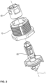
- the present invention describes a connecting element 1 with which two components A, B are connected to each other (see Figures 1 , 12 , 20, 21 ). Within the connection produced, the connecting element 1 maintains a defined distance between the two components A, B. In addition, due to its design, the connecting element 1 is able to compensate for existing tolerances in the alignment of the components A, B to be connected to one another in order to improve the quality, reliability and load-bearing capacity of the connection produced.
- the connecting element 1, 101; 201; 301 enables axial tolerance compensation in the direction of a longitudinal axis L of the hollow screw 10; 110; 210; 310 and lateral tolerance compensation transverse to the longitudinal axis L of the hollow screw 10; 110; 210; 310.
- a first preferred embodiment of the connecting element 1 is shown in a perspective sectional view in Figure 1 It consists of a sleeve-like hollow screw 10 with an external thread 12 and an internal cavity 14.
- the hollow screw 10 is screwed into an opening O of the first component A.
- the thread 12 is configured as a self-tapping and/or self-forming thread. It is also preferred to use other thread configurations that realize a suitable fastening in the opening O of the first component A.
- the self-tapping and/or self-tapping thread creates an anti-rotation effect which holds the hollow screw 10 in the opening O. Even if the hollow screw 10 is adjusted in its axial position by further turning after installation, the self-tapping and/or self-tapping thread continues to ensure a reliable hold of the hollow screw 10 in the opening O of the first component A.
- the banjo bolt 10 has a first opening 18 at a first axial end 16 which is large enough to insert a nut member 40 into the cavity 14 of the banjo bolt 10.
- the nut member 40 which is described in more detail below, is preferably received in the cavity 14 in an approximately coaxial orientation to the longitudinal axis L of the banjo bolt 10.
- a second opening 22 is provided at a second axial end 20 of the hollow screw 10.
- the second opening 22 is smaller in diameter than the first opening 18.
- the second opening 22 is reduced in size by a radial collar 26 that projects radially inwards and on which the nut element 40 is supported by a connecting bolt 60 (see below).
- the hollow screw 10 is in the Figures 3 and 4 shown in more detail in perspective.
- an external drive means 24 in particular a polygon or hexagon, is provided adjacent or next to the second opening 22 of the hollow screw 10.
- the drive means 24 serves to transmit a torque to the hollow screw 10 in order to screw it into the opening O of the first component A and thus fasten it.
- the radial collar 26 preferably has a contact surface 28 for the connecting bolt 60 on an axial outer side.
- the contact surface 28 is preferably designed in a ring shape. It is also preferred to arrange this contact surface 28 in a square shape or consisting of several surface segments in a regular arrangement around the second opening 22 of the hollow screw 10.
- the contact surface 28 also preferably forms a contact surface with the connecting bolt 60, if it is supported or clamped by means of a connecting flange 62 in a force-locking connection with the nut element 40 on the radial collar 26 via the contact surface 28.
- a circumferential embossed rib 30 is preferably provided adjacent to the opening 22 at the first axial end 16.
- the embossed rib 30 also preferably projects beyond the contact surface 28 in the axial direction. It has a round or square circumferential shape.
- the axially protruding embossed rib 30 is preferably pressed or stamped into a connecting flange 62 of the connecting bolt 60 in the force-locking connection between the nut element 40 and the connecting bolt 60.
- this forms a positive connection between the hollow screw 10 and the connecting flange 62 of the connecting bolt 60.
- the positive connection serves to support and ensure the radial position of the nut element 40 and the connecting bolt 60 in relation to the hollow screw 10.
- the positive connection preferably seals the connecting element 1 against media penetrating from the outside, for example by forming a labyrinth seal.
- the hollow screw 10 has a second drive means 32 adjacent to the first axial end 16.
- the drive means 32 is provided according to different preferred embodiments on the axial end face of the first axial end 16 or on the radial outside of the hollow screw 10 or on the radial inside of the cavity 14. Due to its arrangement, the drive means 32 enables accessibility for a tool even when the connecting element 1 is installed and connecting two components. With the aid of a preferred positive connection between the tool and the drive means 32, a torque can be transmitted to the hollow screw 10 in order to change an axial position of the hollow screw 10 in the opening O of the first component A.
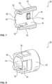
- the connecting bolt 60 is according to a first preferred embodiment of the present invention in the Figures 5 and 6 shown in more detail.
- the connecting bolt 60 is adapted to cooperate with the preferred embodiment of the nut element 40 according to the Figures 7 and 8 preferably to form a detachable connection.
- the preferred connecting bolt 60 has a first axial connecting end 64 in order to establish a positive and/or non-positive connection with the nut element 40.
- the cooperating connecting surfaces of the nut element 40 and the first connecting end 64 of the connecting bolt 60 are designed such that the connection between the connecting bolt 60 and the nut element 40 can be released without causing any damage.
- the connecting surfaces of the first connecting end 64 of the connecting bolt 60 are arranged along a shaft 66 of the connecting bolt 60.
- the shaft 66 is arranged in the cavity 14 of the hollow screw 10 and passes through the nut element 40, which is also arranged there.
- the first connection end 64 is preferably limited in the axial direction by the radially extending connection flange 62, which is arranged outside the cavity 14 of the hollow screw 10.
- the first connection end 64 also runs into a drive means 68 in order to rotate the connection bolt 60 via it.
- the drive means 68 is preferably designed as a polygon, a slot, a web, a cross or an Allen key.
- a second axial connection end 70 Adjacent to the connecting flange 62, a second axial connection end 70 is provided on the side of the connecting bolt 60 facing away from the shaft.
- the second axial connection end 70 is adapted to establish a connection, preferably a detachable connection, with the second component B.
- the second connection end 70 it forms a quick-release fastener with an opening O in the second component B.
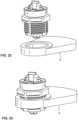
- a bayonet connection is preferred, so that the second connection end 70 can be inserted into a keyhole S (see Figure 24 ) and locks there by a quarter turn.
- the second connection end 70 is also preferred to design the second connection end 70 as a threaded bolt or threaded shaft in order to fasten it in the opening O of the second component B by means of a nut.
- the second connection end 70 has in the Figure 6 shown preferred embodiment a central centering projection 72 with oppositely arranged and radially projecting Locking wings 74.
- the centering projection 72 comprises two centering planes 73 arranged opposite one another and tapering radially inwardly towards the free end of the centering projection 72. These centering planes 73 support the second connection end 70 running into the opening O of the second component B.
- an orientation web 76 is arranged on the centering projection 72, which indicates the angle of rotation setting of the connecting bolt 60 in relation to the keyhole S.
- a similar marking is preferably also found on the axial end of the first connecting end 64.
- the centering projection 72 is inserted through a central opening and the radially projecting locking wings 74 are inserted through radial recesses of the keyhole S (see Figure 25 ).
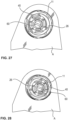
- the connecting bolt 60 is then rotated about its longitudinal axis L, preferably via the drive feature 68, until, after a rotation of preferably 90°, at least one locking bar 78, preferably two locking bars arranged opposite one another, engage in the radial recesses of the keyhole S (see Figure 26 ).
- the locking bar 78 is provided on one side with a release ramp 79.
- the locking bar 78 preferably runs along a partial circular arc around the longitudinal axis L of the connecting bolt 60. Accordingly, the release ramp 79 is attached to a (see Figure 6 ) or at both ends of the locking web 78.
- the connecting bolt 60 is rotated such that the release ramp 79 meets a radial edge of a radial recess of the keyhole S. Due to the rotation, the release ramp 79 presses the locking web 78 in the axial direction out of the radial recess, whereby it is released and enables further rotation of the connecting bolt 60.
- the connecting bolt 60 passes through the second opening 22 of the hollow screw 10 and is held in the cavity 14 by the nut element 40.
- the connecting bolt 60 is according to the Figures 5 and 6 detachably connected to the nut element 40, which is in the Figures 7 and 8 according to preferred embodiments.
- the nut element 40 is constructed in a sleeve-like manner with a circumferential wall 42, an interior space 44 enclosed by the wall 42, an inlet opening 46 and an outlet opening 48.
- the circumferential wall 42 has at least two recesses in order to form an intermediate locking arm 50 extending in the axial direction. More preferably, the nut element 40 has two radially inwardly engaging locking arms 50 which are arranged opposite one another.
- the locking arms 50 have a locking projection 52 that projects radially inwards.
- the locking arm 50 with locking projection 52 preferably creates a releasable snap or locking connection with the connecting bolt 60 as soon as the connecting bolt 60 is axially inserted into the nut element 40 arranged in the cavity 14 of the hollow screw 10.
- This preferably pre-fixing connection between the nut element 40 and the connecting bolt 60 ensures a positioning movement of the connected parts in the radial direction within the cavity 14 of the hollow screw 10.
- the outer limit of the radial mobility is determined by the inner diameter of the second opening 22 of the hollow screw 10.
- the locking projection 52 preferably snaps into a recess 80 for pre-positioning the connecting bolt 60 on the nut element 40.
- the locking projection 52 slides on a positioning ramp 82 into or towards the recess 80.
- a guide cam 54 of the nut element 40 preferably engages in a guide groove 84 on the shaft 66, which preferably runs in the axial direction of the connecting bolt 60.
- the inclusion of the guide cam 54 in the guide groove 84 brings about a preferred relative axial guidance between the nut element 40 and connecting bolt 60.
- the nut element 40 and connecting bolt 60 are protected against twisting against each other.
- the positive connection between the guide cam 54 and the guide groove 84 as well as between the locking projection 52 and the recess 80 individually or together as an anti-twisting device between the nut element 40 and the connecting bolt 60.
- the hollow screw 10 is screwed into the opening O in component A. This is preferably done as a pre-positioning step of the connecting element 1 or as the first step in a connection process of the two components A and B.
- the nut element 40 is already pre-assembled with the connecting bolt 60 in the cavity 14 of the hollow screw 10, i.e. not yet firmly connected. This means that the connecting bolt 60 and the nut element 40 are pre-fixed to one another via at least one locking connection (see above). This pre-fixing ensures radial and partially axial mobility of the connecting bolt 60 in the cavity 14.
- the second connection end 70 is then preferably fastened in the opening O of the second component B.
- the second axial connection end 70 and the opening O in the second component B form a quick-lock or a bayonet connection (see below).
- connection of the hollow screw 10 to the first component A and the connecting bolt 60 to the second component B preferably results in the required radial position of the connecting bolt 60 within the second opening 22 of the hollow screw 10. Accordingly, a radial tolerance compensation was carried out, supported by the preferably loose connection between the nut element 40 and the connecting bolt 60. This led to an adjustment of the radial position of the connecting bolt 60 in the connecting element 1 to the alignment of the components A and B to one another.
- the radial position of the connecting bolt 60 is preferably fixed in the hollow screw 10.
- a tool also preferably transmits a torque to the nut element 40 via a drive feature 56 in the circumferential wall 42 of the nut element 40, preferably a recess on the radial outside of the nut element 40.
- the resulting rotation of the nut element 40 on the shaft 66 of the connecting bolt 60 results in the guide cam 54 being guided via an insertion bevel 86 into a fastening position 88 in the shaft 66 of the connecting bolt 60.
- the guide cam 54 is guided via the insertion bevel 86 into the fastening position 88 on the connecting bolt 60.
- the movement of the guide cam 54 leads to the connecting bolt 60 being displaced in the axial direction towards or into the nut element 40, while the nut element 40 is supported on the radial collar 26 in the cavity 14.
- the connecting bolt 60 is clamped via its connecting flange 62 on the radial collar 26 of the hollow screw 10 or are fixed in a certain radial position in relation to the central longitudinal axis L of the hollow screw 10 by friction.
- a sealing element 90 is provided on the connecting flange 62 of the connecting bolt 60.
- the sealing element 90 has a hat-like or pot-like shape with a base 92 and a circumferentially projecting wall 94.
- the opening of the sealing element 90, which results from the shape features, is preferably oriented in the direction of the second connecting end 70 of the connecting bolt 60.
- the sealing element 90 preferably consists of an elastic material, it seals against the component B when a connection is made, as shown in the Figures 10 and 17 is shown.
- the base surface 92 is designed as a circular ring, the diameter of the inner opening of which is determined by the diameter of the shaft 66 of the connecting bolt 60.
- the size of this base surface 92 has the advantage that the sealing element 90 is held between the connecting flange 62 and the adjacent contact surface 28 of the hollow screw 10 in a frictional or force-fitting manner. This leads to a sealing of the connecting element 1 to the outside.
- the hollow screw 10 has the embossed rib 30.
- the ring-shaped, circumferential embossed rib 30 preferably protrudes beyond the contact surface 28 at the second axial end 20.
- the embossed rib 30 deforms the sealing element 90 and thereby preferably forms a type of labyrinth seal.
- the circular ring of the base surface 192 is reduced to a retaining collar that projects radially inwards.
- a side of the connecting flange 62 facing the shaft is available for the frictional connection on the radial collar 26.
- the connecting flange 62 preferably has radial ribs 63 that are embossed into the contact surface 28 and/or the embossed rib 30 in the frictional connection with the nut element 40. In this way, additional positive connections are formed that support the function of the connecting element 1.
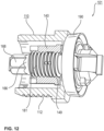
- FIG. 12 A further preferred embodiment of the connecting element 101 is shown in perspective in the Figures 12 and 16 shown.
- Figure 13 shows only three components of the connecting element 101 in a perspective exploded view, while in the Figures 14 and 15 the connecting bolt 160 and the nut element 140 are shown individually.
- connection element 1 As in Figure 1
- the further preferred embodiment of the connecting element 1 shown as an example consists of Figure 12 from only three components.
- the connecting bolt 60; 160 with sealing element 90; 190 is considered to be one component.
- the use of only three components to provide the connecting element 1; 101 results in low manufacturing costs in terms of production, material costs and assembly.
- the installation costs are preferably reduced because the connection is limited to the hollow screw 10; 110 and the second connection end 70; 170 of the connecting bolt 60; 160. This part limitation and the associated advantages apply to all connecting elements 1; 101; 201; 301 described here.
- the shaft 166 of the connecting bolt 160 has an external thread 181 and the nut element 140 has a matching internal thread 149. Accordingly, the nut element 140 and the connecting bolt 160 are connected to one another in a rotational manner.
- the rotation is applied in a known manner via the drive feature 156 on the nut member 140 and/or via the drive feature 168 on the connecting bolt 160.
- the external thread 181 of the connecting bolt 160 has at least one locking rib 183 for thread locking.
- the nut element 140 is screwed onto the external thread 181 of the shaft 166.
- the nut element 140 is only screwed on so far that the internal thread 149 does not yet reach the locking rib 183.
- the nut element 140 can still be positioned axially and together with the connecting bolt 160 radially in the hollow screw 110.
- the nut element 140 is screwed completely onto the external thread 181.
- the connecting flange 162 and the nut element 140 clamp the radial collar 126 between them in a frictional or force-locking manner, as shown in Figure 17
- the selected radial position of the connecting bolt 160 is fixed, as shown in the Figures 27, 28
- the locking rib 183 also preferably prevents the threaded connection between the nut element 140 and the connecting bolt 160 from loosening if no minimum torque is applied to overcome the thread lock.
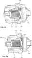
- the Figures 16 and 17 the installation process of the connecting element 101 already described above. After the connection consisting of the nut element 140 and the connecting bolt 160 has been pre-positioned in the hollow screw 110, the hollow screw 110 is screwed into the opening O of the first component A.
- the movable connection consisting of nut element 140 and connecting bolt 160 is preferably positioned radially so that the second axial connecting end 170 of the connecting bolt 116 is aligned with the preferred keyhole S of the second component B.
- the connecting bolt 160 By preferentially rotating the connecting bolt 160 via the drive feature 168, the second connecting end 170 is secured in the keyhole S.
- a torque is transmitted to the nut element 140 via a suitable form-fit connection with the drive feature 156 on the nut element 140.
- Turning the nut element 140 screws the internal thread 149 further onto the external thread 166 of the connecting bolt 160.
- the screwing ends with an effective frictional connection or clamping of the connecting flange 162 and the nut element 140 on the circumferential radial collar 126 of the hollow screw 110.
- the radial ribs 163 of the connecting flange 162 are also preferably pressed into the embossed rib 130 in order to achieve additional form-fit connection.
- the sealing element 190 already seals against the second component B when the second connection end 170 is connected to the second component B.
- the nut element 140 is equipped with an axially protruding compression limiter 158.
- the compression limiter 158 protrudes in an annular shape in the direction of the connecting flange 162 from the nut element 140.
- the compression limiter 158 is, according to various preferred embodiments, available as a single part (see Figure 18 ) or integrated into the nut element 140 (see Figure 19 ).
- the connecting flange 162 is preferably screwed onto the block with the compression limiter 158.
- This block screw connection limits the strength of the clamping of the radial collar 126 of the hollow screw 110 between the nut element 140 and the connecting flange 162.
- a further preferred embodiment of the connecting element 201 shows Figure 20 .
- the nut element 240 is not detachably attached to the shaft 266 of the connecting bolt 260.
- the nut element 240 is constructed similarly to a snap ring. Accordingly, an inner diameter of the nut element 240 is smaller than an outer diameter of the shaft 266 of the connecting bolt 260.
- the nut element 240 has an axially continuous gap 243 in the wall 242. This allows the approximately ring-shaped wall 242 to be expanded in diameter, to clamp the nut element 240 onto the shaft 266.
- the frictional connection achieved in this way between the shaft 266 and the nut element 240 ensures the likewise frictional or force-fitting connection between the connecting flange 262 and the nut element 240 on the radial collar 226 of the hollow screw 210.
- the hollow screw 210 is first screwed into the component A (step S1).
- the nut element 240 and the connecting bolt 260 are loosely connected to each other in the cavity 214 of the hollow screw 210.
- step S2 By rotating the connecting bolt 260 via the drive means 268, the second connecting end 270 is fastened in the second component B (step S2).
- the appropriate radial position of the connecting bolt 260 could be set in alignment with the connected components A, B.
- the nut element 240 is displaced as far as possible in the direction of the connecting flange 262 using a suitable tool on the shaft 266 based on its clamping ring-like configuration. Due to the clamping configuration, the nut element 242 maintains the frictional connection with the connecting bolt 260 in the radial position on the radial collar 226 and thereby also preferably fixes the radial position of the nut element 240 and connecting bolt 260 in the cavity 214.
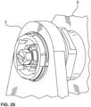
- FIG. 21 A further preferred embodiment of the connecting element 301 is shown in Figure 21 shown.
- the nut element 340 is designed as a non-detachable locking ring structure. Accordingly, the nut element 340 has a circumferential ring 341 with a plurality of locking webs 345 extending therefrom in the axial direction. The locking webs 345 run in the direction of the drive feature 368 and are supported on a locking projection 367 running around the shaft 366.
- the installation of the connecting element 301 is carried out analogously to the installation of the connecting element 201 described above.
- connection method of the first A and the second component B at a defined distance from one another which has already been described above for the various preferred embodiments of the connecting element 1; 101; 201; 301, can be summarized in the following steps.
- a first step S1 the hollow screw 10; 110; 210; 310 of the connecting element 1; 101; 201; 301 is screwed into the first fastening opening O on the first component A.
- the second connection end 70; 170; 270; 370 of the connecting bolt 60; 160; 260; 360 is then fastened in a second fastening opening S of the second component B, whereby radial tolerances in an axial alignment of the hollow screw 10; 110; 210; 310 and the connecting bolt 60; 160; 260; 360 are compensated.
- the nut element 40; 140; 240; 340 and the first connecting end 64; 164; 264; 364 of the connecting bolt 60; 160; 260; 360 are firmly connected to one another so that the connecting bolt 60; 160; 260; 360 is fastened to the hollow screw 10; 110; 210; 310.
- the hollow screw 10; 110; 210; 310 is rotated in the first component A in order to adjust an axial position of the connecting element 1; 101; 201; 301.
- the nut element 40; 140; 240; 340 is loosened within the hollow screw 10; 110; 210; 310, then a radial position of the connecting bolt 60; 160; 260; 360 is changed in comparison to the hollow screw 10; 110; 210; 310 and then the nut element 40; 140; 240; 340 is refastened to the connecting bolt 60; 160; 260; 360.
Landscapes
- Engineering & Computer Science (AREA)
- General Engineering & Computer Science (AREA)
- Mechanical Engineering (AREA)
- Chemical & Material Sciences (AREA)
- Combustion & Propulsion (AREA)
- Transportation (AREA)
- Mutual Connection Of Rods And Tubes (AREA)
Abstract
Description
- Die vorliegende Erfindung betrifft ein Verbindungselement zweier zueinander beabstandeter Bauteile mit Toleranzausgleichsfunktion. Zudem betrifft vorliegende Erfindung ein Verbindungsverfahren eines ersten und eines zweiten Bauteils in einem Abstand zueinander mithilfe des oben genannten Verbindungselements.
- Im Stand der Technik sind verschiedene Verbindungselemente bzw. Verbindungssysteme bekannt, um zwei Bauteile in einem festen Abstand zueinander miteinander zu verbinden. So offenbart beispielsweise
US 2017/0051780 A1 ein erstes Bauteil, in dessen Öffnung ein hülsenförmiger Clips angeordnet wird. Eine Halterung eines zweiten Bauteils befestigt einen Stift, der in seiner Form zur Herstellung einer formschlüssigen Verbindung an den oben genannten Clips angepasst ist. Mit dem Ineinanderstecken von Clips und Stift wird eine Verbindung zwischen diesen beiden Bauteilen hergestellt. Dieses Verbindungssystem hat jedoch den Nachteil, dass lediglich eine axiale Verbindung zwischen dem Stift und dem Clips herstellbar ist, während auftretende Toleranzen in axialer und in seitlicher Richtung nicht durch eine Korrekturmöglichkeit ausgeglichen werden können. -
DE 42 24 575 A1 beschreibt eine Verbindungsanordnung mit selbsttätigem Toleranzausgleich. Zu diesem Zweck wird die Verbindungsanordnung zunächst an einem ersten Bauteil befestigt. Das zweite Bauteil, welches vom ersten Bauteil beabstandet ist, wird mithilfe eines Gewindebolzens über die Verbindungsanordnung mit dem ersten Bauteil verbunden. Während des Einschraubens des Gewindebolzens in die Verbindungsanordnung erfolgt ein selbsttätiger Toleranzausgleich, in dem ein Verstellelement den Abstand zwischen dem ersten und dem zweiten Bauteil ausgleicht. Sobald die Toleranzausgleichsanordnung den Abstand beider Bauteile überbrückt, wird der Gewindebolzen in ein befestigendes Aufnahmegewinde eingeschraubt. Diese Verbindungsanordnung ist aufwändig in ihrer Konstruktion. Denn zunächst muss der selbsttätige Toleranzausgleich durch die Abstimmung verschiedener Gewindeverbindungen innerhalb der Verbindungsanordnung realisiert werden. Zudem erlaubt nicht jede Verbindungssituation den Einsatz eines Gewindebolzens, der nur unter Nutzung einer bestimmten Verarbeitungszeit verlässlich mit der Verbindungsanordnung verschraubt werden kann. -
DE 10 2007 002 699 A1 beschreibt eine Befestigungseinrichtung die auf der Nutzung zweier teleskopartig miteinander verbundener Hülsen aufbaut. Diese Hülsen sind über ein Innen- und ein Außengewinde miteinander verbunden, um einen Abstand zwischen einem ersten und einem zweiten Bauteil überbrücken zu können. Innerhalb der inneren Hülse verläuft ein verbindender Gewindebolzen, um das erste und das zweite Bauteil miteinander zu verschrauben. Entsprechend können die teleskopartig zusammenwirkenden Hülsen axiale Toleranzen ausgleichen. Da der verbindende Gewindebolzen in seinem Querschnitt kleiner ist als der Innendurchmesser der inneren Hülse, ist ein Ausgleich radialer Toleranzen durch einen relativen Versatz zwischen Gewindebolzen und umgebender Hülse gewährleistet. -
US 2018/0328390 A1 nutzt einen zentralen Bolzen mit zwei einander gegenüberliegend angeordneten Gewindeenden und einem dazwischen liegenden Abstandsblock, um zwei Bauteile in einem gewissen Abstand zueinander zu befestigen. Die beiden Gewindeenden erfordern jeweils ein entsprechendes Gegengewinde, um eine Verbindung auf beiden Seiten des Gewindebolzens herstellen zu können. Dies ist mit einem entsprechend konstruktiven wie auch einem späteren Verarbeitungsaufwand verbunden. Um den Verbindungsaufwand an zumindest einem Gewindeende des zentralen Bolzens zu reduzieren, wird eine Verbindungshülse auf das eine Gewindeende des Verbindungsbolzens aufgeschraubt. Diese Verbindungshülse ist in einer mehrteiligen Verriegelungskonstruktion des zweiten Bauteils verriegelbar. Dazu wird in einem Haltekäfig des zweiten Bauteils ein Verriegelungsclip gehalten, in welchem die auf den Gewindebolzen aufgeschraubte Hülse verrastet werden kann. Zum Ausgleich axialer Toleranzen zwischen den beiden Bauteilen lässt sich der Gewindebolzen auch in der verrasteten Gewindehülse verstellen. Zu diesem Zweck ist die Gewindehülse in ihrer verrasteten Anordnung drehbar angeordnet. Aufgrund der Vielzahl an erforderlichen Teilen zum Herstellen der Verbindung zwischen den beiden zueinander beabstandeten Bauteilen wird deutlich, dass diese Verbindungsanordnung neben einem hohen Herstellungsaufwand auch einen entsprechend hohen Installationsaufwand erfordert. - Mit Blick auf den Stand der Technik ist es daher die Aufgabe vorliegender Erfindung, ein alternatives Verbindungselement für zwei zueinander beabstandete Bauteile mit Toleranzausgleichsfunktion bereitzustellen.
- Die obige Aufgabe wird gelöst durch ein Verbindungselement gemäß dem unabhängigen Patentanspruch 1, eine Verbindung von zwei Bauteilen mit dem Verbindungselement gemäß Patentanspruch 12 sowie durch ein Verbindungsverfahren von zwei Bauteilen gemäß Patentanspruch 13. Vorteilhafte Ausführungsformen und Weiterentwicklungen ergeben sich aus der nachfolgenden Beschreibung, den Zeichnungen sowie den anhängenden Patentansprüchen.
- Vorliegende Erfindung offenbart ein Verbindungselement zweier zueinander beabstandeter Bauteile mit Toleranzausgleichsfunktion. Das Verbindungselement weist die folgenden Merkmale auf: eine Hohlschraube mit einem Außengewinde, mit dem eine Gewindeverbindung zu einem ersten Bauteil herstellbar ist, die über mindestens ein Antriebsmittel der Hohlschraube in deren Längsrichtung verstellbar ist, ein Mutternelement, das in einem Aufnahmeraum der Hohlschraube aufgenommen ist und das eine radial innere Funktionsfläche umfasst, sodass mit einem ersten Verbindungsende eines Verbindungsbolzens eine form- und/oder kraftschlüssige Verbindung herstellbar ist, wobei der Verbindungsbolzen ein zweites Verbindungsende aufweist, mit dem eine Verbindung zu einem zweiten Bauteil herstellbar ist.
- Vorliegende Erfindung beschreibt ein Verbindungselement, welches zwei Bauteile in einem festgelegten Abstand zueinander miteinander verbindet. Im Rahmen dieser Verbindung bzw. dieser Befestigung der beiden Bauteile aneinander ermöglicht das Verbindungselement den Ausgleich verschiedener Toleranzen zur Abstimmung auf eine optimale Verbindung. Bei diesen Toleranzen handelt es sich einmal um axiale Toleranzen, die durch Drehen der Hohlschraube einstellbar sind. Denn die Hohlschraube sitzt in einem vorzugsweise selbstgefurchten Gewinde des ersten Bauteils. Durch Drehen der Hohlschraube wird das Verbindungselement in seiner Axialrichtung - also entlang seiner Längsachse - in die eine oder andere Richtung versetzt. Zudem ermöglicht der innere Hohlraum der Hohlschraube sowie die darin angeordnete Kombination von Mutternelement und Verbindungsbolzen den Ausgleich von seitlichen Toleranzen senkrecht zur Längsachse des Verbindungsbolzens. Denn die Kombination aus Verbindungsbolzen und Mutternelement stellt bevorzugt während des Herstellens der Verbindung eine kraftschlüssige Verbindung mit der Hohlschraube her. Die Position der kraftschlüssigen Verbindung lässt sich innerhalb des zur Verfügung stehenden Hohlraums der Hohlschraube verändern, sodass in einer Ebene senkrecht zur Längsachse des Verbindungsbolzens ein Ausgleich von seitlichen Toleranzen durch das Verbindungselement zur Verfügung gestellt wird. Es versteht sich, dass die Bezeichnung kraftschlüssig und reibschlüssig synonym verwendet werden.
- Der Verbindungsbolzen verfügt über ein erstes funktionales Verbindungsende, welches mit dem Mutternelement eine form- und/oder kraftschlüssige Verbindung eingeht. In Abhängigkeit von den zu erzielenden Verbindungskräften innerhalb des Verbindungselements sowie der zur Verfügung stehenden Taktzeit zum Herstellen der Verbindung kann die Verbindung aus Mutternelement und Verbindungsbolzen als Schnellverbinder oder Rastverbinder oder als Gewindeverbindung realisiert sein.
- Entsprechend weisen das Mutternelement als Funktionsfläche ein Innengewinde und der Verbindungsbolzen ein Außengewinde oder das Mutternelement einen radial einwärts gerichteten Führungssteg oder Nocken und der Verbindungsbolzen eine krumm- oder geradlinig verlaufende
- Führungsnut oder eine Rampe auf. Weiter bevorzugt sind auf dem Mutternelement und dem Verbindungsbolzen ineinandergreifende Raststege und Rastnuten vorgesehen, die an aufeinanderfolgenden axialen Positionen einander zugeordnet positioniert sind.
- Im Hinblick auf das zweite Verbindungsende des Verbindungsbolzens ist es ebenfalls bevorzugt, eine kraft- und/oder formschlüssige Verbindung mit dem zweiten Bauteil herzustellen. Vorzugsweise stellt zu diesem Zweck das zweite Bauteil eine Öffnung bereit, in welche das zweite Verbindungsende des Verbindungsbolzens eingreift und sich dort befestigt. Gemäß einer bevorzugten Ausgestaltung vorliegender Erfindung ist das zweite Verbindungsende als Schnellverbinder ausgestaltet, wie beispielsweise ein Bajonettverschluss. Dieser greift in ein passendes Schlüsselloch im zweiten Bauteil ein. Gemäß einer weiteren bevorzugten Ausgestaltung weist das zweite Verbindungsende des Verbindungsbolzens einen Gewindeabschnitt auf, der mit einem passenden Mutternelement eine Verbindung herstellt.
- Gemäß einer bevorzugten Ausführungsform vorliegender Erfindung hat eine erste Öffnung der Hohlschraube einen Öffnungsdurchmesser, der größer ist als ein Bolzendurchmesser des in die Hohlschraube ragenden Verbindungsbolzens, sodass der Verbindungsbolzen innerhalb der ersten Öffnung der Hohlschraube zum Ausgleich von Toleranzen seitlich zu seiner Längsachse versetzbar ist.
- Wie oben bereits angesprochen worden ist, ermöglicht die Konstruktion der hohlzylinderartig oder hülsenförmig aufgebauten Hohlschraube einen seitlichen Versatz des Verbindungsbolzens in Bezug auf dessen Längsachse innerhalb der Hohlschraube. Auf diese Weise werden seitliche oder radiale Toleranzen im Hinblick auf die Längsachse des Verbindungsbolzens sowie die Längsachse der Hohlschraube ausgleichbar. Da vorzugsweise der Verbindungsbolzen in Kombination mit dem Mutternelement an einer bestimmten Radialposition innerhalb der Hohlschraube befestigt wird, werden auf diese Weise die für die Verbindung erforderlichen Toleranzen in der Ausrichtung von Hohlschraube und Verbindungsbolzen ausgleichbar, um eine optimale Verbindungsqualität zu erzielen.
- Gemäß einer weiteren bevorzugten Ausgestaltung vorliegender Erfindung weist die Hohlschraube an der ersten Öffnung einen in die erste Öffnung ragenden Radialkragen auf, an dem das Mutternelement und der Verbindungsbolzen durch eine gemeinsame Verbindung befestigbar sind, um eine Radialposition des Verbindungsbolzens innerhalb der ersten Öffnung zu fixieren.
- Gemäß einer bevorzugten Ausgestaltung vorliegender Erfindung weist das erste Bauteil eine Aufnahmeöffnung zum Einschrauben der Hohlschraube auf. Das zweite Bauteil ist ebenfalls mit einer Aufnahmeöffnung oder einer anderen passenden Konstruktion zur Herstellung einer Verbindung mit dem zweiten Ende des Verbindungsbolzens ausgestattet. Um diese beiden Öffnungen bzw. das erste und das zweite Bauteil effektiv zu verbinden, werden Ausrichtungstoleranzen zwischen dem ersten und dem zweiten Bauteil nicht durch Bewegung der Bauteile sondern durch Bewegung bzw. Versatz des Verbindungsbolzens innerhalb der Hohlschraube ausgeglichen. Gemäß einer bevorzugten Ausgestaltung vorliegender Erfindung wird der Verbindungsbolzen nach Einnahme seiner geeigneten Radialposition innerhalb der Hohlschraube fest mit dem Muttemelement verbunden. Dies erzielt ein bevorzugtes Klemmen bzw. allgemein eine kraftschlüssige Verbindung von Mutternelement und Verbindungsbolzen mit einem radial einwärts in die Hohlschraube ragenden Radialkragen der Hohlschraube. Auf diese Weise ist die Verbindung aus Mutternelement und Funktionsbolzen fest innerhalb der Hohlschraube angeordnet. Die Konstruktion des bevorzugten Radialkragens eröffnet die Möglichkeit, dass der Verbindungsbolzen nicht zwingend koaxial zu einer Längsachse der Hohlschraube angeordnet sein muss. Vielmehr ergibt sich bevorzugt aus der Nutzung des Radialkragens und einer kraftschlüssigen Verbindung zwischen Verbindungsbolzen und Mutternelement an diesem Radialkragen eine parallele Ausrichtung des Verbindungsbolzens zu der Längsachse der Hohlschraube, sodass diese bevorzugt nebeneinander in einer gemeinsamen gedachten Ebene liegen.
- Vorzugsweise hat der Verbindungsbolzen zwischen dem ersten und dem zweiten Verbindungsende einen radial auswärts ragenden Verbindungsflansch, der eine kraftschlüssige Verbindung mit der Hohlschraube unterstützt.
- Gemäß einer bevorzugten Ausgestaltung vorliegender Erfindung ist an einem Verbindungsbolzen ein radial auswärts ragender Verbindungsflansch angeordnet. Eine bevorzugte feste Verbindung zwischen Verbindungsbolzen und Mutternelement führt dazu, dass der Radialkragen der Hohlschraube zwischen dem Verbindungsflansch und dem Mutternelement kraftschlüssig gehalten wird. Dies gewährleistet eine Fixierung der gewählten Radialposition des Verbindungsbolzens innerhalb der Hohlschraube.
- Der Verbindungsflansch weist erfindungsgemäß bevorzugt der Hohlschraube zugewandte Stege oder Rippen auf, die eine Verbindung zwischen Hohlschraube und Verbindungsbolzen formschlüssig unterstützen.
- Gemäß einer weiteren bevorzugten Ausgestaltung vorliegender Erfindung sind an dem Verbindungsflansch an einer der Hohlschraube zugewandten Seite radial verlaufende Stege vorgesehen. Diese Stege stehen aus der Ebene des Verbindungsflansches hervor. Dies führt dazu, dass im Rahmen einer bevorzugten kraftschlüssigen Verbindung mit dem Mutternelement die aus dem Verbindungsflansch hervorstehenden Stege in vorzugsweise den Radialkragen der Hohlschraube oder in einen weiteren Teil der Hohlschraube an ihrem axialen Ende eingedrückt werden. Eine sich daraus bevorzugt ergebene formschlüssige Verbindung bildet gemäß unterschiedlicher bevorzugter Ausgestaltungen eine Labyrinthdichtung oder eine Drehhemmung des Verbindungsbolzens relativ zur Hohlschraube. Diese beiden funktionellen alternativen Ausgestaltung des Verbindungsflansches unterstützen eine verbesserte Qualität der Verbindung zwischen dem ersten und dem zweiten Bauteil über das erfindungsgemäß bevorzugte Verbindungselement.
- In einer weiter bevorzugten Ausgestaltung vorliegender Erfindung ist an dem Verbindungsflansch ein hutartiges Dichtungselement vorgesehen, welches in Richtung des zweiten Verbindungsendes vorsteht, um eine Verbindung zu einem zweiten Bauteil abzudichten.
- Gemäß einer weiteren bevorzugten Ausgestaltung vorliegender Erfindung ist an dem Verbindungsflansch ein Dichtungselement vorgesehen. Dieses Dichtungselement ist in Richtung des zweiten Bauteils derart orientiert, dass bei Verbindung des zweiten Verbindungsendes des Verbindungsbolzens mit dem zweiten Bauteil ein abdichtender Kontakt zwischen dem Dichtungselement und dem zweiten Bauteil hergestellt wird. Dieser Kontakt sorgt dafür, dass vorzugsweise das Dichtungselement um eine Befestigungsöffnung am zweiten Bauteil, in welche der Verbindungsbolzen eingreift, die Verbindung zum Verbindungselement umlaufend abgedichtet wird. Dies gewährleistet vorzugsweise, dass Feuchtigkeit oder Staub oder ähnliche Verschmutzung durch die Öffnung im zweiten Bauteil nicht bis zu dem verbindenden Verbindungselement durchdringen kann. Denn das Dichtungselement schirmt die Öffnung im zweiten Bauteil derart ab, dass sich derartige Verschmutzungen am Dichtungselement sammeln.
- Zur Realisierung seiner abdichtenden Funktion ist das Dichtungselement gemäß einer bevorzugten Ausgestaltung hutartig oder topfartig mit einer Öffnung in Richtung des zweiten Bauteils oder anders gesagt abgewandt von der Hohlschraube ausgestattet. Auf diese Weise öffnet sich das Dichtungselement in Richtung des zweiten Verbindungsendes des Verbindungsbolzens. Die bevorzugte hut- oder topfartige Struktur des Dichtungselements hat zur Folge, dass ähnlich einer Hutkrempe oder einer umlaufenden Topfwand eine Wand des Dichtungselements von der Hohlschraube weg, also in Richtung des zweiten Verbindungsendes des Verbindungsbolzens, orientiert ist. Da für das Dichtungselement gemäß einer bevorzugten Ausgestaltung ein flexibles Material verwendet wird, wie beispielsweise ein Elastomer, legt sich dieser Rand beim Verbinden an das zweite Bauteil an, um auf diese Weise die Dichtfunktion zu realisieren.
- Ebenfalls bevorzugt hat der Verbindungsbolzen angrenzend an das erste Verbindungsende ein Antriebsmittel.
- Um eine bevorzugte Verbindung zwischen dem zweiten Verbindungsende des Verbindungsbolzens und dem zweiten Bauteil herstellen zu können, ist ein Antriebsmittel zur Übertragung eines bevorzugten Drehmoments auf den Verbindungsbolzen erforderlich. Gemäß einer bevorzugten Ausgestaltung vorliegender Erfindung ist dieses Antriebsmittel benachbart zum ersten Verbindungsende des Verbindungsbolzens angeordnet. Dies hat den Vorteil, dass das zweite Verbindungsende des Verbindungsbolzens, welches von der Hohlschraube abgewandt ist, funktionell vollständig zum Herstellen der Verbindung mit dem zweiten Bauteil zur Verfügung steht.
- Des Weiteren ermöglicht das Verbindungselement basierend auf dieser Konstruktion, dass die Verbindung zwischen dem ersten und dem zweiten Bauteil auch allein mit auf einer einseitigen Zugänglichkeit der Verbindungsstelle herstellbar ist. Somit ist das vorliegende Verbindungselement gerade auch an schwer zugänglichen Verbindungsstellen von zwei Bauteilen unter Gewährleistung des geforderten Abstands zwischen den beiden Bauteilen einsetzbar.
- Gemäß einer weiteren bevorzugten Ausführungsform vorliegender Erfindung bilden die radial innere Funktionsfläche des Mutternelements und das erste Verbindungsende des Verbindungsbolzens einen Schnellverschluss, insbesondere einen Vierteldreh-Schnellverschluss.
- Um eine erforderliche Taktzeit zum Herstellen der Verbindung zwischen den beiden Bauteilen möglichst gering zu halten, ist zwischen dem Mutternelement und dem ersten Verbindungsende des Verbindungsbolzens eine Schnellverschlussverbindung vorgesehen. Diese realisiert mit geringem Arbeitsaufwand eine kraftschlüssige und/oder formschlüssige Verbindung zur Hohlschraube, um auftretende Toleranzen beim Verbinden der beiden Bauteile nachfolgend mit dem Verbindungselement ausgleichen zu können.
- Gemäß einer weiteren bevorzugten Ausgestaltung vorliegender Erfindung weist das erste Verbindungsende des Verbindungsbolzens ein Außengewinde und das Mutternelement ein dazu passendes Innengewinde zum Herstellen einer Gewindeverbindung auf.
- Gemäß einer weiteren bevorzugten Ausgestaltung vorliegender Erfindung ist die Verbindung zwischen dem Mutternelement und dem ersten Verbindungsende des Verbindungsbolzens als eine Gewindeverbindung vorgesehen. Dies bedeutet, dass das Mutternelement ein Innengewinde aufweist und das erste Verbindungsende des Verbindungsbolzens ein dazu passendes Außengewinde. Eine derartige Gewindeverbindung realisiert in einem beispielgebenden Vergleich zu einer Schnellverschluss-Verbindung höhere Verbindungskräfte, die in Abhängigkeit von den beiden miteinander zu verbinden Bauteilen erforderlich sein könnten. Im Vergleich zu einem verbindenden Schnellverschluss zwischen dem Mutternelement und dem ersten Verbindungsende erfordert eine Gewindeverbindung mehr Zeit beim Herstellen der Verbindung als eine Rastverbindung oder eine Bajonettverbindung.
- Vorzugsweise bildet das zweite Verbindungsende des Verbindungsbolzens einen Schnellverschluss mit einer Verbindungsöffnung in einem zweiten Bauteil, insbesondere einen Vierteldrehung-Schnellverschluss oder einen Bajonettverschluss.
- Gemäß einer weiteren bevorzugten Ausgestaltung vorliegender Erfindung ist das zweite Verbindungsende des Verbindungsbolzens als Schnellverschluss ausgestaltet. Entsprechend wirkt diese Funktion der Ausgestaltung des zweiten Verbindungsendes des Verbindungsbolzens derart mit einer Öffnung im zweiten Bauteil zusammen, dass beispielsweise nur mit einer Vierteldrehung eine belastbare kraft- und/oder formschlüssige Verbindung mit dem zweiten Bauteil herstellbar ist. Mithilfe dieser funktionellen Ausgestaltung lässt sich die Taktzeit zum Herstellen der Verbindung zwischen den beiden Bauteilen weiter reduzieren. Natürlich ist es ebenfalls bevorzugt, diese Verbindung zugunsten höherer Verbindungskräfte derart anzupassen, dass beispielsweise eine Gewindeverbindung zwischen dem zweiten Verbindungsende des Verbindungsbolzens und dem zweiten Bauteil an der Bauteilöffnung hergestellt wird. Entsprechend weist beispielsweise das zweite Bauteil ein Innengewinde an der Bauteilöffnung auf oder eine Schweißmutter angrenzend an die Bauteilöffnung oder aber eine Blindnietmutter, die zuvor in die Bauteilöffnung des zweiten Bauteils gesetzt worden ist.
- Gemäß einer anderen bevorzugten Ausführungsform vorliegender Erfindung weist die Hohlschraube ein erstes und ein zweites Antriebsmittel auf, die benachbart zu den gegenüberliegenden axialen Enden angeordnet sind, insbesondere ein äußeres Antriebsmittel und ein inneres Antriebsmittel.
- Die Hohlschraube wird in eine Öffnung des ersten Bauteils eingeschraubt. Diese Vorpositionierung der Hohlschraube bzw. des Verbindungselements lässt sich beispielsweise in einem Vorbereitungsverfahren des ersten Bauteils realisieren. Entsprechend sind diese Vorbereitungsverfahren häufig nicht durch mangelnden Platzbedarf gekennzeichnet, sodass vorzugsweise die Hohlschraube über ein äußeres Antriebsmerkmal in die entsprechende Öffnung des ersten Bauteils eingeschraubt wird. Eine bekannte Ausgestaltung eines äußeren Antriebsmittels ist ein Mehrkant, wie beispielsweise eine Sechskant-Struktur.
- Um im Rahmen einer hergestellten Verbindung zwischen den beiden Bauteilen einen bevorzugten axialen Toleranzausgleich zwischen dem ersten und dem zweiten Bauteil gewährleisten zu können, weist die Hohlschraube vorzugsweise ein zweites Antriebsmerkmal auf. Dieses zweite Antriebsmerkmal kommt dann zum Tragen, wenn beispielsweise das äußere erste Antriebsmerkmal, der oben genannte Mehrkant, schwer zugänglich oder durch die hergestellte Verbindung verdeckt sein sollte. Daher ist es erfindungsgemäß bevorzugte, innerhalb der Hohlschraube ein Antriebsmerkmal vorzusehen, in welches mit einem passenden Werkzeug formschlüssig eingegriffen werden kann. Gemäß einer bevorzugten Ausgestaltung vorliegender Erfindung ist das zweite Antriebsmerkmal an dem axialen Ende der Hohlschraube vorgesehen, welches von dem Radialkragen abgewandt ist. Somit unterstützt auch dieses zweite Antriebsmerkmal bevorzugt die oben bereits angesprochene einseitige Zugänglichkeit beim Herstellen einer Verbindung zwischen einem ersten und einem zweiten Bauteil.
- Vorliegende Erfindung offenbart zudem eine Verbindung eines ersten und eines zweiten zueinander beabstandeten Bauteils mit Hilfe des oben beschriebenen Verbindungselements.
- Mithilfe des erfindungsgemäß bevorzugten Verbindungselements wird vorzugsweise eine Fahrzeugleuchte mit einem Fahrzeugchassis oder eine Griffkonstruktion mit der Fahrzeugkarosserie oder eine Sitzkonstruktion mit einem Fahrzeugrahmen oder Ähnliches verbunden. Grundsätzlich werden zwei Bauteile miteinander verbunden, die in einem bestimmten Abstand zueinander angeordnet und befestigt sein müssen.
- Zudem beschreibt vorliegende Erfindung ein Verbindungsverfahren eines ersten und eines zweiten Bauteils in einem Abstand zueinander mit dem Verbindungselement gemäß den oben beschriebenen Ausgestaltungen. Das Verbindungsverfahren weist die folgenden Schritte auf: Einschrauben der Hohlschraube des Verbindungselements in eine erste Befestigungsöffnung am ersten Bauteil, Befestigen des zweiten Verbindungsendes des Verbindungsbolzens in einer zweiten Befestigungsöffnung des zweiten Bauteils, wobei radiale Toleranzen in einer axialen Ausrichtung der Hohlschraube und des Verbindungsbolzens ausgeglichen werden, Verbinden des Mutternelements und des ersten Verbindungsendes des Verbindungsbolzens, sodass der Verbindungsbolzen an der Hohlschraube befestigt wird.
- Vorliegende Erfindung offenbart zudem ein Verbindungsverfahren von zwei Bauteile mithilfe des Verbindungselements. Im Rahmen des Verbindungsverfahrens wird zunächst die Hohlschraube in eine dafür vorbereitete Öffnung des ersten Bauteils eingeschraubt. Vorzugsweise weist die Hohlschraube zu diesem Zweck ein selbstfurchendes und/oder selbstschneidendes Außengewinde auf, welches sich in der Öffnung des ersten Bauteils ein entsprechendes Mutterngewinde erzeugt. Sobald die Hohlschraube und damit das gesamte Verbindungselement im ersten Bauteil positioniert und befestigt worden ist, wird das Verbindungselement über ein weiteres Drehen der Hohlschraube innerhalb des ersten Bauteils axial positioniert. Es ist ebenfalls bevorzugt, dieses axiale Positionieren zu einem späteren Zeitpunkt, vorzugsweise nachdem die Verbindung zwischen dem ersten und dem zweiten Bauteil hergestellt worden ist, zu realisieren.
- Danach wird das erste Bauteil passend gegenüber dem zweiten Bauteil und einer dort bevorzugt vorgesehenen Öffnung angeordnet, um die Verbindung zwischen dem ersten und dem zweiten Bauteil über das Verbindungselement herstellen zu können. Zu diesem Zweck wird über das oben angesprochene Antriebsmerkmal des Verbindungsbolzens zunächst der Verbindungsbolzen in dem zweiten Bauteil befestigt. Nachfolgend werden seitliche bzw. radiale Toleranzen im Hinblick auf die Längsachse des Verbindungsbolzens ausgeglichen, in dem der Verbindungsbolzen in Kombination mit dem Mutternelement passend innerhalb der Hohlschraube angeordnet wird. Sobald diese geeignete Radialposition von Verbindungsbolzen und Mutternelement gefunden worden ist, wird die Verbindung zwischen Verbindungsbolzen und Mutternelement kraft- und/oder formschlüssig hergestellt. Aufgrund dieser hergestellten Verbindung wird der Verbindungsbolzen in seiner gewünschten Radialposition am bevorzugten Radialkragen der Hohlschraube fixiert.
- Gemäß einer bevorzugten Ausgestaltung des Verbindungsverfahrens ist als weiterer Schritt vorgesehen: Drehen der Hohlschraube im ersten Bauteil, um eine axiale Position des Verbindungselements zu verstellen.
- Vorzugsweise erfolgt als weiterer Schritt: Lösen des Mutternelements innerhalb der Hohlschraube, Ändern einer Radialposition des Verbindungsbolzens im Vergleich zur Hohlschraube und danach Befestigen des Mutternelements am Verbindungsbolzen.
- Im Rahmen des Installationsverfahrens bzw. des Verbindungsverfahrens von erstem und zweitem Bauteil ist es ebenfalls bevorzugt, gewisse Toleranzen auszugleichen. So wird über das bevorzugte zweite Antriebsmerkmal die Hohlschraube derart gedreht, dass axiale Toleranzen im Abstand zwischen dem ersten und zweiten Bauteil verändert werden können. Sollte es zudem innerhalb der Verbindung radiale Abweichungen in der Ausrichtung des Verbindungselements zur Öffnung des zweiten Bauteils geben, lassen sich diese radialen Toleranzen durch eine Neupositionierung des Verbindungsbolzens anpassen bzw. ausgleichen.
- Zu diesem Zweck ist es bevorzugt, das Mutternelement mithilfe eines geeigneten Werkzeugs zu drehen, sodass sich die Verbindung von Verbindungsbolzen und Mutternelement löst. Nach dem Lösen lässt sich die für die Verbindung geeignete Position des Verbindungsbolzens neu einstellen, um nachfolgend die Verbindung zwischen Mutternelement und Verbindungsbolzen wieder herstellen zu können. Entsprechend sind beim Herstellen der Verbindung zwischen dem ersten Bauteil und aber auch im Nachhinein Korrekturmöglichkeiten auftretender Toleranzen in axialer und in radialer Richtung durch das Verbindungselement realisierbar.
- Die vorliegende Erfindung wird anhand von bevorzugten Ausführungsformen dargestellt in den begleitenden Zeichnungen erläutert. Es zeigen:
- Figur 1
- eine perspektivische Schnittansicht einer ersten bevorzugten Ausführungsform des erfindungsgemäßen Verbindungselements,
- Figur 2
- eine Explosionsdarstellung der bevorzugten Ausführungsform des Verbindungselements gemäß
Figur 1 , - Figur 3
- eine perspektivische Ansicht der erfindungsgemäß bevorzugten Hohlschraube des Verbindungselements,
- Figur 4
- eine weitere Ansicht der bevorzugten Hohlschraube gemäß
Figur 3 , - Figur 5
- eine perspektivische Ansicht des bevorzugten Verbindungsbolzens des Verstellelements gemäß
Figur 1 , - Figur 6
- eine weitere perspektivische Ansicht des Verbindungsbolzens aus
Figur 5 , - Figur 7
- eine teilweise perspektivische Schnittansicht des Mutternelements gemäß der bevorzugten Ausgestaltung des Verbindungselements gemäß
Figur 1 , - Figur 8
- eine weitere perspektivische Ansicht des Mutternelements aus
Figur 7 , - Figur 9
- eine weitere teilweise perspektivische Schnittansicht einer bevorzugten Ausgestaltung des Verbindungselements,
- Figur 10
- das bevorzugte Verbindungselement in einer teilweisen perspektivischen Schnittansicht verbunden mit dem ersten Bauteil,
- Figur 11
- eine teilweise Schnittansicht einer bevorzugten Verbindung eines ersten und eines zweiten Bauteils mithilfe des erfindungsgemäß bevorzugten Verbindungselements,
- Figur 12
- eine teilweise perspektivische Schnittansicht einer weiteren bevorzugten Ausführungsform des erfindungsgemäßen Verbindungselements,
- Figur 13
- ein Explosionsdarstellung des Verbindungselements gemäß
Figur 12 , - Figur 14
- eine perspektivische Darstellung des bevorzugten Verbindungsbolzens gemäß der bevorzugten Ausführungsform des Verbindungselements in
Figur 12 , - Figur 15
- eine perspektivische Ansicht des bevorzugten Mutternelements aus dem Verbindungselements gemäß
Figur 12 , - Figur 16
- eine teilweise Schnittansicht einer weiteren bevorzugten Ausgestaltung des Verbindungselements,
- Figur 17
- eine Verbindung eines ersten eines zweiten Bauteils mithilfe des erfindungsgemäß bevorzugten Verbindungselements gemäß
Figur 12 , - Figur 18
- eine perspektivische teilweise Schnittansicht einer weiteren bevorzugten Ausgestaltung des erfindungsgemäßen Verbindungselements,
- Figur 19
- eine weitere bevorzugte Ausgestaltung des erfindungsgemäßen Verbindungselements,
- Figur 20
- eine weitere bevorzugte Ausgestaltung des erfindungsgemäßen Verbindungselements,
- Figur 21
- eine perspektivische Ansicht einer weiteren bevorzugten Ausgestaltung des Verbindungselements,
- Figur 22
- eine schematische Darstellung eines Einsetzens des erfindungsgemäß bevorzugten Verbindungselements mit seiner Hohlschraube in das erste Bauteil,
- Figur 23
- eine bevorzugte Darstellung des Einschraubens der Hohlschraube des erfindungsgemäß bevorzugten Verbindungselements in die Öffnung des ersten Bauteils,
- Figur 24
- eine bevorzugte Ausgestaltung eines zweiten Bauteils mit einem Schlüsselloch
- Figur 25
- das bevorzugte Schlüsselloch des zweiten Bauteils gemäß
Figur 24 , in welches das zweite axiale Verbindungsende des Verbindungsbolzens gemäß einer bevorzugten Ausführungsform des erfindungsgemäßen Verbindungselements eingesetzt wird, - Figur 26
- eine bevorzugte Ausgestaltung des zweiten axialen Verbindungsendes des Verbindungsbolzens des erfindungsgemäß bevorzugten Verbindungselements, welches im Schlüsselloch der
Figur 24 verriegelt ist, - Figur 27
- eine schematische Veranschaulichung einer Einstellung einer Radialpositionen von Mutternelement und Verbindungsbolzen innerhalb eines Hohlraums der Hohlschraube,
- Figur 28
- eine weitere bevorzugte Veranschaulichung der Einstellung einer Radialpositionen von Mutternelement und Verbindungsbolzen am Radialkragen der Hohlschraube des erfindungsgemäß bevorzugten Verbindungselements,
- Figur 29
- eine perspektivische Ansicht einer bevorzugten Verbindung eines ersten und eines zweiten Bauteils mit dem erfindungsgemäß bevorzugten Verbindungselement,
- Figur 30
- ein Flussdiagramm einer bevorzugten Ausführungsform des Installationsverfahrens zur Herstellung einer Verbindung zwischen dem ersten und zweiten Bauteil mithilfe des Verbindungselements.
- Vorliegende Erfindung beschreibt ein Verbindungselement 1, mit dem zwei Bauteile A, B miteinander verbunden werden (siehe
Figuren 1 ,12 ,20, 21 ). Innerhalb der hergestellten Verbindung hält das Verbindungselement 1 einen definierten Abstand zwischen den beiden Bauteilen A, B aufrecht. Zudem ist das Verbindungselement 1 aufgrund der Konstruktion in der Lage, vorhandene Toleranzen in der Ausrichtung der zu verbindenden Bauteile A, B zueinander auszugleichen, um die Qualität, die Verlässlichkeit und die Belastbarkeit der hergestellten Verbindung zu verbessern. Das Verbindungselement 1, 101; 201; 301 ermöglicht einen axialen Toleranzausgleich in Richtung einer Längsachse L der Hohlschraube 10; 110; 210; 310 und einen seitlichen Toleranzausgleich quer zur Längsachse L der Hohlschraube 10; 110; 210; 310. - Eine erste bevorzugte Ausführungsform des Verbindungselements 1 ist in einer perspektivischen Schnittdarstellung in
Figur 1 gezeigt. Es besteht aus einer hülsenartigen Hohlschraube 10 mit einem Außengewinde 12 und einem inneren Hohlraum 14. - Die Hohlschraube 10 wird in eine Öffnung O des ersten Bauteils A eingeschraubt. Um eine Befestigung der Hohlschraube 10 und damit des Verbindungselements 1 im ersten Bauteil A zu vereinfachen, ist das Gewinde 12 als ein selbstschneidendes und/oder selbstfurchendes Gewinde konfiguriert. Es ist ebenfalls bevorzugt, andere Gewindekonfigurationen zu nutzen, die eine geeignete Befestigung in der Öffnung O des ersten Bauteils A realisiert.
- Vorzugsweise erzeugt das selbstschneidende und/oder selbstfurchende Gewinde einen drehungshemmenden Effekt, welcher die Hohlschraube 10 in der Öffnung O festhält. Selbst wenn die Hohlschraube 10 nach der Installation durch weiteres Drehen in ihrer axialen Position verstellt wird, gewährleistet das selbstschneidende und/oder selbstfurchende Gewinde weiterhin einen verlässlichen Halt der Hohlschraube 10 in der Öffnung O des ersten Bauteils A.
- Die Hohlschraube 10 hat an einem ersten axialen Ende 16 eine erste Öffnung 18, die groß genug ist, um ein Mutternelement 40 in den Hohlraum 14 der Hohlschraube 10 einzusetzen. Das Muttemelement 40, welches detaillierter unten beschrieben ist, wird vorzugsweise in einer annähernd koaxialen Orientierung zur Längsachse L der Hohlschraube 10 in dem Hohlraum 14 aufgenommen.
- An einem zweiten axialen Ende 20 der Hohlschraube 10 ist eine zweite Öffnung 22 vorgesehen. Die zweite Öffnung 22 ist im Durchmesser kleiner ausgebildet als die erste Öffnung 18. Die zweite Öffnung 22 wird durch einen radial einwärts ragenden Radialkragen 26 verkleinert, an dem sich das Mutternelement 40 mit einem Verbindungsbolzen 60 abstützt (siehe unten).
- Die Hohlschraube 10 ist in einer bevorzugten Ausgestaltung in den
Figuren 3 und 4 detaillierter perspektivisch dargestellt. Vorzugsweise ist angrenzend oder benachbart zur zweiten Öffnung 22 der Hohlschraube 10 ein äußeres Antriebsmittel 24, insbesondere ein Mehrkant oder Sechskant, vorgesehen. Das Antriebsmittel 24 dient der Übertragung eines Drehmoments auf die Hohlschraube 10, um diese in die Öffnung O des ersten Bauteils A einzuschrauben und damit zu befestigen. - Der Radialkragen 26 weist vorzugsweise an einer axialen Außenseite eine Anlagefläche 28 für den Verbindungsbolzen 60 auf. Vorzugsweise ist die Anlagefläche 28 ringförmig ausgestaltet. Es ist ebenfalls bevorzugt, diese Anlagefläche 28 eckig oder bestehend aus mehreren Flächensegmente in regelmäßiger Anordnung um die zweite Öffnung 22 der Hohlschraube 10 anzuordnen. Die Anlagefläche 28 bildet ebenfalls bevorzugt eine Kontaktfläche mit dem Verbindungsbolzen 60, wenn sich dieser mit Hilfe eines Verbindungsflansches 62 in einer kraftschlüssigen Verbindung mit dem Mutternelement 40 an dem Radialkragen 26 über die Anlagefläche 28 abstützt oder festklemmt.
- Angrenzend an die Öffnung 22 am ersten axialen Ende 16 ist zudem bevorzugt eine umlaufende Prägerippe 30 vorgesehen. Die Prägerippe 30 ragt ebenfalls bevorzugt über die Anlagefläche 28 in axialer Richtung hinaus. Sie weist eine rund oder eckig umlaufende Form auf.
- Die axial vorstehende Prägerippe 30 wird vorzugsweise in der kraftschlüssigen Verbindung zwischen Mutternelement 40 und Verbindungsbolzen 60 in einen Verbindungsflansch 62 des Verbindungsbolzens 60 eingedrückt oder eingeprägt. Dies bildet ergänzend zur kraftschlüssigen Verbindung zwischen dem Mutternelement 40 und dem Verbindungsbolzen 60 eine formschlüssige Verbindung zwischen der Hohlschraube 10 und dem Verbindungsflansch 62 des Verbindungsbolzens 60 aus. Die formschlüssige Verbindung dient der Unterstützung und Gewährleistung der Radialposition von Mutternelement 40 und Verbindungsbolzen 60 in Bezug auf die Hohlschraube 10. Zudem dichtet die formschlüssige Verbindung vorzugsweise das Verbindungselement 1 gegen von außen eindringende Medien, beispielsweise durch die Bildung einer Labyrinthdichtung, ab.
- Gemäß einer weiteren bevorzugten Ausgestaltung vorliegender Erfindung weist die Hohlschraube 10 benachbart zu dem ersten axialen Ende 16 ein zweites Antriebsmittel 32 auf. Das Antriebsmittel 32 ist gemäß unterschiedlichen bevorzugten Ausgestaltungen an der axialen Stirnseite des ersten axialen Endes 16 oder an der radialen Außenseite der Hohlschraube 10 oder an der radialen Innenseite des Hohlraums 14 vorgesehen. Das Antriebsmittel 32 ermöglicht aufgrund seiner Anordnung selbst in einem installierten Zustand des Verbindungselements 1 und zwei Bauteile verbindend eine Zugänglichkeit für ein Werkzeug. Mithilfe eines bevorzugten Formschlusses zwischen dem Werkzeug und dem Antriebsmittel 32 ist ein Drehmoment auf die Hohlschraube 10 übertragbar, um eine axiale Position der Hohlschraube 10 in der Öffnung O des ersten Bauteils A zu verändern.
- Der Verbindungsbolzen 60 ist gemäß einer ersten bevorzugten Ausführungsform vorliegender Erfindung in den
Figuren 5 und 6 detaillierter gezeigt. Der Verbindungsbolzen 60 ist angepasst, um mit der bevorzugten Ausführungsform des Mutternelements 40 gemäß denFiguren 7 und 8 vorzugsweise eine lösbare Verbindung einzugehen. - Der bevorzugte Verbindungsbolzen 60 weist ein erstes axiales Verbindungsende 64 auf, um mit dem Mutternelement 40 eine formschlüssige und/oder kraftschlüssige Verbindung herzustellen.
- Weiter bevorzugt sind die zusammenwirkenden Verbindungsflächen des Mutternelements 40 und des ersten Verbindungsendes 64 des Verbindungsbolzens 60 derart ausgebildet, dass die Verbindung zwischen dem Verbindungsbolzen 60 und dem Mutternelement 40 zerstörungsfrei lösbar ist.
- Die Verbindungsflächen des ersten Verbindungsendes 64 des Verbindungsbolzens 60 sind entlang eines Schafts 66 des Verbindungsbolzens 60 angeordnet. Im Verbindungselement 1 ist der Schaft 66 im Hohlraum 14 der Hohlschraube 10 angeordnet und durchläuft das ebenfalls dort angeordnete Mutternelement 40.
- Das erste Verbindungsende 64 wird in axialer Richtung bevorzugt durch den sich radial erstreckenden Verbindungsflansch 62 begrenzt, der außerhalb des Hohlraums 14 der Hohlschraube 10 angeordnet ist. Das erste Verbindungsende 64 läuft zudem in einem Antriebsmittel 68 aus, um darüber den Verbindungsbolzen 60 zu drehen. Vorzugsweise ist das Antriebsmittel 68 als ein Mehrkant, ein Schlitz, ein Steg, ein Kreuz oder ein Inbus ausgebildet.
- Benachbart zum Verbindungsflansch 62 ist an der schaftabgewandten Seite des Verbindungsbolzens 60 ein zweites axiales Verbindungsende 70 vorgesehen. Das zweite axiale Verbindungsende 70 ist angepasst, um eine Verbindung, vorzugsweise eine lösbare Verbindung, mit dem zweiten Bauteil B herzustellen.
- Gemäß einer bevorzugten Ausgestaltung des zweiten Verbindungsendes 70 bildet es einen Schnellverschluss mit einer Öffnung O im zweiten Bauteil B. Erfindungsgemäß bevorzugt ist eine Bajonettverbindung, sodass das zweite Verbindungsende 70 in ein Schlüsselloch S (siehe
Figur 24 ) eingreift und sich dort über eine Vierteldrehung verriegelt. Es ist ebenfalls bevorzugt, das zweite Verbindungsende 70 als Gewindebolzen oder Gewindeschaft auszubilden, um es mithilfe einer Mutter in der Öffnung O des zweiten Bauteils B zu befestigen. - Das zweite Verbindungsende 70 weist in der in
Figur 6 gezeigten bevorzugten Ausgestaltung einen zentralen Zentriervorsprung 72 mit gegenüberliegend angeordneten und radial vorstehenden Verriegelungsflügeln 74 auf. Der Zentriervorsprung 72 umfasst zwei gegenüberliegend angeordnete und zum freien Ende des Zentriervorsprungs 72 radial einwärts geneigt zulaufende Zentrierebenen 73. Diese Zentrierebenen 73 unterstützen ein Einlaufen des zweiten Verbindungsendes 70 in die Öffnung O des zweiten Bauteils B. - Ebenfalls bevorzugt ist an dem Zentriervorsprung 72 ein Orientierungssteg 76 angeordnet, der die Drehwinkeleinstellung des Verbindungsbolzens 60 im Verhältnis zum Schlüsselloch S anzeigt. Eine ähnliche Kennzeichnung findet sich bevorzugt auch am axialen Ende des ersten Verbindungsendes 64.
- Beim Einsetzen und Verriegeln des zweiten Verbindungsendes 70 im Schlüsselloch S des zweiten Bauteils B werden der Zentriervorsprung 72 durch eine zentrale Öffnung und die radial vorstehenden Verriegelungsflügel 74 durch radiale Ausnehmungen des Schlüssellochs S gesteckt (siehe
Figur 25 ). Danach wird der Verbindungsbolzen 60 vorzugsweise über das Antriebsmerkmal 68 um seine Längsachse L gedreht, bis nach einer Drehung um vorzugsweise 90° mindestens ein Verriegelungssteg 78, vorzugsweise zwei einander gegenüberliegend angeordnete Verriegelungsstege, in den radialen Ausnehmungen des Schlüssellochs S einrasten (sieheFigur 26 ). - Um ein bevorzugtes Lösen der verrasteten Verriegelungsstege 78 zu unterstützen, ist der Verriegelungssteg 78 einseitig mit einer Löserampe 79 versehen. Der Verriegelungssteg 78 verläuft bevorzugt entlang eines Teilkreisbogens um die Längsachse L des Verbindungsbolzens 60. Entsprechend ist die Löserampe 79 an einem (siehe
Figur 6 ) oder an beiden Verlaufsenden des Verriegelungsstegs 78 angeordnet. Der Verbindungsbolzen 60 wird derart gedreht, dass die Löserampe 79 auf eine Radialkante einer radialen Ausnehmung des Schlüssellochs S trifft. Die Löserampe 79 drückt aufgrund der Drehung den Verriegelungssteg 78 in axialer Richtung aus der radialen Ausnehmung heraus, wodurch er gelöst wird und ein weiteres Drehen des Verbindungsbolzens 60 ermöglicht. - Vorinstalliert in der Hohlschraube 10 durchläuft der Verbindungsbolzen 60 die zweite Öffnung 22 der Hohlschraube 10 und wird durch das Mutternelement 40 im Hohlraum 14 gehalten. Gemäß einer ersten bevorzugten Ausführungsform des Verbindungselements 1 ist der Verbindungsbolzen 60 gemäß den
Figuren 5 und 6 mit dem Mutternelement 40 lösbar verbunden, welches in denFiguren 7 und 8 gemäß bevorzugter Ausgestaltungen gezeigt ist. Das Mutternelement 40 ist hülsenartige mit einer umlaufenden Wand 42, einem von der Wand 42 umschlossenen Innenraum 44, einer Eingangsöffnung 46 und einer Ausgangsöffnung 48 aufgebaut. - Gemäß einer bevorzugten Ausgestaltung vorliegender Erfindung weist die umlaufende Wand 42 mindestens zwei Einstich auf, um einen dazwischenliegenden in axialer Richtung verlaufenden Rastarm 50 zu bilden. Weiter bevorzugt weist das Mutternelement 40 zwei radial einwärts greifende Rastarme 50 auf, die einander gegenüberliegend angeordnet sind.
- Die Rastarme 50 haben einen radial einwärts ragenden Rastvorsprung 52. Der Rastarm 50 mit Rastvorsprung 52 stellt vorzugsweise eine lösbare Schnapp- oder Rastverbindung mit dem Verbindungsbolzen 60 her, sobald der Verbindungsbolzen 60 in das Mutternelement 40 angeordnet im Hohlraum 14 der Hohlschraube 10 axial eingesteckt wird. Diese bevorzugt vorfixierende Verbindung zwischen dem Mutternelement 40 und dem Verbindungsbolzen 60 gewährleistet eine Positionierbewegung der verbundenen Teile in radialer Richtung innerhalb des Hohlraums 14 der Hohlschraube 10. Die äußere Grenze der radialen Bewegbarkeit wird durch den Innendurchmesser der zweiten Öffnung 22 der Hohlschraube 10 festgelegt.
- Zur Herstellung der bevorzugten Rastverbindung zwischen dem Mutternelement 40 und dem Verbindungsbolzen 60 schnappt der Rastvorsprung 52 vorzugsweise in eine Vertiefung 80 zur Vorpositionierung des Verbindungsbolzens 60 an dem Mutternelement 40. Um ein Erreichen der Vertiefung 80 zu erleichtern, gleitet der Rastvorsprung 52 auf einer Positionierrampe 82 in die oder zur Vertiefung 80.
- Im Rahmen der Vorpositionierung oder vor Montage von Mutternelement 40 und Verbindungsbolzen 60 im Hohlraum 14 greift vorzugsweise ein Führungsnocken 54 des Mutterelements 40 in eine bevorzugt in axialer Richtung des Verbindungsbolzens 60 verlaufende Führungsnut 84 am Schaft 66. Die Aufnahme des Führungsnocken 54 in der Führungsnut 84 bewirkt eine bevorzugte relative Axialführung zwischen Mutternelement 40 und Verbindungsbolzen 60. Zudem werden Mutternelement 40 und Verbindungsbolzen 60 gegen Verdrehen gegeneinander geschützt. Entsprechend wirkt die formschlüssige Verbindung zwischen dem Führungsnocken 54 und der Führungsnut 84 sowie zwischen dem Rastvorsprung 52 und der Vertiefung 80 einzeln oder gemeinsam als Verdrehsicherung zwischen dem Mutternelement 40 und dem Verbindungsbolzen 60.
- Zunächst wird die Hohlschraube 10 in die Öffnung O im Bauteil A eingeschraubt. Dies erfolgt vorzugsweise als Vorpositionierschritt des Verbindungselements 1 oder als erster Schritt in einem Verbindungsverfahren der beiden Bauteile A und B. Zu diesem Zeitpunkt ist das Mutternelement 40 bereits mit dem Verbindungsbolzen 60 im Hohlraum 14 der Hohlschraube 10 vormontiert, also noch nicht fest verbunden. Das bedeutet, dass der Verbindungsbolzen 60 und das Mutternelement 40 über mindestens eine Rastverbindung (siehe oben) aneinander vor fixiert sind. Diese Vorfixierung gewährleistet eine radiale und teilweise axiale Bewegbarkeit des Verbindungsbolzens 60 im Hohlraum 14.
- Das zweite Verbindungsende 70 wird dann bevorzugt in der Öffnung O des zweiten Bauteils B befestigt. Vorzugsweise bilden das zweite axiale Verbindungsende 70 und die Öffnung O im zweiten Bauteil B eine Schnellverriegelung oder eine Bajonettverbindung (siehe unten).
- Aus der Verbindung der Hohlschraube 10 mit dem ersten Bauteil A und des Verbindungsbolzens 60 mit dem zweiten Bauteil B ergibt sich vorzugsweise die erforderliche radiale Position des Verbindungsbolzen 60 innerhalb der zweiten Öffnung 22 der Hohlschraube 10. Entsprechend wurde unterstützt durch die bevorzugt lockere Verbindung zwischen dem Mutternelement 40 und dem Verbindungsbolzen 60 ein radialer Toleranzausgleich durchgeführt. Dieser hat zu einer Anpassung der Radialposition des Verbindungsbolzens 60 im Verbindungselements 1 an die Ausrichtung der Bauteile A und B zueinander geführt.
- Nach erfolgtem radialen Toleranzausgleich wird vorzugsweise die Radialposition des Verbindungsbolzens 60 in der Hohlschraube 10 fixiert. Dazu überträgt ebenfalls bevorzugt ein Werkzeug über ein Antriebsmerkmal 56 in der umlaufenden Wand 42 des Mutternelements 40, vorzugsweise eine Vertiefung an der radialen Außenseite des Mutterelements 40, ein Drehmoment auf das Mutternelement 40. Die dadurch bewirkte Drehung des Mutternelements 40 auf dem Schaft 66 des Verbindungsbolzens 60 führt dazu, dass der Führungsnocken 54 über eine Einführschräge 86 in eine Befestigungsposition 88 im Schaft 66 des Verbindungsbolzens 60 geführt wird.
- Durch die bevorzugte Drehung des Mutternelement 40 wird der Führungsnocken 54 über die Einführschräge 86 in die Befestigungsposition 88 am Verbindungsbolzen 60 geführt. Die Bewegung des Führungsnocken 54 führt dazu, dass der Verbindungsbolzen 60 in axialer Richtung auf das Mutternelement 40 zu bzw. in dieses hinein versetzt wird, während sich das Mutterelement 40 am Radialkragen 26 im Hohlraum 14 abstützt. Durch die axiale Bewegung des Verbindungsbolzens 60 in Richtung Hohlschraube 10 werden das Mutternelement 40 und der Verbindungsbolzen 60 über seinen Verbindungsflansch 62 am Radialkragen 26 der Hohlschraube 10 festgeklemmt oder in einer bestimmten Radialpositionen bezogen auf die Mittellängsachse L der Hohlschraube 10 reibschlüssig fixiert.
- Zur Veranschaulichung der einnehmbaren unterschiedlichen Radialpositionen von Mutternelement 40 und Verbindungsbolzen 60 wird auf die
Figuren 27 und 28 verwiesen. Im Vergleich zur umlaufenden Wand 11 der Hohlschraube 10 ist erkennbar, dass das Mutternelement 40 und der Verbindungsbolzen 60 an unterschiedlichen Radialpositionen am Radialkragen 26 reibschlüssig gehalten sind. - Gemäß einer bevorzugten Ausführungsform vorliegender Erfindung ist an dem Verbindungsflansch 62 des Verbindungsbolzens 60 ein Dichtungselement 90 vorgesehen. Gemäß einer bevorzugten Ausgestaltung vorliegender Erfindung weist das Dichtungselement 90 eine hut- oder topfartige Form mit einer Grundfläche 92 und einer umlaufend vorstehenden Wand 94 auf. Die Öffnung des Dichtungselements 90, die sich aus den Formmerkmalen ergibt, ist vorzugsweise in Richtung des zweiten Verbindungsende 70 des Verbindungsbolzens 60 orientiert.
- Da das Dichtungselement 90 bevorzugt aus einem elastischen Material besteht, legt es sich beim Herstellen einer Verbindung mit dem Bauteil B an diesem dichtend an, wie es in den
Figuren 10 und17 gezeigt ist. - Gemäß der bevorzugten Ausführungsform in
Figur 9 und 10 ist die Grundfläche 92 als Kreisring ausgebildet, dessen innere Öffnung in ihrem Durchmesser durch den Durchmesser des Schaft 66 des Verbindungsbolzens 60 bestimmt ist. Die Größe dieser Grundfläche 92 hat den Vorteil, dass das Dichtungselement 90 zwischen dem Verbindungsflansch 62 und der benachbarten Anlagefläche 28 der Hohlschraube 10 reibschlüssig oder kraftschlüssig gehalten wird. Dies führt zu einer Abdichtung des Verbindungselements 1 nach außen. - Zur bevorzugten Steigerung des Dichteffekts weist die Hohlschraube 10 die Prägerippe 30 auf. Die ringförmig umlaufende Prägerippe 30 steht bevorzugt am zweiten axialen Ende 20 über die Anlagefläche 28 vor. Sobald das Dichtungselement 90 gegen die Prägerippe 30 gepresst wird, verformt die Prägerippe 30 das Dichtungselement 90 und bildet dadurch vorzugsweise eine Art Labyrinthdichtung.
- In der bevorzugten Ausgestaltung des Dichtungselements 190 gemäß
Figur 16 ist der Kreisring der Grundfläche 192 auf einen radial einwärts ragenden Haltekragen reduziert. Dadurch steht eine schaftzugewandte Seite des Verbindungsflansches 62 der kraftschlüssigen Verbindung am Radialkragen 26 zur Verfügung. Vorzugsweise weist der Verbindungsflansch 62 Radialrippen 63 auf, die in der reibschlüssigen Verbindung mit dem Mutternelement 40 in die Anlagefläche 28 und/oder die Prägerippe 30 eingeprägt werden. Auf diese Weise werden zusätzliche formschlüssige Verbindungen gebildet, die die Funktion des Verbindungselements 1 unterstützen. - Eine weitere bevorzugte Ausführungsform des Verbindungselements 101 ist perspektivisch in den
Figuren 12 und16 gezeigt.Figur 13 zeigt die nur drei Komponenten des Verbindungselements 101 in einer perspektivischen Explosionsdarstellung, während in denFiguren 14 und 15 der Verbindungsbolzen 160 und das Mutternelement 140 einzeln dargestellt sind. - Wie auch das in
Figur 1 beispielgebend gezeigte Verbindungselements 1 besteht die weitere bevorzugte Ausführungsform derFigur 12 aus nur drei Bestandteilen. Darin wird der Verbindungsbolzen 60; 160 mit Dichtungselement 90; 190 als ein Bestandteil angesehen. Die Verwendung von nur drei Bestandteilen zur Bereitstellung des Verbindungselements 1; 101 realisiert einen geringen Herstellungsaufwand im Hinblick auf Produktions-, Materialaufwand und Zusammenbau. Zudem wird dadurch vorzugsweise der Installationsaufwand reduziert, weil sich ein Verbinden auf die Hohlschraube 10; 110 und das zweite Verbindungsende 70; 170 des Verbindungsbolzens 60; 160 beschränkt. Diese Teilebegrenzung und die damit verbundenen Vorteile gelten für alle hier beschriebenen Verbindungselemente 1; 101; 201; 301. - Im Unterschied zu dem zuvor beschriebenen Verbindungselement 1 weisen der Schaft 166 des Verbindungsbolzens 160 ein Außengewinde 181 und das Mutternelement 140 ein dazu passendes Innengewinde 149 auf. Entsprechend werden das Mutternelement 140 und der Verbindungsbolzen 160 drehend miteinander verbunden.
- Die Drehung wird in bekannter Weise über das Antriebsmerkmal 156 am Mutternelement 140 und/oder über das Antriebsmerkmal 168 am Verbindungsbolzen 160 aufgebracht.
- Gemäß einer bevorzugten Ausführungsform vorliegender Erfindung weist das Außengewinde 181 des Verbindungsbolzens 160 mindestens eine Sperrrippe 183 zur Gewindehemmung auf. Vorzugsweise wird zur Vorpositionierung oder lockeren Anordnung der Verbindung aus Mutternelement 140 und Verbindungsbolzen 160 in der Hohlschraube 110 das Mutternelement 140 auf das Außengewinde 181 des Schafts 166 aufgeschraubt. Das Mutternelement 140 wird nur so weit aufgeschraubt, dass das Innengewinde 149 die Sperrrippe 183 noch nicht erreicht. Auf dieser Grundlage ist das Mutternelement 140 noch axial und gemeinsam mit dem Verbindungsbolzen 160 radial in der Hohlschraube 110 positionierbar.
- Um den Verbindungsbolzen 160 in einer bestimmten Radialposition am Radialkragen 126 der Hohlschraube 110 zu befestigen, wird das Mutternelement 140 ganz auf das Außengewinde 181 aufgeschraubt. Auf diese Weise klemmen der Verbindungsflansch 162 und das Mutternelement 140 den Radialkragen 126 reibschlüssig bzw. kraftschlüssig zwischen sich ein, wie es in
Figur 17 gezeigt ist. Gleichzeitig wird dadurch die gewählte Radialposition des Verbindungsbolzens 160 fixiert, wie es in denFiguren 27, 28 dargestellt ist. Die Sperrrippe 183 verhindert ebenfalls bevorzugt ein Lösen der Gewindeverbindung zwischen Mutterelement 140 und Verbindungsbolzen 160, wenn kein Mindestdrehmoment zur Überwindung der Gewindehemmung aufgebracht wird. - Vorzugsweise unterstreichen die
Figuren 16 und 17 den bereits oben beschriebenen Installationsablauf des Verbindungselements 101. Nachdem die Verbindung aus Mutternelement 140 und Verbindungsbolzen 160 in der Hohlschraube 110 vorpositioniert worden ist, wird die Hohlschraube 110 in die Öffnung O des ersten Bauteils A eingeschraubt. - Nachfolgend wird vorzugsweise die bewegbare Verbindung aus Mutternelement 140 und Verbindungsbolzen 160 radial passend positioniert, sodass das zweite axiale Verbindungsende 170 des Verbindungsbolzens 116 auf das bevorzugte Schlüsselloch S des zweiten Bauteils B ausgerichtet ist.
- Durch das bevorzugte Drehen des Verbindungsbolzens 160 über das Antriebsmerkmal 168 wird das zweite Verbindungsende 170 im Schlüsselloch S befestigt.
- Danach wird ebenfalls bevorzugt mithilfe eines Werkzeugs über einen geeigneten Formschluss mit dem Antriebsmerkmal 156 am Mutternelement 140 ein Drehmoment auf das Mutternelement 140 übertragen. Das Drehen des Mutternelements 140 schraubt das Innengewinde 149 weiter auf das Außengewinde 166 des Verbindungsbolzens 160 auf. Das Aufschrauben endet mit einer wirksamen reibschlüssigen Verbindung oder Klemmung von Verbindungsflansch 162 und Muttemelement 140 am umlaufenden Radialkragen 126 der Hohlschraube 110. Dabei werden ebenfalls bevorzugt die Radialrippen 163 des Verbindungsflansches 162 in die Prägerippe 130 eingedrückt, um zusätzlichen Formschluss zu erzielen.
- Das Dichtungselement 190 legt sich bereits beim Verbinden des zweiten Verbindungsendes 170 mit dem zweiten Bauteil B an dieses abdichtend an.
- Gemäß einer bevorzugten Weiterbildung des Verbindungselements 101 ist das Mutternelement 140 mit einem axial vorstehenden Kompressionsbegrenzer 158 ausgestattet. Der Kompressionsbegrenzer 158 steht in einer ringförmigen Gestalt in Richtung Verbindungsflansch 162 vom Mutternelement 140 vor. Der Kompressionsbegrenzer 158 ist gemäß unterschiedlichen bevorzugten Ausgestaltungen als Einzelteil (siehe
Figur 18 ) oder integriert in das Mutternelement 140 vorgesehen (sieheFigur 19 ). - Durch den axialen Überstand des Kompressionsbegrenzers 158 in Richtung Verbindungsflansch 162 wird der Verbindungsflansch 162 bevorzugt auf Block mit dem Kompressionsbegrenzer 158 geschraubt. Diese Blockverschraubung begrenzt die Stärke der Klemmung des Radialkragens 126 der Hohlschraube 110 zwischen dem Mutternelement 140 und dem Verbindungsflansch 162.
- Eine weitere bevorzugte Ausführungsform des Verbindungselements 201 zeigt
Figur 20 . Im Unterschied zu den oben beschriebenen Ausführungsformen 1; 101 ist das Mutternelement 240 nicht lösbar auf dem Schaft 266 des Verbindungsbolzens 260 befestigt. Dazu ist das Mutternelement 240 ähnlich einem Sprengring aufgebaut. Entsprechend ist ein Innendurchmesser des Muttemelements 240 kleiner als ein Außendurchmesser des Schaft 266 des Verbindungsbolzens 260. - Das Mutternelement 240 weist einen axial durchgängigen Spalt 243 in der Wand 242 auf. Dadurch lässt sich die annähernd ringförmig gebogene Wand 242 im Durchmesser aufweiten, um das Mutternelement 240 auf den Schaft 266 zu klemmen. Die auf diese Weise erzielte reibschlüssige Verbindung zwischen dem Schaft 266 und dem Mutternelement 240 gewährleistet die ebenfalls reibschlüssige oder kraftschlüssige Verbindung zwischen dem Verbindungsflansch 262 und dem Mutternelement 240 am Radialkragen 226 der Hohlschraube 210.
- Um mit dem Verbindungselement 201 die Bauteile A, B miteinander zu verbinden, wird zunächst die Hohlschraube 210 in das Bauteil A eingeschraubt (Schritt S1). Im Hohlraum 214 der Hohlschraube 210 sind das Mutternelement 240 und der Verbindungsbolzen 260 lose miteinander verbunden.
- Durch Drehen des Verbindungsbolzens 260 über das Antriebsmittel 268 wird das zweite Verbindungsende 270 im zweiten Bauteil B befestigt (Schritt S2).
- In der Zwischenzeit konnte die passende Radialposition des Verbindungsbolzens 260 in Ausrichtung mit den verbundenen Bauteilen A, B eingestellt werden. Um die gewählte Radialposition durch Klemmen am Radialkragen 226 der Hohlschraube 210 zu fixieren (Schritt S3), wird das Mutternelement 240 basierend auf seiner klemmringähnlichen Konfiguration mit einem passenden Werkzeug auf dem Schaft 266 maximal in Richtung Verbindungsflansch 262 verschoben. Durch die klemmende Konfiguration hält das Mutternelement 242 die reibschlüssige Verbindung mit dem Verbindungsbolzen 260 in der Radialposition am Radialkragen 226 aufrecht und fixiert dadurch ebenfalls bevorzugt die Radialposition von Mutternelement 240 und Verbindungsbolzen 260 im Hohlraum 214.
- Eine weitere bevorzugte Ausführungsform des Verbindungselements 301 ist in
Figur 21 gezeigt. In ähnlicher Ausgestaltung wie das Verbindungselement 201 ist das Mutternelement 340 als nicht lösbare verrastende Ringstruktur ausgebildete. Entsprechend weist das Mutternelement 340 einen umlaufenden Ring 341 mit einer sich davon in axialer Richtung erstreckenden Mehrzahl von Raststegen 345 auf. Die Raststege 345 verlaufen in Richtung des Antriebsmerkmals 368 und stützen sich an einem am Schaft 366 umlaufenden Rastvorsprung 367 ab. Die Installation des Verbindungselements 301 erfolgt analog zur oben beschriebenen Installation des Verbindungselements 201. - Das bereits oben für die unterschiedlichen bevorzugten Ausgestaltungen des Verbindungselements 1; 101; 201; 301 beschriebene Verbindungsverfahren des ersten A und des zweiten Bauteils B in einem definierten Abstand zueinander lässt sich mit folgenden Schritten zusammenfassen. In einem ersten Schritt S1 erfolgt ein Einschrauben der Hohlschraube 10; 110; 210; 310 des Verbindungselements 1; 101; 201; 301 in die erste Befestigungsöffnung O am ersten Bauteil A. Danach wird das zweite Verbindungsende 70; 170; 270; 370 des Verbindungsbolzens 60; 160; 260; 360 in einer zweiten Befestigungsöffnung S des zweiten Bauteils B befestigt, wobei radiale Toleranzen in einer axialen Ausrichtung der Hohlschraube 10; 110; 210; 310 und des Verbindungsbolzens 60; 160; 260; 360 ausgeglichen werden. In einem weiteren Schritt werden das Mutternelements 40; 140; 240; 340 und das erste Verbindungsende 64; 164; 264; 364 des Verbindungsbolzens 60; 160; 260; 360 fest miteinander verbunden, sodass der Verbindungsbolzen 60; 160; 260; 360 an der Hohlschraube 10; 110; 210; 310 befestigt ist.
- Gemäß einer weiteren bevorzugten Ausgestaltung des Installationsverfahrens wird die Hohlschraube10; 110; 210; 310 im ersten Bauteil A gedreht, um eine axiale Position des Verbindungselements 1; 101; 201; 301 zu verstellen.
- Gemäß einer weiteren bevorzugten Ausführungsform des Verbindungsverfahrens wird das Mutternelement 40; 140; 240; 340 innerhalb der Hohlschraube 10; 110; 210; 310 gelöst, danach eine Radialposition des Verbindungsbolzens 60; 160; 260; 360 im Vergleich zur Hohlschraube 10; 110; 210; 310 geändert und dann das Mutternelement 40; 140; 240; 340 am Verbindungsbolzen 60; 160; 260; 360 wieder befestigt.
-
- 1, 101, 201, 301
- Verbindungsflansch
- 10, 110, 210, 310
- Hohlschraube
- 11
- umlaufende Wand
- 12
- Außengewinde
- 14
- Hohlraum
- 16
- erstes axiales Ende der Hohlschraube
- 18
- erste Öffnung der Hohlschraube
- 20
- zweites axiales Ende der Hohlschraube
- 22
- zweite Öffnung der Hohlschraube
- 24
- Antriebsmittel
- 26
- Radialkragen
- 28
- Anlagefläche
- 30
- Prägerippe
- 32
- zweites Antriebsmittel
- 40; 140; 240; 340
- Mutternelement
- 42; 242
- umlaufende Wand
- 44
- Innenraum
- 46
- Eingangsöffnung
- 48
- Ausgangsöffnung
- 50
- Rastarm
- 52
- Rastvorsprung
- 54
- Führungsnocken
- 56
- Antriebsmerkmal
- 60; 160; 260; 360
- Verbindungsbolzen
- 62
- Verbindungsflansch
- 63
- Radialrippen
- 64
- erstes axiales Verbindungsende
- 66
- Schaft
- 68
- Antriebsmittel
- 70
- zweites axiales Verbindungsende
- 72
- Zentriervorsprung
- 73
- Zentrierebene
- 74
- radial vorstehende Verriegelungsflügel
- 76
- Orientiersteg
- 78
- Verriegelungssteg
- 79
- Löserampe
- 80
- Vertiefung zur Vorpositionierung
- 82
- Positionierrampe
- 84
- Führungsnut
- 86
- Einführschräge am Schaft
- 88
- Befestigungsposition des Führungsnocken 54 am Schaft
- 90
- Dichtungselement
- 92
- Grundfläche
- 94
- umlaufende Wand des Dichtungselements
- 181
- Außengewinde des Schafts 166
- 149
- Innengewinde des Mutternelements 140
- 183
- Sperrrippe
- 158
- Kompressionsbegrenzer
- 243
- Spalt
- 261
- Rastkante
- 341
- umlaufender Ring
- 345
- Raststeg
- 367
- Rastvorsprung
- A, B
- Bauteile
- L
- Längsachse
- O
- Öffnung im zweiten Bauteil
- O
- Öffnung im ersten Bauteil
- S
- Schlüsselloch
Claims (15)
- Ein Verbindungselement (1, 101, 201, 301) zweier zueinander beabstandeter Bauteile (A, B) mit Toleranzausgleichsfunktion, welches die folgenden Merkmale aufweist:a. eine Hohlschraube (10, 110, 210, 310) mit einem Außengewinde, mit dem eine Gewindeverbindung zu einem ersten Bauteil (A) herstellbar ist, die über mindestens ein Antriebsmittel der Hohlschraube (10, 110, 210, 310) in deren Längsrichtung L verstellbar ist,b. ein Mutternelement (40; 140; 240; 340), das in einem Aufnahmeraum (14) der Hohlschraube (10, 110, 210, 310) aufgenommen ist und das eine radial innere Funktionsfläche umfasst, sodass mit einem ersten Verbindungsende eines Verbindungsbolzens (60; 160; 260; 360) eine form- und kraftschlüssige Verbindung herstellbar ist, wobeic. der Verbindungsbolzen (60; 160; 260; 360) ein zweites Verbindungsende (70) aufweist, mit dem eine Verbindung zu einem zweiten Bauteil (B) herstellbar ist.
- Das Verbindungselement (1, 101, 201, 301) gemäß Patentanspruch 1, in dem eine erste Öffnung der Hohlschraube (10, 110, 210, 310) einen Öffnungsdurchmesser aufweist, der größer ist als ein Bolzendurchmesser des in die Hohlschraube (10, 110, 210, 310) ragenden Verbindungsbolzens (60; 160; 260; 360), sodass der Verbindungsbolzen (60; 160; 260; 360) innerhalb der ersten Öffnung der Hohlschraube (10, 110, 210, 310) zum Ausgleich von Toleranzen seitlich zu seiner Längsachse L versetzbar ist.
- Das Verbindungselement (1, 101, 201, 301) gemäß Patentanspruch 2, in dem die Hohlschraube (10, 110, 210, 310) an der ersten Öffnung (20) einen in die erste Öffnung (20) ragenden Radialkragen (22) aufweist, an dem das Mutternelement (40; 140; 240; 340) und der Verbindungsbolzen (60; 160; 260; 360) durch eine gemeinsame Verbindung befestigbar sind, um eine Radialposition des Verbindungsbolzens (60; 160; 260; 360) innerhalb der ersten Öffnung (20) zu fixieren.
- Das Verbindungselement (1, 101, 201, 301) gemäß einem der vorhergehenden Patentansprüche, in dem der Verbindungsbolzen (60; 160; 260; 360) zwischen dem ersten und dem zweiten Verbindungsende einen radial auswärts ragenden Verbindungsflansch (62) aufweist, der eine kraftschlüssige Verbindung mit der Hohlschraube (10, 110, 210, 310) unterstützt.
- Das Verbindungselement (1, 101, 201, 301) gemäß Patentanspruch 4, in dem der Verbindungsflansch (62) der Hohlschraube (10, 110, 210, 310) zugewandte Stege aufweist, die eine Verbindung zwischen Hohlschraube (10, 110, 210, 310) und Verbindungsbolzen (60; 160; 260; 360) formschlüssig unterstützen.
- Das Verbindungselement (1, 101, 201, 301) gemäß Patentanspruch 4 oder 5, in dem der Verbindungsflansch (62) ein hutartiges Dichtungselement (90) aufweist, welches in Richtung des zweiten Verbindungsendes (70) vorsteht, um eine Verbindung zu einem zweiten Bauteil (B) abzudichten.
- Das Verbindungselement (1, 101, 201, 301) gemäß einem der vorhergehenden Patentansprüche, in dem der Verbindungsbolzen (60; 160; 260; 360) angrenzend an das erste Verbindungsende (70) ein Antriebsmittel aufweist.
- Das Verbindungselement (1, 101, 201, 301) gemäß einem der vorhergehenden Patentansprüche, in dem die radial innere Funktionsfläche des Mutternelements (40; 140; 240; 340) und das erste Verbindungsende (70) des Verbindungsbolzens (60; 160; 260; 360) einen Schnellverschluss bilden, insbesondere einen Vierteldreh-Schnellverschluss.
- Das Verbindungselement (1, 101, 201, 301) gemäß einem der Patentansprüche 1-7, in dem das erste Verbindungsende des Verbindungsbolzens (60; 160; 260; 360) ein Außengewinde und das Mutternelement (40; 140; 240; 340) ein dazu passendes Innengewinde zum Herstellen einer Gewindeverbindung aufweisen.
- Das Verbindungselement (1, 101, 201, 301) gemäß einem der vorhergehenden Patentansprüche, in dem das zweite Verbindungsende des Verbindungsbolzens (60; 160; 260; 360) einen Schnellverschluss mit einer Verbindungsöffnung in einem zweiten Bauteil bildet, insbesondere einen Vierteldrehung-Schnellverschluss oder einen Bajonettverschluss.
- Das Verbindungselement (1, 101, 201, 301) gemäß einem der vorhergehenden Patentansprüche, in dem die Hohlschraube ein erstes und ein zweites Antriebsmittel aufweist, die benachbart zu den gegenüberliegenden axialen Enden angeordnet sind, insbesondere ein äußeres Antriebsmittel und ein inneres Antriebsmittel.
- Eine Verbindung aus einem ersten und einem zweiten zueinander beabstandeten Bauteils (A, B) mit dem Verbindungselement (1, 101, 201, 301) gemäß einem der vorhergehenden Patentansprüche.
- Ein Verbindungsverfahren eines ersten und eines zweiten Bauteils (A, B) in einem Abstand zueinander mit dem Verbindungselement (1, 101, 201, 301) gemäß einem der vorhergehenden Patentansprüche, welches die folgenden Schritte aufweist:a. Einschrauben der Hohlschraube (10, 110, 210, 310) des Verbindungselements (1, 101, 201, 301) in eine erste Befestigungsöffnung (20) am ersten Bauteil (A),b. Befestigen des zweiten Verbindungsendes des Verbindungsbolzens (60; 160; 260; 360) in einer zweiten Befestigungsöffnung des zweiten Bauteils, wobei radiale Toleranzen in einer axialen Ausrichtung der Hohlschraube (10, 110, 210, 310) und des Verbindungsbolzens (60; 160; 260; 360) ausgeglichen werden,c. Verbinden des Mutternelements (40; 140; 240; 340) und des ersten Verbindungsendes des Verbindungsbolzens (60; 160; 260; 360), sodass der Verbindungsbolzen an der Hohlschraube (10, 110, 210, 310) befestigt wird.
- Das Verbindungsverfahren gemäß Patentanspruch 13 mit dem weiteren Schritt:
d. Drehen der Hohlschraube (10, 110, 210, 310) im ersten Bauteil, um eine axiale Position des Verbindungselements zu verstellen. - Das Verbindungsverfahren gemäß Patentanspruch 13 oder 14, mit dem weiteren Schritt:Lösen des Mutternelements (40; 140; 240; 340) innerhalb der Hohlschraube (10, 110, 210, 310),Ändern einer Radialposition des Verbindungsbolzens (60; 160; 260; 360) im Vergleich zur Hohlschraub e (10, 110, 210, 310) unddanach Befestigen des Mutternelements (40; 140; 240; 340) am Verbindungsbolzen (60; 160; 260; 360).
Applications Claiming Priority (1)
| Application Number | Priority Date | Filing Date | Title |
|---|---|---|---|
| DE102023103194.5A DE102023103194A1 (de) | 2023-02-09 | 2023-02-09 | Verbindungselement zweier zueinander beabstandeter Bauteile mit Toleranzausgleichsfunktion sowie ein Installationsverfahren dafür |
Publications (3)
| Publication Number | Publication Date |
|---|---|
| EP4414567A1 true EP4414567A1 (de) | 2024-08-14 |
| EP4414567C0 EP4414567C0 (de) | 2026-01-28 |
| EP4414567B1 EP4414567B1 (de) | 2026-01-28 |
Family
ID=89771854
Family Applications (1)
| Application Number | Title | Priority Date | Filing Date |
|---|---|---|---|
| EP24154458.4A Active EP4414567B1 (de) | 2023-02-09 | 2024-01-29 | Verbindungselement zweier zueinander beabstandeter bauteile mit toleranzausgleichsfunktion sowie ein installationsverfahren dafür |
Country Status (4)
| Country | Link |
|---|---|
| US (1) | US20240271645A1 (de) |
| EP (1) | EP4414567B1 (de) |
| CN (1) | CN118462695A (de) |
| DE (1) | DE102023103194A1 (de) |
Cited By (1)
| Publication number | Priority date | Publication date | Assignee | Title |
|---|---|---|---|---|
| DE102024130178A1 (de) | 2024-10-17 | 2026-04-23 | Böllhoff Verbindungstechnik GmbH | Schnellbefestiger, eine Verbindung zwischen zwei Bauteilen mit dem Schnellbefestiger sowie ein Verbindungs- und ein Herstellungsverfahren dafür |
Citations (9)
| Publication number | Priority date | Publication date | Assignee | Title |
|---|---|---|---|---|
| DE4224575A1 (de) | 1991-08-26 | 1993-03-04 | Ewald Witte Gmbh & Co Kg | Vorrichtung zum verspannenden verbinden von mit abstand zueinanderliegenden bauteilen |
| DE102007002699A1 (de) | 2007-01-18 | 2008-07-24 | Daimler Ag | Befestigungseinrichtung insbesondere für einen Kraftwagen |
| EP2003346A2 (de) * | 2007-06-11 | 2008-12-17 | Böllhoff Verbindungstechnik GmbH | Befestigungseinrichtung mit Toleranzausgleich |
| US20150224916A1 (en) * | 2014-02-07 | 2015-08-13 | Dennis WANDELT | Vehicle headlight assembly with self-adjusting fasteners |
| US20170051780A1 (en) | 2015-08-20 | 2017-02-23 | Termax Corporation | Fastener Clip Assembly with Removable Seal |
| US20180328390A1 (en) | 2015-11-13 | 2018-11-15 | A. Raymond Et Cie | Element for positioning a component in space |
| DE102017124470A1 (de) * | 2017-10-19 | 2019-04-25 | Böllhoff Verbindungstechnik GmbH | Toleranzausgleichsanordnung |
| DE102018132192A1 (de) * | 2018-12-13 | 2020-06-18 | Böllhoff Verbindungstechnik GmbH | Hohlzylinderförmiges Basiselement einer Verbindungseinheit |
| EP3612740B1 (de) * | 2017-05-03 | 2020-10-14 | Böllhoff Verbindungstechnik GmbH | Verstelleinheit und einstellverfahren für ein bauteil |
Family Cites Families (3)
| Publication number | Priority date | Publication date | Assignee | Title |
|---|---|---|---|---|
| DE202005016823U1 (de) * | 2005-10-26 | 2006-02-09 | Böllhoff Verbindungstechnik GmbH | Befestigungseinrichtung mit Toleranzausgleich |
| DE102010000134B4 (de) * | 2010-01-20 | 2023-11-30 | Witte Automotive Gmbh | Abstandsverschraubungselement für Leichtbauformteile |
| DE102021105786A1 (de) * | 2021-03-10 | 2022-09-15 | Böllhoff Verbindungstechnik GmbH | Toleranzausgleichsanordnung |
-
2023
- 2023-02-09 DE DE102023103194.5A patent/DE102023103194A1/de active Pending
-
2024
- 2024-01-29 EP EP24154458.4A patent/EP4414567B1/de active Active
- 2024-02-06 CN CN202410168218.1A patent/CN118462695A/zh active Pending
- 2024-02-08 US US18/437,063 patent/US20240271645A1/en active Pending
Patent Citations (9)
| Publication number | Priority date | Publication date | Assignee | Title |
|---|---|---|---|---|
| DE4224575A1 (de) | 1991-08-26 | 1993-03-04 | Ewald Witte Gmbh & Co Kg | Vorrichtung zum verspannenden verbinden von mit abstand zueinanderliegenden bauteilen |
| DE102007002699A1 (de) | 2007-01-18 | 2008-07-24 | Daimler Ag | Befestigungseinrichtung insbesondere für einen Kraftwagen |
| EP2003346A2 (de) * | 2007-06-11 | 2008-12-17 | Böllhoff Verbindungstechnik GmbH | Befestigungseinrichtung mit Toleranzausgleich |
| US20150224916A1 (en) * | 2014-02-07 | 2015-08-13 | Dennis WANDELT | Vehicle headlight assembly with self-adjusting fasteners |
| US20170051780A1 (en) | 2015-08-20 | 2017-02-23 | Termax Corporation | Fastener Clip Assembly with Removable Seal |
| US20180328390A1 (en) | 2015-11-13 | 2018-11-15 | A. Raymond Et Cie | Element for positioning a component in space |
| EP3612740B1 (de) * | 2017-05-03 | 2020-10-14 | Böllhoff Verbindungstechnik GmbH | Verstelleinheit und einstellverfahren für ein bauteil |
| DE102017124470A1 (de) * | 2017-10-19 | 2019-04-25 | Böllhoff Verbindungstechnik GmbH | Toleranzausgleichsanordnung |
| DE102018132192A1 (de) * | 2018-12-13 | 2020-06-18 | Böllhoff Verbindungstechnik GmbH | Hohlzylinderförmiges Basiselement einer Verbindungseinheit |
Cited By (1)
| Publication number | Priority date | Publication date | Assignee | Title |
|---|---|---|---|---|
| DE102024130178A1 (de) | 2024-10-17 | 2026-04-23 | Böllhoff Verbindungstechnik GmbH | Schnellbefestiger, eine Verbindung zwischen zwei Bauteilen mit dem Schnellbefestiger sowie ein Verbindungs- und ein Herstellungsverfahren dafür |
Also Published As
| Publication number | Publication date |
|---|---|
| US20240271645A1 (en) | 2024-08-15 |
| CN118462695A (zh) | 2024-08-09 |
| EP4414567C0 (de) | 2026-01-28 |
| EP4414567B1 (de) | 2026-01-28 |
| DE102023103194A1 (de) | 2024-08-14 |
Similar Documents
| Publication | Publication Date | Title |
|---|---|---|
| EP2318723B1 (de) | Befestigungsanordnung mit toleranzausgleich | |
| EP2217469B1 (de) | Verstellelement | |
| EP2720907B1 (de) | Befestigungselement mit toleranzausgleichsfunktion | |
| EP2218924B1 (de) | Befestigungsvorrichtung zur Anordnung an einer Montageschiene | |
| DE102007037242B4 (de) | Befestigungseinrichtung mit Toleranzausgleich | |
| EP2532568B1 (de) | Vorrichtung zur Befestigung eines Anbauteils, zum Beispiel einer Reling, an einer Fahrzeugkarosserie | |
| EP2082143B1 (de) | Kombination aus einer schraube, einer unterlegscheibe und einer hülse sowie verfahren zum herstellen einer solchen kombination | |
| EP2130722B1 (de) | Toleranzausgleichselement | |
| EP3384167B1 (de) | Verstellbare distanzhülse | |
| EP3036443B1 (de) | Verfahren zum verbinden von bauteilen sowie baugruppe | |
| EP4293241B1 (de) | Ein verstellelement und ein installationsverfahren für ein anbauteil mithilfe des verstellelements | |
| EP3612740B1 (de) | Verstelleinheit und einstellverfahren für ein bauteil | |
| EP4048908B1 (de) | Verbindungselement und verbindungsanordnung | |
| WO2020088878A1 (de) | Verbindungseinheit zum verbinden von zwei bauteilen mit einem abstand dazwischen | |
| DE102021105786A1 (de) | Toleranzausgleichsanordnung | |
| WO2019110366A1 (de) | Montagemodul für eine fahrzeugleuchte | |
| EP4414567B1 (de) | Verbindungselement zweier zueinander beabstandeter bauteile mit toleranzausgleichsfunktion sowie ein installationsverfahren dafür | |
| EP4095398B1 (de) | Vorrichtung zum ausgleichen von toleranzen zwischen zwei miteinander zu verbindenden bauteilen | |
| EP4411151B1 (de) | Verstellelement mit dämpfender befestigungshülse sowie ein installations- und ein herstellungsverfahren dafür | |
| EP3736464B1 (de) | Abstandhalter für eine befestigungsanordnung, befestigungsanordnung mit einem solchen abstandhalter sowie verfahren zum befestigen eines montageteils an einem trägerteil | |
| EP4495470B1 (de) | Eine bolzenmutter sowie ein herstellungsverfahren dafür | |
| EP4202235A1 (de) | Befestigungsanordnung | |
| EP4095397B1 (de) | Vorrichtung zum ausgleichen von toleranzen zwischen zwei miteinander zu verbindenden bauteilen | |
| EP2857700B1 (de) | Verfahren zum Befestigen eines ersten Bauteils an einem zweiten Bauteil eines Kraftwagens sowie Befestigungsanordnung eines ersten Bauteils an einem zweiten Bauteil eines Kraftwagens | |
| WO2026082857A1 (de) | Schnellbefestiger, eine verbindung zwischen zwei bauteilen mit dem schnellbefestiger sowie ein verbindungs- und ein herstellungsverfahren dafür |
Legal Events
| Date | Code | Title | Description |
|---|---|---|---|
| PUAI | Public reference made under article 153(3) epc to a published international application that has entered the european phase |
Free format text: ORIGINAL CODE: 0009012 |
|
| STAA | Information on the status of an ep patent application or granted ep patent |
Free format text: STATUS: THE APPLICATION HAS BEEN PUBLISHED |
|
| AK | Designated contracting states |
Kind code of ref document: A1 Designated state(s): AL AT BE BG CH CY CZ DE DK EE ES FI FR GB GR HR HU IE IS IT LI LT LU LV MC ME MK MT NL NO PL PT RO RS SE SI SK SM TR |
|
| STAA | Information on the status of an ep patent application or granted ep patent |
Free format text: STATUS: REQUEST FOR EXAMINATION WAS MADE |
|
| 17P | Request for examination filed |
Effective date: 20241209 |
|
| GRAP | Despatch of communication of intention to grant a patent |
Free format text: ORIGINAL CODE: EPIDOSNIGR1 |
|
| STAA | Information on the status of an ep patent application or granted ep patent |
Free format text: STATUS: GRANT OF PATENT IS INTENDED |
|
| INTG | Intention to grant announced |
Effective date: 20250919 |
|
| GRAS | Grant fee paid |
Free format text: ORIGINAL CODE: EPIDOSNIGR3 |
|
| GRAA | (expected) grant |
Free format text: ORIGINAL CODE: 0009210 |
|
| STAA | Information on the status of an ep patent application or granted ep patent |
Free format text: STATUS: THE PATENT HAS BEEN GRANTED |
|
| AK | Designated contracting states |
Kind code of ref document: B1 Designated state(s): AL AT BE BG CH CY CZ DE DK EE ES FI FR GB GR HR HU IE IS IT LI LT LU LV MC ME MK MT NL NO PL PT RO RS SE SI SK SM TR |
|
| REG | Reference to a national code |
Ref country code: CH Ref legal event code: F10 Free format text: ST27 STATUS EVENT CODE: U-0-0-F10-F00 (AS PROVIDED BY THE NATIONAL OFFICE) Effective date: 20260128 Ref country code: GB Ref legal event code: FG4D Free format text: NOT ENGLISH |
|
| REG | Reference to a national code |
Ref country code: DE Ref legal event code: R096 Ref document number: 502024000653 Country of ref document: DE |
|
| REG | Reference to a national code |
Ref country code: IE Ref legal event code: FG4D Free format text: LANGUAGE OF EP DOCUMENT: GERMAN |
|
| U01 | Request for unitary effect filed |
Effective date: 20260224 |
|
| U07 | Unitary effect registered |
Designated state(s): AT BE BG DE DK EE FI FR IT LT LU LV MT NL PT RO SE SI Effective date: 20260302 |
|
| PGFP | Annual fee paid to national office [announced via postgrant information from national office to epo] |
Ref country code: AT Payment date: 20260301 Year of fee payment: 3 |